113
DP-6600/DP-6500 Digital Ultrasonic Diagnostic Imaging System Operator ’s Manual [Advanced Volume]
8/11/2019 Mindray DP6600
http://slidepdf.com/reader/full/mindray-dp6600 1/113
DP-6600/DP-6500
Digital Ultrasonic Diagnostic
Imaging System
Operator’s Manual
[Advanced Volume]

8/11/2019 Mindray DP6600
http://slidepdf.com/reader/full/mindray-dp6600 2/113
8/11/2019 Mindray DP6600
http://slidepdf.com/reader/full/mindray-dp6600 3/113
I-1
© 2005 – 2007 Shenzhen Mindray Bio-medical Electronics Co., Ltd. All rights Reserved.
Product Information:
Product Name: Digital Ultrasonic Diagnostic Imaging SystemModel: DP-6600/DP-6500
Issued Date of this manual: 2007-10
Version: 1.4.
Intellectual Property Statement
SHENZHEN MINDRAY BIO-MEDICAL ELECTRONICS CO., LTD. (hereinafter called Mindray)
owns the intellectual property rights to this Mindray product and this manual. This manual may
refer to information protected by copyrights or patents and does not convey any license under
the patent rights of Mindray, nor the rights of others.
Mindray intends to maintain the contents of this manual as confidential information. Disclosure
of the information in this manual in any manner whatsoever without the written permission of
Mindray is strictly forbidden.
Release, amendment, reproduction, distribution, rental, adaption and translation of this
manual in any manner whatsoever without the written permission of Mindray is strictly
forbidden.
IMPORTANT! 1. No part of this manual may be copied or reprinted, in whole or in part, without written
permission.
2. The contents of this manual are subject to change without prior notice and without our
legal obligation.
8/11/2019 Mindray DP6600
http://slidepdf.com/reader/full/mindray-dp6600 4/113
I-2
Introduction
1. Notation Conventions
In this operator’s manual, the following words are used in addition to the signal words related
to the safety precautions (refer to "Safety Precautions"). Please read this operator’s manual
before using the system.
NOTE: Indicates information of interest to users of system as to exceptional conditions or
operating procedures.
2. Operator’s Manuals
A Mindray service person or instructor will explain the basic operating procedures for this
system at the time of delivery. However, read this operator’s manual carefully before using
the system in order to understand the detailed operating procedures, functions, performance,
and maintenance procedures. The organization of the documents supplied with this system
is shown below:
Operator’s manual of main unit Describes detailed system information on preparation,
operating procedures, maintenance checks, and
functions.Operator’s manuals of transducers Describe the operating and sterilization procedures
for transducers.
NOTE: Before using, refer to the following manual:
• (Basic Volume)
3. Interface in This Operator’s Manual
Depending on the software version, the actual interface may appear different from those
shown in this manual.
8/11/2019 Mindray DP6600
http://slidepdf.com/reader/full/mindray-dp6600 5/113
S-1
Safety Precautions
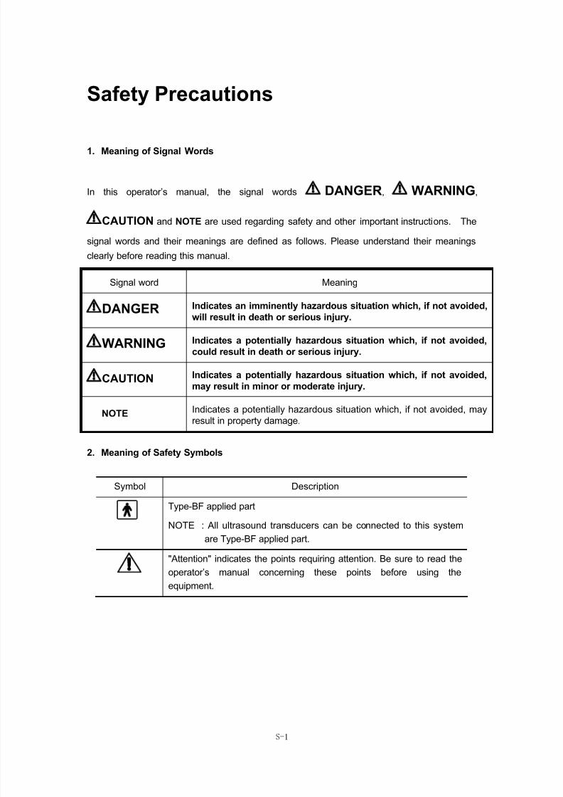
1. Meaning of Signal Words
In this operator’s manual, the signal words DANGER, WARNING,
CAUTION and NOTE are used regarding safety and other important instructions. The
signal words and their meanings are defined as follows. Please understand their meanings
clearly before reading this manual.
Signal word Meaning
DANGER Indicates an imminently hazardous situation which, if not avoided,
will result in death or serious injury.
WARNING Indicates a potentially hazardous situation which, if not avoided,
could result in death or serious injury.
CAUTION Indicates a potentially hazardous situation which, if not avoided,
may result in minor or moderate injury.
NOTE Indicates a potentially hazardous situation which, if not avoided, may
result in property damage.
2. Meaning of Safety Symbols
Symbol Description
Type-BF applied part
NOTE : All ultrasound transducers can be connected to this system
are Type-BF applied part.
"Attention" indicates the points requiring attention. Be sure to read theoperator’s manual concerning these points before using the
equipment.
8/11/2019 Mindray DP6600
http://slidepdf.com/reader/full/mindray-dp6600 6/113
S-2
3. Safety Precautions
Please observe the following precautions to ensure patient and operator safety when using
this system.
CAUTION: 1. Display the most suitable image and select the most suitable
measurement mode for the intended measurement. The results
must be determined by a specialist.
2. The basic measurement results are not displayed in the exam
report.
3. Be sure to perform measurement within images. If the area is
outside the image, incorrect diagnosis may result.
4. The detailed precautions for each measurement are described in
the corresponding section. Read and understand these
precautions before performing the measurement.
5. Data in temporary storage areas, such as the CINE memory, is
deleted when the power supply is turned OFF or when the Patient
switch is pressed. Such data may also occasionally be deleted
due to accidents. To minimize the possibility of reexamination
being required as a result of unintended data deletion, back up the
required images on external storage media.
6. Refer to the Operator’s Manual (Basic Volume) for precautions
regarding the use of this system.
8/11/2019 Mindray DP6600
http://slidepdf.com/reader/full/mindray-dp6600 7/113
C-1
Contents
Contents .........................................................................................................1
1 Preset.....................................................................................................1-1
1.1 Access/Exit Preset Mode................................................................................ 1-1
1.2 Display/Modify Preset Information .................................................................. 1-2
1.3 General preset ................................................................................................ 1-3
1.4 Preset Parameters of Exam Mode.................................................................. 1-5
1.5 Preset Formula ............................................................................................... 1-9
1.6 Preset Post Process Curve and Parameter .................................................. 1-12
1.6.1 Gray Transformation Curve............................................................................ 1-12
1.6.2 Gray rejection curve....................................................................................... 1-13
1.6.3 γ correction ....................................................................................................1-13
1.7 Preset comment............................................................................................ 1-14
1.7.1 Adding Comment ...........................................................................................1-15
1.7.2 Deleting Comment ......................................................................................... 1-15
1.8 Save/Load Preset Data................................................................................. 1-16
1.8.1 Save Preset Data........................................................................................... 1-16
1.8.2 Load DTA file ................................................................................................. 1-17
1.8.3 Factory Data .................................................................................................. 1-18
1.9 Maintenance ................................................................................................. 1-18
1.10 Preset DICOM .............................................................................................. 1-18
2 Basic Operation of Measurements & Calculations ............................2-1
2.1 Select the Exam Mode.................................................................................... 2-1
2.2 Accessing Measurement Status...................................................................... 2-1
2.3 Measurement Menu........................................................................................ 2-1
2.4 Measured Result and Help Information........................................................... 2-3
2.5 Keys Used during Measurement..................................................................... 2-3
2.6 Classification of Measurements and Calculations........................................... 2-5
2.7 Attention.......................................................................................................... 2-6
3 B mode General Measurements & Calculations.................................3-1
3.1 Distance.......................................................................................................... 3-2
3.2 Circumference and Area ................................................................................. 3-2 3.3 Volume............................................................................................................ 3-4
8/11/2019 Mindray DP6600
http://slidepdf.com/reader/full/mindray-dp6600 8/113
C-2
3.4 Ratio ............................................................................................................... 3-5
3.5 Stenosis Ratio................................................................................................. 3-5
3.6 Angle............................................................................................................... 3-7
3.7 Histogram ....................................................................................................... 3-7
3.8 Profile.............................................................................................................. 3-8
3.9 Other Measurements ...................................................................................... 3-9
3.10 Print General Report ....................................................................................... 3-9
4 M Mode General Measurements & Calculations.................................4-1
4.1 Distance.......................................................................................................... 4-1
4.2 Time................................................................................................................ 4-2
4.3 Slope............................................................................................................... 4-2
4.4 Heart Rate ...................................................................................................... 4-3
5 Obstetric Measurements & Calculations ............................................5-1
5.1 Abbreviations used ......................................................................................... 5-2
5.2 Measurement items ........................................................................................ 5-2
5.3 Fetal Growth Measurements........................................................................... 5-3
5.3.1 GS ................................................................................................................... 5-3
5.3.2 CRL ................................................................................................................. 5-4
5.3.3 BPD ................................................................................................................. 5-4
5.3.4 HC ................................................................................................................... 5-4
5.3.5 AC.................................................................................................................... 5-5
5.3.6 FL ....................................................................................................................5-5
5.3.7 AFI ................................................................................................................... 5-6
5.3.8 TAD.................................................................................................................. 5-6
5.3.9 APAD ............................................................................................................... 5-6
5.3.10 CER ............................................................................................................... 5-7
5.3.11 FTA ................................................................................................................ 5-7 5.3.12 HUM............................................................................................................... 5-7
5.3.13 OFD ............................................................................................................... 5-8
5.3.14 THD ............................................................................................................... 5-8
5.4 EDD................................................................................................................ 5-9
5.4.1 Calculating the EDD according to LMP............................................................ 5-9
5.4.2 Calculating the EDD according to BBT ............................................................ 5-9
5.5 EFW.............................................................................................................. 5-10
5.5.1 Formulae........................................................................................................ 5-10
8/11/2019 Mindray DP6600
http://slidepdf.com/reader/full/mindray-dp6600 9/113
C-3
5.5.2 Measurement items ....................................................................................... 5-11
5.5.3 Sample........................................................................................................... 5-11
5.6 Results.......................................................................................................... 5-11
5.6.1 Growth Curves Comparison........................................................................... 5-11
5.6.2 Fetal Biophysical Profile................................................................................. 5-13
5.6.3 FBP Report .................................................................................................... 5-16
5.6.4 Obstetric Exam Report................................................................................... 5-17
5.6.5 Printing Obstetric Report................................................................................ 5-18
5.7 Others ........................................................................................................... 5-19
5.8 References ................................................................................................... 5-20
6 Cardiac Measurements & Calculations...............................................6-1
6.1 M Mode Measurements .................................................................................. 6-1
6.1.1 LV..................................................................................................................... 6-6
6.1.2 SV, EF, FS........................................................................................................ 6-6
6.1.3 CO ................................................................................................................... 6-7
6.1.4 MVCF............................................................................................................... 6-8
6.1.5 CI, SI................................................................................................................ 6-9
6.1.6 Measuring all parameters of LV simultaneous ................................................. 6-9
6.1.7 LVMW and LVMWI......................................................................................... 6-10
6.1.8 Mitral measurement ....................................................................................... 6-11
6.1.9 Aorta measurement........................................................................................ 6-12
6.2 B Mode Measurements................................................................................. 6-13
6.2.1 LV measurement using Single Plane Ellipse method..................................... 6-18
6.2.2 Others measurement method for LV.............................................................. 6-18
6.2.3 CO ................................................................................................................. 6-19
6.2.4 Entering LVET................................................................................................ 6-19
6.2.5 CI, SI.............................................................................................................. 6-19 6.2.6 RV.................................................................................................................. 6-20
6.2.7 PA.................................................................................................................. 6-20
6.2.8 Other Parameters .......................................................................................... 6-20
6.3 Cardiac Exam Report ...................................................................................6-20
7 Gynecology Measurements & Calculations........................................7-1
7.1 UT (Uterine body) ...........................................................................................7-3
7.2 Endo (Endometrium)....................................................................................... 7-3
7.3 OV-V (Ovary Volume) ..................................................................................... 7-3
8/11/2019 Mindray DP6600
http://slidepdf.com/reader/full/mindray-dp6600 10/113
C-4
7.3.1 L.OV-V............................................................................................................. 7-3
7.3.2 R.OV-V............................................................................................................. 7-4
7.4 FO-D (Dominant Follicle) ................................................................................ 7-4
7.4.1 L.FO................................................................................................................. 7-4
7.4.2 R.FO ................................................................................................................ 7-5
7.5 CX-L (Uterine Cervix Length).......................................................................... 7-5
7.6 UT-L/CX-L (Uterine body / cervix) ................................................................... 7-5
7.7 Others ............................................................................................................. 7-5
7.8 Gynecology Exam Report ............................................................................... 7-6
8 Small parts Measurements & Calculations .........................................8-1
8.1 THY (Thyroid) ................................................................................................. 8-2
8.1.1 L.THY-V ........................................................................................................... 8-2
8.1.2 R.THY-V........................................................................................................... 8-3
8.2 THY RPT ........................................................................................................ 8-3
8.3 Others ............................................................................................................. 8-4
9 Urology Measurements & Calculations...............................................9-1
9.1 RUV ................................................................................................................ 9-2
9.2 Prostate Volume ............................................................................................. 9-3
9.3 PSAD.............................................................................................................. 9-3
9.4 Urology Exam Report ..................................................................................... 9-4
9.5 Others ............................................................................................................. 9-4
10 Orthopedics Measurements & Calculations .....................................10-1
10.1 HIP................................................................................................................ 10-2
10.2 HIP RPT........................................................................................................ 10-3
10.3 Others ........................................................................................................... 10-3
8/11/2019 Mindray DP6600
http://slidepdf.com/reader/full/mindray-dp6600 11/113
1-1
1Preset
Preset function is used to set the system operating environment, status and the configuration
parameters for each exam mode. The preset values are saved in the memory inside the
system, which will not be lost if power-off occurs so as to ensure that the system operates in
the user-desired status automatically after each start-up. This chapter gives detailed
description about how to make system configuration through using the preset menu in Preset
mode.
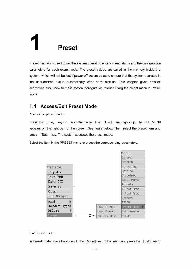
1.1 Access/Exit Preset Mode
Access the preset mode:
Press the 『File』 key on the control panel. The 『File』 lamp lights up. The FILE MENU
appears on the right part of the screen. See figure below. Then select the preset item and
press 『Set』 key. The system accesses the preset mode.
Select the item in the PRESET menu to preset the corresponding parameters.
Exit Preset mode:
In Preset mode, move the cursor to the [Return] item of the menu and press the 『Set』key to
8/11/2019 Mindray DP6600
http://slidepdf.com/reader/full/mindray-dp6600 12/113
Preset
1-2
close the PRESET menu. The system exits the preset mode and begins running according
the modified parameters.
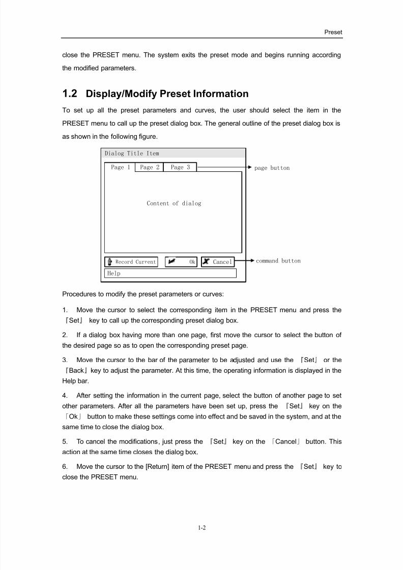
1.2 Display/Modify Preset Information
To set up all the preset parameters and curves, the user should select the item in the
PRESET menu to call up the preset dialog box. The general outline of the preset dialog box is
as shown in the following figure.
Dialog Title Item
Page 1 Page 2 Page 3
Help
Content of dialog
page button
command buttonCancelRecord Current Ok
Procedures to modify the preset parameters or curves:
1. Move the cursor to select the corresponding item in the PRESET menu and press the
『Set』 key to call up the corresponding preset dialog box.
2. If a dialog box having more than one page, first move the cursor to select the button of
the desired page so as to open the corresponding preset page.
3. Move the cursor to the bar of the parameter to be adjusted and use the 『Set』 or the
『Back』key to adjust the parameter. At this time, the operating information is displayed in the
Help bar.
4. After setting the information in the current page, select the button of another page to set
other parameters. After all the parameters have been set up, press the 『Set』 key on the
「Ok」 button to make these settings come into effect and be saved in the system, and at the
same time to close the dialog box.
5. To cancel the modifications, just press the 『Set』 key on the 「Cancel」 button. This
action at the same time closes the dialog box.
6. Move the cursor to the [Return] item of the PRESET menu and press the 『Set』 key to
close the PRESET menu.
8/11/2019 Mindray DP6600
http://slidepdf.com/reader/full/mindray-dp6600 13/113
Preset
1-3
There are also some special buttons in the preset dialog box, whose functions are:
「Record Current」
Besides setting the parameters in the current page one by one, the user can also use the
“record the current value” method to preset parameters. Press the『Set』key on the「Record
Current」 to set each parameter (curve) as the value (parameter or curve) used by the system
before accessing the preset mode. That is to say to set up the current operating parameters
of the system as the preset parameters.
NOTE:「Record Current」 buttons are only valid in the current page.
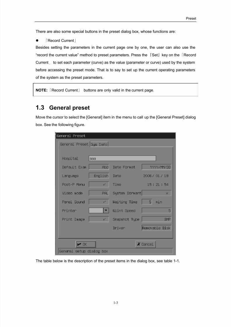
1.3 General preset
Move the cursor to select the [General] item in the menu to call up the [General Preset] dialog
box. See the following figure.
The table below is the description of the preset items in the dialog box, see table 1-1.
8/11/2019 Mindray DP6600
http://slidepdf.com/reader/full/mindray-dp6600 14/113
Preset
1-4
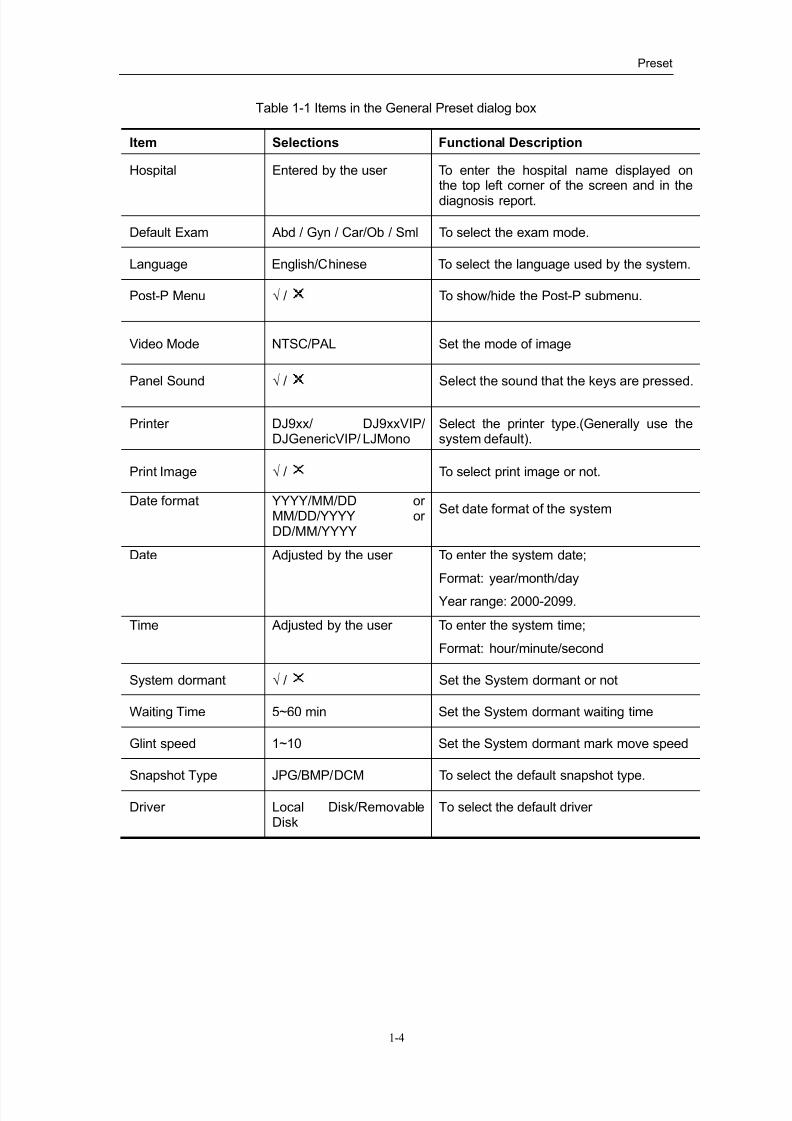
Table 1-1 Items in the General Preset dialog box
Item Selections Functional Description
Hospital Entered by the user To enter the hospital name displayed onthe top left corner of the screen and in the
diagnosis report.
Default Exam Abd / Gyn / Car/Ob / Sml To select the exam mode.
Language English/Chinese To select the language used by the system.
Post-P Menu √ / To show/hide the Post-P submenu.
Video Mode NTSC/PAL Set the mode of image
Panel Sound √ / Select the sound that the keys are pressed.
Printer DJ9xx/ DJ9xxVIP/DJGenericVIP/ LJMono
Select the printer type.(Generally use thesystem default).
Print Image √ / To select print image or not.
Date format YYYY/MM/DD orMM/DD/YYYY orDD/MM/YYYY
Set date format of the system
Date Adjusted by the user To enter the system date;
Format: year/month/day
Year range: 2000-2099.
Time Adjusted by the user To enter the system time;
Format: hour/minute/second
System dormant √ / Set the System dormant or not
Waiting Time 5~60 min Set the System dormant waiting time
Glint speed 1~10 Set the System dormant mark move speed
Snapshot Type JPG/BMP/DCM To select the default snapshot type.
Driver Local Disk/RemovableDisk
To select the default driver
8/11/2019 Mindray DP6600
http://slidepdf.com/reader/full/mindray-dp6600 15/113
Preset
1-5
1.4 Preset Parameters of Exam Mode
The system has five exam modes, which are abdomen (general), gynecology, cardiac,
obstetric and small parts. Each exam mode has preset the most suitable operating
environment. The preset contents of different exam modes are similar. Now use the obstetric
exam as an example to illustrate how to preset the operating environment.
The preset dialog box of the obstetric exam has three pages, which are “Parameter”,”B IP”
and “M IP”.
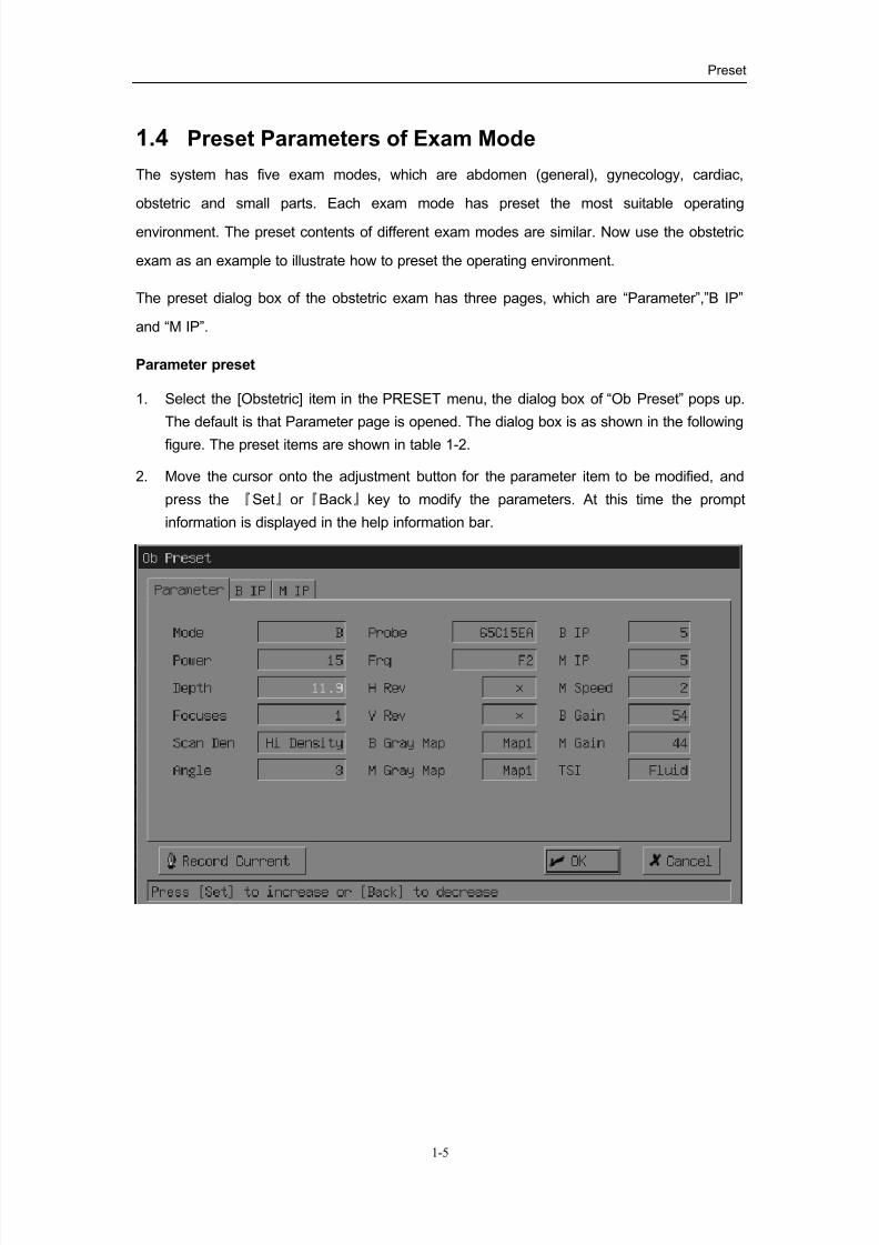
Parameter preset
1. Select the [Obstetric] item in the PRESET menu, the dialog box of “Ob Preset” pops up.
The default is that Parameter page is opened. The dialog box is as shown in the following
figure. The preset items are shown in table 1-2.
2. Move the cursor onto the adjustment button for the parameter item to be modified, and
press the 『Set』or 『Back』key to modify the parameters. At this time the prompt
information is displayed in the help information bar.
8/11/2019 Mindray DP6600
http://slidepdf.com/reader/full/mindray-dp6600 16/113
Preset
1-6
Table 1-2 the preset items in the parameter page
Item Selections Description
Mode B
MB RT + B
B + B RT
M + B RT
To select the image mode.
Power 0~15 To set the acoustic power in 16 steps.
Depth 2.16—24.8cm To set the scanning depth which has 20steps for low-frequency probe.
Scanning depth for high-frequency
probe has 10 steps.
Focuses 1 / 2 / 3 / 4 To set the number of focusesScan Den Hi Density / Hi Frm Rate To select the scan density
Angle 0 / 1 / 2 / 3 To set the scan angle of the probe
Probe All probes that the system supports. To select the type of probe
Frq F1, F2, F3 To set the probe frequency
H Rev √ / To set the attribute of the L/R flip
V Rev √ / To set the attribute of the U/D flip
B Gray Map Map1/Map2/Map3/
Map4/Map5
To set the post processing effect of the
B image.
M Gray
Map
Map1/Map2/Map3/
Map4/Map5
To set the post processing effect of the
M image.B IP 1~8 To set the combination of parameters
for B image processing in 8 steps.
M IP 1~8 To set the combination of parameters
for M image processing in 8 steps.
M Speed 1 / 2 / 3 / 4 To set the M mode scanning speed.
B Gain 0~98 To set the B mode image gain in 49
steps.
M Gain 0~98 To set the M mode image gain in 49
steps.
TSI General/Muscle/Fatty/Fluid To set the characteristic of the tissue
8/11/2019 Mindray DP6600
http://slidepdf.com/reader/full/mindray-dp6600 17/113
Preset
1-7
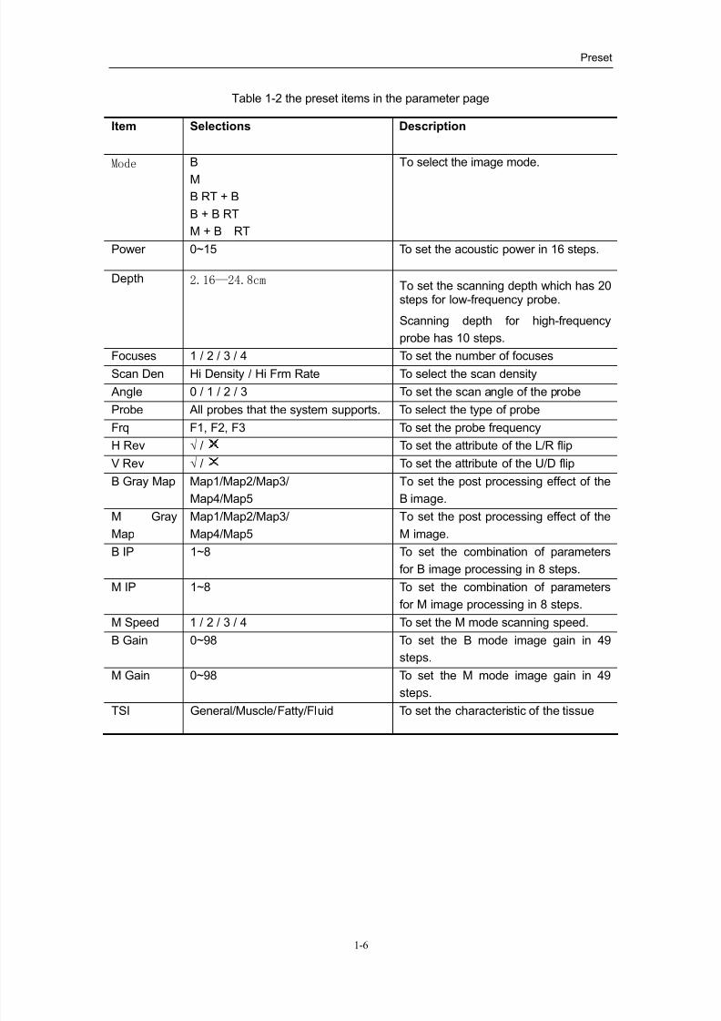
B IP preset
1. Select the [B IP] preset page. See the dialog box below. The preset items are shown in
table 1-3.
2. Move the cursor onto the adjustment button for the parameter item to be modified, and
press the『Set』or 『Back』key to modify the parameters. At this time the prompt information
is displayed in the help information bar.
Table 1-3 the preset items in the B IP preset page
Item Optional Item Functional Description
Dyn Rng 30 ~ 90 To set dynamic range in 16 steps with theincrement of 4.
Edge 0 ~ 3 To set edge enhancement in 4 steps.
Smooth 0 ~ 3 To set smooth processing in 4 steps.
Frame Avg 0 ~ 7 To set frame average in 8 steps.
Soften 0 ~ 3 To set image soften in 4 steps.
B AGC 0 ~ 3 To set B AGC in 4 steps.
Noise Rst 0 ~ 3 To set Noise Rst in 4 steps.
8/11/2019 Mindray DP6600
http://slidepdf.com/reader/full/mindray-dp6600 18/113
Preset
1-8
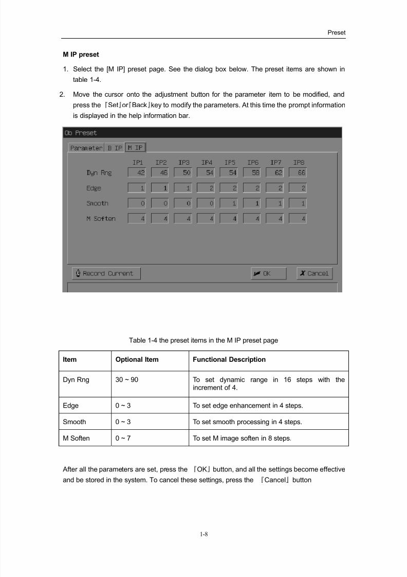
M IP preset
1. Select the [M IP] preset page. See the dialog box below. The preset items are shown in
table 1-4.
2. Move the cursor onto the adjustment button for the parameter item to be modified, and
press the『Set』or 『Back』key to modify the parameters. At this time the prompt information
is displayed in the help information bar.
Table 1-4 the preset items in the M IP preset page
Item Optional Item Functional Description
Dyn Rng 30 ~ 90 To set dynamic range in 16 steps with theincrement of 4.
Edge 0 ~ 3 To set edge enhancement in 4 steps.
Smooth 0 ~ 3 To set smooth processing in 4 steps.
M Soften 0 ~ 7 To set M image soften in 8 steps.
After all the parameters are set, press the 『OK』button, and all the settings become effective
and be stored in the system. To cancel these settings, press the 『Cancel』button
8/11/2019 Mindray DP6600
http://slidepdf.com/reader/full/mindray-dp6600 19/113
Preset
1-9
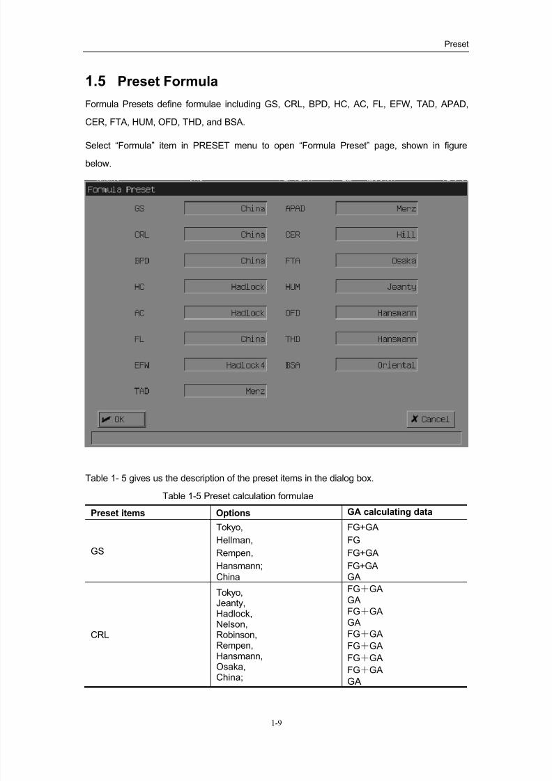
1.5 Preset Formula
Formula Presets define formulae including GS, CRL, BPD, HC, AC, FL, EFW, TAD, APAD,
CER, FTA, HUM, OFD, THD, and BSA.
Select “Formula” item in PRESET menu to open “Formula Preset” page, shown in figure
below.
Table 1- 5 gives us the description of the preset items in the dialog box.
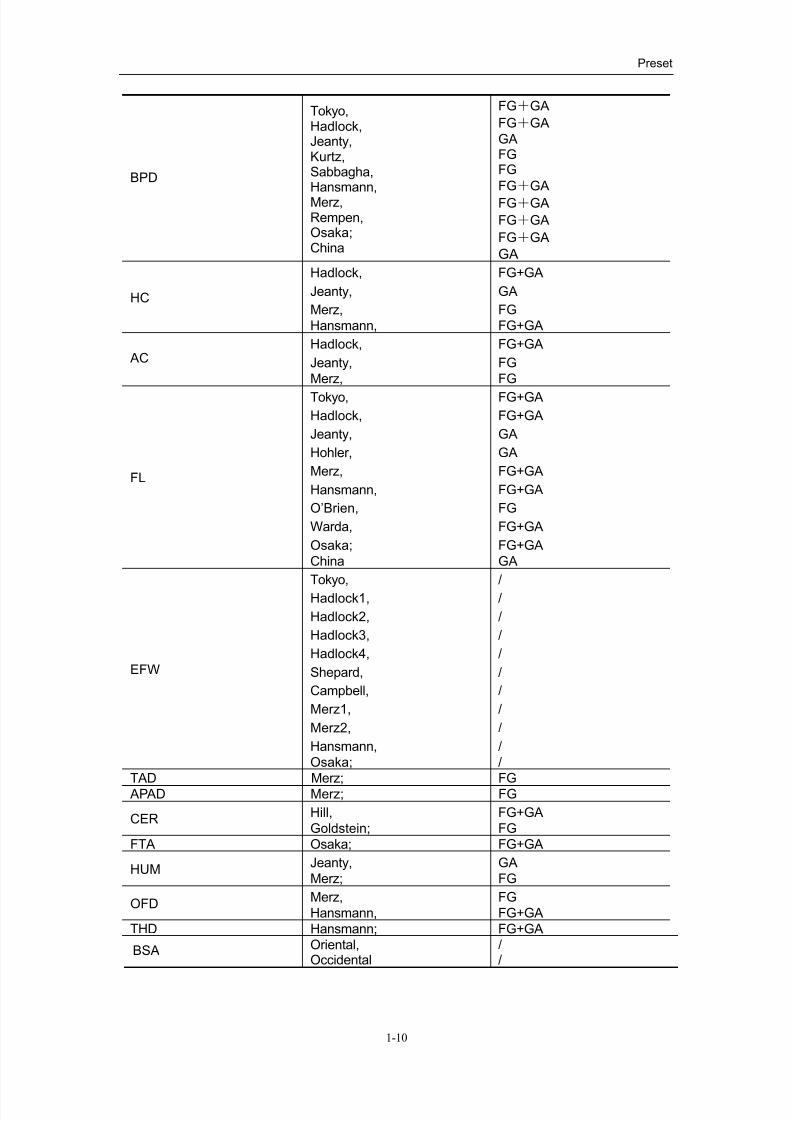
Table 1-5 Preset calculation formulae
Preset items Options GA calculating data
GS
Tokyo,
Hellman,
Rempen,
Hansmann;
China
FG+GA
FG
FG+GA
FG+GA
GA
CRL
Tokyo,Jeanty,Hadlock,Nelson,Robinson,Rempen,Hansmann,Osaka,China;
FG+GA
GA
FG+GA
GA
FG+GA
FG+GA
FG+GA
FG+GA
GA
8/11/2019 Mindray DP6600
http://slidepdf.com/reader/full/mindray-dp6600 20/113
Preset
1-10
BPD
Tokyo,Hadlock,Jeanty,Kurtz,Sabbagha,Hansmann,Merz,Rempen,Osaka;China
FG+GA
FG+GA
GAFGFG
FG+GA
FG+GA
FG+GA
FG+GA
GA
HC
Hadlock,
Jeanty,
Merz,
Hansmann,
FG+GA
GA
FG
FG+GA
ACHadlock,
Jeanty,
Merz,
FG+GA
FG
FG
FL
Tokyo,
Hadlock,
Jeanty,
Hohler,
Merz,
Hansmann,
O’Brien,
Warda,
Osaka;
China
FG+GA
FG+GA
GA
GA
FG+GA
FG+GA
FG
FG+GA
FG+GA
GA
EFW
Tokyo,
Hadlock1,
Hadlock2,
Hadlock3,
Hadlock4,
Shepard,
Campbell,
Merz1,
Merz2,
Hansmann,
Osaka;
/
/
/
/
/
/
/
/
/
/
/
TAD Merz; FG
APAD Merz; FG
CERHill,
Goldstein;
FG+GA
FG
FTA Osaka; FG+GA
HUMJeanty,
Merz;
GA
FG
OFDMerz,
Hansmann,
FG
FG+GA
THD Hansmann; FG+GA
BSA Oriental,Occidental
//

8/11/2019 Mindray DP6600
http://slidepdf.com/reader/full/mindray-dp6600 21/113
Preset
1-11
FG and GA are used in these formulae. In formula preset, three situations are presented for
each item. Some formulae are included in both FG and GA tables but others are exclusive for
GA or FG table. Please select reasonable formula according to below information:
1. In the process of obstetric measurement, if the user does not enter LMP or BBT, GA table
will be required for calculating GA. If the preset formula does not have corresponding GA
table, the system will not display GA. If the user has entered LMP or BBT, FG table will then
be required for calculating GA. If the preset formula does not have corresponding FG table,
the system will not display GA. After the user has entered LMP or BBT, the system will
calculate GA based on FG table for all obstetric measured items. And at the same time the
result window and report will be refreshed.
2. Data of growth curve are all sourced from FG table. The user could select the formula in
the pull-down list. The system will accordingly display the growth curve corresponding to the
formula. The initial curve being displayed is decided by the preset formula. If the formula does
not have corresponding FG table, fetal growth curve will not be displayed.
8/11/2019 Mindray DP6600
http://slidepdf.com/reader/full/mindray-dp6600 22/113
Preset
1-12
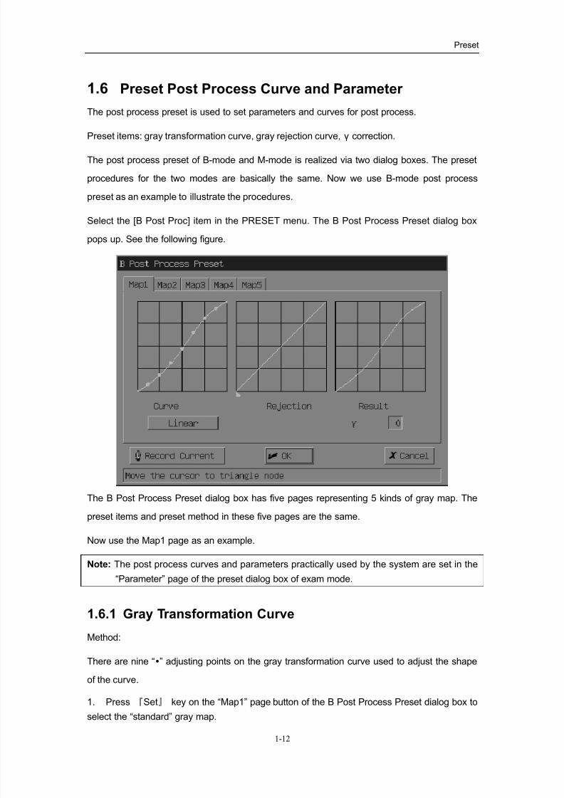
1.6 Preset Post Process Curve and Parameter
The post process preset is used to set parameters and curves for post process.
Preset items: gray transformation curve, gray rejection curve, γ correction.
The post process preset of B-mode and M-mode is realized via two dialog boxes. The preset
procedures for the two modes are basically the same. Now we use B-mode post process
preset as an example to illustrate the procedures.
Select the [B Post Proc] item in the PRESET menu. The B Post Process Preset dialog box
pops up. See the following figure.
The B Post Process Preset dialog box has five pages representing 5 kinds of gray map. The
preset items and preset method in these five pages are the same.
Now use the Map1 page as an example.
Note: The post process curves and parameters practically used by the system are set in the
“Parameter” page of the preset dialog box of exam mode.
1.6.1 Gray Transformation Curve
Method:
There are nine “” adjusting points on the gray transformation curve used to adjust the shape
of the curve.
1. Press 『Set』 key on the “Map1” page button of the B Post Process Preset dialog box to
select the “standard” gray map.
8/11/2019 Mindray DP6600
http://slidepdf.com/reader/full/mindray-dp6600 23/113
Preset
1-13
2. Move the cursor to an adjusting point on the curve, the cursor changes into a “ ”.
Press the 『Set』 key and roll the trackball to move the “” so as to adjust the curve. After
adjusting the curve, press the『Set』key again to finish the adjustment. Or press the『Back』
key to cancel the operation, the “” point will return to the original position. The system
updates the “Result” curve. Use the same method to adjust other points.
3. Another way to set the gray transformation curve is adjusted by using the 「Record
Current」 button. Actually, this method is a more practical one. Press the 『Set』 key on the
「Record Current」 to set the curve as the one currently used by the system and
simultaneously to load the gray rejection curve and γ correction currently used by the system
into the current page of the dialog box.
4. Press the 『Set』 key on the [Linear] button, the gray transformation curve will return to
the factory default shape.
5. Press the『Set』 key on the 「Ok」 button to save the modification or on the 「Cancel」
button to give up the modification and close the dialog box at the same time.
Note: The [Linear] button is only valid to the gray transformation curve. This button is invalid
to gray rejection curve and γ correction.
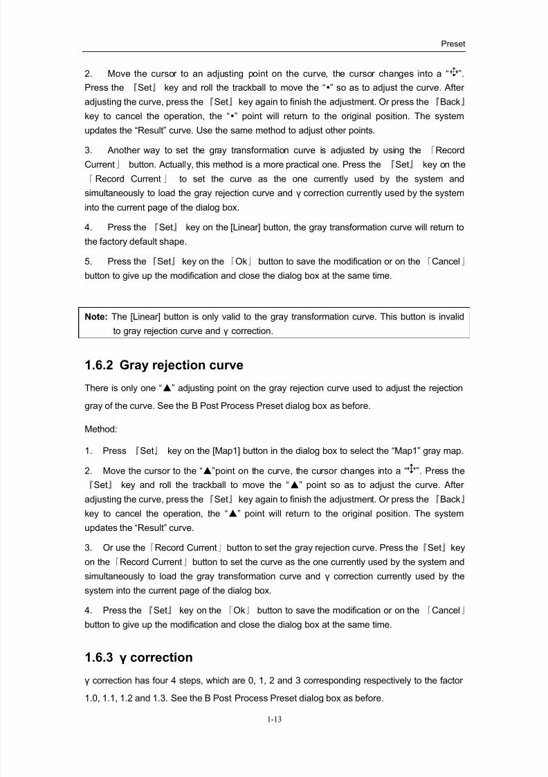
1.6.2 Gray rejection curve
There is only one “▲” adjusting point on the gray rejection curve used to adjust the rejection
gray of the curve. See the B Post Process Preset dialog box as before.
Method:
1. Press 『Set』 key on the [Map1] button in the dialog box to select the “Map1” gray map.
2. Move the cursor to the “▲”point on the curve, the cursor changes into a “ ”. Press the
『Set』 key and roll the trackball to move the “▲” point so as to adjust the curve. After
adjusting the curve, press the『Set』key again to finish the adjustment. Or press the『Back』
key to cancel the operation, the “▲” point will return to the original position. The system
updates the “Result” curve.
3. Or use the「Record Current」button to set the gray rejection curve. Press the『Set』key
on the「Record Current」button to set the curve as the one currently used by the system and
simultaneously to load the gray transformation curve and γ correction currently used by the
system into the current page of the dialog box.
4. Press the 『Set』 key on the 「Ok」 button to save the modification or on the 「Cancel」
button to give up the modification and close the dialog box at the same time.
1.6.3 γ correction
γ correction has four 4 steps, which are 0, 1, 2 and 3 corresponding respectively to the factor
1.0, 1.1, 1.2 and 1.3. See the B Post Process Preset dialog box as before.
8/11/2019 Mindray DP6600
http://slidepdf.com/reader/full/mindray-dp6600 24/113
Preset
1-14
Method:
1. Press the [Map1] button in the dialog box to select the “Map1” gray map.
2. Move the cursor to the [γ] button and press the 『Set』 or the 『Back』 key to select an
appropriate γ value. The system updates the “Result” curve.
3. Or use the「Record Current」button to set γ value. Press the『Set』key on the「Record
Current」 to set the γ value as the one currently used by the system and simultaneously to
load the gray transformation curve and gray rejection curve currently used by the system into
the current page of the dialog box.
4. Press the 『Set』 key on the 「Ok」 button to save the modification or on the 「Cancel」
button to give up the modification and close the dialog box at the same time.
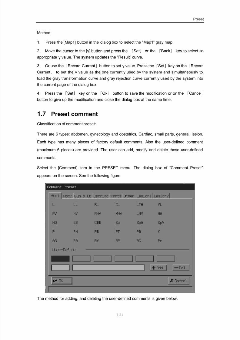
1.7 Preset comment
Classification of comment preset:
There are 6 types: abdomen, gynecology and obstetrics, Cardiac, small parts, general, lesion.
Each type has many pieces of factory default comments. Also the user-defined comment
(maximum 6 pieces) are provided. The user can add, modify and delete these user-defined
comments.
Select the [Comment] item in the PRESET menu. The dialog box of “Comment Preset”
appears on the screen. See the following figure.
The method for adding, and deleting the user-defined comments is given below.
8/11/2019 Mindray DP6600
http://slidepdf.com/reader/full/mindray-dp6600 25/113
Preset
1-15
1.7.1 Adding Comment
Method:
Now use adding user-defined comments into the「Parts」page as an example to illustrate the
process.
1. Press the 「Parts」 page button to open the “Small Parts” comment page.
2. Move the cursor to a piece of “User-Define” button, the cursor then changes into a .
Press the 『Set』 key to highlight this piece of comment.
3. Move the cursor into the left edit bar of “User-Define” comment and press the『Set』key.
Then the “|” cursor displays in the edit bar. Use the keyboard to enter the content of the
user-defined comment.
4. Move the cursor into the right edit bar of the “User-Define” comment and press the『Set』
key. Then the “|” cursor displays in this edit bar. Use the keyboard to enter the help orexplanation information for this piece of user-defined comment. (If no help information is to be
added, this step can be omitted.)
5. Press the『Set』key on the「 Add」button. The entered comment is displayed in the item
of the user-defined comment selected the step 2.
6. Press the 『Set』 key on the 「Ok」 button to save the modification or on the 「Cancel」
button to give up the modification and close the dialog box at the same time.
1.7.2 Deleting CommentMethod:
Use the deletion of the user-defined comment in the 「Parts」page as an example to illustrate
the process.
1. Press the 「Parts」 button to open the “Small Parts” comment page.
2. Move the cursor on the button of a piece of already existed “user-defined comment”, then
the cursor changes into a . Press the 『Set』 key to highlight this piece of comment.
3. Move the cursor to the 「Del」 button and press the 『Set』 key. The selected piece of
comment is then deleted.
4. Press the 『Set』 key on the 「Ok」 button to save the modification or on the 「Cancel」
button to give up the modification and close the dialog box at the same time.
8/11/2019 Mindray DP6600
http://slidepdf.com/reader/full/mindray-dp6600 26/113
Preset
1-16
1.8 Save/Load Preset Data
DTA file is used to store/load the preset data of the system.
1.8.1 Save Preset Data
The method is same as saving the image file, the expanded name of the file is DTA.
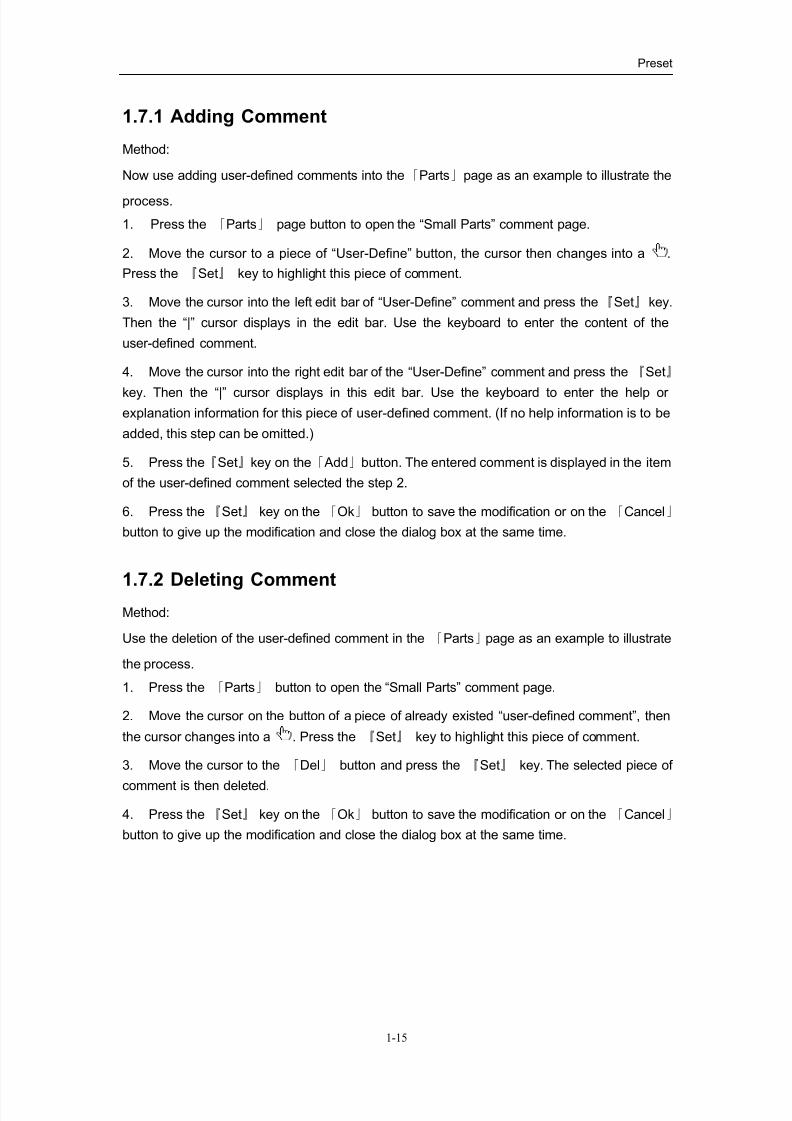
Method:
1. Move the cursor to the [Save Preset] item of the [Preset Data] submenu of PRESET
Menu and press the 『Set』 key. The dialog box of Save As appears on the screen.
2. Select the drive:
Select the drive in a pull-down list.
Move the cursor to the “▼” sign to the right of the drive. Press 『Set』 key, the list as
shown in the figure appears. The list shows to us the disk drives applicable to the
system.
Move the cursor to select the drive to be opened and then press 『Set』 key to close
the list. Then the selected drive becomes the current drive.
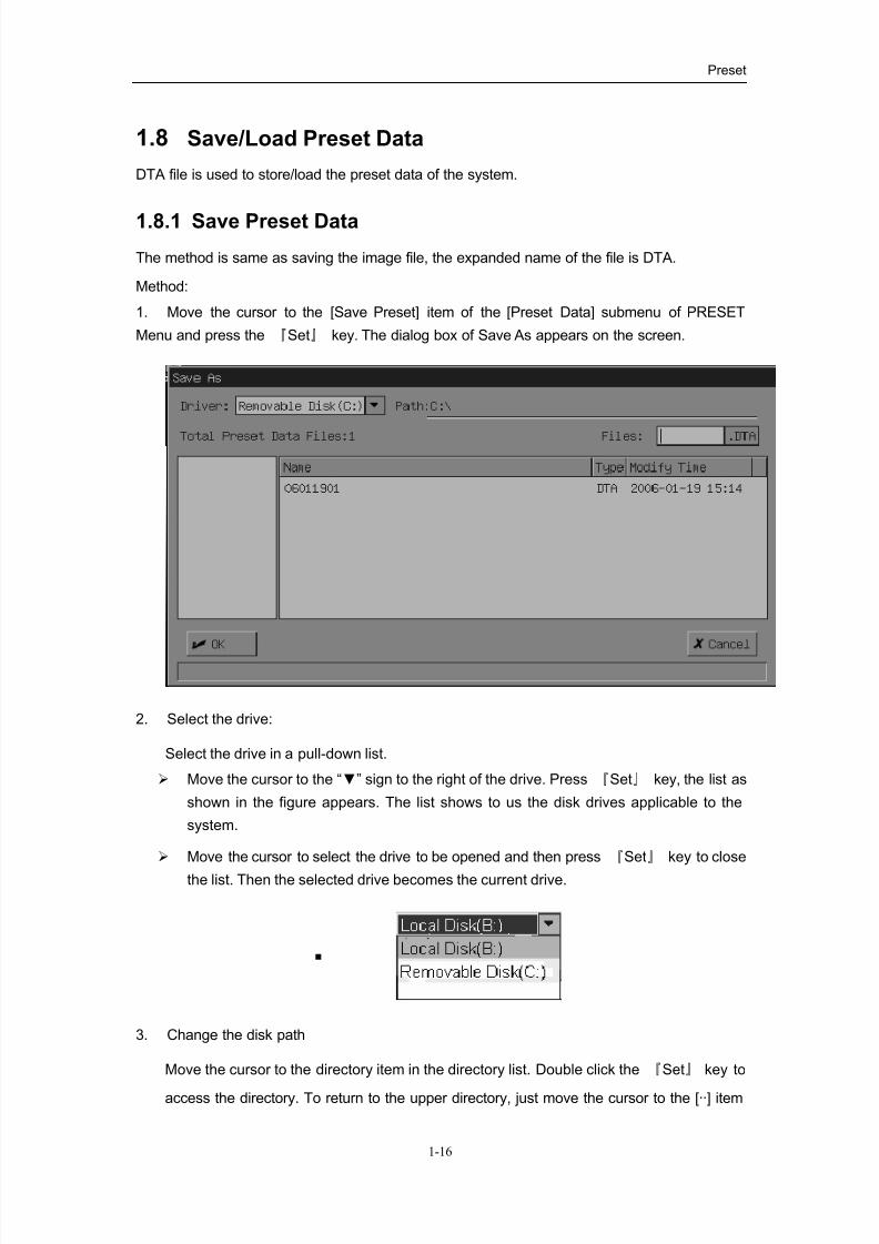
3. Change the disk path
Move the cursor to the directory item in the directory list. Double click the 『Set』 key to
access the directory. To return to the upper directory, just move the cursor to the [··] item
8/11/2019 Mindray DP6600
http://slidepdf.com/reader/full/mindray-dp6600 27/113
Preset
1-17
and double press the 『Set』 key for consecutive two times.
4. Enter the file name
Anchor the cursor into the FILE bar and press the 『Set』 key. Enter the file name. The
file type, i.e., the expanded name of the file “DTA”, cannot be modified.
To replace the existed file, just move the cursor to the corresponding file in the file list and
press the 『Set』 key.
5. Press the 『Set』 key on the 「Ok」 button to close the dialog box. The system will
automatically store the information displayed on the current screen into the specified file.
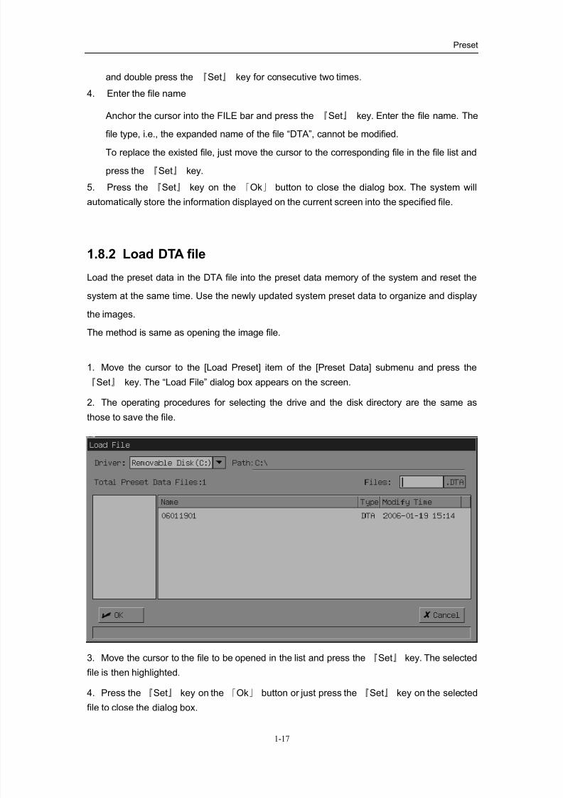
1.8.2 Load DTA file
Load the preset data in the DTA file into the preset data memory of the system and reset the
system at the same time. Use the newly updated system preset data to organize and display
the images.
The method is same as opening the image file.
1. Move the cursor to the [Load Preset] item of the [Preset Data] submenu and press the
『Set』 key. The “Load File” dialog box appears on the screen.
2. The operating procedures for selecting the drive and the disk directory are the same as
those to save the file.
3. Move the cursor to the file to be opened in the list and press the 『Set』 key. The selected
file is then highlighted.
4. Press the 『Set』 key on the 「Ok」 button or just press the 『Set』 key on the selected
file to close the dialog box.
8/11/2019 Mindray DP6600
http://slidepdf.com/reader/full/mindray-dp6600 28/113
Preset
1-18
5. After opening the DTA file, exit the File status. The system then resets and displays the
images based on the updated system preset data.
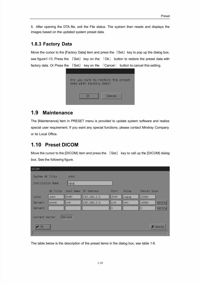
1.8.3 Factory Data
Move the cursor to the [Factory Data] item and press the『Set』 key to pop up the dialog box,
see figure1-13. Press the 『Set』 key on the 「Ok」 button to restore the preset data with
factory data. Or Press the 『Set』 key on the 「Cancel」 button to cancel this setting.
1.9 Maintenance
The [Maintenance] item in PRESET menu is provided to update system software and realize
special user requirement. If you want any special functions, please contact Mindray Company
or its Local Office.
1.10 Preset DICOM
Move the cursor to the [DICOM] item and press the 『Set』 key to call up the [DICOM] dialog
box. See the following figure.
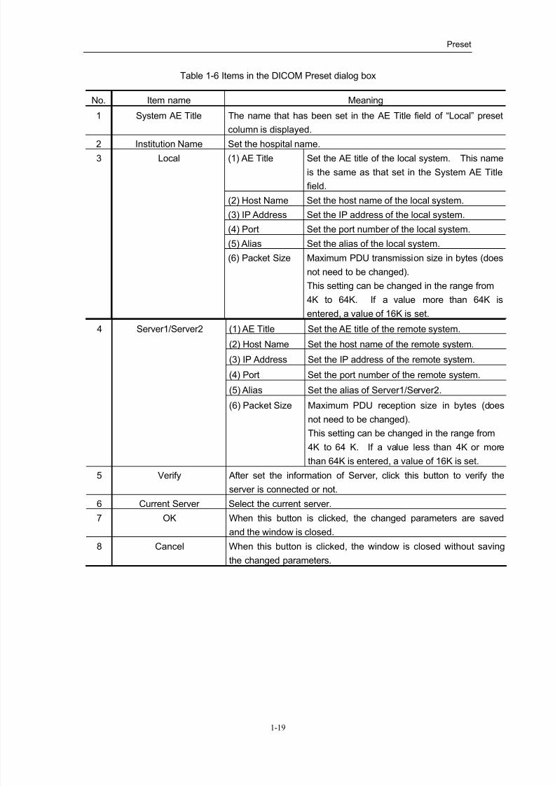
The table below is the description of the preset items in the dialog box, see table 1-6.
8/11/2019 Mindray DP6600
http://slidepdf.com/reader/full/mindray-dp6600 29/113
Preset
1-19
Table 1-6 Items in the DICOM Preset dialog box
No. Item name Meaning
1 System AE Title The name that has been set in the AE Title field of “Local” preset
column is displayed.
2 Institution Name Set the hospital name.
(1) AE Title Set the AE title of the local system. This name
is the same as that set in the System AE Title
field.
(2) Host Name Set the host name of the local system.
(3) IP Address Set the IP address of the local system.
(4) Port Set the port number of the local system.
(5) Alias Set the alias of the local system.
3 Local
(6) Packet Size Maximum PDU transmission size in bytes (does
not need to be changed).This setting can be changed in the range from
4K to 64K. If a value more than 64K is
entered, a value of 16K is set.
(1) AE Title Set the AE title of the remote system.
(2) Host Name Set the host name of the remote system.
(3) IP Address Set the IP address of the remote system.
(4) Port Set the port number of the remote system.
(5) Alias Set the alias of Server1/Server2.
4 Server1/Server2
(6) Packet Size Maximum PDU reception size in bytes (does
not need to be changed).
This setting can be changed in the range from
4K to 64 K. If a value less than 4K or more
than 64K is entered, a value of 16K is set.
5 Verify After set the information of Server, click this button to verify the
server is connected or not.
6 Current Server Select the current server.
7 OK When this button is clicked, the changed parameters are saved
and the window is closed.
8 Cancel When this button is clicked, the window is closed without savingthe changed parameters.
8/11/2019 Mindray DP6600
http://slidepdf.com/reader/full/mindray-dp6600 30/113
2-1
2Basic Operation of Measurements
& Calculations
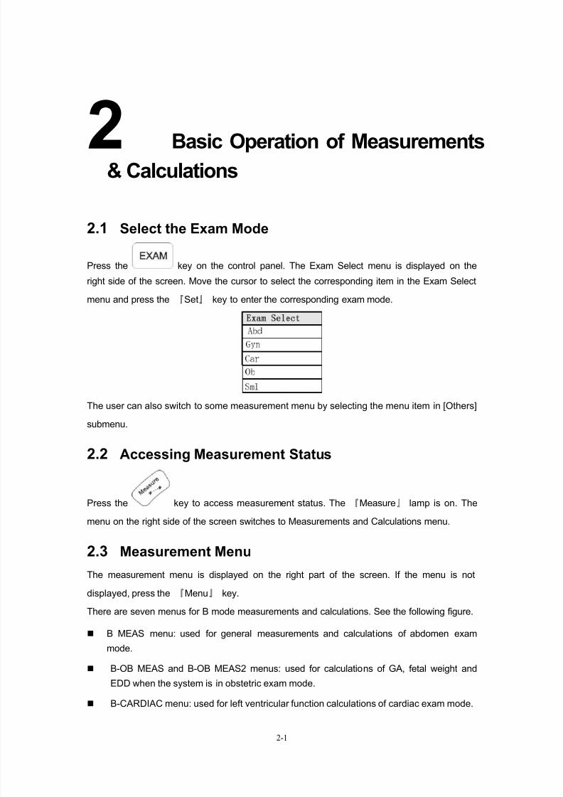
2.1 Select the Exam Mode
Press the key on the control panel. The Exam Select menu is displayed on the
right side of the screen. Move the cursor to select the corresponding item in the Exam Select
menu and press the 『Set』 key to enter the corresponding exam mode.
The user can also switch to some measurement menu by selecting the menu item in [Others]
submenu.
2.2 Accessing Measurement Status
Press the key to access measurement status. The 『Measure』 lamp is on. The
menu on the right side of the screen switches to Measurements and Calculations menu.
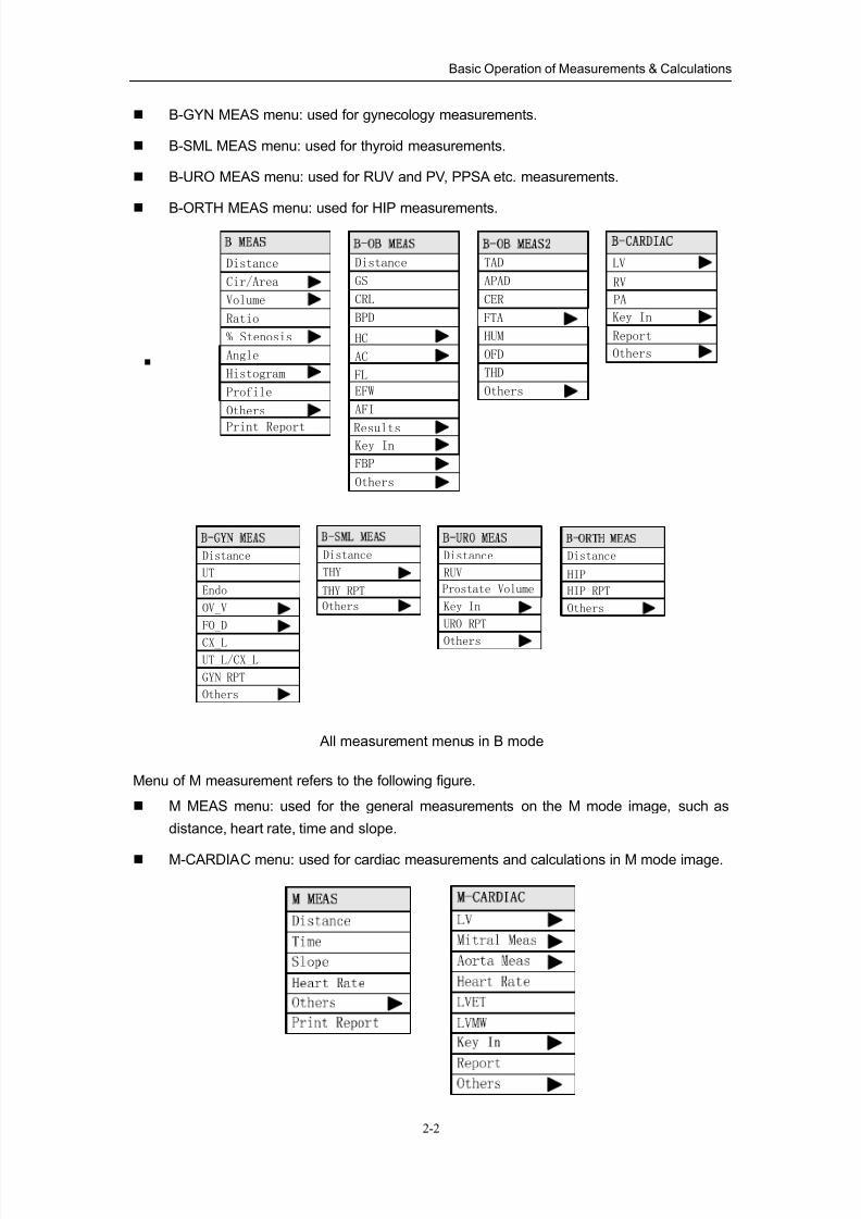
2.3 Measurement MenuThe measurement menu is displayed on the right part of the screen. If the menu is not
displayed, press the 『Menu』 key.
There are seven menus for B mode measurements and calculations. See the following figure.
B MEAS menu: used for general measurements and calculations of abdomen exam
mode.
B-OB MEAS and B-OB MEAS2 menus: used for calculations of GA, fetal weight and
EDD when the system is in obstetric exam mode.
B-CARDIAC menu: used for left ventricular function calculations of cardiac exam mode.
8/11/2019 Mindray DP6600
http://slidepdf.com/reader/full/mindray-dp6600 31/113
Basic Operation of Measurements & Calculations
2-2
B-GYN MEAS menu: used for gynecology measurements.
B-SML MEAS menu: used for thyroid measurements.
B-URO MEAS menu: used for RUV and PV, PPSA etc. measurements.
B-ORTH MEAS menu: used for HIP measurements.
Cir/Area
Distance
% Stenosis
Volume
Angle
Histogram
Ratio
Profile
Others
Print Report
GS
Distance
BPD
CRL
HC
AC
EFW
AFI
ResultsKey In
Others
FBP
TAD
CER
APAD
FTA
HUM
OFD
THD
Others
RV
LV
Key In
PA
FL
Others
Report
UT
Distance
Endo
OV_V
FO_D
CX_LUT_L/CX_L
GYN RPT
Others
Distance
THY
THY RPT
Others
RUV
Distance
Prostate Volume
Key In
URO RPT
Others
Distance
HIP
HIP RPT
Others
All measurement menus in B mode
Menu of M measurement refers to the following figure.
M MEAS menu: used for the general measurements on the M mode image, such as
distance, heart rate, time and slope.
M-CARDIAC menu: used for cardiac measurements and calculations in M mode image.
8/11/2019 Mindray DP6600
http://slidepdf.com/reader/full/mindray-dp6600 32/113
Basic Operation of Measurements & Calculations
2-3
Toggle among measurement menus:
The type of the displayed measurement menu depends on the current exam mode.
The user can also select the menu item in [Others] submenu to enter other exam mode.
The details of measurement menus are explained in following description of measurements.
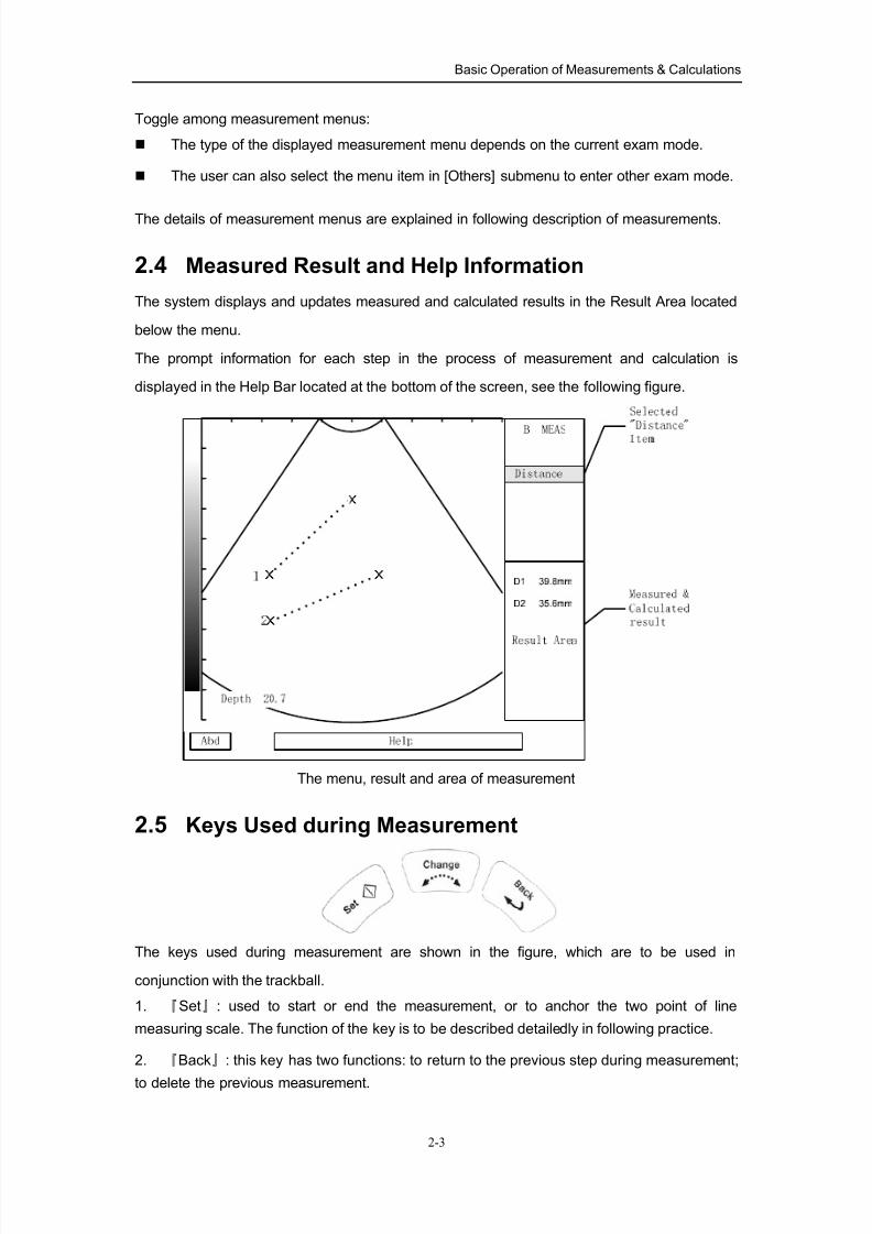
2.4 Measured Result and Help Information
The system displays and updates measured and calculated results in the Result Area located
below the menu.
The prompt information for each step in the process of measurement and calculation is
displayed in the Help Bar located at the bottom of the screen, see the following figure.
The menu, result and area of measurement
2.5 Keys Used during Measurement
The keys used during measurement are shown in the figure, which are to be used in
conjunction with the trackball.
1. 『Set』: used to start or end the measurement, or to anchor the two point of line
measuring scale. The function of the key is to be described detailedly in following practice.
2. 『Back』: this key has two functions: to return to the previous step during measurement;
to delete the previous measurement.
8/11/2019 Mindray DP6600
http://slidepdf.com/reader/full/mindray-dp6600 33/113
Basic Operation of Measurements & Calculations
2-4
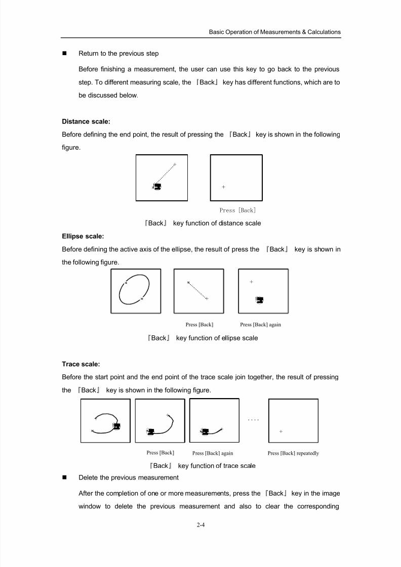
Return to the previous step
Before finishing a measurement, the user can use this key to go back to the previous
step. To different measuring scale, the 『Back』 key has different functions, which are to
be discussed below.
Distance scale:
Before defining the end point, the result of pressing the 『Back』 key is shown in the following
figure.
Press [Back]
『Back』 key function of distance scale
Ellipse scale:
Before defining the active axis of the ellipse, the result of press the 『Back』 key is shown in
the following figure.
Press [Back] Press [Back] again
『Back』 key function of ellipse scale
Trace scale:
Before the start point and the end point of the trace scale join together, the result of pressing
the 『Back』 key is shown in the following figure.
....
Press [Back] Press [Back] again Press [Back] repeatedly
『Back』 key function of trace scale
Delete the previous measurement
After the completion of one or more measurements, press the『
Back』
key in the imagewindow to delete the previous measurement and also to clear the corresponding
8/11/2019 Mindray DP6600
http://slidepdf.com/reader/full/mindray-dp6600 34/113
Basic Operation of Measurements & Calculations
2-5
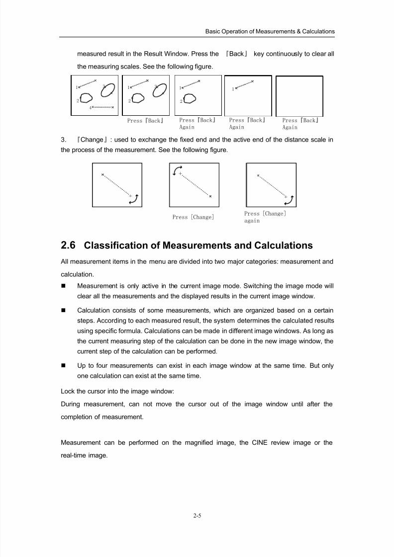
measured result in the Result Window. Press the 『Back』 key continuously to clear all
the measuring scales. See the following figure.
1
2
4
Press『Back』 Press『Back』
Again
311
2
3 1
2
Press『Back』
AgainPress『Back』
Again
3. 『Change』: used to exchange the fixed end and the active end of the distance scale in
the process of the measurement. See the following figure.
Press [Change]Press [Change]
again
2.6 Classification of Measurements and Calculations
All measurement items in the menu are divided into two major categories: measurement and
calculation.
Measurement is only active in the current image mode. Switching the image mode will
clear all the measurements and the displayed results in the current image window.
Calculation consists of some measurements, which are organized based on a certain
steps. According to each measured result, the system determines the calculated results
using specific formula. Calculations can be made in different image windows. As long as
the current measuring step of the calculation can be done in the new image window, the
current step of the calculation can be performed.
Up to four measurements can exist in each image window at the same time. But only
one calculation can exist at the same time.
Lock the cursor into the image window:
During measurement, can not move the cursor out of the image window until after the
completion of measurement.
Measurement can be performed on the magnified image, the CINE review image or the
real-time image.
8/11/2019 Mindray DP6600
http://slidepdf.com/reader/full/mindray-dp6600 35/113
Basic Operation of Measurements & Calculations
2-6
2.7 Attention
1. If measurement is to be done on a frozen image, unfreezing the image will clear up the
basic measurements information. After open the CIN file or FRM file, unfreezing the image will
clear up measurements, bodymarks and patient data.
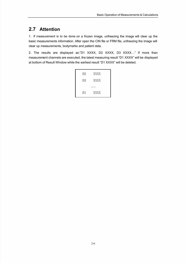
2. The results are displayed as:”D1 XXXX, D2 XXXX, D3 XXXX…” If more than
measurement channels are executed, the latest measuring result “D1 XXXX” will be displayed
at bottom of Result Window while the earliest result “D1 XXXX” will be deleted.
D2 XXXX
……
D3 XXXX
D1 XXXX
8/11/2019 Mindray DP6600
http://slidepdf.com/reader/full/mindray-dp6600 36/113
3-1
3B mode General Measurements &
Calculations
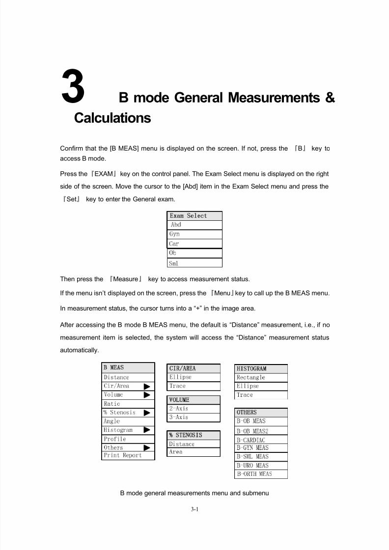
Confirm that the [B MEAS] menu is displayed on the screen. If not, press the 『B』 key to
access B mode.
Press the『EXAM』key on the control panel. The Exam Select menu is displayed on the right
side of the screen. Move the cursor to the [Abd] item in the Exam Select menu and press the
『Set』 key to enter the General exam.
Then press the 『Measure』 key to access measurement status.
If the menu isn’t displayed on the screen, press the『Menu』key to call up the B MEAS menu.
In measurement status, the cursor turns into a “+” in the image area.
After accessing the B mode B MEAS menu, the default is “Distance” measurement, i.e., if no
measurement item is selected, the system will access the “Distance” measurement status
automatically.
B mode general measurements menu and submenu
8/11/2019 Mindray DP6600
http://slidepdf.com/reader/full/mindray-dp6600 37/113
B mode General Measurements & Calculations
3-2
3.1 Distance
Function: to measure the distance between two points.
Measurement channels: 4
Measuring method:
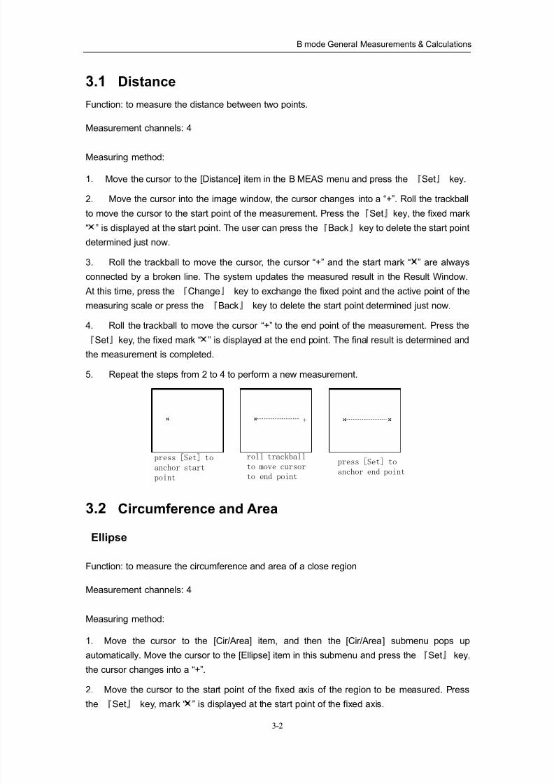
1. Move the cursor to the [Distance] item in the B MEAS menu and press the 『Set』 key.
2. Move the cursor into the image window, the cursor changes into a “+”. Roll the trackball
to move the cursor to the start point of the measurement. Press the『Set』key, the fixed mark
“ ” is displayed at the start point. The user can press the『Back』key to delete the start point
determined just now.
3. Roll the trackball to move the cursor, the cursor “+” and the start mark “ ” are always
connected by a broken line. The system updates the measured result in the Result Window.
At this time, press the 『Change』 key to exchange the fixed point and the active point of the
measuring scale or press the 『Back』 key to delete the start point determined just now.
4. Roll the trackball to move the cursor “+” to the end point of the measurement. Press the
『Set』key, the fixed mark “ ” is displayed at the end point. The final result is determined and
the measurement is completed.
5. Repeat the steps from 2 to 4 to perform a new measurement.
roll trackball
to move cursor
to end point
press [Set] to
anchor start
point
press [Set] to
anchor end point
+
3.2 Circumference and Area
Ellipse
Function: to measure the circumference and area of a close region
Measurement channels: 4
Measuring method:
1. Move the cursor to the [Cir/Area] item, and then the [Cir/Area] submenu pops up
automatically. Move the cursor to the [Ellipse] item in this submenu and press the 『Set』 key,
the cursor changes into a “+”.
2. Move the cursor to the start point of the fixed axis of the region to be measured. Press
the 『Set』 key, mark “ ” is displayed at the start point of the fixed axis.
8/11/2019 Mindray DP6600
http://slidepdf.com/reader/full/mindray-dp6600 38/113
B mode General Measurements & Calculations
3-3
3. Move the cursor to the end point of the fixed axis. At this time press the『Change』key to
exchange the start point and the end point of the fixed axis or press the 『Back』 key to return
to the previous step. The cursor “+” and the start point “ ” are always connected by a broken
line. Press the 『Set』 key, the mark “ ” is displayed at the end point of the fixed axis. An
ellipse is displayed on the screen.
4. Roll the trackball to adjust the length of the changeable axis of the ellipse to make the
ellipse rally with the region to be measured. Roll the trackball to left to shorten the changeable
axis or to right to increase the changeable axis. At this time press the『Back』key to return to
the previous step.
5. Press the 『Set』 key to confirm the ellipse region to be measured. The measured result
is displayed in the Result Window. The measurement ends.
6. Press the 『Set』 key to start a new measurement.
Trace
Function: to measure the circumference and area of a close region.
Measurement channels: 4
Measuring method:
1. Move the cursor to the [Cir/Area] item and the [Cir/Area] submenu pops up automatically.
Move the cursor then to the [Trace] item in the submenu, press the 『Set』 key and the cursor
changes into a “+”.
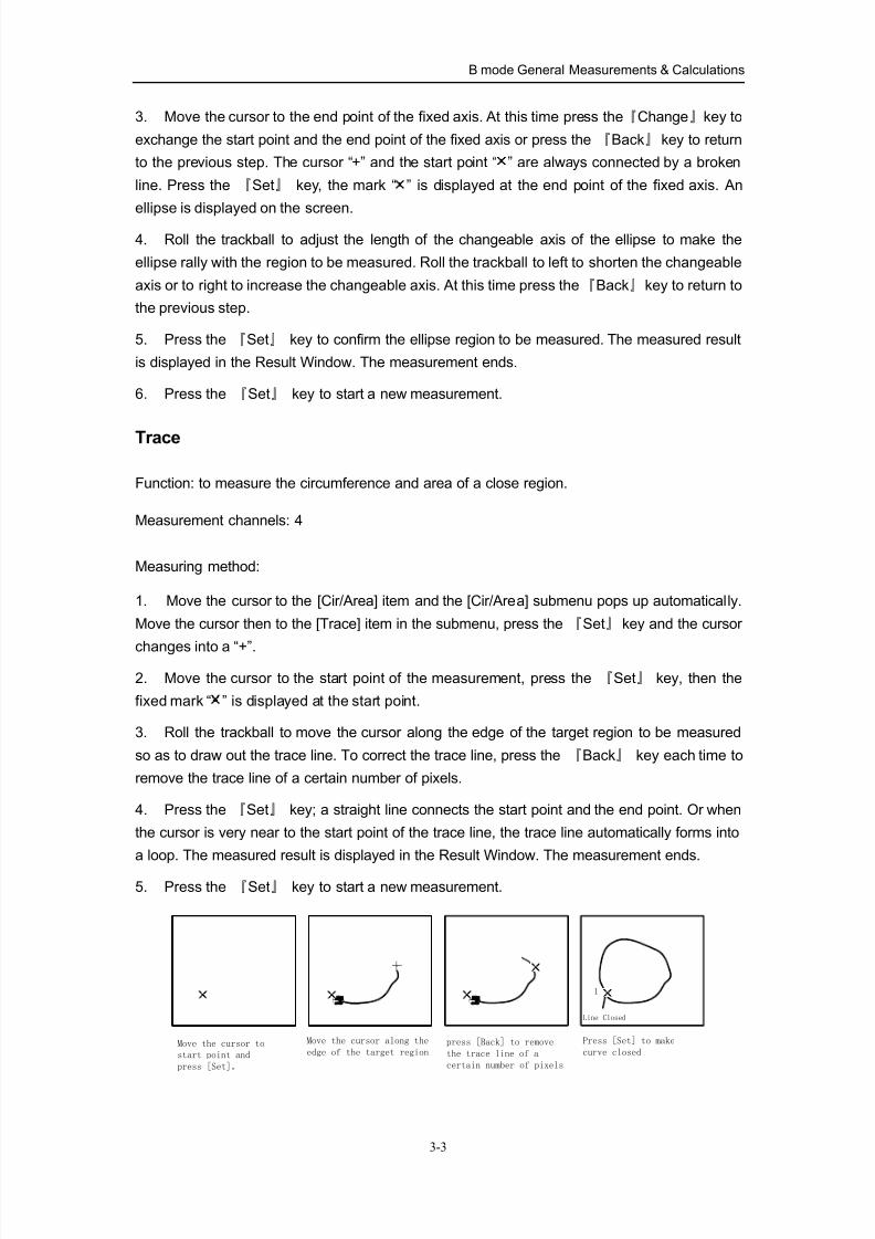
2. Move the cursor to the start point of the measurement, press the 『Set』 key, then the
fixed mark “ ” is displayed at the start point.
3. Roll the trackball to move the cursor along the edge of the target region to be measured
so as to draw out the trace line. To correct the trace line, press the 『Back』 key each time to
remove the trace line of a certain number of pixels.
4. Press the 『Set』 key; a straight line connects the start point and the end point. Or when
the cursor is very near to the start point of the trace line, the trace line automatically forms into
a loop. The measured result is displayed in the Result Window. The measurement ends.
5. Press the 『Set』 key to start a new measurement.
Move the cursor to
start point and
press [Set]。
Move the cursor along the
edge of the target regionpress [Back] to remove
the trace line of a
certain number of pixels
Press [Set] to make
curve closed
Line Closed
1
8/11/2019 Mindray DP6600
http://slidepdf.com/reader/full/mindray-dp6600 39/113
B mode General Measurements & Calculations
3-4
3.3 Volume
Function: to measure the volume of the target object.
Two methods are available to measure the volume: 2-axis, to measure the vertical profile of
the target, and 3-axis, to measure both the vertical profile and the horizontal profile of the
target.
The formula for 2-axis method:
V=(π/6)×A×B2
In the formula, A is the long axis of the ellipse and B the short axis.
The formula for 3-axis method:
V=(π/6)×A×B×M
In the formula, M is the length of the third axis.
Measurement channels: 1 for 3-axis, 4 for 2-axis.
Measuring method:
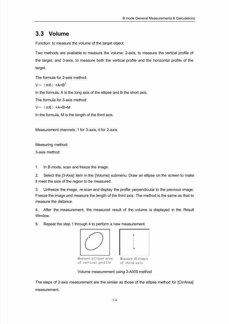
3-axis method:
1. In B mode, scan and freeze the image.
2. Select the [3-Axis] item in the [Volume] submenu. Draw an ellipse on the screen to make
it meet the size of the region to be measured.
3. Unfreeze the image, re-scan and display the profile perpendicular to the previous image.
Freeze the image and measure the length of the third axis. The method is the same as that to
measure the distance.
4. After the measurement, the measured result of the volume is displayed in the Result
Window.
5. Repeat the step 1 through 4 to perform a new measurement.
Measure ellipse area
of vertical profileMeasure distance
of third axis
Volume measurement using 3-AXIS method
The steps of 2-axis measurement are the similar as those of the ellipse method for [Cir/Area]measurement.
8/11/2019 Mindray DP6600
http://slidepdf.com/reader/full/mindray-dp6600 40/113
B mode General Measurements & Calculations
3-5
3.4 Ratio
Function: to measure and calculate the ratio between two measured distance values. The first
measured value is used as the numerator and the second measured value is used as the
denominator.
Measurement channels: 4
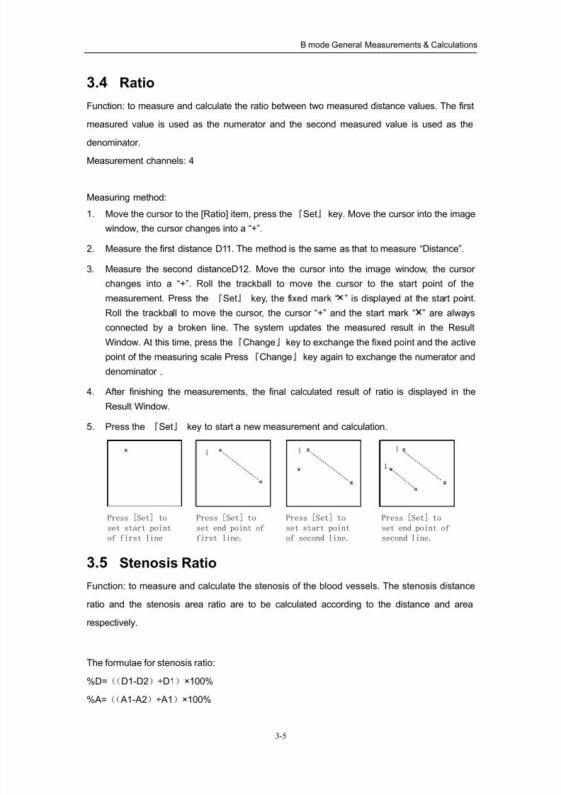
Measuring method:
1. Move the cursor to the [Ratio] item, press the『Set』 key. Move the cursor into the image
window, the cursor changes into a “+”.
2. Measure the first distance D11. The method is the same as that to measure “Distance”.
3. Measure the second distanceD12. Move the cursor into the image window, the cursor
changes into a “+”. Roll the trackball to move the cursor to the start point of the
measurement. Press the 『Set』 key, the fixed mark “ ” is displayed at the start point.
Roll the trackball to move the cursor, the cursor “+” and the start mark “ ” are always
connected by a broken line. The system updates the measured result in the Result
Window. At this time, press the『Change』key to exchange the fixed point and the active
point of the measuring scale Press『Change』key again to exchange the numerator and
denominator .
4. After finishing the measurements, the final calculated result of ratio is displayed in the
Result Window.
5. Press the 『Set』 key to start a new measurement and calculation.
1 1 1
1
Press [Set] to
set start point
of first line
Press [Set] to
set end point of
first line.
Press [Set] to
set start point
of second line.
Press [Set] to
set end point of
second line.
3.5 Stenosis Ratio
Function: to measure and calculate the stenosis of the blood vessels. The stenosis distance
ratio and the stenosis area ratio are to be calculated according to the distance and area
respectively.
The formulae for stenosis ratio:
%D=((D1-D2)÷D1)×100%
%A=(( A1-A2)÷A1)×100%
8/11/2019 Mindray DP6600
http://slidepdf.com/reader/full/mindray-dp6600 41/113
B mode General Measurements & Calculations
3-6
In the formulae, D1 and A1 respectively represent the distance and area at the non-stenosis
position. D2 and A2 respectively represent the distance and area at the stenosis position.
Stenosis distance ratio measurement channels: 1
Stenosis area ratio measurement channels: 4
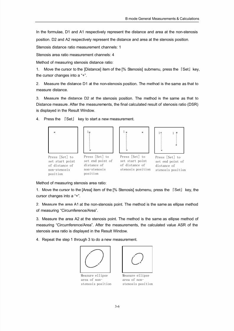
Method of measuring stenosis distance ratio:
1. Move the cursor to the [Distance] item of the [% Stenosis] submenu, press the『Set』key,
the cursor changes into a “+”.
2. Measure the distance D1 at the non-stenosis position. The method is the same as that to
measure distance.
3. Measure the distance D2 at the stenosis position. The method is the same as that to
Distance measure. After the measurements, the final calculated result of stenosis ratio (DSR)
is displayed in the Result Window.
4. Press the 『Set』 key to start a new measurement.
1 1 1 1
Press [Set] to
set start point
of distance of
non-stenosis
position
Press [Set] to
set end point of
distance of
non-stenosis
position
Press [Set] to
set start point
of distance of
stenosis position
Press [Set] to
set end point of
distance of
stenosis position
Method of measuring stenosis area ratio:
1. Move the cursor to the [Area] item of the [% Stenosis] submenu, press the 『Set』 key, the
cursor changes into a “+”.
2. Measure the area A1 at the non-stenosis point. The method is the same as ellipse method
of measuring “Circumference/Area”.
3. Measure the area A2 at the stenosis point. The method is the same as ellipse method of
measuring “Circumference/Area”. After the measurements, the calculated value ASR of the
stenosis area ratio is displayed in the Result Window.
4. Repeat the step 1 through 3 to do a new measurement.
Measure ellipse
area of non-
stenosis position
Measure ellipse
area of non-
stenosis position
8/11/2019 Mindray DP6600
http://slidepdf.com/reader/full/mindray-dp6600 42/113
B mode General Measurements & Calculations
3-7
3.6 Angle
Function: to measure the angle between two straight lines (0~180°).
Measurement channels: 4
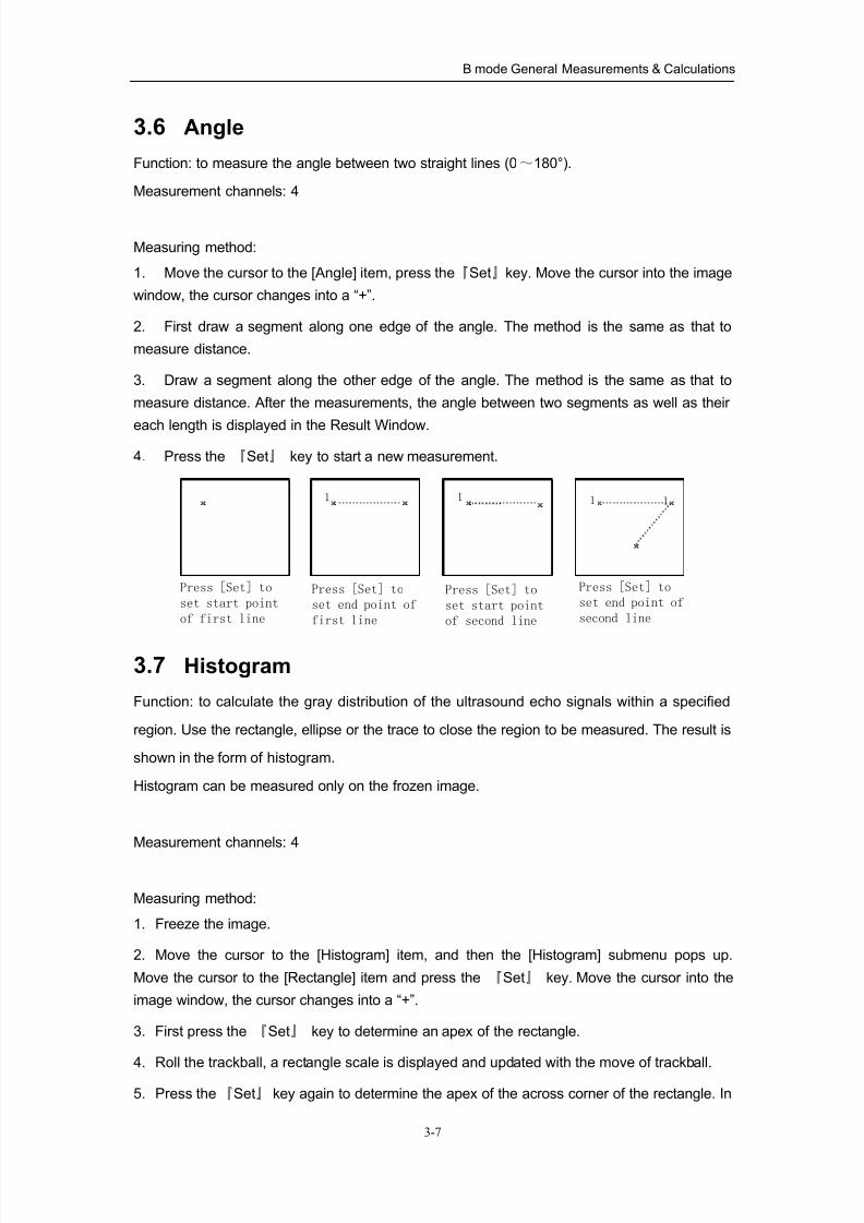
Measuring method:
1. Move the cursor to the [Angle] item, press the『Set』key. Move the cursor into the image
window, the cursor changes into a “+”.
2. First draw a segment along one edge of the angle. The method is the same as that to
measure distance.
3. Draw a segment along the other edge of the angle. The method is the same as that to
measure distance. After the measurements, the angle between two segments as well as their
each length is displayed in the Result Window.
4. Press the 『Set』 key to start a new measurement.
1 1 1 1
Press [Set] to
set start point
of first line
Press [Set] to
set end point of
first line
Press [Set] to
set end point of
second line
Press [Set] to
set start point
of second line
3.7 Histogram
Function: to calculate the gray distribution of the ultrasound echo signals within a specified
region. Use the rectangle, ellipse or the trace to close the region to be measured. The result is
shown in the form of histogram.
Histogram can be measured only on the frozen image.
Measurement channels: 4
Measuring method:
1. Freeze the image.
2. Move the cursor to the [Histogram] item, and then the [Histogram] submenu pops up.
Move the cursor to the [Rectangle] item and press the 『Set』 key. Move the cursor into the
image window, the cursor changes into a “+”.
3. First press the 『Set』 key to determine an apex of the rectangle.
4. Roll the trackball, a rectangle scale is displayed and updated with the move of trackball.
5. Press the『Set』 key again to determine the apex of the across corner of the rectangle. In
8/11/2019 Mindray DP6600
http://slidepdf.com/reader/full/mindray-dp6600 43/113
B mode General Measurements & Calculations
3-8
this way the rectangle area to be measured is determined. The calculated result of the
histogram is displayed in the image window.
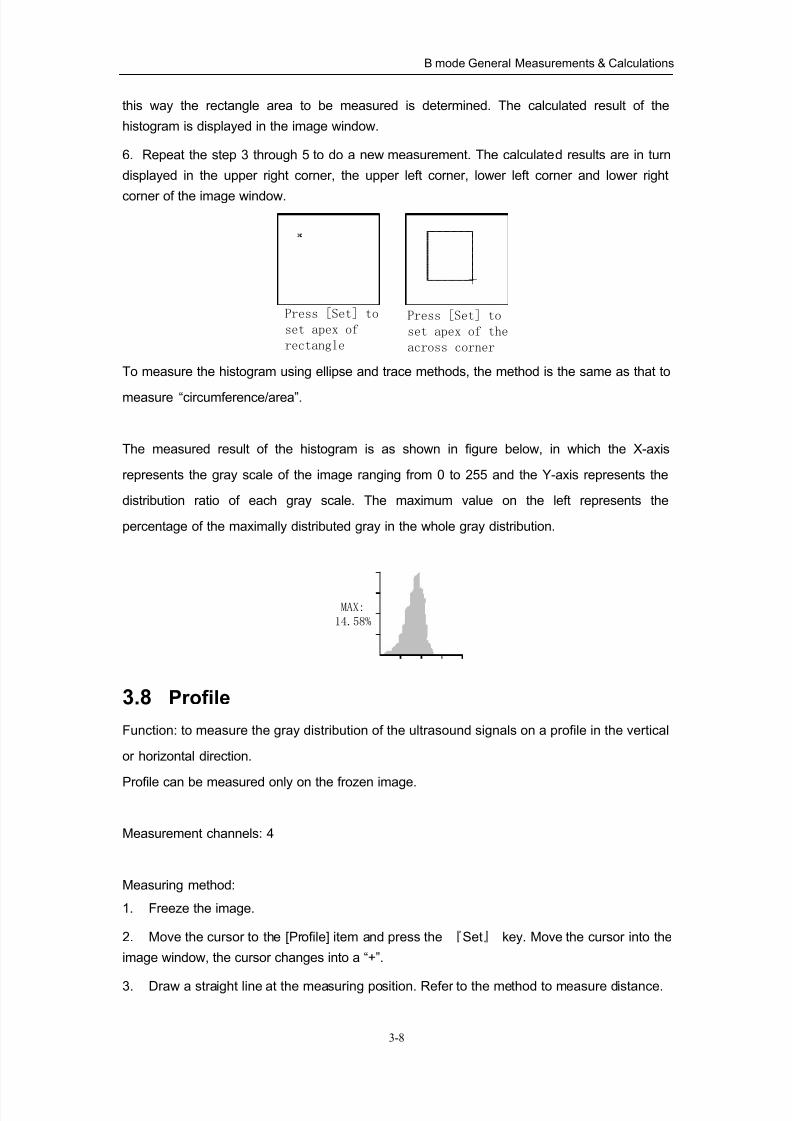
6. Repeat the step 3 through 5 to do a new measurement. The calculated results are in turn
displayed in the upper right corner, the upper left corner, lower left corner and lower right
corner of the image window.
Press [Set] to
set apex of the
across corner
Press [Set] to
set apex of
rectangle
To measure the histogram using ellipse and trace methods, the method is the same as that to
measure “circumference/area”.
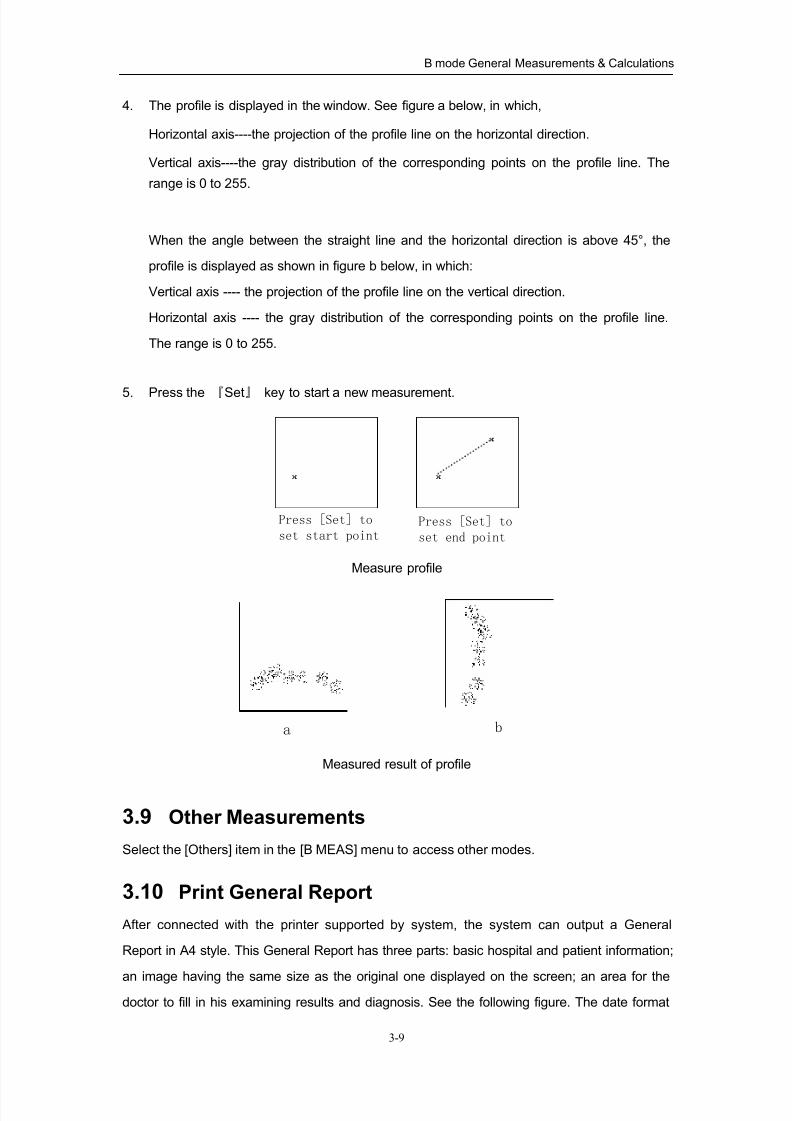
The measured result of the histogram is as shown in figure below, in which the X-axis
represents the gray scale of the image ranging from 0 to 255 and the Y-axis represents the
distribution ratio of each gray scale. The maximum value on the left represents the
percentage of the maximally distributed gray in the whole gray distribution.
MAX:
14.58%
3.8 Profile
Function: to measure the gray distribution of the ultrasound signals on a profile in the vertical
or horizontal direction.
Profile can be measured only on the frozen image.
Measurement channels: 4
Measuring method:
1. Freeze the image.
2. Move the cursor to the [Profile] item and press the 『Set』 key. Move the cursor into the
image window, the cursor changes into a “+”.
3. Draw a straight line at the measuring position. Refer to the method to measure distance.
8/11/2019 Mindray DP6600
http://slidepdf.com/reader/full/mindray-dp6600 44/113
B mode General Measurements & Calculations
3-9
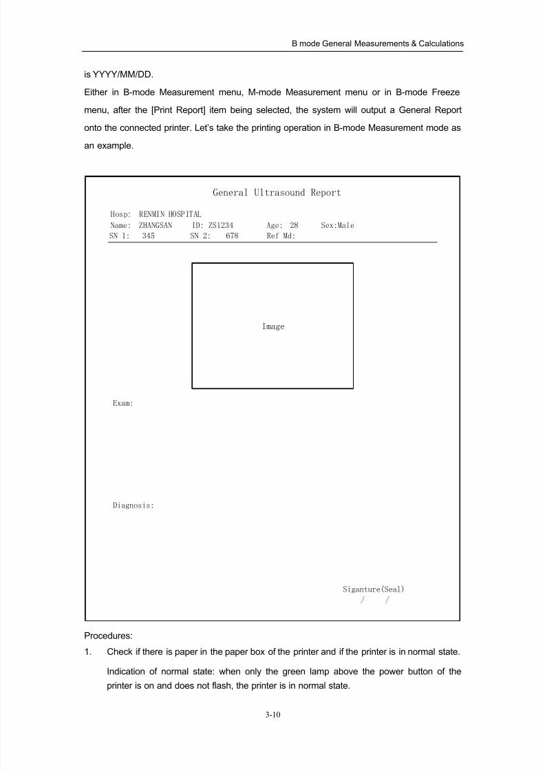
4. The profile is displayed in the window. See figure a below, in which,
Horizontal axis----the projection of the profile line on the horizontal direction.
Vertical axis----the gray distribution of the corresponding points on the profile line. The
range is 0 to 255.
When the angle between the straight line and the horizontal direction is above 45°, the
profile is displayed as shown in figure b below, in which:
Vertical axis ---- the projection of the profile line on the vertical direction.
Horizontal axis ---- the gray distribution of the corresponding points on the profile line.
The range is 0 to 255.
5. Press the 『Set』 key to start a new measurement.
Press [Set] to
set end point
Press [Set] to
set start point
Measure profile
a b
Measured result of profile
3.9 Other Measurements
Select the [Others] item in the [B MEAS] menu to access other modes.
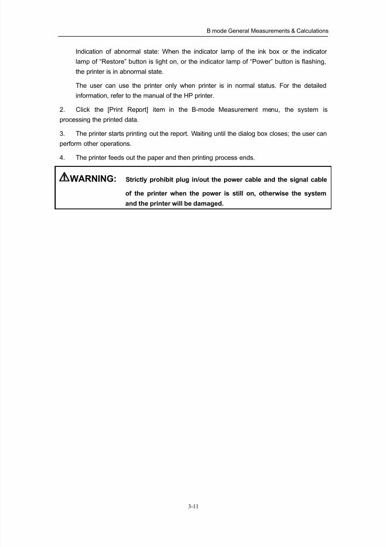
3.10 Print General Report
After connected with the printer supported by system, the system can output a General
Report in A4 style. This General Report has three parts: basic hospital and patient information;
an image having the same size as the original one displayed on the screen; an area for thedoctor to fill in his examining results and diagnosis. See the following figure. The date format
8/11/2019 Mindray DP6600
http://slidepdf.com/reader/full/mindray-dp6600 45/113
B mode General Measurements & Calculations
3-10
is YYYY/MM/DD.
Either in B-mode Measurement menu, M-mode Measurement menu or in B-mode Freeze
menu, after the [Print Report] item being selected, the system will output a General Report
onto the connected printer. Let’s take the printing operation in B-mode Measurement mode as
an example.
Exam:
Diagnosis:
Siganture(Seal)
/ /
Image
General Ultrasound Report
Hosp: RENMIN HOSPITAL
SN 1: SN 2: Ref Md:345 678
Name: ID: Age:ZHANGSAN ZS1234 28 Sex:Male
Procedures:
1. Check if there is paper in the paper box of the printer and if the printer is in normal state.
Indication of normal state: when only the green lamp above the power button of the
printer is on and does not flash, the printer is in normal state.
8/11/2019 Mindray DP6600
http://slidepdf.com/reader/full/mindray-dp6600 46/113
B mode General Measurements & Calculations
3-11
Indication of abnormal state: When the indicator lamp of the ink box or the indicator
lamp of “Restore” button is light on, or the indicator lamp of “Power” button is flashing,
the printer is in abnormal state.
The user can use the printer only when printer is in normal status. For the detailed
information, refer to the manual of the HP printer.
2. Click the [Print Report] item in the B-mode Measurement menu, the system is
processing the printed data.
3. The printer starts printing out the report. Waiting until the dialog box closes; the user can
perform other operations.
4. The printer feeds out the paper and then printing process ends.
WARNING: Strictly prohibit plug in/out the power cable and the signal cable
of the printer when the power is still on, otherwise the system
and the printer will be damaged.
8/11/2019 Mindray DP6600
http://slidepdf.com/reader/full/mindray-dp6600 47/113
4-1
4M Mode General Measurements &
Calculations
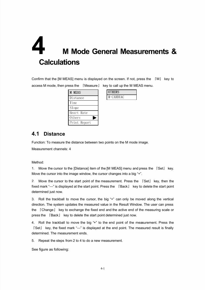
Confirm that the [M MEAS] menu is displayed on the screen. If not, press the 『M』 key to
access M mode, then press the 『Measure』 key to call up the M MEAS menu.
4.1 Distance
Function: To measure the distance between two points on the M mode image.
Measurement channels: 4
Method:
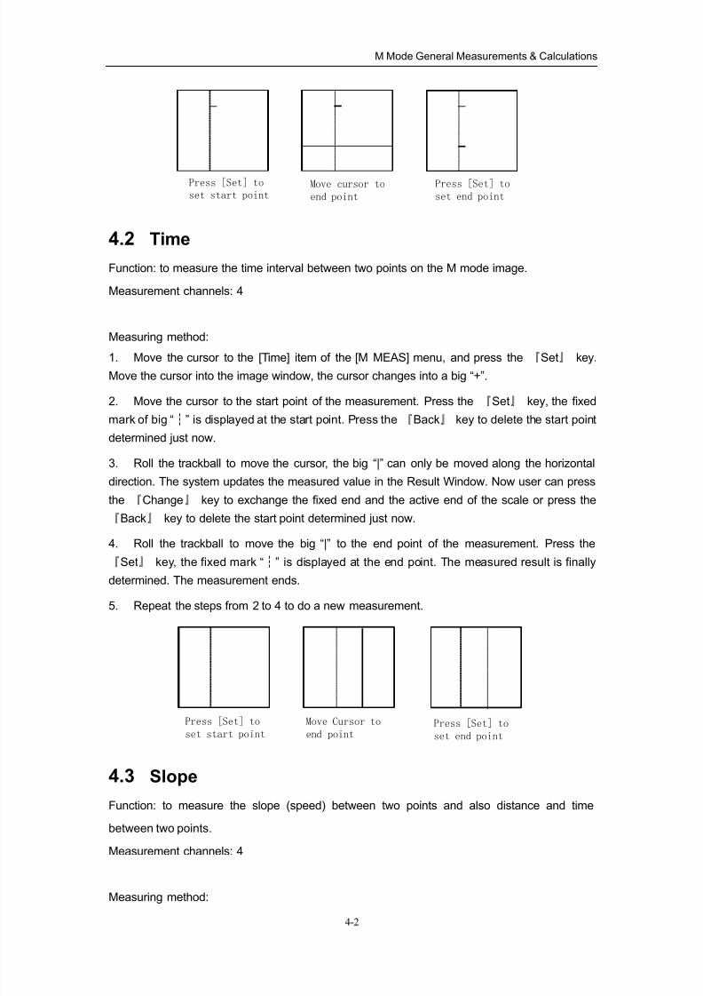
1. Move the cursor to the [Distance] item of the [M MEAS] menu and press the 『Set』 key.
Move the cursor into the image window, the cursor changes into a big “+”.
2. Move the cursor to the start point of the measurement. Press the 『Set』 key, then the
fixed mark “—” is displayed at the start point. Press the 『Back』 key to delete the start point
determined just now.
3. Roll the trackball to move the cursor, the big “+” can only be moved along the vertical
direction. The system updates the measured value in the Result Window. The user can press
the 『Change』 key to exchange the fixed end and the active end of the measuring scale or
press the 『Back』 key to delete the start point determined just now.
4. Roll the trackball to move the big “+” to the end point of the measurement. Press the
『Set』 key, the fixed mark “—” is displayed at the end point. The measured result is finally
determined. The measurement ends.
5. Repeat the steps from 2 to 4 to do a new measurement.
See figure as following:
8/11/2019 Mindray DP6600
http://slidepdf.com/reader/full/mindray-dp6600 48/113
M Mode General Measurements & Calculations
4-2
Move cursor to
end point
Press [Set] to
set start pointPress [Set] to
set end point
4.2 Time
Function: to measure the time interval between two points on the M mode image.
Measurement channels: 4
Measuring method:
1. Move the cursor to the [Time] item of the [M MEAS] menu, and press the 『Set』 key.
Move the cursor into the image window, the cursor changes into a big “+”.
2. Move the cursor to the start point of the measurement. Press the 『Set』 key, the fixed
mark of big “ ” is displayed at the start point. Press the┆ 『Back』 key to delete the start point
determined just now.
3. Roll the trackball to move the cursor, the big “|” can only be moved along the horizontal
direction. The system updates the measured value in the Result Window. Now user can press
the 『Change』 key to exchange the fixed end and the active end of the scale or press the
『Back』 key to delete the start point determined just now.
4. Roll the trackball to move the big “|” to the end point of the measurement. Press the
『Set』 key, the fixed mark “ ” is displayed at the end point. The meas┆ ured result is finally
determined. The measurement ends.
5. Repeat the steps from 2 to 4 to do a new measurement.
Move Cursor to
end point
Press [Set] to
set start pointPress [Set] to
set end point
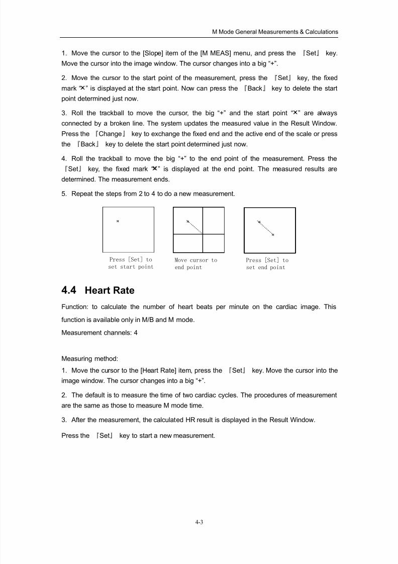
4.3 Slope
Function: to measure the slope (speed) between two points and also distance and time
between two points.
Measurement channels: 4
Measuring method:
8/11/2019 Mindray DP6600
http://slidepdf.com/reader/full/mindray-dp6600 49/113
M Mode General Measurements & Calculations
4-3
1. Move the cursor to the [Slope] item of the [M MEAS] menu, and press the 『Set』 key.
Move the cursor into the image window. The cursor changes into a big “+”.
2. Move the cursor to the start point of the measurement, press the 『Set』 key, the fixed
mark “ ” is displayed at the start point. Now can press the 『Back』 key to delete the start
point determined just now.
3. Roll the trackball to move the cursor, the big “+” and the start point “ ” are always
connected by a broken line. The system updates the measured value in the Result Window.
Press the 『Change』 key to exchange the fixed end and the active end of the scale or press
the 『Back』 key to delete the start point determined just now.
4. Roll the trackball to move the big “+” to the end point of the measurement. Press the
『Set』 key, the fixed mark “ ” is displayed at the end point. The measured results are
determined. The measurement ends.
5. Repeat the steps from 2 to 4 to do a new measurement.
Move cursor to
end point
Press [Set] to
set start pointPress [Set] to
set end point
4.4 Heart Rate
Function: to calculate the number of heart beats per minute on the cardiac image. This
function is available only in M/B and M mode.
Measurement channels: 4
Measuring method:
1. Move the cursor to the [Heart Rate] item, press the 『Set』 key. Move the cursor into the
image window. The cursor changes into a big “+”.
2. The default is to measure the time of two cardiac cycles. The procedures of measurementare the same as those to measure M mode time.
3. After the measurement, the calculated HR result is displayed in the Result Window.
Press the 『Set』 key to start a new measurement.
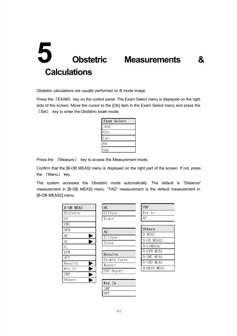
8/11/2019 Mindray DP6600
http://slidepdf.com/reader/full/mindray-dp6600 50/113
5-1
5Obstetric Measurements &
Calculations
Obstetric calculations are usually performed on B mode image.
Press the『EXAM』key on the control panel. The Exam Select menu is displayed on the right
side of the screen. Move the cursor to the [Ob] item in the Exam Select menu and press the
『Set』 key to enter the Obstetric exam mode.
Press the 『Measure』 key to access the Measurement mode.
Confirm that the [B-OB MEAS] menu is displayed on the right part of the screen. If not, press
the 『Menu』 key.
The system accesses the Obstetric mode automatically. The default is “Distance”
measurement in [B-OB MEAS] menu. “TAD” measurement is the default measurement in
[B-OB MEAS2] menu.
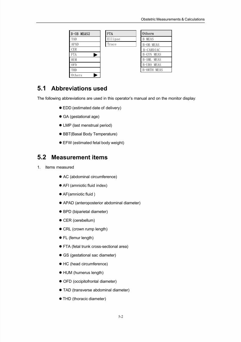
8/11/2019 Mindray DP6600
http://slidepdf.com/reader/full/mindray-dp6600 51/113
Obstetric Measurements & Calculations
5-2
TAD
CER
APAD
FTA
HUMOFD
THD
Others
Ellipse
Trace
B MEAS
B-OB MEAS
B-GYN MEAS
B-SML MEASB-URO MEAS
B-CARDIAC
B-ORTH MEAS
5.1 Abbreviations used
The following abbreviations are used in this operator’s manual and on the monitor display:
EDD (estimated date of delivery)
GA (gestational age)
LMP (last menstrual period)
BBT(Basal Body Temperature)
EFW (estimated fetal body weight)
5.2 Measurement items
1. Items measured
AC (abdominal circumference)
AFI (amniotic fluid index)
AF(amniotic fluid )
APAD (anteroposterior abdominal diameter)
BPD (biparietal diameter)
CER (cerebellum)
CRL (crown rump length)
FL (femur length)
FTA (fetal trunk cross-sectional area)
GS (gestational sac diameter)
HC (head circumference)
HUM (humerus length)
OFD (occipitofrontal diameter)
TAD (transverse abdominal diameter)
THD (thoracic diameter)
8/11/2019 Mindray DP6600
http://slidepdf.com/reader/full/mindray-dp6600 52/113
Obstetric Measurements & Calculations
5-3
2. Items calculated
EFW (estimated fetal weight)
GA (diagnosed gestational age or clinical gestational age)
3. Items key in
LMP (last menstrual period)
BBT(Basal Body Temperature)
FBP(fetus Biophysical profile)
5.3 Fetal Growth Measurements
The parameters given below are general indexes used to evaluate the fetal growth. After
measuring each parameter, the system will automatically calculate the GA based on the
measured results.
NOTE:
1. The GA here means diagnosed gestational age.
2. The formula that used in every measured item can be preset. Please refer
to “1.5 Preset Formula”.
3. Every measurement must be measured in the effect image area.
5.3.1 GS
Measurement Channels: 1
Use maximum diameter method to measure GS.
Method:
1. Move the cursor to the [GS] item, press the 『Set』 key and move the cursor into the
image window. The cursor changes into a “+”.
2. To measure GS, refer to the “Distance” measurement in B mode general measurements.
3. The measured result of GS is displayed in the Result Window. Whether GA is displayed
in the result window or not lies on the formula preset and whether LMP or BBT has been
entered or not before the measurement (Please refer to the details in the section “Preset
Formula”.).
4. Repeat the steps from 1 to 3 to do a new GS measurement.
8/11/2019 Mindray DP6600
http://slidepdf.com/reader/full/mindray-dp6600 53/113
Obstetric Measurements & Calculations
5-4
5.3.2 CRL
Measurement Channels: 1
Method:
1. Move the cursor to the [CRL] item. Press the 『Set』 key and move the cursor into the
image window. The cursor changes into a “+”.
2. To measure CRL, refer to the “Distance” measurement in B mode general
measurements.
3. The measured result of CRL is displayed in the Result Window. Whether GA is displayed
in the result window or not lies on whether LMP or BBT has been entered or not before the
measurement (Please refer to the details in the section “Preset Formula”.).
4. Repeat the steps from 1 to 3 to do a new CRL measurement.
5.3.3 BPD
Measurement Channels: 1
Method:
1. Move the cursor to [BPD] item. Press the『Set』 key and move the cursor into the image
window. The cursor changes into a “+”.
2. To measure BPD, refer to the “Distance” measurement in B mode general
measurements.
3. The measured result of BPD is displayed in the Result Window. Whether GA is displayed
in the result window or not lies on the formula preset and whether LMP or BBT has been
entered or not before the measurement (Please refer to the details in the section “Preset
Formula”.).
4. Repeat the steps from 1 to 3 to do a new BPD measurement.
5.3.4 HC
Two methods are available to measure HC. They are Ellipse method and Trace method.
Measurement Channels: 1
Method:
1. Move the cursor to the [HC] item. The [HC] submenu pops up. Move the cursor to [Ellipse]
or [Trace] in this submenu. Press the 『Set』 key, the cursor changes into a “+”.
8/11/2019 Mindray DP6600
http://slidepdf.com/reader/full/mindray-dp6600 54/113
Obstetric Measurements & Calculations
5-5
2. To measure HC, refer to the “Circumference and Area” measurement in B mode general
measurements.
3. The measured result of HC is displayed in the Result Window. Whether GA is displayed
in the result window or not lies on the formula preset and whether LMP or BBT has been
entered or not before the measurement (Please refer to the details in the section “PresetFormula”.).
4. Repeat the steps from 1 to 3 to do a new HC measurement.
5.3.5 AC
Two methods are available to measure AC. They are Ellipse method and Trace method.
Measurement Channels: 1
Method:
1. Move the cursor to the [AC] item. The [AC] submenu pops up. Move the cursor to [Ellipse]
or [Trace] item in this submenu. Press the 『Set』 key, the cursor changes into a “+”.
2. To measure AC, refer to the “Circumference and Area” measurement in B mode general
measurements.
3. The measured result of AC is displayed in the Result Window. Whether GA is displayed
in the result window or not lies on the formula preset and whether LMP or BBT has been
entered or not before the measurement (Please refer to the details in the section “Preset
Formula”.).
4. Repeat the steps from 1 to 3 to do a new AC measurement.
5.3.6 FL
Measurement Channels: 1
Method:
1. Move the cursor to the [FL] item. Press the 『Set』 key and move the cursor into the
image window. The cursor changes into a “+”.
2. To measure FL, refer to the “Distance” measurement in B mode general measurements.
3. The measured result of FL is displayed in the Result Window. Whether GA is displayed in
the result window or not lies on the formula preset and whether LMP or BBT has been
entered or not before the measurement (Please refer to the details in the section “Preset
Formula”.).
4. Repeat the steps from 1 to 3 to do a new FL measurement.
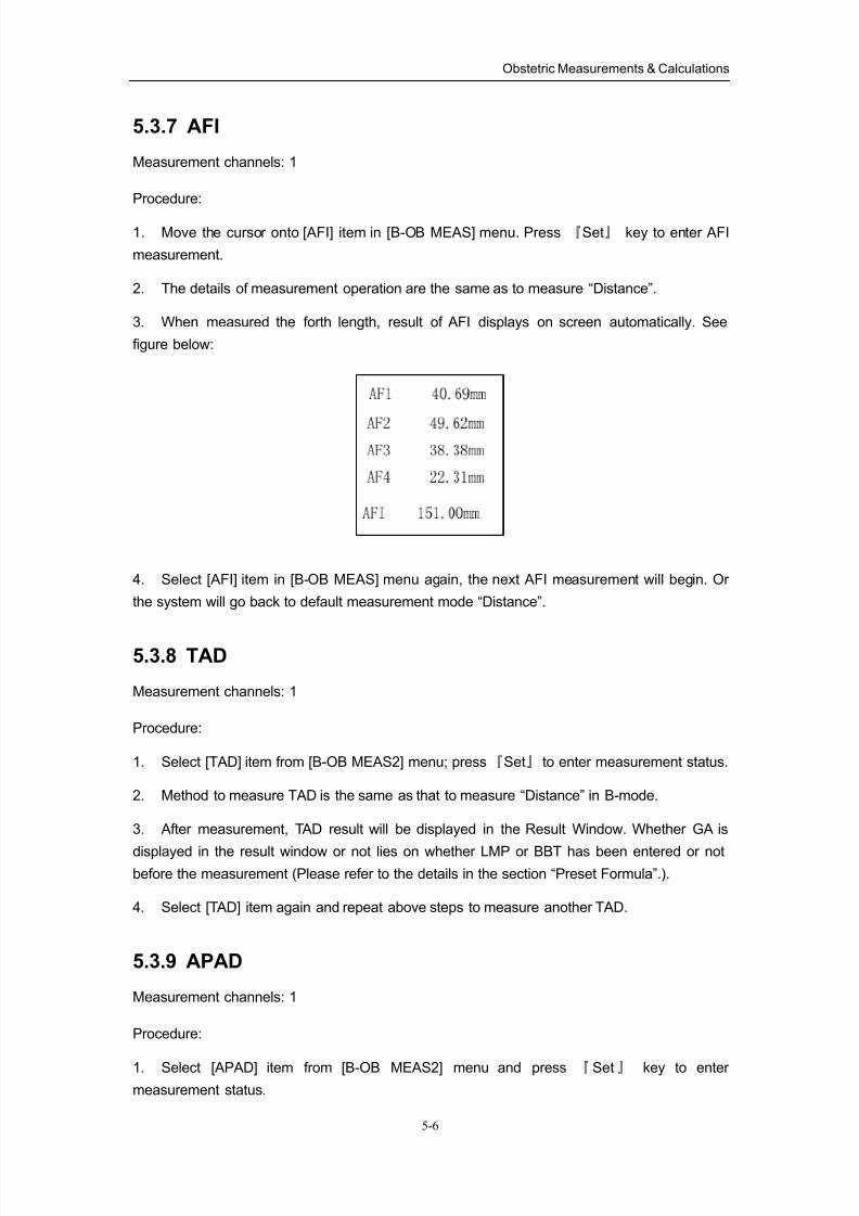
8/11/2019 Mindray DP6600
http://slidepdf.com/reader/full/mindray-dp6600 55/113
Obstetric Measurements & Calculations
5-6
5.3.7 AFI
Measurement channels: 1
Procedure:
1. Move the cursor onto [AFI] item in [B-OB MEAS] menu. Press 『Set』 key to enter AFI
measurement.
2. The details of measurement operation are the same as to measure “Distance”.
3. When measured the forth length, result of AFI displays on screen automatically. See
figure below:
4. Select [AFI] item in [B-OB MEAS] menu again, the next AFI measurement will begin. Or
the system will go back to default measurement mode “Distance”.
5.3.8 TAD
Measurement channels: 1
Procedure:
1. Select [TAD] item from [B-OB MEAS2] menu; press『Set』 to enter measurement status.
2. Method to measure TAD is the same as that to measure “Distance” in B-mode.
3. After measurement, TAD result will be displayed in the Result Window. Whether GA is
displayed in the result window or not lies on whether LMP or BBT has been entered or notbefore the measurement (Please refer to the details in the section “Preset Formula”.).
4. Select [TAD] item again and repeat above steps to measure another TAD.
5.3.9 APAD
Measurement channels: 1
Procedure:
1. Select [APAD] item from [B-OB MEAS2] menu and press 『Set』 key to enter
measurement status.
8/11/2019 Mindray DP6600
http://slidepdf.com/reader/full/mindray-dp6600 56/113
8/11/2019 Mindray DP6600
http://slidepdf.com/reader/full/mindray-dp6600 57/113
Obstetric Measurements & Calculations
5-8
1. Select [HUM] item from [B-OB MEAS2] menu and press『Set』key to enter measurement
status.
2. Method to measure HUM is the same as that to measure “Distance” in B-mode.
3. After measurement, HUM result will be displayed in the Result Window. Whether GA is
displayed in the result window or not lies on the formula preset and whether LMP or BBT has
been entered or not before the measurement (Please refer to the details in the section “Preset
Formula”.).
4. Select [HUM] item again and repeat above steps to measure another HUM. Otherwise;
the system will return to the default measurement item, i.e., TAD measurement.
5.3.13 OFD
Measurement channels: 1
Procedure:
1. Select [OFD] item from [B-OB MEAS2] menu and press『Set』key to enter measurement
status.
2. Method to measure OFD is the same as that to measure “Distance” in B-mode.
3. After measurement, OFD result will be displayed in the Result Window. Whether GA is
displayed in the result window or not lies on the formula preset and whether LMP or BBT has
been entered or not before the measurement (Please refer to the details in the section “Preset
Formula”.).
4. Select [OFD] item again and repeat above steps to measure another OFD. Otherwise;
the system will return to the default measurement item, i.e., TAD measurement.
5.3.14 THD
Measurement channels: 1
Procedure:
1. Select [THD] item from [B-OB MEAS2] menu and press 『Set』key to enter measurement
status.
2. Method to measure THD is the same as that to measure “Distance” in B-mode.
3. After measurement, THD result will be displayed in the Result Window. Whether GA is
displayed in the result window or not lies on whether LMP or BBT has been entered or not
before the measurement (Please refer to the details in the section “Preset Formula”.).
4. Select [THD] item again and repeat above steps to measure another THD. Otherwise; the
system will return to the default measurement item, i.e., TAD measurement.
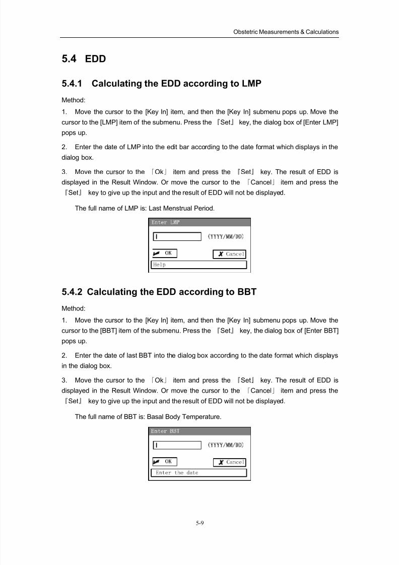
8/11/2019 Mindray DP6600
http://slidepdf.com/reader/full/mindray-dp6600 58/113
Obstetric Measurements & Calculations
5-9
5.4 EDD
5.4.1 Calculating the EDD according to LMP
Method:
1. Move the cursor to the [Key In] item, and then the [Key In] submenu pops up. Move the
cursor to the [LMP] item of the submenu. Press the 『Set』 key, the dialog box of [Enter LMP]
pops up.
2. Enter the date of LMP into the edit bar according to the date format which displays in the
dialog box.
3. Move the cursor to the 「Ok」 item and press the 『Set』 key. The result of EDD is
displayed in the Result Window. Or move the cursor to the 「Cancel」 item and press the
『Set』 key to give up the input and the result of EDD will not be displayed.
The full name of LMP is: Last Menstrual Period.
5.4.2 Calculating the EDD according to BBT
Method:
1. Move the cursor to the [Key In] item, and then the [Key In] submenu pops up. Move the
cursor to the [BBT] item of the submenu. Press the 『Set』 key, the dialog box of [Enter BBT]
pops up.
2. Enter the date of last BBT into the dialog box according to the date format which displays
in the dialog box.
3. Move the cursor to the 「Ok」 item and press the 『Set』 key. The result of EDD is
displayed in the Result Window. Or move the cursor to the 「Cancel」 item and press the
『Set』 key to give up the input and the result of EDD will not be displayed.
The full name of BBT is: Basal Body Temperature.
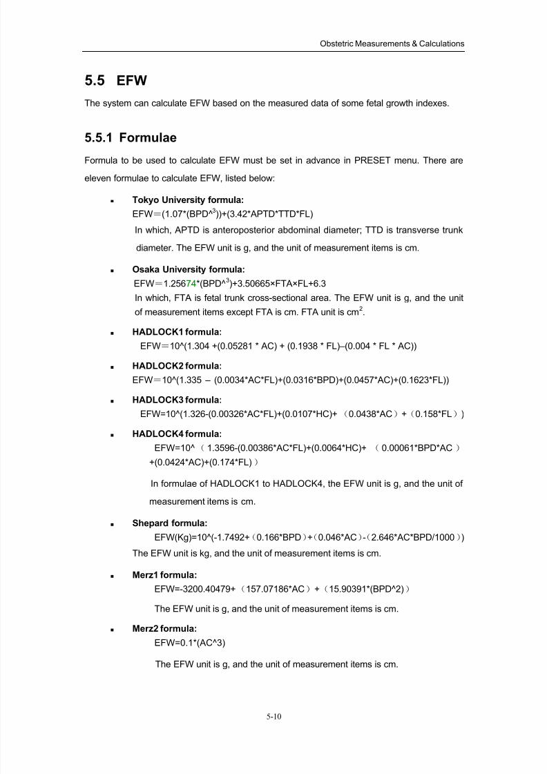
8/11/2019 Mindray DP6600
http://slidepdf.com/reader/full/mindray-dp6600 59/113
Obstetric Measurements & Calculations
5-10
5.5 EFW
The system can calculate EFW based on the measured data of some fetal growth indexes.
5.5.1 Formulae
Formula to be used to calculate EFW must be set in advance in PRESET menu. There are
eleven formulae to calculate EFW, listed below:
Tokyo University formula:
EFW=(1.07*(BPD^3))+(3.42*APTD*TTD*FL)
In which, APTD is anteroposterior abdominal diameter; TTD is transverse trunk
diameter. The EFW unit is g, and the unit of measurement items is cm.
Osaka University formula:EFW=1.25674*(BPD^
3)+3.50665×FTA×FL+6.3
In which, FTA is fetal trunk cross-sectional area. The EFW unit is g, and the unit
of measurement items except FTA is cm. FTA unit is cm2.
HADLOCK1 formula:
EFW=10^(1.304 +(0.05281 * AC) + (0.1938 * FL)–(0.004 * FL * AC))
HADLOCK2 formula:
EFW=10^(1.335 – (0.0034*AC*FL)+(0.0316*BPD)+(0.0457*AC)+(0.1623*FL))
HADLOCK3 formula:
EFW=10^(1.326-(0.00326*AC*FL)+(0.0107*HC)+(0.0438*AC)+(0.158*FL))
HADLOCK4 formula:
EFW=10^( 1.3596-(0.00386*AC*FL)+(0.0064*HC)+ ( 0.00061*BPD*AC )
+(0.0424*AC)+(0.174*FL))
In formulae of HADLOCK1 to HADLOCK4, the EFW unit is g, and the unit of
measurement items is cm.
Shepard formula:
EFW(Kg)=10^(-1.7492+(0.166*BPD)+(0.046*AC)-(2.646*AC*BPD/1000))
The EFW unit is kg, and the unit of measurement items is cm.
Merz1 formula:
EFW=-3200.40479+(157.07186*AC)+(15.90391*(BPD^2))
The EFW unit is g, and the unit of measurement items is cm.
Merz2 formula:
EFW=0.1*(AC^3)
The EFW unit is g, and the unit of measurement items is cm.
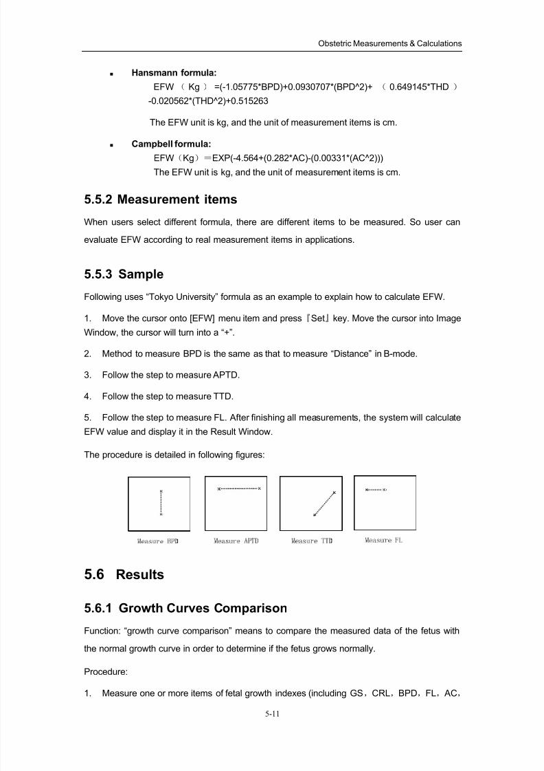
8/11/2019 Mindray DP6600
http://slidepdf.com/reader/full/mindray-dp6600 60/113
Obstetric Measurements & Calculations
5-11
Hansmann formula:
EFW ( Kg ) =(-1.05775*BPD)+0.0930707*(BPD^2)+ ( 0.649145*THD )
-0.020562*(THD^2)+0.515263
The EFW unit is kg, and the unit of measurement items is cm.
Campbell formula:
EFW(Kg)=EXP(-4.564+(0.282*AC)-(0.00331*(AC^2)))
The EFW unit is kg, and the unit of measurement items is cm.
5.5.2 Measurement items
When users select different formula, there are different items to be measured. So user can
evaluate EFW according to real measurement items in applications.
5.5.3 Sample
Following uses “Tokyo University” formula as an example to explain how to calculate EFW.
1. Move the cursor onto [EFW] menu item and press『Set』key. Move the cursor into Image
Window, the cursor will turn into a “+”.
2. Method to measure BPD is the same as that to measure “Distance” in B-mode.
3. Follow the step to measure APTD.
4. Follow the step to measure TTD.
5. Follow the step to measure FL. After finishing all measurements, the system will calculate
EFW value and display it in the Result Window.
The procedure is detailed in following figures:
5.6 Results
5.6.1 Growth Curves Comparison
Function: “growth curve comparison” means to compare the measured data of the fetus with
the normal growth curve in order to determine if the fetus grows normally.
Procedure:
1. Measure one or more items of fetal growth indexes (including GS,CRL,BPD,FL, AC,
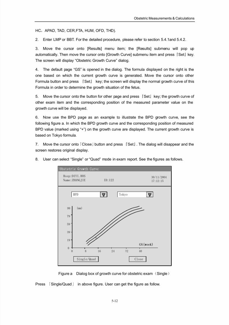
8/11/2019 Mindray DP6600
http://slidepdf.com/reader/full/mindray-dp6600 61/113
Obstetric Measurements & Calculations
5-12
HC, APAD, TAD, CER,FTA, HUM, OFD, THD).
2. Enter LMP or BBT. For the detailed procedure, please refer to section 5.4.1and 5.4.2.
3. Move the cursor onto [Results] menu item; the [Results] submenu will pop up
automatically. Then move the cursor onto [Growth Curve] submenu item and press『Set』key.
The screen will display “Obstetric Growth Curve” dialog.
4. The default page “GS” is opened in the dialog. The formula displayed on the right is the
one based on which the current growth curve is generated. Move the cursor onto other
Formula button and press 『Set』 key; the screen will display the normal growth curve of this
Formula in order to determine the growth situation of the fetus.
5. Move the cursor onto the button for other page and press『Set』key; the growth curve of
other exam item and the corresponding position of the measured parameter value on the
growth curve will be displayed.
6. Now use the BPD page as an example to illustrate the BPD growth curve, see the
following figure a. In which the BPD growth curve and the corresponding position of measured
BPD value (marked using “+”) on the growth curve are displayed. The current growth curve is
based on Tokyo formula.
7. Move the cursor onto「Close」button and press 『Set』. The dialog will disappear and the
screen restores original display.
8. User can select “Single” or “Quad” mode in exam report. See the figures as follows.
99
79
59
39
19
00 8 16 24 32 40
(mm)
+
Close
Hosp:DIYI.HOS
Name:ZHANGJIE ID:12330/11/2004
17:12:15
Single/Quad
BPD Tokyo
Figure a Dialog box of growth curve for obstetric exam(Single)
Press 「Single/Quad」 in above figure. User can get the figure as follow.
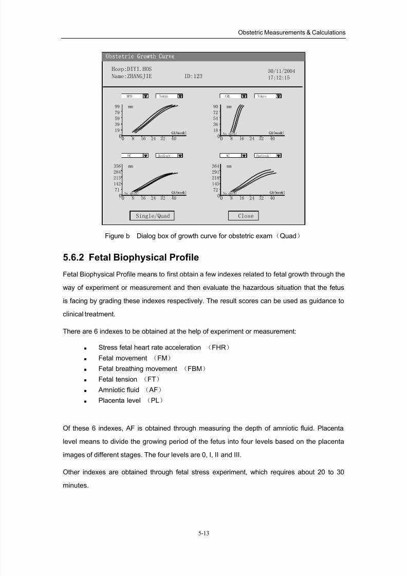
8/11/2019 Mindray DP6600
http://slidepdf.com/reader/full/mindray-dp6600 62/113
Obstetric Measurements & Calculations
5-13
Close
Hosp:DIYI.HOS
Name:ZHANGJIE ID:12330/11/2004
17:12:15
Single/Quad
99
79
59
39
19
00 8 16 24 32 40
mm
+
BPD Tokyo
356
284
213
142
71
00 8 16 24 32 40
mm
No data!
HC Hadlock
90
72
54
36
18
00 8 16 24 32 40
mm
No data!
CRL Tokyo
364
291
218
145
72
00 8 16 24 32 40
mm
No data!
AC Hadlock
Figure b Dialog box of growth curve for obstetric exam(Quad)
5.6.2 Fetal Biophysical Profile
Fetal Biophysical Profile means to first obtain a few indexes related to fetal growth through the
way of experiment or measurement and then evaluate the hazardous situation that the fetus
is facing by grading these indexes respectively. The result scores can be used as guidance to
clinical treatment.
There are 6 indexes to be obtained at the help of experiment or measurement:
Stress fetal heart rate acceleration (FHR)
Fetal movement (FM)
Fetal breathing movement (FBM)
Fetal tension (FT)
Amniotic fluid ( AF)
Placenta level(
PL)
Of these 6 indexes, AF is obtained through measuring the depth of amniotic fluid. Placenta
level means to divide the growing period of the fetus into four levels based on the placenta
images of different stages. The four levels are 0, I, II and III.
Other indexes are obtained through fetal stress experiment, which requires about 20 to 30
minutes.
8/11/2019 Mindray DP6600
http://slidepdf.com/reader/full/mindray-dp6600 63/113
Obstetric Measurements & Calculations
5-14
5.6.2.1 Measure the depth of amniotic fluid
Scale number: 1
Measure method:
1. Move the cursor to the [FBP] item in the menu, the [AF] submenu pops up automatically.
Move the cursor to the [AF] item and press 『Set』 key, the cursor then moves into the image
window and displays as a “+”.
2. Measure the depth of amniotic fluid. Refer to the method of “Distance” measurement in
B-mode Measurement.
3. After measurement, the depth of amniotic fluid will be displayed in the Result window. If
the scores of the fetal stress experiment have been entered, the total scores of fetal
biophysical profile will then be displayed in the Result window.
FBP grading criteria:
2 scores: max. amniotic fluid depth > 2 cm;
1 score: max. amniotic fluid depth is 1 to 2cm;
0: max. amniotic fluid depth < 1cm.
5.6.2.2 Enter scores for each index based on fetal stress experiment and
placenta level
FBP grading criteria:
1. FHR
Examining time: 20 minutes
FBP grading criteria:
2 scores: Condition is during fetal movements, FHR acceleration ≥15
times/minute and lasting time≥15S. It is 2 scores if the appearance of the situation
meeting the condition ≥5 times within 20 minutes;
1 score: Condition is during fetal movements, FHR acceleration≥15 times/minute
and lasting time ≥15s. It is 1 score if the appearance of the situation meeting the
condition is 1~4 times within 20 minutes;
0 score: during fetal movements, FHR acceleration≤1 times within 20 minutes
2. FM
Examining time: 30 minutes
FBP grading criteria:
2 scores: fetal movements ≥3 times within 30 minutes;
1 score: fetal movements is 1~2 times within 30 minutes;
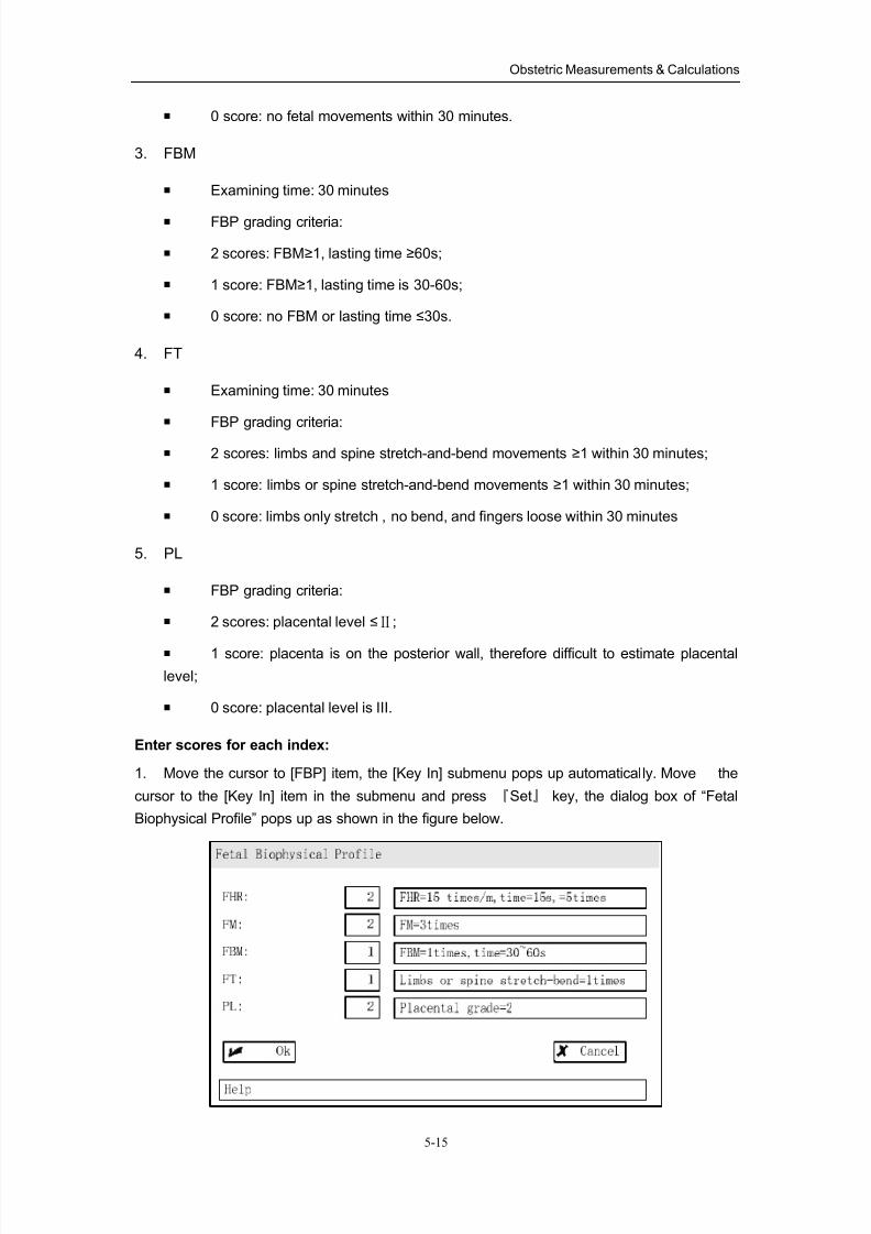
8/11/2019 Mindray DP6600
http://slidepdf.com/reader/full/mindray-dp6600 64/113
Obstetric Measurements & Calculations
5-15
0 score: no fetal movements within 30 minutes.
3. FBM
Examining time: 30 minutes
FBP grading criteria:
2 scores: FBM≥1, lasting time ≥60s;
1 score: FBM≥1, lasting time is 30-60s;
0 score: no FBM or lasting time ≤30s.
4. FT
Examining time: 30 minutes
FBP grading criteria:
2 scores: limbs and spine stretch-and-bend movements ≥1 within 30 minutes;
1 score: limbs or spine stretch-and-bend movements ≥1 within 30 minutes;
0 score: limbs only stretch , no bend, and fingers loose within 30 minutes
5. PL
FBP grading criteria:
2 scores: placental level ≤Ⅱ;
1 score: placenta is on the posterior wall, therefore difficult to estimate placental
level;
0 score: placental level is III.
Enter scores for each index:
1. Move the cursor to [FBP] item, the [Key In] submenu pops up automatically. Move the
cursor to the [Key In] item in the submenu and press 『Set』 key, the dialog box of “Fetal
Biophysical Profile” pops up as shown in the figure below.
8/11/2019 Mindray DP6600
http://slidepdf.com/reader/full/mindray-dp6600 65/113
Obstetric Measurements & Calculations
5-16
2. Based on the results of fetal stress experiment, set up the scores for each fetal index:
Move the cursor to one of the buttons used to adjust the scores of indexes, use『Set』 key or
『Back』key to change the value. The fetal stress experiment information corresponding to the
value is displayed in the Information bar on the right side.
3. After giving all indexes scores, press『Set』key on the「Ok」button to make the setupsinto effect and close the dialog box at the same time. If the AF value has been set up, the total
value of FBP will then be displayed in the Result window.
4. Or just press 『Set』 key on the「Cancel」 button to give up these setups and close the
dialog box at the same time.
5.6.3 FBP Report
After the depth of amniotic fluid being measured and the scores of fetal stress experiment and
the placenta level being entered, the system can automatically form FBP Report based on the
specified formula.
Formula: Vintzileos formula.
The data displayed in the report include:
Fetal growing state based on individual index:
Scores of individual index Growing condition
2 scores: Normal
1 score: Slight Abnormity
0 score: Obvious Abnormity
Total scores and general fetal growing condition
Total scores Growing condition
7-12 scores Normal fetus, chronic asphyxia’s risk is low.
3-6 scores Fetus chronic asphyxia’s risk is suspicious.
0-2 scores Fetus chronic asphyxia’s risk is highly suspicious.
FBP Report
Operating method:
Move the cursor to the [FBP Report] item in the [Result] menu and press 『Set』 key to open
the dialog box of “Fetal Biophysical Profile Report” as shown in the figure below.
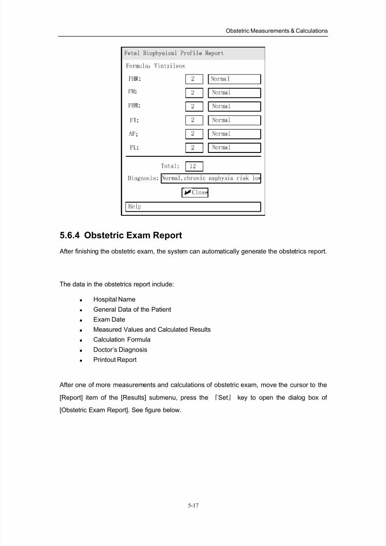
8/11/2019 Mindray DP6600
http://slidepdf.com/reader/full/mindray-dp6600 66/113
Obstetric Measurements & Calculations
5-17
5.6.4 Obstetric Exam Report
After finishing the obstetric exam, the system can automatically generate the obstetrics report.
The data in the obstetrics report include:
Hospital Name
General Data of the Patient
Exam Date
Measured Values and Calculated Results
Calculation Formula
Doctor’s Diagnosis
Printout Report
After one of more measurements and calculations of obstetric exam, move the cursor to the
[Report] item of the [Results] submenu, press the 『Set』 key to open the dialog box of
[Obstetric Exam Report]. See figure below.
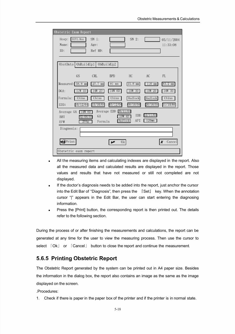
8/11/2019 Mindray DP6600
http://slidepdf.com/reader/full/mindray-dp6600 67/113
Obstetric Measurements & Calculations
5-18
All the measuring items and calculating indexes are displayed in the report. Also
all the measured data and calculated results are displayed in the report. Those
values and results that have not measured or still not completed are not
displayed.
If the doctor’s diagnosis needs to be added into the report, just anchor the cursor
into the Edit Bar of “Diagnosis”, then press the 『Set』 key. When the annotation
cursor “|” appears in the Edit Bar, the user can start entering the diagnosing
information.
Press the [Print] button, the corresponding report is then printed out. The details
refer to the following section.
During the process of or after finishing the measurements and calculations, the report can be
generated at any time for the user to view the measuring process. Then use the cursor to
select 「Ok」 or 「Cancel」 button to close the report and continue the measurement.
5.6.5 Printing Obstetric Report
The Obstetric Report generated by the system can be printed out in A4 paper size. Besides
the information in the dialog box, the report also contains an image as the same as the image
displayed on the screen.
.Procedures:1. Check if there is paper in the paper box of the printer and if the printer is in normal state.
8/11/2019 Mindray DP6600
http://slidepdf.com/reader/full/mindray-dp6600 68/113
Obstetric Measurements & Calculations
5-19
The user can use the printer only when printer is in normal status. For the detailed
information, refer to the instructions of the printer.
2. Open the dialog box of Obstetric Exam Report. Refer to chapter 5.6.4.
3. Click the [Print] button in the dialog box, some information would appear indicating that
the system is processing the printed data, please wait.
NOTE: After clicking the [Print] button, the entered data in the dialog box is then accepted
by the system, i.e. the function of clicking the [Print] button is the same as clicking
the 「Ok」 button, and then print.
4. The printer starts printing out the report. Waiting until the dialog box closes; the user can
perform other operations.
5. The printer feeds out the paper and then printing process ends.
WARNING: strictly prohibit plug in/out the power cable and the signal cable
of the printer when the power is still on, otherwise the system and
the printer will be damaged.
5.7 Others
Users can enter other application measurements through [Others] item from the [B-OB MEAS]
or [B-OB MEAS2] menu. Select corresponding item referring to the following figure and press
『Set』 key to switch it.
8/11/2019 Mindray DP6600
http://slidepdf.com/reader/full/mindray-dp6600 69/113
Obstetric Measurements & Calculations
5-20
5.8 References
GS Rempen A., 1991
Arztliche Fragen. Biometrie in der Fruhgraviditat (i.Trimenon): 425-430.
Hansmann M, Hackelöer BJ, Staudach AUltraschalldiagnostik in Geburtshilfe und Gynäkologie 1985
Hellman LM, Kobayashi M, Fillisti L, et al. Growth and development of thehuman fetus prior to the 20th week of gestation. Am J Obstet Gynecol 1969;103:784-800.
Studies on Fetal Growth and Functional Developments, Takashi Okai,Department of Obstetrics and Gynecology, Faculty of Medicine, University ofTokyo
ChinaWu Zhongyu etc.
Ultrasonography on Obstetrics and Gynecology. Tianjin Science &Technology Translation & Publishing Co.1995
CRL Rempen A., 1991 Arztliche Fragen. Biometrie in der Fruhgraviditat (i.Trimenon): 425-430.
Hansmann M, Hackelöer BJ, Staudach AUltraschalldiagnostik in Geburtshilfe und Gynäkologie 1985
Hadlock FP, et al. Fetal Crown-Rump Length: Reevaluation of Relation toMenstrual
Age (5-18 weeks) with High-Resolution Real-time US. Radiology182:501-505.
Jeanty P, Romero R. "Obstetrical Sonography", p. 56. New York, McGraw-Hill,1984.
Nelson L. Comparison of methods for determining crown-rump measurementby realtime ultrasound. J Clin Ultrasound February 1981; 9:67-70.
Robinson HP, Fleming JE. A critical evaluation of sonar crown rump lengthmeasurements. Br J Obstetric and Gynaecologic September 1975;82:702-710.
Fetal Growth Chart Using the Ultrasonotomographic TechniqueKeiichi Kurachi, Mineo AokiDepartment of Obstetrics and Gynecology, Osaka University Medical SchoolRevision 3 (September 1983)
Studies on Fetal Growth and Functional DevelopmentsTakashi OkaiDepartment of Obstetrics and Gynecology, Faculty of Medicine, University ofTokyo
ChinaWu Zhongyu etc.
Ultrasonography on Obstetrics and Gynecology. Tianjin Science &Technology Translation & Publishing Co.1995
8/11/2019 Mindray DP6600
http://slidepdf.com/reader/full/mindray-dp6600 70/113
Obstetric Measurements & Calculations
5-21
BPD Merz E., Werner G. & Ilan E. T., 1991Ultrasound in Gynaecology and Obstetrics Textbook and Atlas 312, 326-336.
Rempen A., 1991 Arztliche Fragen. Biometrie in der Fruhgraviditat (i.Trimenon): 425-430.
Hansmann M, Hackelöer BJ, Staudach AUltraschalldiagnostik in Geburtshilfe und Gynäkologie 1985
Hadlock FP, et al. Estimating Fetal Age: Computer-Assisted Analysis ofMultiple Fetal Growth Parameters. Radiology 1984; 152 (No. 2):499.
Jeanty P, Romero R. "Obstetrical Ultrasound." McGraw-Hill Book Company,1984, pp. 57-61.
Sabbagha RE, Hughey M. Standardization of sonar cephalometry andgestational age. Obstetrics and Gynecology October 1978; 52:402-406.
Kurtz AB, Wapner RJ, Kurtz RJ, et al. Analysis of bipariental diameter as an
accurate indicator of gestational age. J Clin Ultrasound 1980;8:319-326.
Fetal Growth Chart Using the Ultrasonotomographic Technique, KeiichiKurachi, Mineo Aoki, Department of Obstetrics and Gynecology, OsakaUniversity Medical School Revision 3 (September 1983)
Studies on Fetal Growth and Functional Developments, Takashi Okai,Department of Obstetrics and Gynecology, Faculty of Medicine, University ofTokyo
ChinaWu Zhongyu etc.
Ultrasonography on Obstetrics and Gynecology. Tianjin Science &
Technology Translation & Publishing Co.1995
HC Merz E., Werner G. & Ilan E. T., 1991Ultrasound in Gynecology and Obstetrics Textbook and Atlas 312, 326-336.
Hadlock FP, et al. Estimating Fetal Age: Computer-Assisted Analysis ofMultiple Fetal Growth Parameters. Radiology 1984; 152 (No. 2):499.
Jeanty P, Romero R. "Obstetrical Ultrasound." McGraw-Hill Book Company,1984.
Hansmann M, Hackelöer BJ, Staudach AUltraschalldiagnostik in Geburtshilfe und Gynäkologie 1985
AC Merz E., Werner G. & Ilan E. T., 1991Ultrasound in Gynaecology and Obstetrics Textbook and Atlas 312, 326-336.
Hadlock FP, et al. Estimating Fetal Age: Computer-Assisted Analysis ofMultiple Fetal Growth Parameters. Radiology 1984; 152 (No. 2):499.
Jeanty P, Romero R. A longitudinal study of fetal abdominal growth,"Obstetrical Ultrasound." MacGraw-Hill Book Company, 1984.
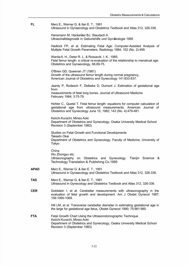
8/11/2019 Mindray DP6600
http://slidepdf.com/reader/full/mindray-dp6600 71/113
Obstetric Measurements & Calculations
5-22
FL Merz E., Werner G. & Ilan E. T., 1991Ultrasound in Gynaecology and Obstetrics Textbook and Atlas 312, 326-336.
Hansmann M, Hackelöer BJ, Staudach AUltraschalldiagnostik in Geburtshilfe und Gynäkologie 1995
Hadlock FP, et al. Estimating Fetal Age: Computer-Assisted Analysis ofMultiple Fetal Growth Parameters. Radiology 1984; 152 (No. 2):499.
Warda A. H., Deter R. L. & Rossavik, I. K., 1985.Fetal femur length: a critical re-evaluation of the relationship to menstrual age.Obstetrics and Gynaecology, 66,69-75.
O'Brien GD, Queenan JT (1981)Growth of the ultrasound femur length during normal pregnancy, American Journal of Obstetrics and Gynecology 141:833-837.
Jeanty P, Rodesch F, Delbeke D, Dumont J. Estimation of gestational agefrom
measurements of fetal long bones. Journal of Ultrasound MedicineFebruary 1984; 3:75-79.
Hohler C., Quetel T. Fetal femur length: equations for computer calculation ofgestational age from ultrasound measurements. American Journal ofObstetrics and Gynecology June 15, 1982; 143 (No. 4):479-481.
Keiichi Kurachi, Mineo AokiDepartment of Obstetrics and Gynecology, Osaka University Medical SchoolRevision 3 (September 1983)
Studies on Fetal Growth and Functional DevelopmentsTakashi Okai
Department of Obstetrics and Gynecology, Faculty of Medicine, University ofTokyo
ChinaWu Zhongyu etc.
Ultrasonography on Obstetrics and Gynecology. Tianjin Science &Technology Translation & Publishing Co.1995
APAD Merz E., Werner G. & Ilan E. T., 1991Ultrasound in Gynaecology and Obstetrics Textbook and Atlas 312, 326-336.
TAD Merz E., Werner G. & Ilan E. T., 1991Ultrasound in Gynecology and Obstetrics Textbook and Atlas 312, 326-336.
CER Goldstein I, et al. Cerebellar measurements with ultrasonography in theevaluation of fetal growth and development. Am J Obstet Gynecol 1987;156:1065-1069.
Hill LM, et al. Transverse cerebellar diameter in estimating gestational age inthe large for gestational age fetus, Obstet Gynecol 1990; 75:981-985.
FTA Fetal Growth Chart Using the Ultrasonotomographic TechniqueKeiichi Kurachi, Mineo AokiDepartment of Obstetrics and Gynecology, Osaka University Medical SchoolRevision 3 (September 1983)
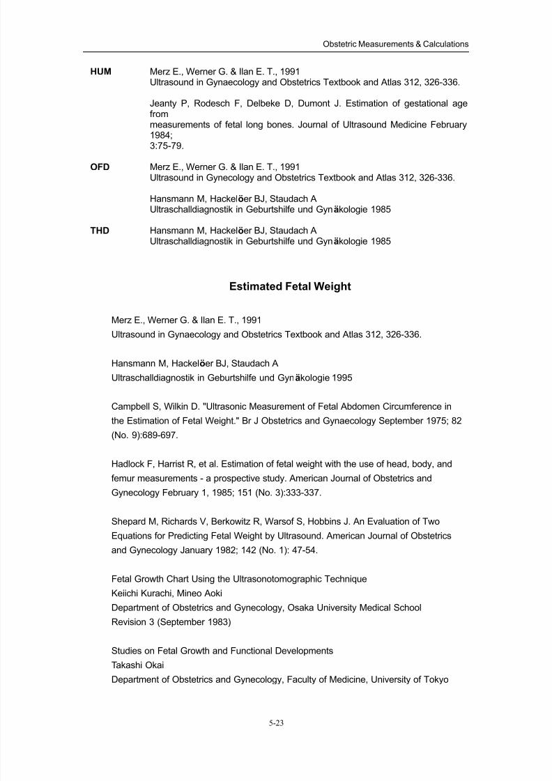
8/11/2019 Mindray DP6600
http://slidepdf.com/reader/full/mindray-dp6600 72/113
Obstetric Measurements & Calculations
5-23
HUM Merz E., Werner G. & Ilan E. T., 1991Ultrasound in Gynaecology and Obstetrics Textbook and Atlas 312, 326-336.
Jeanty P, Rodesch F, Delbeke D, Dumont J. Estimation of gestational agefrommeasurements of fetal long bones. Journal of Ultrasound Medicine February
1984;3:75-79.
OFD Merz E., Werner G. & Ilan E. T., 1991Ultrasound in Gynecology and Obstetrics Textbook and Atlas 312, 326-336.
Hansmann M, Hackelöer BJ, Staudach AUltraschalldiagnostik in Geburtshilfe und Gynäkologie 1985
THD Hansmann M, Hackelöer BJ, Staudach AUltraschalldiagnostik in Geburtshilfe und Gynäkologie 1985
Estimated Fetal Weight
Merz E., Werner G. & Ilan E. T., 1991
Ultrasound in Gynaecology and Obstetrics Textbook and Atlas 312, 326-336.
Hansmann M, Hackelöer BJ, Staudach A
Ultraschalldiagnostik in Geburtshilfe und Gynäkologie 1995
Campbell S, Wilkin D. "Ultrasonic Measurement of Fetal Abdomen Circumference inthe Estimation of Fetal Weight." Br J Obstetrics and Gynaecology September 1975; 82
(No. 9):689-697.
Hadlock F, Harrist R, et al. Estimation of fetal weight with the use of head, body, and
femur measurements - a prospective study. American Journal of Obstetrics and
Gynecology February 1, 1985; 151 (No. 3):333-337.
Shepard M, Richards V, Berkowitz R, Warsof S, Hobbins J. An Evaluation of Two
Equations for Predicting Fetal Weight by Ultrasound. American Journal of Obstetrics
and Gynecology January 1982; 142 (No. 1): 47-54.
Fetal Growth Chart Using the Ultrasonotomographic Technique
Keiichi Kurachi, Mineo Aoki
Department of Obstetrics and Gynecology, Osaka University Medical School
Revision 3 (September 1983)
Studies on Fetal Growth and Functional Developments
Takashi Okai
Department of Obstetrics and Gynecology, Faculty of Medicine, University of Tokyo
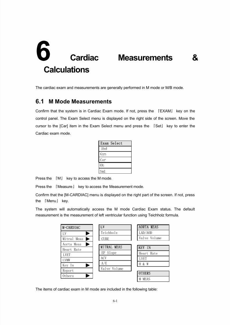
8/11/2019 Mindray DP6600
http://slidepdf.com/reader/full/mindray-dp6600 73/113
6-1
6Cardiac Measurements &
Calculations
The cardiac exam and measurements are generally performed in M mode or M/B mode.
6.1 M Mode Measurements
Confirm that the system is in Cardiac Exam mode. If not, press the 『EXAM』 key on the
control panel. The Exam Select menu is displayed on the right side of the screen. Move the
cursor to the [Car] item in the Exam Select menu and press the 『Set』 key to enter the
Cardiac exam mode.
Press the 『M』 key to access the M mode.
Press the 『Measure』 key to access the Measurement mode.
Confirm that the [M-CARDIAC] menu is displayed on the right part of the screen. If not, press
the 『Menu』 key.
The system will automatically access the M mode Cardiac Exam status. The default
measurement is the measurement of left ventricular function using Teichholz formula.
Mitral Meas
LV
Heart Rate
Aorta Meas
LVET
LVMW
Teichholz
CUBE
EF Slope
ACV
Key In
Report
Others
LAD/AOD
Valve Volume
Heart Rate
A/E
Valve Volume
M MEAS
LVET
H & W
The items of cardiac exam in M mode are included in the following table:
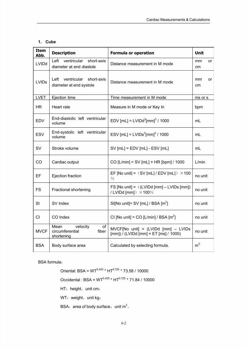
8/11/2019 Mindray DP6600
http://slidepdf.com/reader/full/mindray-dp6600 74/113
Cardiac Measurements & Calculations
6-2
1. Cube
Item Abb.
Description Formula or operation Unit
LVIDd Left ventricular short-axisdiameter at end diastole
Distance measurement in M mode mm orcm
LVIDsLeft ventricular short-axis
diameter at end systoleDistance measurement in M mode
mm or
cm
LVET Ejection time Time measurement in M mode ms or s
HR Heart rate Measure in M mode or Key In bpm
EDV
End-diastolic left ventricular
volume EDV [mL] = LVIDd
3
[mm]
3
/ 1000 mL
ESVEnd-systolic left ventricularvolume
ESV [mL] = LVIDs3[mm]
3 / 1000 mL
SV Stroke volume SV [mL] = EDV [mL] - ESV [mL] mL
CO Cardiac output CO [L/min] = SV [mL] × HR [bpm] / 1000 L/min
EF Ejection fractionEF [No unit] =(SV [mL] / EDV [mL])×100
% no unit
FS Fractional shorteningFS [No unit] =((LVIDd [mm] – LVIDs [mm])
/ LVIDd [mm])×100% no unit
SI SV Index SI[No unit]= SV [mL] / BSA [m2] no unit
CI CO Index CI [No unit] = CO [L/min] / BSA [m2] no unit
MVCFMean velocity ofcircumferential fibershortening
MVCF[No unit] = (LVIDd [mm] – LVIDs[mm]) / (LVIDd [mm] × ET [ms] / 1000)
no unit
BSA Body surface area Calculated by selecting formula. m2
BSA formula:
Oriental: BSA = WT0.425
* HT0.725
* 73.58 / 10000
Occidental : BSA = WT0.425
* HT0.725
* 71.84 / 10000
HT:height,unit cm;
WT:weight,unit kg;
BSA:area of body surface,unit m2。
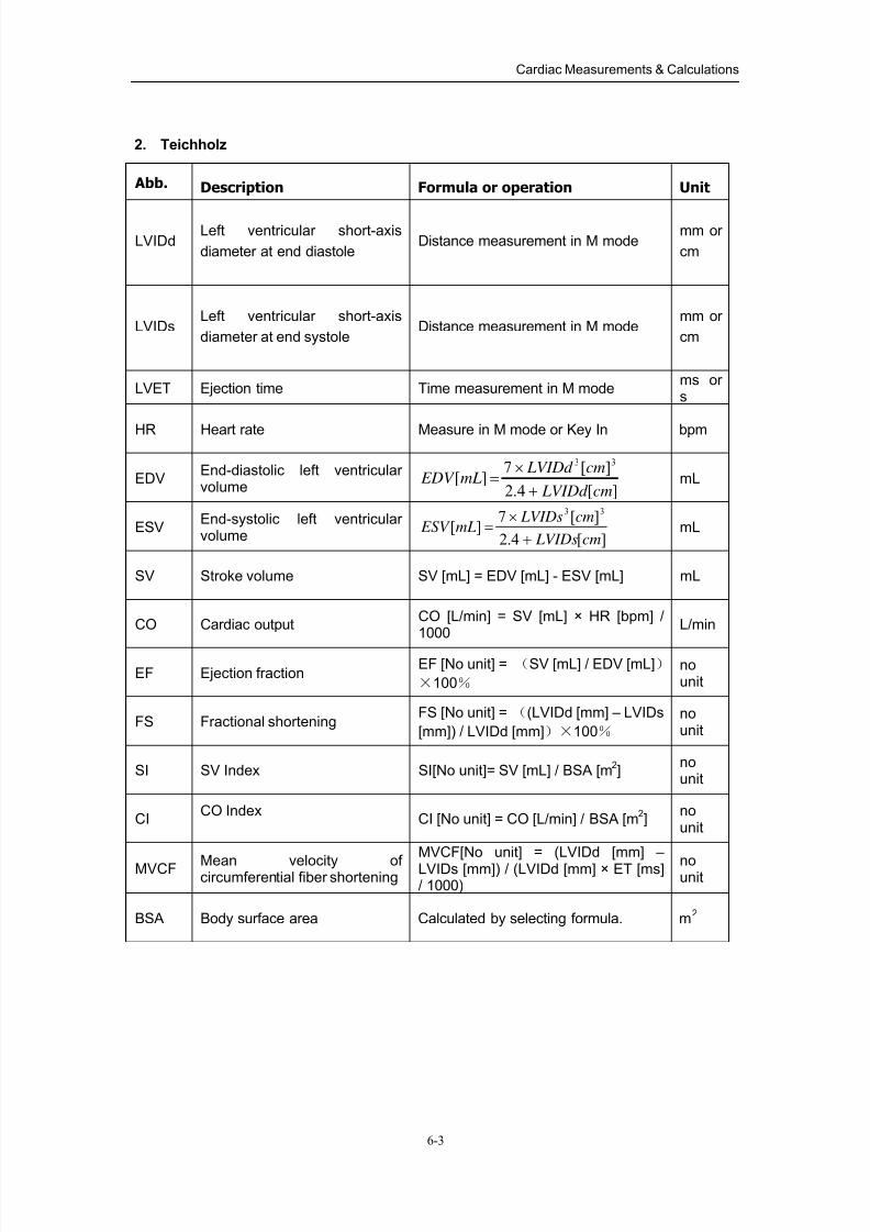
8/11/2019 Mindray DP6600
http://slidepdf.com/reader/full/mindray-dp6600 75/113
Cardiac Measurements & Calculations
6-3
2. Teichholz
Abb. Description Formula or operation Unit
LVIDd Left ventricular short-axis
diameter at end diastoleDistance measurement in M mode
mm or
cm
LVIDs Left ventricular short-axis
diameter at end systoleDistance measurement in M mode
mm or
cm
LVET Ejection time Time measurement in M modems ors
HR Heart rate Measure in M mode or Key In bpm
EDVEnd-diastolic left ventricularvolume ][4.2
][7][
33
cm LVIDd
cm LVIDd mL EDV
+
×=
mL
ESVEnd-systolic left ventricularvolume ][4.2
][7][
33
cm LVIDs
cm LVIDsmL ESV
+
×= mL
SV Stroke volume SV [mL] = EDV [mL] - ESV [mL] mL
CO Cardiac outputCO [L/min] = SV [mL] × HR [bpm] /1000
L/min
EF Ejection fractionEF [No unit] = (SV [mL] / EDV [mL])
×100%
nounit
FS Fractional shorteningFS [No unit] = ((LVIDd [mm] – LVIDs
[mm]) / LVIDd [mm])×100%
nounit
SI SV Index SI[No unit]= SV [mL] / BSA [m2]
nounit
CICO Index
CI [No unit] = CO [L/min] / BSA [m2]
nounit
MVCF Mean velocity ofcircumferential fiber shortening
MVCF[No unit] = (LVIDd [mm] –
LVIDs [mm]) / (LVIDd [mm] × ET [ms]/ 1000)
nounit
BSA Body surface area Calculated by selecting formula. m2
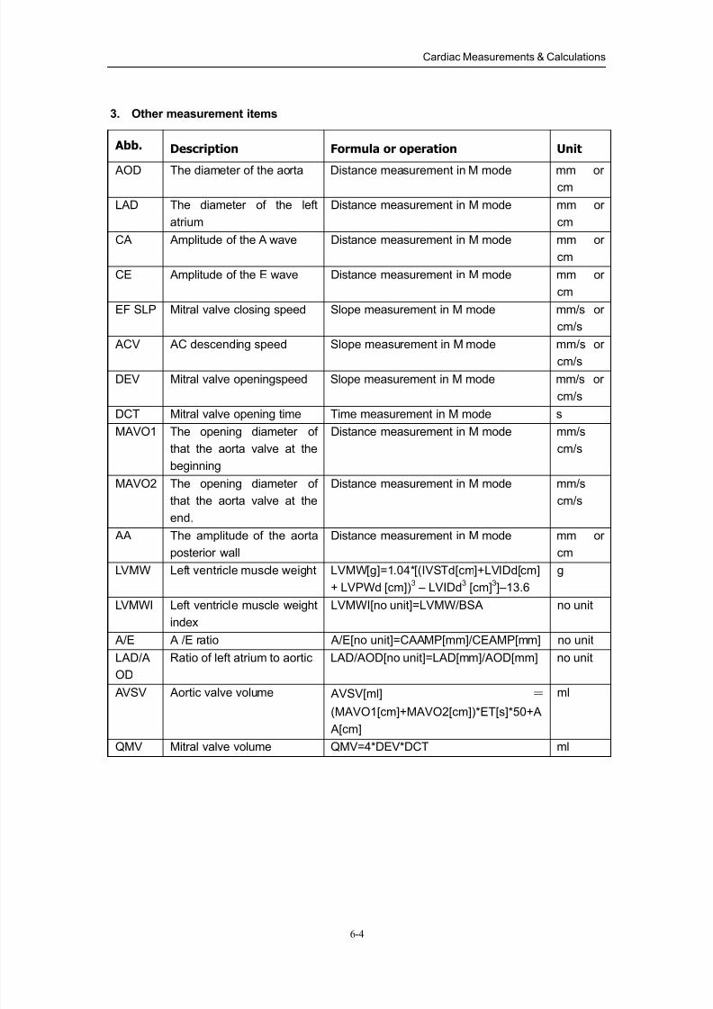
8/11/2019 Mindray DP6600
http://slidepdf.com/reader/full/mindray-dp6600 76/113
Cardiac Measurements & Calculations
6-4
3. Other measurement items
Abb. Description Formula or operation Unit
AOD The diameter of the aorta Distance measurement in M mode mm orcm
LAD The diameter of the left
atrium
Distance measurement in M mode mm or
cm
CA Amplitude of the A wave Distance measurement in M mode mm or
cm
CE Amplitude of the E wave Distance measurement in M mode mm or
cm
EF SLP Mitral valve closing speed Slope measurement in M mode mm/s or
cm/s
ACV AC descending speed Slope measurement in M mode mm/s or
cm/s
DEV Mitral valve openingspeed Slope measurement in M mode mm/s or
cm/s
DCT Mitral valve opening time Time measurement in M mode s
MAVO1 The opening diameter of
that the aorta valve at the
beginning
Distance measurement in M mode mm/s
cm/s
MAVO2 The opening diameter of
that the aorta valve at the
end.
Distance measurement in M mode mm/s
cm/s
AA The amplitude of the aorta
posterior wall
Distance measurement in M mode mm or
cm
LVMW Left ventricle muscle weight LVMW[g]=1.04*[(IVSTd[cm]+LVIDd[cm]
+ LVPWd [cm])3 – LVIDd
3 [cm]
3]–13.6
g
LVMWI Left ventricle muscle weight
index
LVMWI[no unit]=LVMW/BSA no unit
A/E A /E ratio A/E[no unit]=CAAMP[mm]/CEAMP[mm] no unit
LAD/A
OD
Ratio of left atrium to aortic LAD/AOD[no unit]=LAD[mm]/AOD[mm] no unit
AVSV Aortic valve volume AVSV[ml] =
(MAVO1[cm]+MAVO2[cm])*ET[s]*50+A
A[cm]
ml
QMV Mitral valve volume QMV=4*DEV*DCT ml
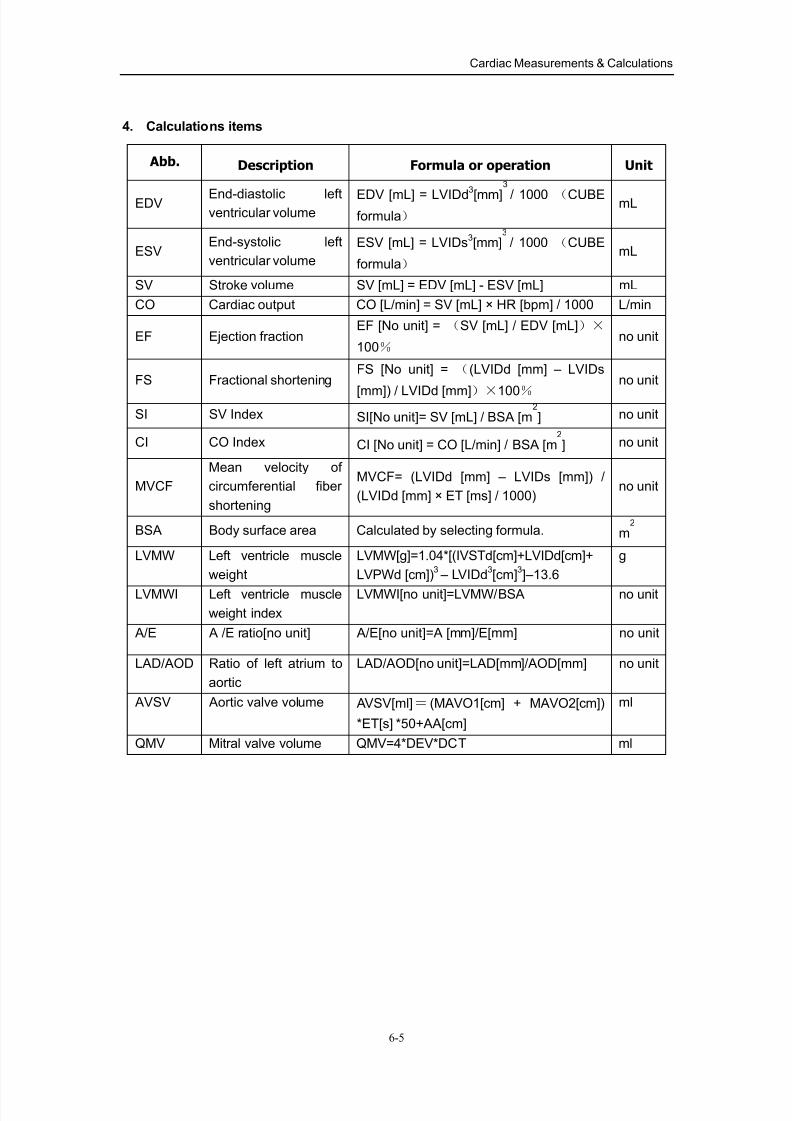
8/11/2019 Mindray DP6600
http://slidepdf.com/reader/full/mindray-dp6600 77/113
Cardiac Measurements & Calculations
6-5
4. Calculations items
Abb. Description Formula or operation Unit
EDV End-diastolic leftventricular volume
EDV [mL] = LVIDd3
[mm]
3
/ 1000 (CUBEformula)
mL
ESVEnd-systolic left
ventricular volume
ESV [mL] = LVIDs3[mm]
3
/ 1000 (CUBE
formula) mL
SV Stroke volume SV [mL] = EDV [mL] - ESV [mL] mL
CO Cardiac output CO [L/min] = SV [mL] × HR [bpm] / 1000 L/min
EF Ejection fractionEF [No unit] = (SV [mL] / EDV [mL])×
100% no unit
FS Fractional shorteningFS [No unit] = ((LVIDd [mm] – LVIDs
[mm]) / LVIDd [mm])×100%
no unit
SI SV Index SI[No unit]= SV [mL] / BSA [m2
] no unit
CI CO Index CI [No unit] = CO [L/min] / BSA [m2
] no unit
MVCF
Mean velocity of
circumferential fiber
shortening
MVCF= (LVIDd [mm] – LVIDs [mm]) /
(LVIDd [mm] × ET [ms] / 1000)no unit
BSA Body surface area Calculated by selecting formula. m2
LVMW Left ventricle muscle
weight
LVMW[g]=1.04*[(IVSTd[cm]+LVIDd[cm]+
LVPWd [cm])3 – LVIDd
3[cm]
3]–13.6
g
LVMWI Left ventricle muscle
weight index
LVMWI[no unit]=LVMW/BSA no unit
A/E A /E ratio[no unit] A/E[no unit]=A [mm]/E[mm] no unit
LAD/AOD Ratio of left atrium to
aortic
LAD/AOD[no unit]=LAD[mm]/AOD[mm] no unit
AVSV Aortic valve volume AVSV[ml]= (MAVO1[cm] + MAVO2[cm])
*ET[s] *50+AA[cm]
ml
QMV Mitral valve volume QMV=4*DEV*DCT ml
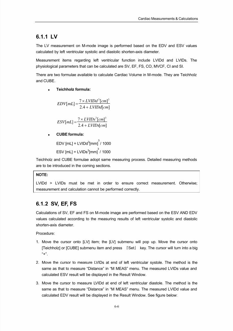
8/11/2019 Mindray DP6600
http://slidepdf.com/reader/full/mindray-dp6600 78/113
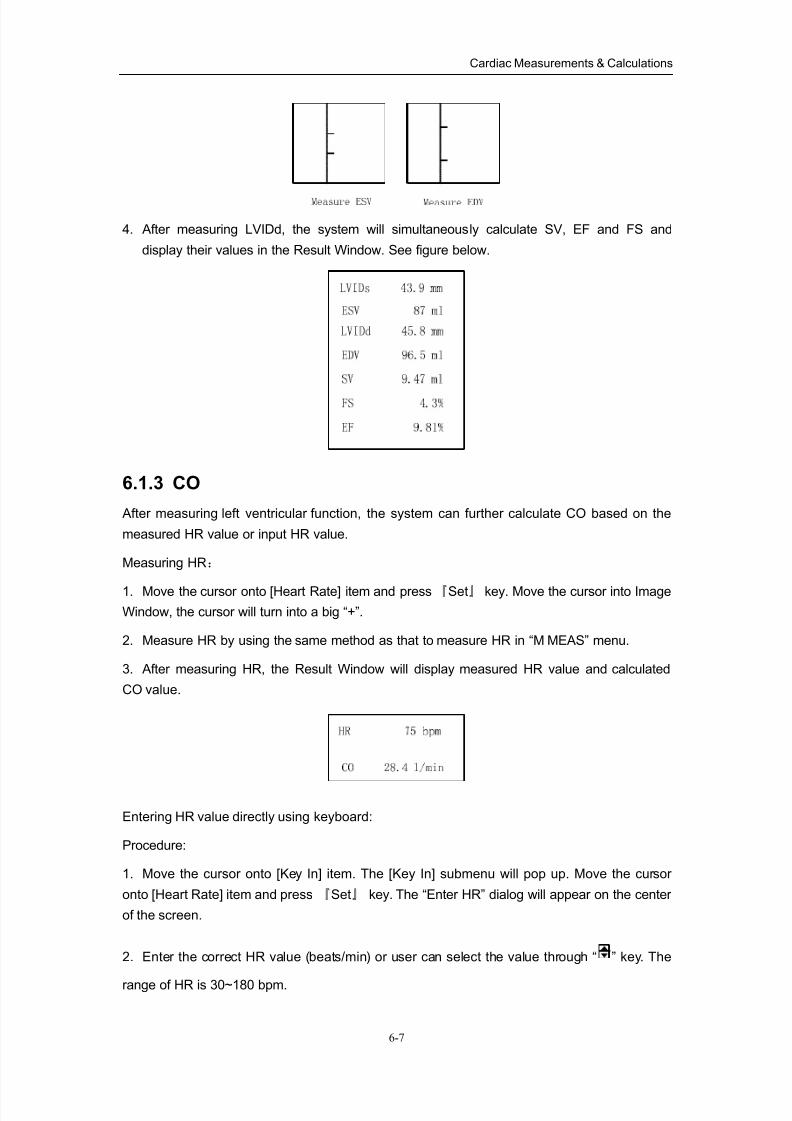
8/11/2019 Mindray DP6600
http://slidepdf.com/reader/full/mindray-dp6600 79/113
Cardiac Measurements & Calculations
6-7
4. After measuring LVIDd, the system will simultaneously calculate SV, EF and FS and
display their values in the Result Window. See figure below.
6.1.3 CO
After measuring left ventricular function, the system can further calculate CO based on the
measured HR value or input HR value.
Measuring HR:
1. Move the cursor onto [Heart Rate] item and press『Set』 key. Move the cursor into Image
Window, the cursor will turn into a big “+”.
2. Measure HR by using the same method as that to measure HR in “M MEAS” menu.
3. After measuring HR, the Result Window will display measured HR value and calculated
CO value.
Entering HR value directly using keyboard:
Procedure:
1. Move the cursor onto [Key In] item. The [Key In] submenu will pop up. Move the cursor
onto [Heart Rate] item and press 『Set』 key. The “Enter HR” dialog will appear on the center
of the screen.
2. Enter the correct HR value (beats/min) or user can select the value through “ ” key. The
range of HR is 30~180 bpm.
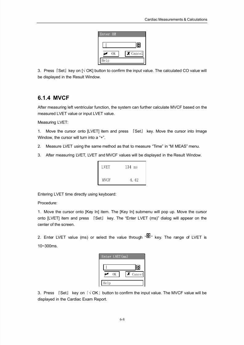
8/11/2019 Mindray DP6600
http://slidepdf.com/reader/full/mindray-dp6600 80/113
Cardiac Measurements & Calculations
6-8
3. Press『Set』key on [√ OK] button to confirm the input value. The calculated CO value will
be displayed in the Result Window.
6.1.4 MVCF
After measuring left ventricular function, the system can further calculate MVCF based on the
measured LVET value or input LVET value.
Measuring LVET:
1. Move the cursor onto [LVET] item and press 『Set』 key. Move the cursor into Image
Window, the cursor will turn into a “+”.
2. Measure LVET using the same method as that to measure “Time” in “M MEAS” menu.
3. After measuring LVET, LVET and MVCF values will be displayed in the Result Window.
Entering LVET time directly using keyboard:
Procedure:
1. Move the cursor onto [Key In] item. The [Key In] submenu will pop up. Move the cursor
onto [LVET] item and press 『Set』 key. The “Enter LVET (ms)” dialog will appear on the
center of the screen.
2. Enter LVET value (ms) or select the value through “ ” key. The range of LVET is
10~300ms.
Help
CancelOK
3. Press 『Set』 key on「√ OK」button to confirm the input value. The MVCF value will be
displayed in the Cardiac Exam Report.
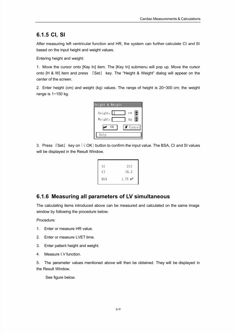
8/11/2019 Mindray DP6600
http://slidepdf.com/reader/full/mindray-dp6600 81/113
Cardiac Measurements & Calculations
6-9
6.1.5 CI, SI
After measuring left ventricular function and HR, the system can further calculate CI and SI
based on the input height and weight values.
Entering height and weight:
1. Move the cursor onto [Key In] item. The [Key In] submenu will pop up. Move the cursor
onto [H & W] item and press 『Set』 key. The “Height & Weight” dialog will appear on the
center of the screen.
2. Enter height (cm) and weight (kg) values. The range of height is 20~300 cm; the weight
range is 1~150 kg.
3. Press 『Set』 key on「√ OK」button to confirm the input value. The BSA, CI and SI values
will be displayed in the Result Window.
6.1.6 Measuring all parameters of LV simultaneous
The calculating items introduced above can be measured and calculated on the same image
window by following the procedure below.
Procedure:
1. Enter or measure HR value.
2. Enter or measure LVET time.
3. Enter patient height and weight.
4. Measure LV function.
5. The parameter values mentioned above will then be obtained. They will be displayed in
the Result Window.
See figure below.
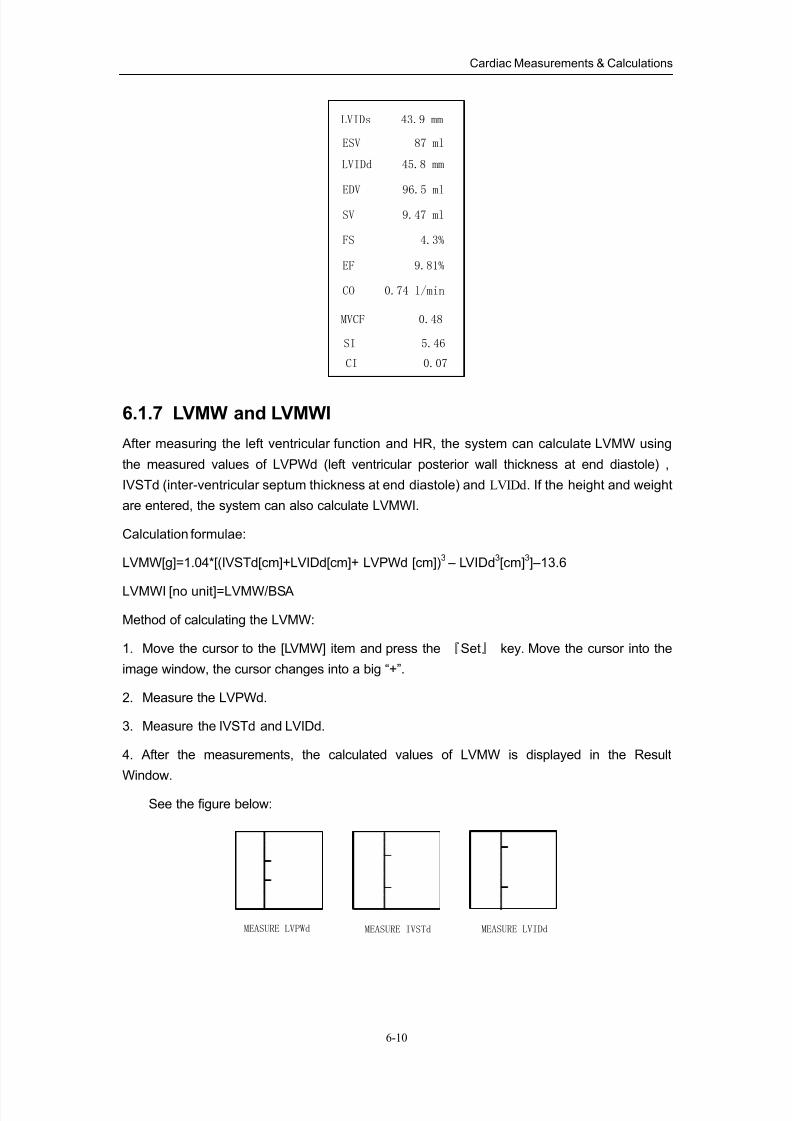
8/11/2019 Mindray DP6600
http://slidepdf.com/reader/full/mindray-dp6600 82/113
Cardiac Measurements & Calculations
6-10
LVIDs 43.9 mm
ESV 87 ml
LVIDd 45.8 mm
EDV 96.5 ml
SV 9.47 ml
FS 4.3%
EF 9.81%
CO 0.74 l/min
SI 5.46
MVCF 0.48
CI 0.07
6.1.7 LVMW and LVMWI
After measuring the left ventricular function and HR, the system can calculate LVMW using
the measured values of LVPWd (left ventricular posterior wall thickness at end diastole) ,
IVSTd (inter-ventricular septum thickness at end diastole) and LVIDd . If the height and weight
are entered, the system can also calculate LVMWI.
Calculation formulae:
LVMW[g]=1.04*[(IVSTd[cm]+LVIDd[cm]+ LVPWd [cm])3 – LVIDd
3[cm]
3]–13.6
LVMWI [no unit]=LVMW/BSA
Method of calculating the LVMW:
1. Move the cursor to the [LVMW] item and press the 『Set』 key. Move the cursor into the
image window, the cursor changes into a big “+”.
2. Measure the LVPWd.
3. Measure the IVSTd and LVIDd.
4. After the measurements, the calculated values of LVMW is displayed in the Result
Window.
See the figure below:
MEASURE IVSTdMEASURE LVPWd MEASURE LVIDd
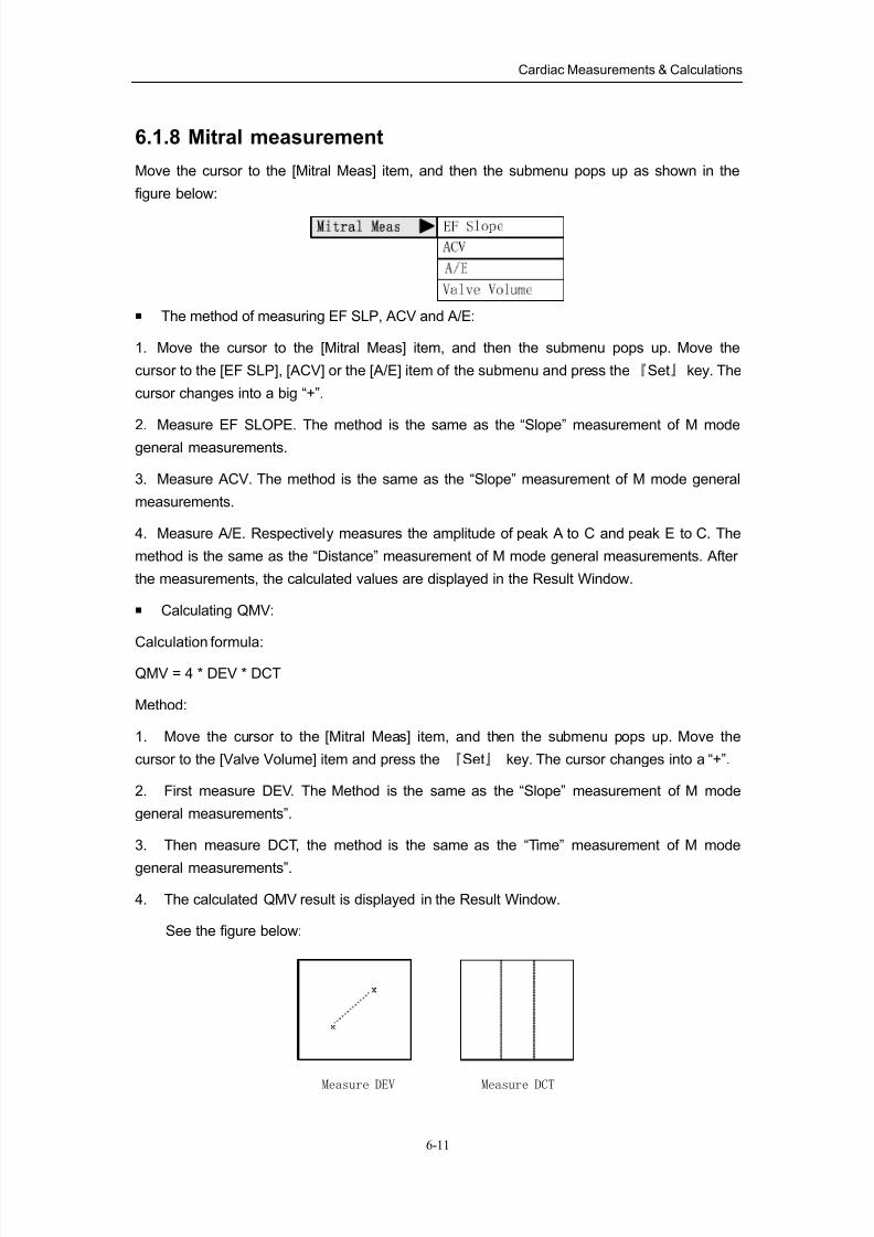
8/11/2019 Mindray DP6600
http://slidepdf.com/reader/full/mindray-dp6600 83/113
Cardiac Measurements & Calculations
6-11
6.1.8 Mitral measurement
Move the cursor to the [Mitral Meas] item, and then the submenu pops up as shown in the
figure below:
The method of measuring EF SLP, ACV and A/E:
1. Move the cursor to the [Mitral Meas] item, and then the submenu pops up. Move the
cursor to the [EF SLP], [ACV] or the [A/E] item of the submenu and press the『Set』 key. The
cursor changes into a big “+”.
2. Measure EF SLOPE. The method is the same as the “Slope” measurement of M mode
general measurements.
3. Measure ACV. The method is the same as the “Slope” measurement of M mode general
measurements.
4. Measure A/E. Respectively measures the amplitude of peak A to C and peak E to C. The
method is the same as the “Distance” measurement of M mode general measurements. After
the measurements, the calculated values are displayed in the Result Window.
Calculating QMV:
Calculation formula:
QMV = 4 * DEV * DCT
Method:
1. Move the cursor to the [Mitral Meas] item, and then the submenu pops up. Move the
cursor to the [Valve Volume] item and press the 『Set』 key. The cursor changes into a “+”.
2. First measure DEV. The Method is the same as the “Slope” measurement of M mode
general measurements”.
3. Then measure DCT, the method is the same as the “Time” measurement of M mode
general measurements”.
4. The calculated QMV result is displayed in the Result Window.
See the figure below:
Measure DCTMeasure DEV
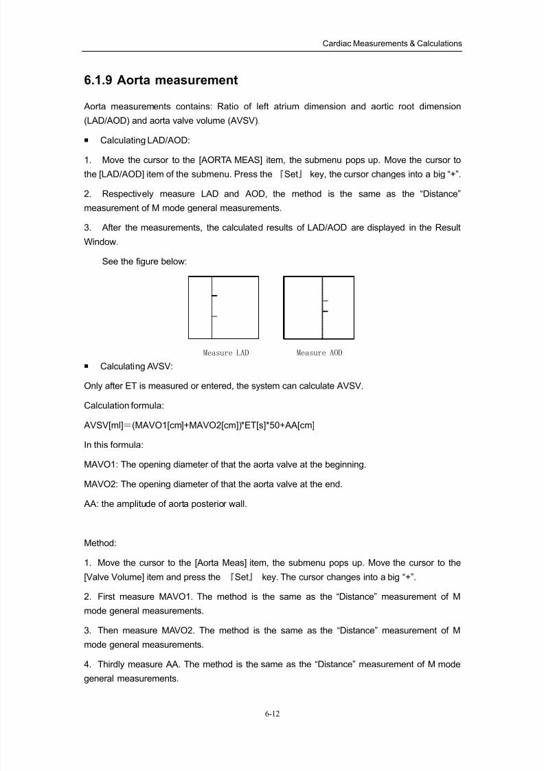
8/11/2019 Mindray DP6600
http://slidepdf.com/reader/full/mindray-dp6600 84/113
Cardiac Measurements & Calculations
6-12
6.1.9 Aorta measurement
Aorta measurements contains: Ratio of left atrium dimension and aortic root dimension
(LAD/AOD) and aorta valve volume (AVSV).
Calculating LAD/AOD:
1. Move the cursor to the [AORTA MEAS] item, the submenu pops up. Move the cursor to
the [LAD/AOD] item of the submenu. Press the 『Set』 key, the cursor changes into a big “+”.
2. Respectively measure LAD and AOD, the method is the same as the “Distance”
measurement of M mode general measurements.
3. After the measurements, the calculated results of LAD/AOD are displayed in the Result
Window.
See the figure below:
Measure AODMeasure LAD
Calculating AVSV:
Only after ET is measured or entered, the system can calculate AVSV.
Calculation formula:
AVSV[ml]=(MAVO1[cm]+MAVO2[cm])*ET[s]*50+AA[cm]
In this formula:
MAVO1: The opening diameter of that the aorta valve at the beginning.
MAVO2: The opening diameter of that the aorta valve at the end.
AA: the amplitude of aorta posterior wall.
Method:
1. Move the cursor to the [Aorta Meas] item, the submenu pops up. Move the cursor to the
[Valve Volume] item and press the 『Set』 key. The cursor changes into a big “+”.
2. First measure MAVO1. The method is the same as the “Distance” measurement of M
mode general measurements.
3. Then measure MAVO2. The method is the same as the “Distance” measurement of M
mode general measurements.
4. Thirdly measure AA. The method is the same as the “Distance” measurement of M mode
general measurements.
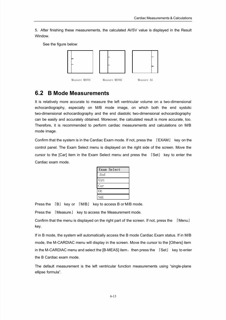
8/11/2019 Mindray DP6600
http://slidepdf.com/reader/full/mindray-dp6600 85/113
Cardiac Measurements & Calculations
6-13
5. After finishing these measurements, the calculated AVSV value is displayed in the Result
Window.
See the figure below:
Measure AAMeasure MAV02Measure MAVO1
6.2 B Mode Measurements
It is relatively more accurate to measure the left ventricular volume on a two-dimensional
echocardiography, especially on M/B mode image, on which both the end systolic
two-dimensional echocardiography and the end diastolic two-dimensional echocardiography
can be easily and accurately obtained. Moreover, the calculated result is more accurate, too.
Therefore, it is recommended to perform cardiac measurements and calculations on M/B
mode image.
Confirm that the system is in the Cardiac Exam mode. If not, press the 『EXAM』 key on the
control panel. The Exam Select menu is displayed on the right side of the screen. Move the
cursor to the [Car] item in the Exam Select menu and press the 『Set』 key to enter the
Cardiac exam mode.
Press the 『B』 key or 『M/B』 key to access B or M/B mode.
Press the 『Measure』 key to access the Measurement mode.
Confirm that the menu is displayed on the right part of the screen. If not, press the 『Menu』
key.
If in B mode, the system will automatically access the B mode Cardiac Exam status. If in M/B
mode, the M-CARDIAC menu will display in the screen. Move the cursor to the [Others] item
in the M-CARDIAC menu and select the [B-MEAS] item,then press the 『Set』 key to enter
the B Cardiac exam mode.
The default measurement is the left ventricular function measurements using “single-plane
ellipse formula”.
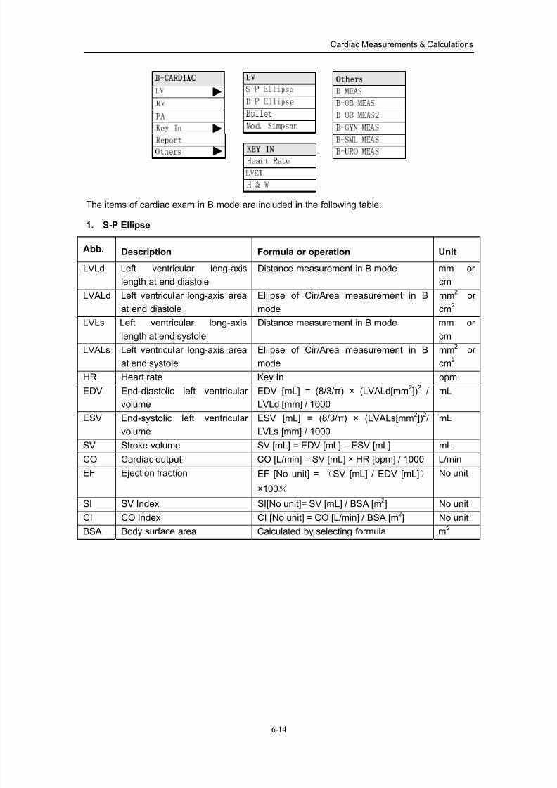
8/11/2019 Mindray DP6600
http://slidepdf.com/reader/full/mindray-dp6600 86/113
Cardiac Measurements & Calculations
6-14
The items of cardiac exam in B mode are included in the following table:
1. S-P Ellipse
Abb. Description Formula or operation Unit
LVLd Left ventricular long-axis
length at end diastole
Distance measurement in B mode mm or
cm
LVALd Left ventricular long-axis area
at end diastole
Ellipse of Cir/Area measurement in B
mode
mm2 or
cm2
LVLs Left ventricular long-axis
length at end systole
Distance measurement in B mode mm or
cm
LVALs Left ventricular long-axis area
at end systole
Ellipse of Cir/Area measurement in B
mode
mm2 or
cm2
HR Heart rate Key In bpm
EDV End-diastolic left ventricular
volume
EDV [mL] = (8/3/π) × (LVALd[mm2])
2 /
LVLd [mm] / 1000
mL
ESV End-systolic left ventricular
volume
ESV [mL] = (8/3/π) × (LVALs[mm2])2/
LVLs [mm] / 1000
mL
SV Stroke volume SV [mL] = EDV [mL] – ESV [mL] mL
CO Cardiac output CO [L/min] = SV [mL] × HR [bpm] / 1000 L/min
EF Ejection fraction EF [No unit] = (SV [mL] / EDV [mL])
×100%
No unit
SI SV Index SI[No unit]= SV [mL] / BSA [m2] No unit
CI CO Index CI [No unit] = CO [L/min] / BSA [m2] No unit
BSA Body surface area Calculated by selecting formula m2
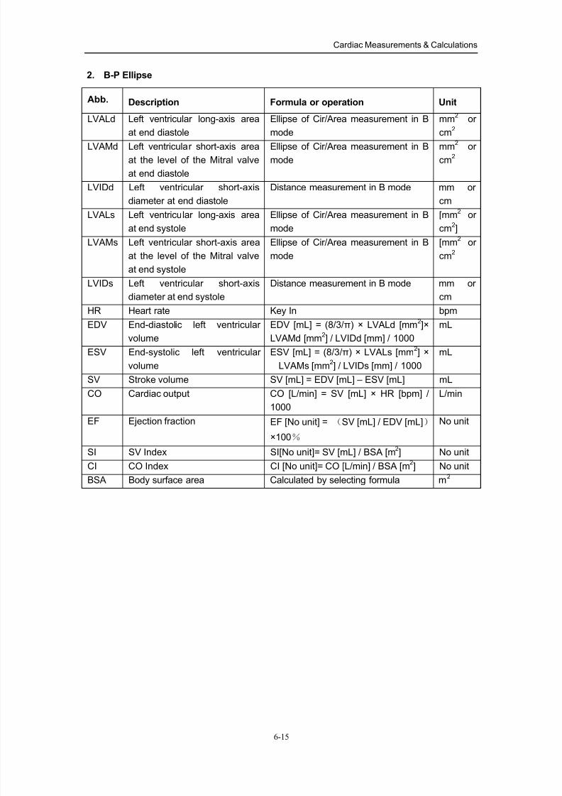
8/11/2019 Mindray DP6600
http://slidepdf.com/reader/full/mindray-dp6600 87/113
Cardiac Measurements & Calculations
6-15
2. B-P Ellipse
Abb. Description Formula or operation Unit
LVALd Left ventricular long-axis area
at end diastole
Ellipse of Cir/Area measurement in B
mode
mm2 or
cm2
LVAMd Left ventricular short-axis area
at the level of the Mitral valve
at end diastole
Ellipse of Cir/Area measurement in B
mode
mm2 or
cm2
LVIDd Left ventricular short-axis
diameter at end diastole
Distance measurement in B mode mm or
cm
LVALs Left ventricular long-axis area
at end systole
Ellipse of Cir/Area measurement in B
mode
[mm2 or
cm2]
LVAMs Left ventricular short-axis area
at the level of the Mitral valve
at end systole
Ellipse of Cir/Area measurement in B
mode
[mm2 or
cm2
LVIDs Left ventricular short-axis
diameter at end systole
Distance measurement in B mode mm or
cm
HR Heart rate Key In bpm
EDV End-diastolic left ventricular
volume
EDV [mL] = (8/3/π) × LVALd [mm2]×
LVAMd [mm2] / LVIDd [mm] / 1000
mL
ESV End-systolic left ventricular
volume
ESV [mL] = (8/3/π) × LVALs [mm2] ×
LVAMs [mm2] / LVIDs [mm] / 1000
mL
SV Stroke volume SV [mL] = EDV [mL] – ESV [mL] mL
CO Cardiac output CO [L/min] = SV [mL] × HR [bpm] /
1000
L/min
EF Ejection fraction EF [No unit] = (SV [mL] / EDV [mL])
×100%
No unit
SI SV Index SI[No unit]= SV [mL] / BSA [m2] No unit
CI CO Index CI [No unit]= CO [L/min] / BSA [m2] No unit
BSA Body surface area Calculated by selecting formula m2
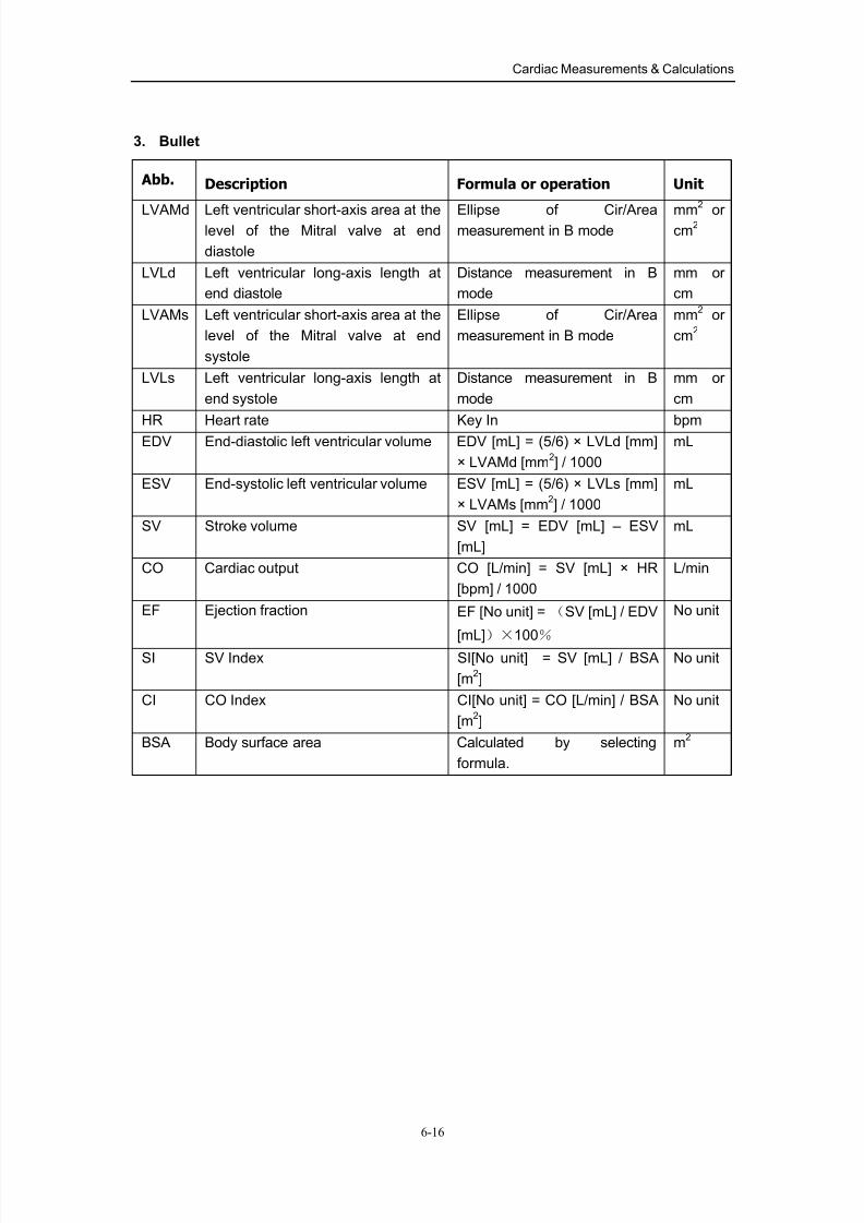
8/11/2019 Mindray DP6600
http://slidepdf.com/reader/full/mindray-dp6600 88/113
Cardiac Measurements & Calculations
6-16
3. Bullet
Abb. Description Formula or operation Unit
LVAMd Left ventricular short-axis area at thelevel of the Mitral valve at end
diastole
Ellipse of Cir/Areameasurement in B mode
mm
2
orcm
2
LVLd Left ventricular long-axis length at
end diastole
Distance measurement in B
mode
mm or
cm
LVAMs Left ventricular short-axis area at the
level of the Mitral valve at end
systole
Ellipse of Cir/Area
measurement in B mode
mm2 or
cm2
LVLs Left ventricular long-axis length at
end systole
Distance measurement in B
mode
mm or
cm
HR Heart rate Key In bpm
EDV End-diastolic left ventricular volume EDV [mL] = (5/6) × LVLd [mm]
× LVAMd [mm2] / 1000
mL
ESV End-systolic left ventricular volume ESV [mL] = (5/6) × LVLs [mm]
× LVAMs [mm2] / 1000
mL
SV Stroke volume SV [mL] = EDV [mL] – ESV
[mL]
mL
CO Cardiac output CO [L/min] = SV [mL] × HR
[bpm] / 1000
L/min
EF Ejection fraction EF [No unit] = (SV [mL] / EDV
[mL])×
100%
No unit
SI SV Index SI[No unit] = SV [mL] / BSA
[m2]
No unit
CI CO Index CI[No unit] = CO [L/min] / BSA
[m2]
No unit
BSA Body surface area Calculated by selecting
formula.
m2
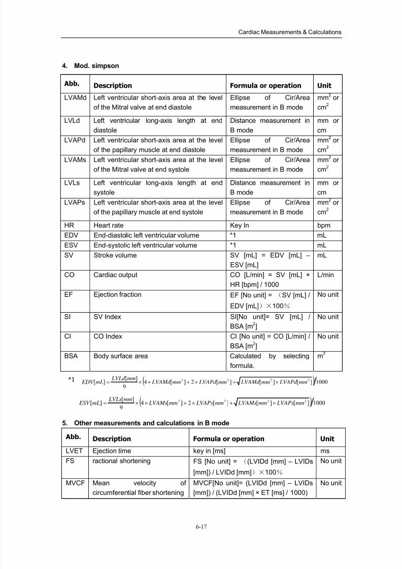
8/11/2019 Mindray DP6600
http://slidepdf.com/reader/full/mindray-dp6600 89/113
Cardiac Measurements & Calculations
6-17
4. Mod. simpson
Abb. Description Formula or operation Unit
LVAMd Left ventricular short-axis area at the levelof the Mitral valve at end diastole
Ellipse of Cir/Areameasurement in B mode
mm
2
orcm
2
LVLd Left ventricular long-axis length at end
diastole
Distance measurement in
B mode
mm or
cm
LVAPd Left ventricular short-axis area at the level
of the papillary muscle at end diastole
Ellipse of Cir/Area
measurement in B mode
mm2 or
cm2
LVAMs Left ventricular short-axis area at the level
of the Mitral valve at end systole
Ellipse of Cir/Area
measurement in B mode
mm2 or
cm2
LVLs Left ventricular long-axis length at end
systole
Distance measurement in
B mode
mm or
cm
LVAPs Left ventricular short-axis area at the level
of the papillary muscle at end systole
Ellipse of Cir/Area
measurement in B mode
mm2 or
cm2
HR Heart rate Key In bpm
EDV End-diastolic left ventricular volume *1 mL
ESV End-systolic left ventricular volume *1 mL
SV Stroke volume SV [mL] = EDV [mL] –
ESV [mL]
mL
CO Cardiac output CO [L/min] = SV [mL] ×
HR [bpm] / 1000
L/min
EF Ejection fraction EF [No unit] = (SV [mL] /
EDV [mL])×100%
No unit
SI SV Index SI[No unit]= SV [mL] /
BSA [m2]
No unit
CI CO Index CI [No unit] = CO [L/min] /
BSA [m2]
No unit
BSA Body surface area Calculated by selecting
formula.
m2
*1 ( ) 1000][][][2][49
][][ 2222
mm LVAPd mm LVAMd mm LVAPd mm LVAMd mm LVLd
mL EDV ×+×+××=
( ) 1000][][][2][49
][][ 2222mm LVAPsmm LVAMsmm LVAPsmm LVAMsmm LVLsmL ESV ×+×+××=
5. Other measurements and calculations in B mode
Abb. Description Formula or operation Unit
LVET Ejection time key in [ms] ms
FS ractional shortening FS [No unit] = ((LVIDd [mm] – LVIDs
[mm]) / LVIDd [mm])×100%
No unit
MVCF Mean velocity of
circumferential fiber shortening
MVCF[No unit]= (LVIDd [mm] – LVIDs
[mm]) / (LVIDd [mm] × ET [ms] / 1000)
No unit
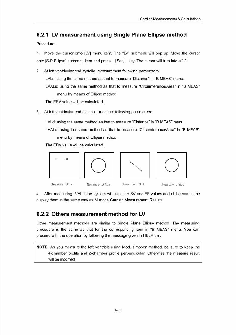
8/11/2019 Mindray DP6600
http://slidepdf.com/reader/full/mindray-dp6600 90/113
Cardiac Measurements & Calculations
6-18
6.2.1 LV measurement using Single Plane Ellipse method
Procedure:
1. Move the cursor onto [LV] menu item. The “LV” submenu will pop up. Move the cursor
onto [S-P Ellipse] submenu item and press 『Set』 key. The cursor will turn into a “+”.
2. At left ventricular end systolic, measurement following parameters:
LVLs: using the same method as that to measure “Distance” in “B MEAS” menu.
LVALs: using the same method as that to measure “Circumference/Area” in “B MEAS”
menu by means of Ellipse method.
The ESV value will be calculated.
3. At left ventricular end diastolic, measure following parameters:
LVLd: using the same method as that to measure “Distance” in “B MEAS” menu.
LVALd: using the same method as that to measure “Circumference/Area” in “B MEAS”
menu by means of Ellipse method.
The EDV value will be calculated.
4. After measuring LVALd, the system will calculate SV and EF values and at the same time
display them in the same way as M mode Cardiac Measurement Results.
6.2.2 Others measurement method for LV
Other measurement methods are similar to Single Plane Ellipse method. The measuring
procedure is the same as that for the corresponding item in “B MEAS” menu. You can
proceed with the operation by following the message given in HELP bar.
NOTE: As you measure the left ventricle using Mod. simpson method, be sure to keep the
4-chamber profile and 2-chamber profile perpendicular. Otherwise the measure result
will be incorrect.

8/11/2019 Mindray DP6600
http://slidepdf.com/reader/full/mindray-dp6600 91/113
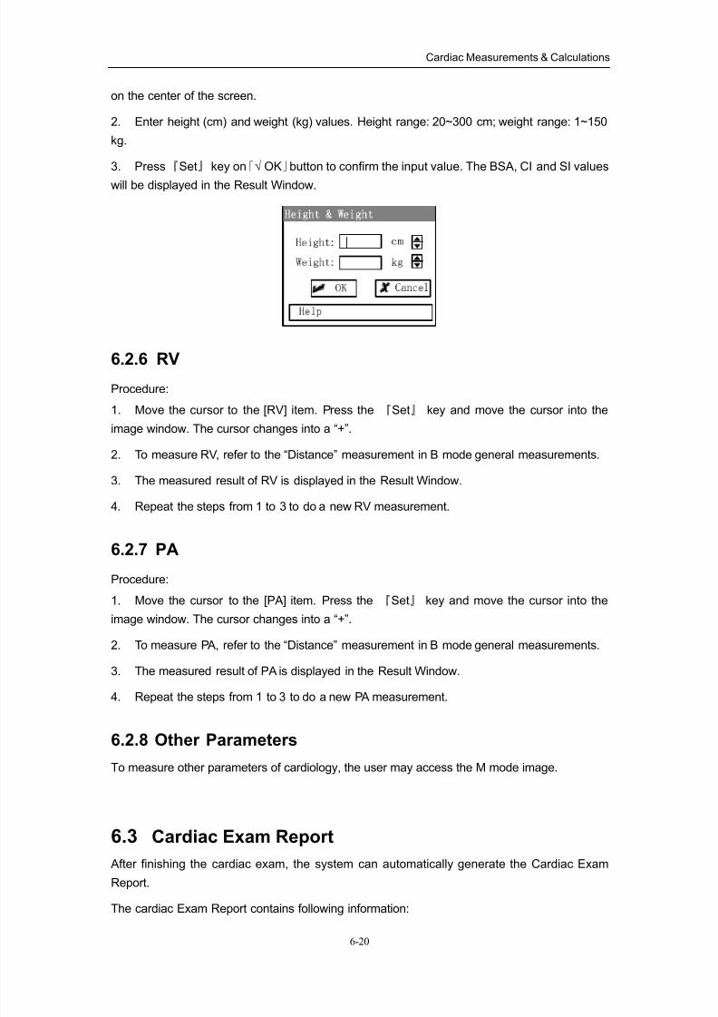
8/11/2019 Mindray DP6600
http://slidepdf.com/reader/full/mindray-dp6600 92/113
Cardiac Measurements & Calculations
6-20
on the center of the screen.
2. Enter height (cm) and weight (kg) values. Height range: 20~300 cm; weight range: 1~150
kg.
3. Press『Set』 key on「√ OK」button to confirm the input value. The BSA, CI and SI values
will be displayed in the Result Window.
6.2.6 RV
Procedure:
1. Move the cursor to the [RV] item. Press the 『Set』 key and move the cursor into the
image window. The cursor changes into a “+”.
2. To measure RV, refer to the “Distance” measurement in B mode general measurements.
3. The measured result of RV is displayed in the Result Window.
4. Repeat the steps from 1 to 3 to do a new RV measurement.
6.2.7 PA
Procedure:
1. Move the cursor to the [PA] item. Press the 『Set』 key and move the cursor into the
image window. The cursor changes into a “+”.
2. To measure PA, refer to the “Distance” measurement in B mode general measurements.
3. The measured result of PA is displayed in the Result Window.
4. Repeat the steps from 1 to 3 to do a new PA measurement.
6.2.8 Other Parameters
To measure other parameters of cardiology, the user may access the M mode image.
6.3 Cardiac Exam Report
After finishing the cardiac exam, the system can automatically generate the Cardiac Exam
Report.
The cardiac Exam Report contains following information:
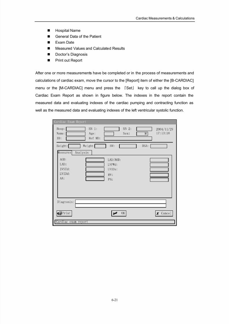
8/11/2019 Mindray DP6600
http://slidepdf.com/reader/full/mindray-dp6600 93/113
Cardiac Measurements & Calculations
6-21
Hospital Name
General Data of the Patient
Exam Date
Measured Values and Calculated Results
Doctor’s Diagnosis
Print out Report
After one or more measurements have be completed or in the process of measurements and
calculations of cardiac exam, move the cursor to the [Report] item of either the [B-CARDIAC]
menu or the [M-CARDIAC] menu and press the 『Set』 key to call up the dialog box of
Cardiac Exam Report as shown in figure below. The indexes in the report contain the
measured data and evaluating indexes of the cardiac pumping and contracting function as
well as the measured data and evaluating indexes of the left ventricular systolic function.
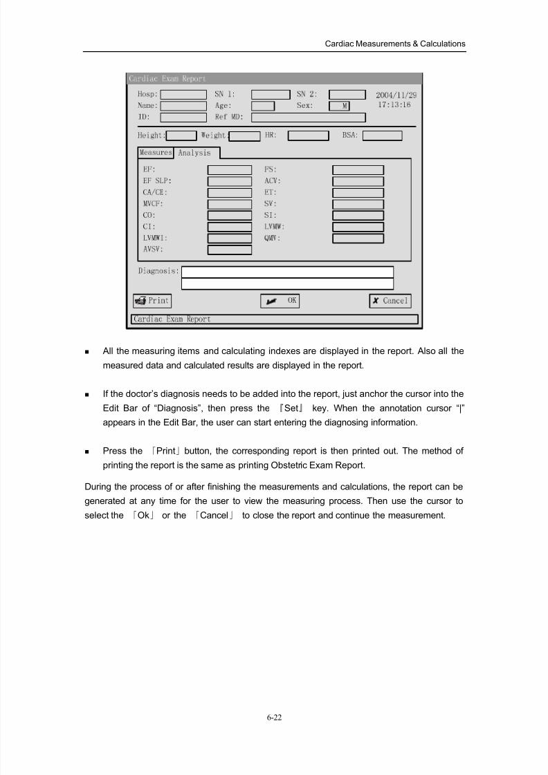
8/11/2019 Mindray DP6600
http://slidepdf.com/reader/full/mindray-dp6600 94/113
Cardiac Measurements & Calculations
6-22
All the measuring items and calculating indexes are displayed in the report. Also all the
measured data and calculated results are displayed in the report.
If the doctor’s diagnosis needs to be added into the report, just anchor the cursor into the
Edit Bar of “Diagnosis”, then press the 『Set』 key. When the annotation cursor “|”
appears in the Edit Bar, the user can start entering the diagnosing information.
Press the 「Print」button, the corresponding report is then printed out. The method of
printing the report is the same as printing Obstetric Exam Report.
During the process of or after finishing the measurements and calculations, the report can be
generated at any time for the user to view the measuring process. Then use the cursor to
select the 「Ok」 or the 「Cancel」 to close the report and continue the measurement.
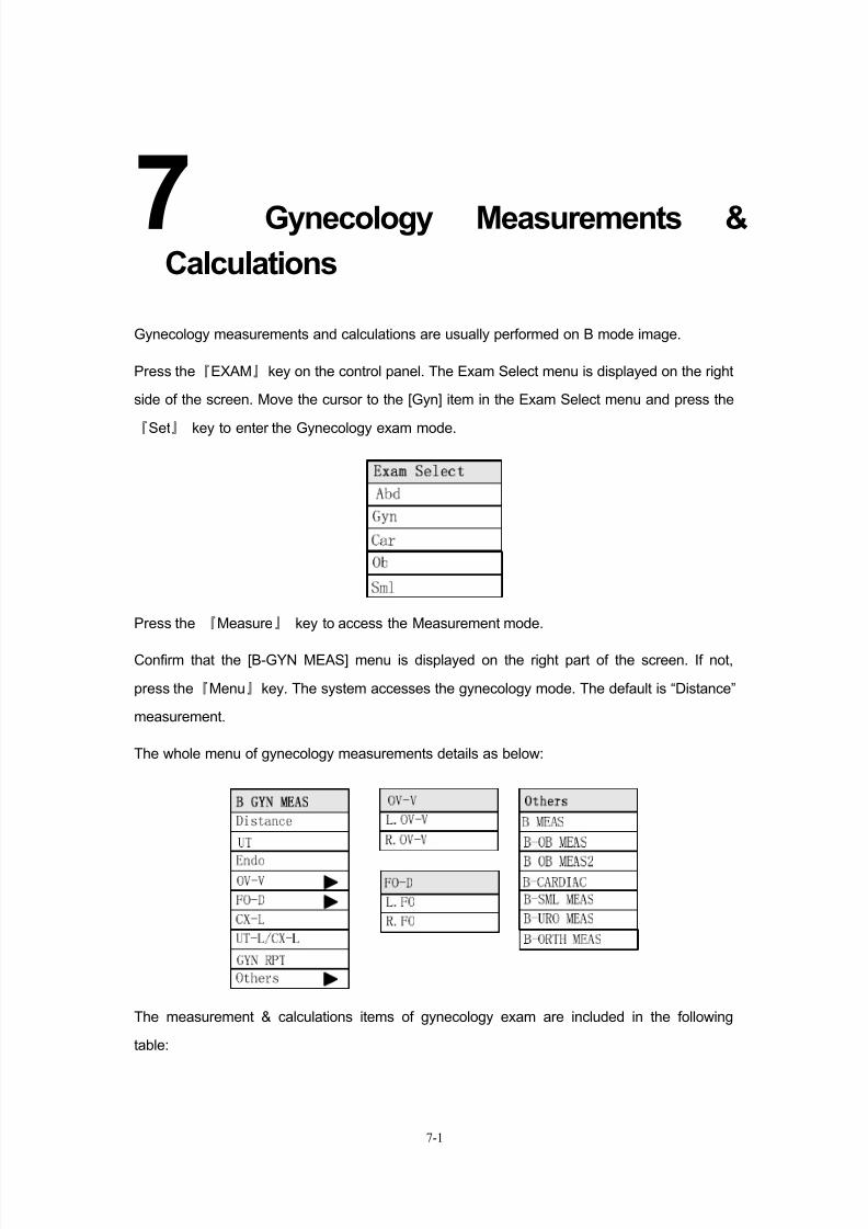
8/11/2019 Mindray DP6600
http://slidepdf.com/reader/full/mindray-dp6600 95/113
7-1
7Gynecology Measurements &
Calculations
Gynecology measurements and calculations are usually performed on B mode image.
Press the『EXAM』key on the control panel. The Exam Select menu is displayed on the right
side of the screen. Move the cursor to the [Gyn] item in the Exam Select menu and press the
『Set』 key to enter the Gynecology exam mode.
Press the 『Measure』 key to access the Measurement mode.
Confirm that the [B-GYN MEAS] menu is displayed on the right part of the screen. If not,
press the『Menu』key. The system accesses the gynecology mode. The default is “Distance”
measurement.
The whole menu of gynecology measurements details as below:
The measurement & calculations items of gynecology exam are included in the following
table:
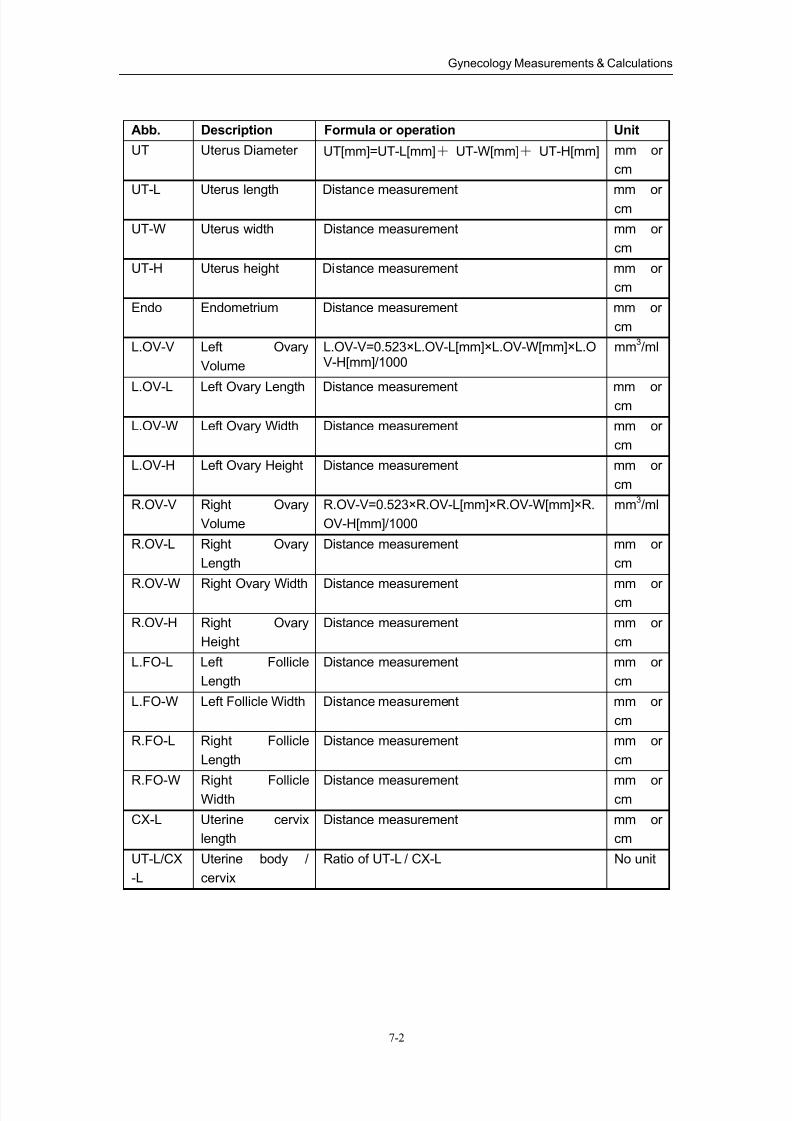
8/11/2019 Mindray DP6600
http://slidepdf.com/reader/full/mindray-dp6600 96/113
Gynecology Measurements & Calculations
7-2
Abb. Description Formula or operation Unit
UT Uterus Diameter UT[mm]=UT-L[mm]+ UT-W[mm]+ UT-H[mm] mm or
cm
UT-L Uterus length Distance measurement mm orcm
UT-W Uterus width Distance measurement mm or
cm
UT-H Uterus height Distance measurement mm or
cm
Endo Endometrium Distance measurement mm or
cm
L.OV-V Left Ovary
Volume
L.OV-V=0.523×L.OV-L[mm]×L.OV-W[mm]×L.OV-H[mm]/1000
mm3/ml
L.OV-L Left Ovary Length Distance measurement mm orcm
L.OV-W Left Ovary Width Distance measurement mm or
cm
L.OV-H Left Ovary Height Distance measurement mm or
cm
R.OV-V Right Ovary
Volume
R.OV-V=0.523×R.OV-L[mm]×R.OV-W[mm]×R.
OV-H[mm]/1000
mm3/ml
R.OV-L Right Ovary
Length
Distance measurement mm or
cm
R.OV-W Right Ovary Width Distance measurement mm orcm
R.OV-H Right Ovary
Height
Distance measurement mm or
cm
L.FO-L Left Follicle
Length
Distance measurement mm or
cm
L.FO-W Left Follicle Width Distance measurement mm or
cm
R.FO-L Right Follicle
Length
Distance measurement mm or
cm
R.FO-W Right FollicleWidth
Distance measurement mm orcm
CX-L Uterine cervix
length
Distance measurement mm or
cm
UT-L/CX
-L
Uterine body /
cervix
Ratio of UT-L / CX-L No unit
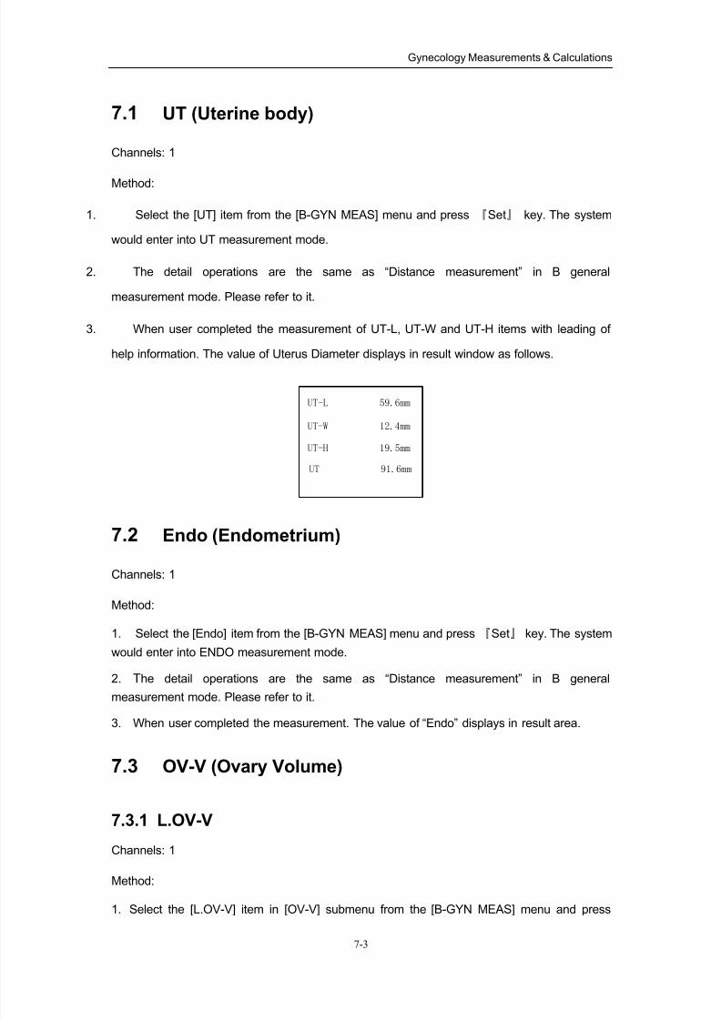
8/11/2019 Mindray DP6600
http://slidepdf.com/reader/full/mindray-dp6600 97/113
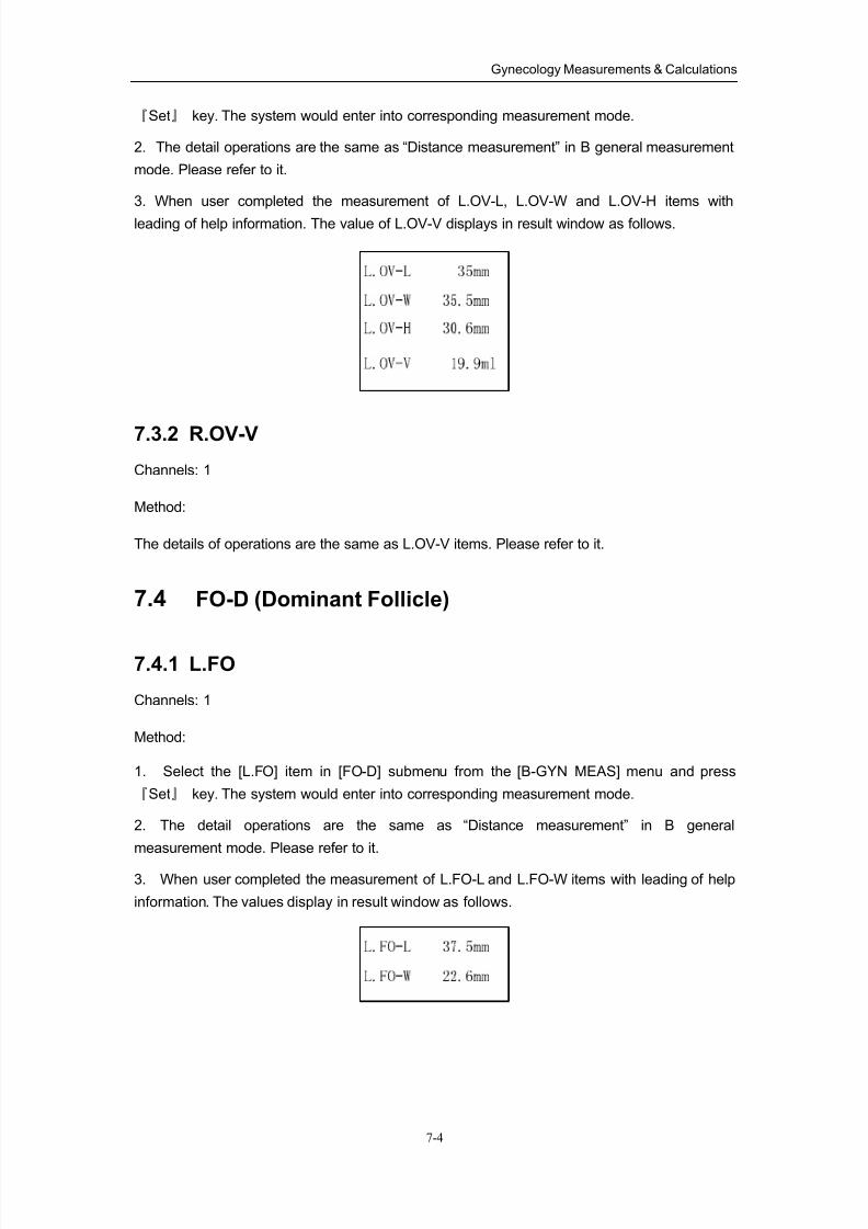
8/11/2019 Mindray DP6600
http://slidepdf.com/reader/full/mindray-dp6600 98/113
Gynecology Measurements & Calculations
7-4
『Set』 key. The system would enter into corresponding measurement mode.
2. The detail operations are the same as “Distance measurement” in B general measurement
mode. Please refer to it.
3. When user completed the measurement of L.OV-L, L.OV-W and L.OV-H items with
leading of help information. The value of L.OV-V displays in result window as follows.
7.3.2 R.OV-V
Channels: 1
Method:
The details of operations are the same as L.OV-V items. Please refer to it.
7.4 FO-D (Dominant Follicle)
7.4.1 L.FO
Channels: 1
Method:
1. Select the [L.FO] item in [FO-D] submenu from the [B-GYN MEAS] menu and press
『Set』 key. The system would enter into corresponding measurement mode.
2. The detail operations are the same as “Distance measurement” in B general
measurement mode. Please refer to it.
3. When user completed the measurement of L.FO-L and L.FO-W items with leading of help
information. The values display in result window as follows.
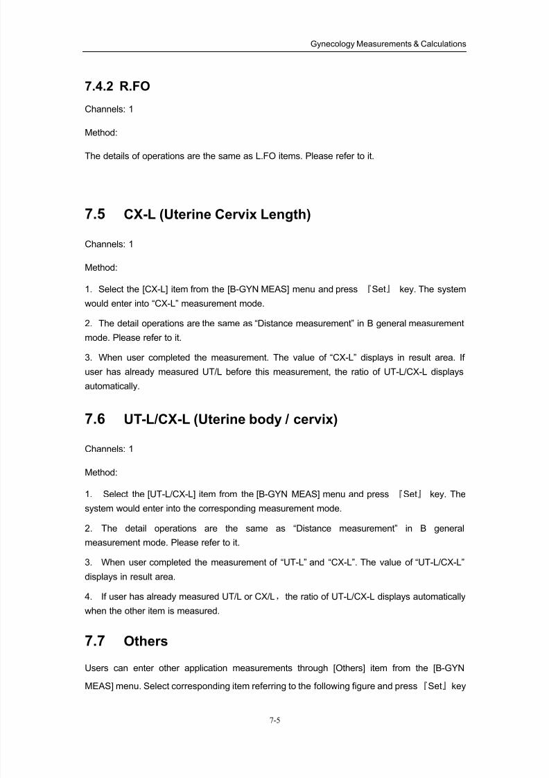
8/11/2019 Mindray DP6600
http://slidepdf.com/reader/full/mindray-dp6600 99/113
Gynecology Measurements & Calculations
7-5
7.4.2 R.FO
Channels: 1
Method:
The details of operations are the same as L.FO items. Please refer to it.
7.5 CX-L (Uterine Cervix Length)
Channels: 1
Method:
1. Select the [CX-L] item from the [B-GYN MEAS] menu and press 『Set』 key. The system
would enter into “CX-L” measurement mode.
2. The detail operations are the same as “Distance measurement” in B general measurement
mode. Please refer to it.
3. When user completed the measurement. The value of “CX-L” displays in result area. If
user has already measured UT/L before this measurement, the ratio of UT-L/CX-L displays
automatically.
7.6 UT-L/CX-L (Uterine body / cervix)
Channels: 1
Method:
1. Select the [UT-L/CX-L] item from the [B-GYN MEAS] menu and press 『Set』 key. The
system would enter into the corresponding measurement mode.
2. The detail operations are the same as “Distance measurement” in B general
measurement mode. Please refer to it.
3. When user completed the measurement of “UT-L” and “CX-L”. The value of “UT-L/CX-L”
displays in result area.
4. If user has already measured UT/L or CX/L,the ratio of UT-L/CX-L displays automatically
when the other item is measured.
7.7 Others
Users can enter other application measurements through [Others] item from the [B-GYN
MEAS] menu. Select corresponding item referring to the following figure and press『Set』key
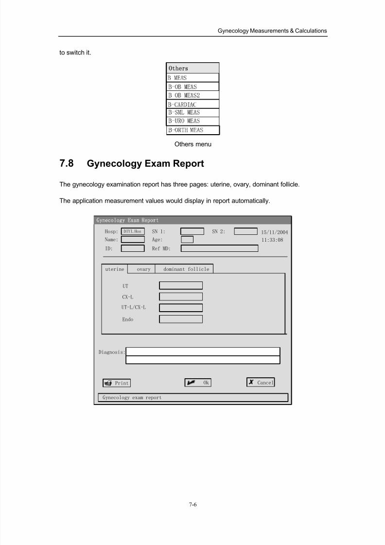
8/11/2019 Mindray DP6600
http://slidepdf.com/reader/full/mindray-dp6600 100/113
Gynecology Measurements & Calculations
7-6
to switch it.
Others menu
7.8 Gynecology Exam Report
The gynecology examination report has three pages: uterine, ovary, dominant follicle.
The application measurement values would display in report automatically.
Ok
Gynecology exam report
Cancel
Hosp:
Name:
SN 1:
Age:
15/11/2004
11:33:08
UT
Diagnosis:
DIYI.Hos
ID:
SN 2:
Ref MD:
uterine ovary dominant follicle
CX-L
UT-L/CX-L
Endo
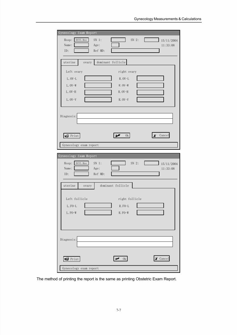
8/11/2019 Mindray DP6600
http://slidepdf.com/reader/full/mindray-dp6600 101/113
Gynecology Measurements & Calculations
7-7
Ok
Gynecology exam report
Cancel
Hosp:
Name:
SN 1:
Age:
15/11/2004
11:33:08
L.OV-L
Diagnosis:
DIYI.Hos
ID:
SN 2:
Ref MD:
uterine ovary dominant follicle
L.OV-W
L.OV-H
L.OV-V
Left ovary
R.OV-L
R.OV-W
R.OV-H
R.OV-V
right ovary
Ok
Gynecology exam report
Cancel
Hosp:
Name:
SN 1:
Age:
15/11/2004
11:33:08
L.FO-L
Diagnosis:
DIYI.Hos
ID:
SN 2:
Ref MD:
uterine ovary dominant follicle
L.FO-W
Left follicle
R.FO-L
R.FO-W
right follicle
The method of printing the report is the same as printing Obstetric Exam Report.
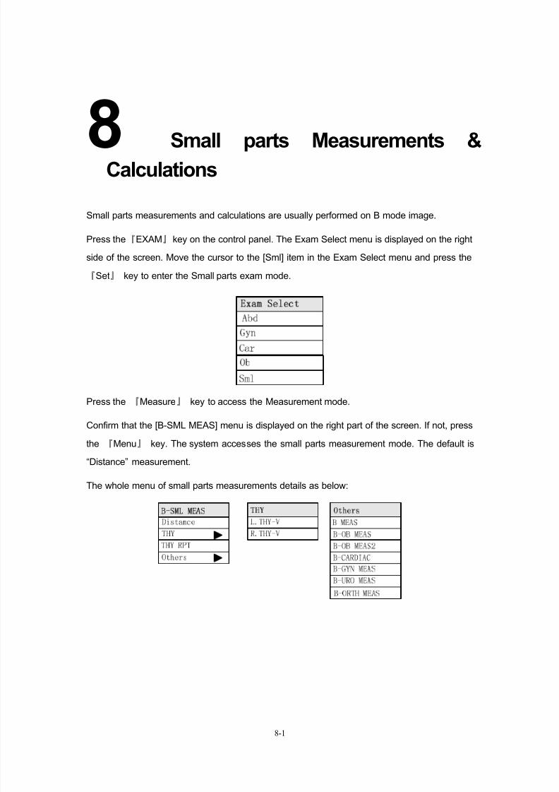
8/11/2019 Mindray DP6600
http://slidepdf.com/reader/full/mindray-dp6600 102/113
8-1
8Small parts Measurements &
Calculations
Small parts measurements and calculations are usually performed on B mode image.
Press the『EXAM』key on the control panel. The Exam Select menu is displayed on the right
side of the screen. Move the cursor to the [Sml] item in the Exam Select menu and press the
『Set』 key to enter the Small parts exam mode.
Press the 『Measure』 key to access the Measurement mode.
Confirm that the [B-SML MEAS] menu is displayed on the right part of the screen. If not, press
the 『Menu』 key. The system accesses the small parts measurement mode. The default is
“Distance” measurement.
The whole menu of small parts measurements details as below:
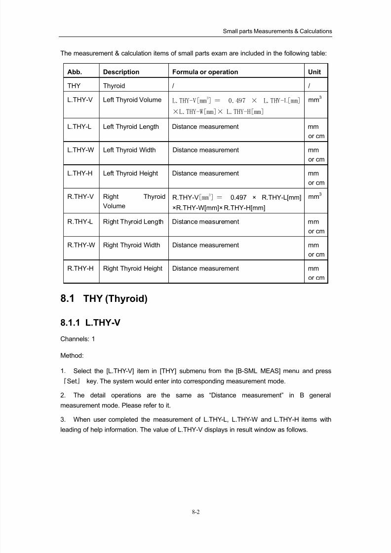
8/11/2019 Mindray DP6600
http://slidepdf.com/reader/full/mindray-dp6600 103/113
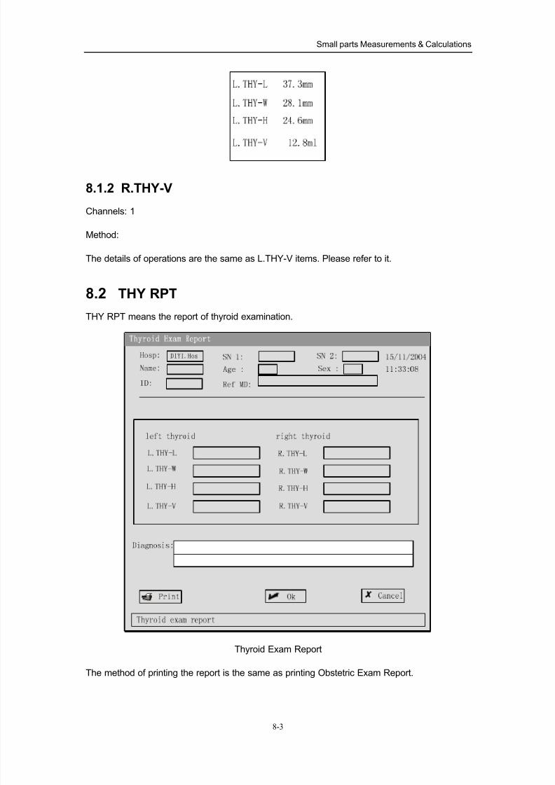
8/11/2019 Mindray DP6600
http://slidepdf.com/reader/full/mindray-dp6600 104/113
Small parts Measurements & Calculations
8-3
8.1.2 R.THY-V
Channels: 1
Method:
The details of operations are the same as L.THY-V items. Please refer to it.
8.2 THY RPT
THY RPT means the report of thyroid examination.
Thyroid Exam Report
The method of printing the report is the same as printing Obstetric Exam Report.
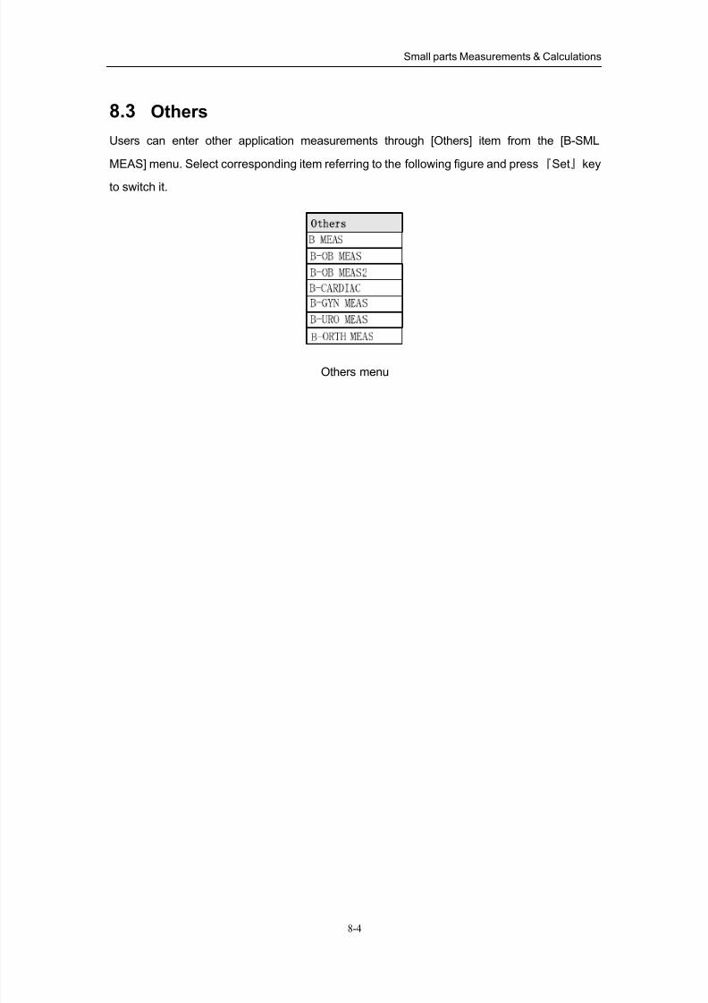
8/11/2019 Mindray DP6600
http://slidepdf.com/reader/full/mindray-dp6600 105/113
Small parts Measurements & Calculations
8-4
8.3 Others
Users can enter other application measurements through [Others] item from the [B-SML
MEAS] menu. Select corresponding item referring to the following figure and press『Set』key
to switch it.
Others menu
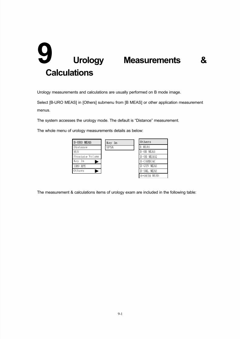
8/11/2019 Mindray DP6600
http://slidepdf.com/reader/full/mindray-dp6600 106/113
9-1
9Urology Measurements &
Calculations
Urology measurements and calculations are usually performed on B mode image.
Select [B-URO MEAS] in [Others] submenu from [B MEAS] or other application measurement
menus.
The system accesses the urology mode. The default is “Distance” measurement.
The whole menu of urology measurements details as below:
The measurement & calculations items of urology exam are included in the following table:
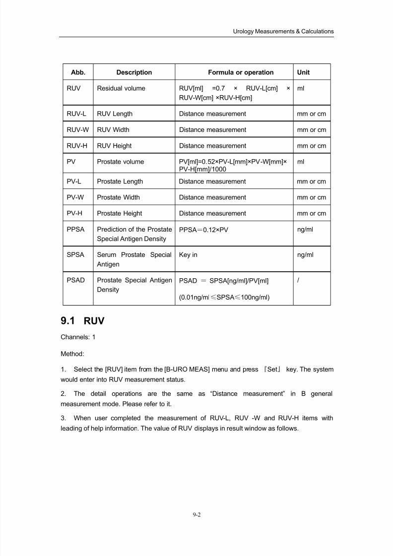
8/11/2019 Mindray DP6600
http://slidepdf.com/reader/full/mindray-dp6600 107/113
Urology Measurements & Calculations
9-2
Abb. Description Formula or operation Unit
RUV Residual volume RUV[ml] =0.7 × RUV-L[cm] ×
RUV-W[cm] ×RUV-H[cm]
ml
RUV-L RUV Length Distance measurement mm or cm
RUV-W RUV Width Distance measurement mm or cm
RUV-H RUV Height Distance measurement mm or cm
PV Prostate volume PV[ml]=0.52×PV-L[mm]×PV-W[mm]×PV-H[mm]/1000
ml
PV-L Prostate Length Distance measurement mm or cm
PV-W Prostate Width Distance measurement mm or cm
PV-H Prostate Height Distance measurement mm or cm
PPSA Prediction of the Prostate
Special Antigen Density
PPSA=0.12×PV ng/ml
SPSA Serum Prostate Special
Antigen
Key in ng/ml
PSAD Prostate Special Antigen
Density
PSAD = SPSA[ng/ml]/PV[ml]
(0.01ng/ml≤SPSA≤100ng/ml)
/
9.1 RUV
Channels: 1
Method:
1. Select the [RUV] item from the [B-URO MEAS] menu and press 『Set』 key. The system
would enter into RUV measurement status.
2. The detail operations are the same as “Distance measurement” in B general
measurement mode. Please refer to it.
3. When user completed the measurement of RUV-L, RUV -W and RUV-H items with
leading of help information. The value of RUV displays in result window as follows.
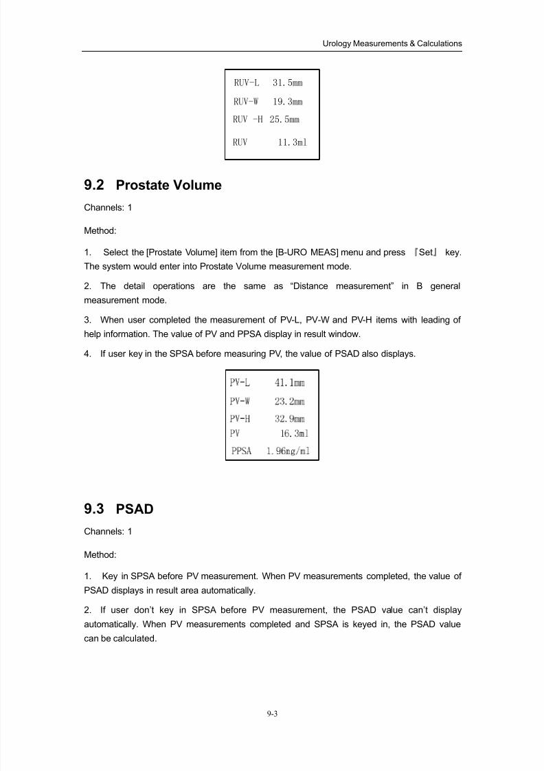
8/11/2019 Mindray DP6600
http://slidepdf.com/reader/full/mindray-dp6600 108/113
Urology Measurements & Calculations
9-3
RUV-L 31.5mm
RUV-W 19.3mm
RUV 11.3ml
RUV -H 25.5mm
9.2 Prostate Volume
Channels: 1
Method:
1. Select the [Prostate Volume] item from the [B-URO MEAS] menu and press 『Set』 key.
The system would enter into Prostate Volume measurement mode.
2. The detail operations are the same as “Distance measurement” in B general
measurement mode.
3. When user completed the measurement of PV-L, PV-W and PV-H items with leading of
help information. The value of PV and PPSA display in result window.
4. If user key in the SPSA before measuring PV, the value of PSAD also displays.
9.3 PSAD
Channels: 1
Method:
1. Key in SPSA before PV measurement. When PV measurements completed, the value of
PSAD displays in result area automatically.
2. If user don’t key in SPSA before PV measurement, the PSAD value can’t display
automatically. When PV measurements completed and SPSA is keyed in, the PSAD value
can be calculated.
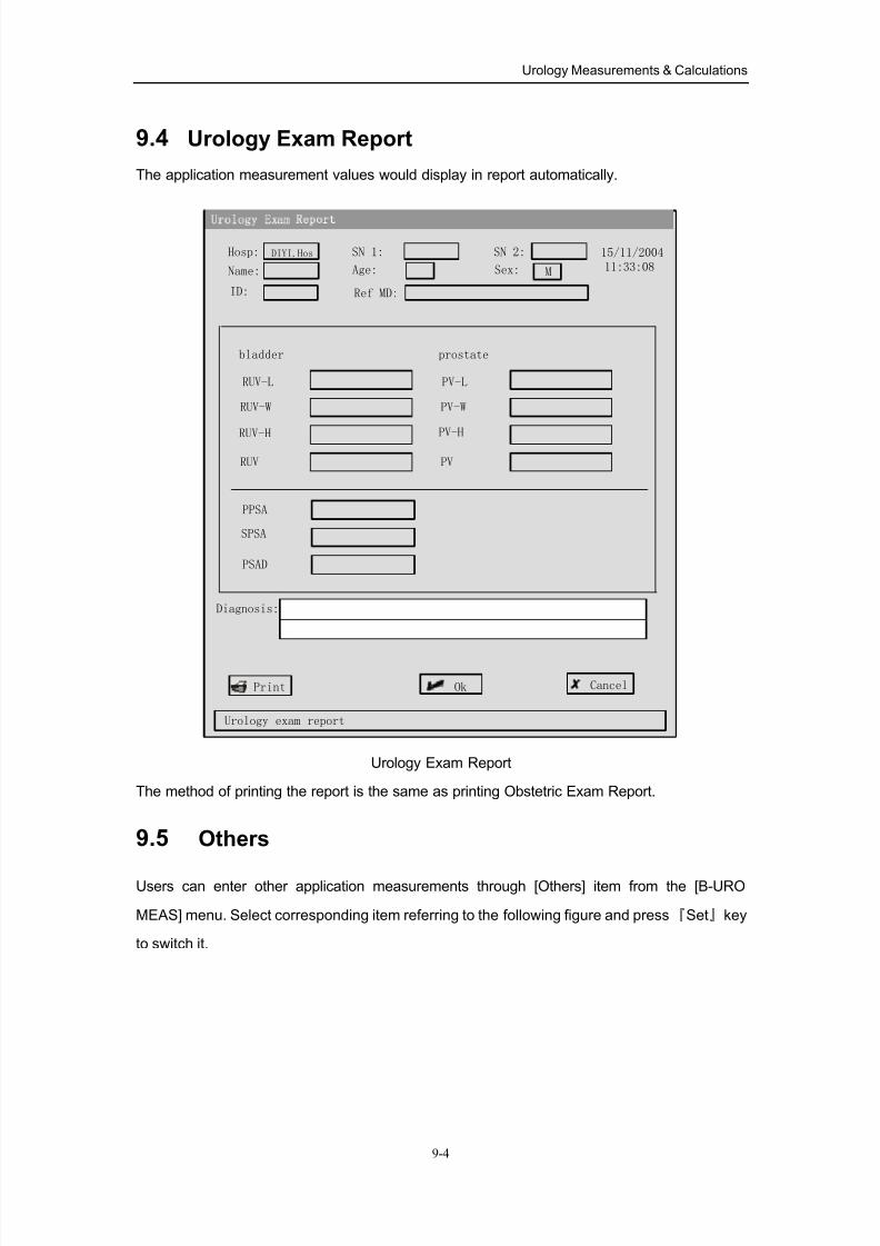
8/11/2019 Mindray DP6600
http://slidepdf.com/reader/full/mindray-dp6600 109/113
Urology Measurements & Calculations
9-4
9.4 Urology Exam Report
The application measurement values would display in report automatically.
Ok
Urology exam report
Cancel
Hosp:
Name:
SN 1:
Age:
15/11/200411:33:08
RUV-L
Diagnosis:
DIYI.Hos
ID:
SN 2:
Ref MD:
RUV-W
RUV-H
RUV
bladder
PV-L
PV-W
PV-H
PV
prostate
PPSA
SPSA
PSAD
MSex:
Urology Exam Report
The method of printing the report is the same as printing Obstetric Exam Report.
9.5 Others
Users can enter other application measurements through [Others] item from the [B-URO
MEAS] menu. Select corresponding item referring to the following figure and press『Set』key
to switch it.
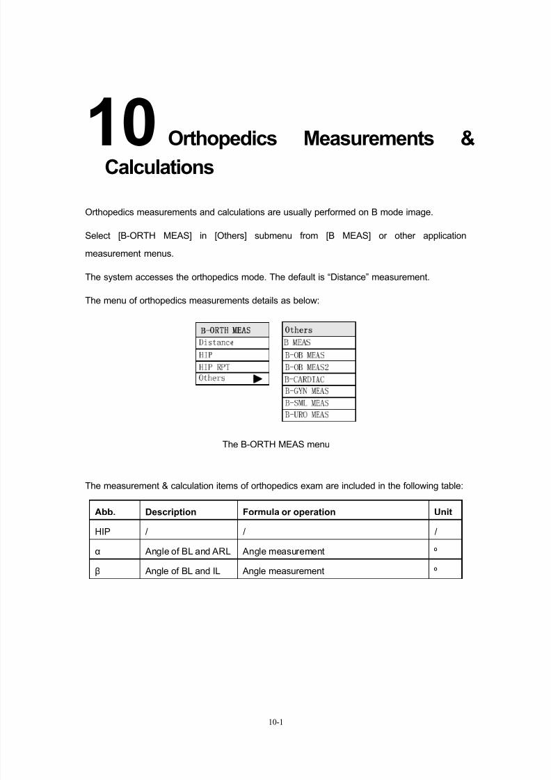
8/11/2019 Mindray DP6600
http://slidepdf.com/reader/full/mindray-dp6600 110/113
10-1
10Orthopedics Measurements &
Calculations
Orthopedics measurements and calculations are usually performed on B mode image.
Select [B-ORTH MEAS] in [Others] submenu from [B MEAS] or other application
measurement menus.
The system accesses the orthopedics mode. The default is “Distance” measurement.
The menu of orthopedics measurements details as below:
The B-ORTH MEAS menu
The measurement & calculation items of orthopedics exam are included in the following table:
Abb. Description Formula or operation Unit
HIP / / /
α Angle of BL and ARL Angle measurement º
β Angle of BL and IL Angle measurement º
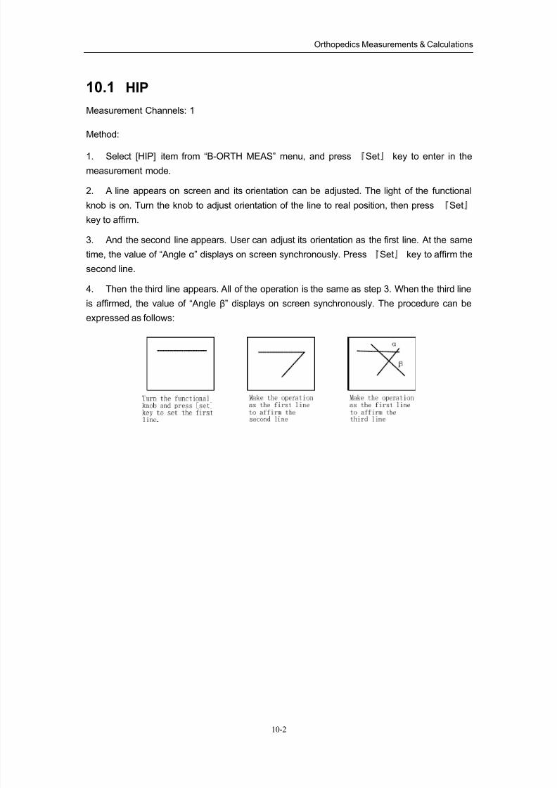
8/11/2019 Mindray DP6600
http://slidepdf.com/reader/full/mindray-dp6600 111/113
Orthopedics Measurements & Calculations
10-2
10.1 HIP
Measurement Channels: 1
Method:
1. Select [HIP] item from “B-ORTH MEAS” menu, and press 『Set』 key to enter in the
measurement mode.
2. A line appears on screen and its orientation can be adjusted. The light of the functional
knob is on. Turn the knob to adjust orientation of the line to real position, then press 『Set』
key to affirm.
3. And the second line appears. User can adjust its orientation as the first line. At the same
time, the value of “Angle α” displays on screen synchronously. Press 『Set』 key to affirm the
second line.
4. Then the third line appears. All of the operation is the same as step 3. When the third line
is affirmed, the value of “Angle β” displays on screen synchronously. The procedure can be
expressed as follows:
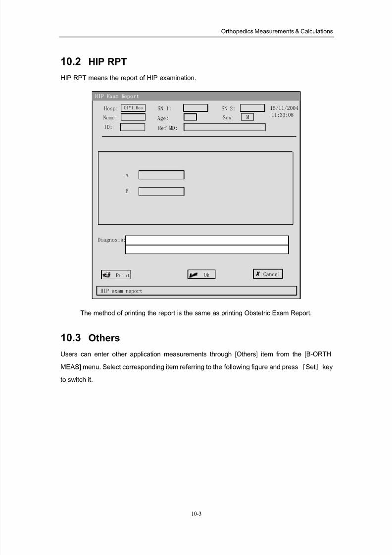
8/11/2019 Mindray DP6600
http://slidepdf.com/reader/full/mindray-dp6600 112/113
Orthopedics Measurements & Calculations
10-3
10.2 HIP RPT
HIP RPT means the report of HIP examination.
Ok
HIP exam report
Cancel
Hosp:
Name:
SN 1:
Age:
15/11/2004
11:33:08
Diagnosis:
DIYI.Hos
ID:
SN 2:
Ref MD:
a
ß
MSex:
The method of printing the report is the same as printing Obstetric Exam Report.
10.3 Others
Users can enter other application measurements through [Others] item from the [B-ORTH
MEAS] menu. Select corresponding item referring to the following figure and press『Set』key
to switch it.

8/11/2019 Mindray DP6600
http://slidepdf.com/reader/full/mindray-dp6600 113/113


