GUIDELINE For the Compilation of a Mandatory Code of Practice for the Design, Development/Construction, Safe Operation and Maintenance of Draw Points, Tipping Points, Rock Passes and Box Fronts MINE HEALTH AND SAFETY INSPECTORATE
Transcript
GUIDELINE
For the Compilation of a Mandatory Code of Practice for the Design,Development/Construction, Safe Operation and Maintenance of DrawPoints, Tipping Points, Rock Passes and Box Fronts
MINE HEALTH AND SAFETY INSPECTORATE
GUIDELINE
For the Compilation of a Mandatory Code of Practice for the Design,Development/Construction, Safe Operation and Maintenance of Draw
Points, Tipping Points, Rock Passes and Box Fronts
MINE HEALTH AND SAFETY INSPECTORATE
Chief Inspector of Mines
Date
31 January 2011
For the Compilation of a Mandatory Code of Practice for the Design,Development/Construction, Safe Operation and Maintenance of Draw Points,
Tipping Points, Rock Passes and Box Fronts
Published by:DEPARTMENT OF MINERAL RESOURCESPrivate Bag x59Arcadia0007
Tel: +27 12 444 3000
Website: www.dmr.gov.za
ISNB 1-919927-47-6
For the Compilation of a Mandatory Code of Practice for the Design,Development/Construction, Safe Operation and Maintenance of Draw Points,
Tipping Points, Rock Passes and Box Fronts
CONTENTS OF GUIDELINE
1. FOREWORD2. LEGAL STATUS OF GUIDELINES AND CODES OF PRACTICE3. THE OBJECTIVE OF THIS GUIDELINE4. DEFINITION5. SCOPE6. MEMBERSHIP OF TASK GROUP PREPARING THE GUIDELINE
1. TITLE PAGE2. TABLE OF CONTENTS3. STATUS OF CODE OF PRACTICE4. MEMBERS OF DRAFTING COMMITTEE5. GENERAL INFORMATION6. TERMS AND DEFINITIONS7. RISK MANAGEMENT8. ASPECTS TO BE ADDRESSED IN THE MANDATORY CODE OF PRACTICE
8.1 Draw points8.1.1 Design
8.1.4 Operations8.1.5 Maintenance
8.2.1 Design8.2.2 Slipping8.2.3 Construction and Installation8.2.4 Operations
8.3.1 Design8.3.2 Development / Excavating8.3.3 Construction and Installation8.3.4 Operations
8.4.1 Design8.4.2 Construction, Installation and Removal8.4.3 Operations8.4.4 Maintenance
1. IMPLEMENTATION PLAN2. COMPLIANCE WITH THE CODE OF PRACTICE3. ACCESS TO THE CODE OF PRACTICE AND RELATED DOCUMENTS
ANNEXURE “A”: REFERENCESANNEXURE “B1” MAINTENANCE EXAMINATION CHECK LISTANNEXURE “B2” FITTER’S CHUTE CONTROL MAINTENANCE CHECK LIST
PART A: THE GUIDELINE
PART B: AUTHOR’S GUIDE
PART C: FORMAT AND CONTENT OF THE CODE OF PRACTICE
PART D: IMPLEMENTATION
8.2 Tipping points
8.3 Rock Passes
8.4 Box fronts
1
111123
3
4
4444555566666777788899999
101111111111
12
121212
132728
8.2.5 Maintenance
8.1.2 Development and Excavating8.1.3 Construction and Installation
8.3.5 Maintenance
For the Compilation of a Mandatory Code of Practice for the Design,Development/Construction, Safe Operation and Maintenance of Draw Points,
Tipping Points, Rock Passes and Box Fronts
PART A: THE GUIDELINE
1. FOREWORD
This guideline affects mines at which draw points, tipping points, rock passes and box fronts areused for the transport and transferring of rock.
Draw points, tipping points, rock passes and box fronts have been identified by the Chief Inspector ofMines as an area requiring legislation. A task group was established under the auspices of the MineRegulations Advisory Committee to investigate the most appropriate means of legislation for thistopic. After considering it was decided that the use of a guideline for a COP would be the mostappropriate means of legislation for draw points, tipping points, rock passes and box fronts as it willallow for mine specific safety measures to be written into a comprehensive mine health and safetystrategy.
2. LEGAL STATUS OF GUIDELINES AND COPS
3. THE OBJECTIVE OF THIS GUIDELINE
The objective of this guideline is to enable the employer at every mine to compile a COP, which, ifproperly implemented and complied with, would improve health and safety in connection with thedesign, development, construction, operation and maintenance of draw points, tipping points, rockpasses and box fronts at a mine.
4. DEFINITIONS
In this guideline for a COP or any amendment thereof the following abbreviations are used:
4.1 Arching means the natural process by which fractured rock acquires a certain amount ofability to support itself through the resolution of the vertical component of its weight intodiagonal thrust.
4.2 Blockage means an obstruction of the flow of rock in a rock pass.
4.3 Box front means a structure installed at lower opening of a rock pass to control the flow ofrock that includes the bulkheads, chutes, platforms, control mechanisms, cylinders and similaraccessories.
4.4 Bridging means formation of arches of keyed or jammed rocks across the direction of flow.
4.5 Chute means an inclined trough through which rock falls by gravity from a higher to a lowerlevel.
4.6 Competent person1 means a person with Government Certificate of Competency(mechanical or electrical) or equivalent competency as may be determined by MQA.
2.1 In accordance with section 9(2) of the MHSA an employer must prepare and implement a COP onany matter affecting the health and safety of employees and other persons who may be directlyaffected by activities at the mine if the Chief Inspector of Mines requires it. These COPs mustcomply with any relevant guidelines issued by the Chief Inspector of Mines (section 9(3)) of theMHSA. Failure by the employer to prepare or implement a COP in compliance with this guideline isbreach of the MHSA.
1
For the Compilation of a Mandatory Code of Practice for the Design,Development/Construction, Safe Operation and Maintenance of Draw Points,
Tipping Points, Rock Passes and Box Fronts
4.7 COP means Code of Practice
4.8 Dead boxes means an excavation in a rock pass that fills with rock where the flow of rockimpacts and the direction of the flow of rock is changed.
4.9 Development means a tunnelling operation.
4.10 DMR means Department of Mineral Resources
4.11 Dog legs means an abrupt change of direction of a rock pass.
4.12 Draw point means a point where the rock is loaded out or allowed to flow out from anexcavation.
4.13 Grizzly means a structure at the top entrance of a rock pass to control the size of the rocksentering into the rock pass which consist of grizzly bars supported by a designed foundation.
4.14 Hang-up means broken rock lodged in a rock pass forming a blockage.
4.15 MHSA means Mine Health and Safety Act, 1996, (Act 29 of 1996).
4.16 Mud rush means a sudden uncontrolled outflow of mud, water or wet material from drawpoints, chutes, box fronts or any other underground workings.
4.17 Professional Engineer means an engineer registered with the Engineering Council of SouthAfrica.
4.18 Professional Technologist means a technologist registered with the Engineering Council ofSouth Africa.
4.19 Rock means for the purpose of this document rock includes: ore, waste rock, coal or anyother minerals.
4.20 Rock pass means steeply inclined excavation used to transport and store rock betweenworking places and transfer points.
4.21 Rock pass leg means a straight portion of a rock pass.
4.22 SANS means South African National Standard
4.23 Tipping point means the upper inlet into the rock pass.
5. SCOPE
This guideline covers the significant health and safety aspects associated with the design,development, excavation, installation, construction, operation and maintenance of draw points,tipping points, rock passes and box fronts.
2
For the Compilation of a Mandatory Code of Practice for the Design,Development/Construction, Safe Operation and Maintenance of Draw Points,
Tipping Points, Rock Passes and Box Fronts
6. TASK GROUP MEMBERSHIP
6.1 This guideline was prepared by the MRAC Tripartite Task Group on draw points, tipping points, rockpasses and box fronts.
6.2 The members appointed were the following:
Mr W A Masztalerz ChairpersonMr W J M Welding StateMr P du Preez StateMr I Stocks StateMr J Taylor Employers
The following persons were consulted:
Mr C Hey Amplats Dr K Wainwright Amplats
Prof T R Stacey University of Witwatersrand
PART B: AUTHORS’ GUIDE
1. The COP must, where possible, follow the sequence laid out in Part C “Format and Content of themandatory COP”. The pages as well as the chapters and sections must be numbered to facilitatecross-reference. Wording must be unambiguous and concise.
2. It should be indicated in the COP and on each annex to the COP whether-
(a) the annex forms part of the guideline and must be complied with or incorporated in the COPor whether aspects thereof must be complied with or incorporated in the COP, or
(b) the annex is merely attached as information for consideration in the preparation of the COP(i.e. compliance is discretionary).
3. When annexes are used the letter allocated to that particular annex should precede the numberingand the numbering should start at one (1) again. (eg. 1, 2, 3, …A1, A2, A3,…).
4. Whenever possible illustrations, tables, graphs and the like, should be used to avoid longdescriptions and/or explanations.
5. When reference has been made in the text to publications or reports, references to these sourcesmust be included in the text as footnotes or sidenotes as well as in a separate bibliography
3
For the Compilation of a Mandatory Code of Practice for the Design,Development/Construction, Safe Operation and Maintenance of Draw Points,
Tipping Points, Rock Passes and Box Fronts
PART C: FORMAT AND CONTENT OF THE MANDATORY CODE OF PRACTICE.
1. TITLE PAGE
The title page must include the following:
• name of the mine;• the Heading: “Mandatory COP for the safe design, development, construction,
operation and maintenance of draw points, tipping points, rock passes and box fronts forthe transport and transfer of rock”;
• a statement to the effect that the COP was drawn up in accordance with this guideline• (quoting the reference number and revision date) issued by the Chief Inspector of Mines;• the mine’s reference number for the COP;• effective date, and• revision dates.
2. TABLE OF CONTENTS
The COP must have a comprehensive table of contents.
3. STATUS OF MANDATORY CODE OF PRACTICE
This section must contain statements to the effect that:
3.1 The mandatory COP was drawn up in accordance with Guideline DMR 16/3/2/2-A6 issued by theChief Inspector of Mines.
3.2 This is a mandatory COP in terms of Sections 9(2) and (3) of the Mine Health and Safety Act.
3.3 The COP may be used in an incident investigation/inquiry to ascertain compliance and also toestablish whether the COP is effective and fit for purpose.
3.4 The COP supersedes all previous relevant Codes of Practice.
3.5 All managerial instructions or recommended procedures (Voluntary COP) and standards on therelevant topics must comply with the COP and must be reviewed to assure compliance.
4. MEMBERS OF DRAFTING COMMITTEE
4.1 In terms of Section 9(4) of the MHSA the employer must consult with the health and safetycommittee on the preparation, implementation or revision of any COP.
4.2 It is recommended that the employer should, after consultation with the employees in terms of theMHSA, appoint a committee responsible for the drafting of the COP.
4.3 The members of the drafting committee assisting the employer in drafting the COP should be listedgiving their full names, designations, affiliations and experience. This committee should includecompetent persons sufficient in number to effectively draft the COP.
4
For the Compilation of a Mandatory Code of Practice for the Design,Development/Construction, Safe Operation and Maintenance of Draw Points,
Tipping Points, Rock Passes and Box Fronts
5. GENERAL INFORMATION
The general information relating to the mine must be stated in this paragraph. The following minimum information must be provided:
5.1 a brief description of the mine and its location;5.2 the commodities produced;5.3 the mining methods/mineral excavation processes;5.4 a description of the draw points, tipping points, rock passes and box fronts systems used in or on the
mine (including relevant information such as the application and technical specifications), and5.5 other relevant Codes of Practice.
6. TERMS AND DEFINITIONS
Any term, definition or acronym of which the meaning is not absolutely clear must be clearly defined.
7. RISK MANAGEMENT
7.1 Section 11 of the MHSA requires the employer to identify hazards, assess the health and safetyrisks to which employees may be exposed while they are at work, and record the significant hazardsidentified and risk assessed. The COP must address how the significant risks identified in the riskassessment process must be dealt with, having regard to the requirements of Section 11(2) and (3)that, as far as reasonably practicable, attempts should first be made to eliminate the risk, thereafterto control the risk at source, thereafter to minimise the risk and thereafter, insofar as the riskremains, provide personal protective equipment and to institute a program to monitor the risk.(Annexure “A1”)
7.2 To assist the employer with risk assessment all possible relevant information such as incidentstatistics, studies, research reports, manufacturers specifications, international standards, designcriteria and performance figures for the draw points, tipping points, rock passes and box frontsshould be obtained and considered.
7.3 In addition to the periodic review required by Section 11(4) of the Act, the COP should be reviewedand updated after every serious incident involving the draw points, tipping points, rock passes andbox fronts or if significant changes are introduced to procedures, mining and ventilation layouts,mining methods, plant or equipment and material.
8. ASPECTS TO BE ADDRESSED IN THE MANDATORY CODE OF PRACTICE
The COP must set out how the significant risks assessed and identified in terms of the risk assessmentprocess referred to in paragraph 7.1, will be addressed unless there is no significant risk associated with thataspect at the mine, the COP must cover at least the aspects set out below. (Annexure “A1”)
5
For the Compilation of a Mandatory Code of Practice for the Design,Development/Construction, Safe Operation and Maintenance of Draw Points,
Tipping Points, Rock Passes and Box Fronts
8.1 DRAWPOINT
8.1.1 DRAWPOINT DESIGN
In order to ensure that a defensible design is produced, which provides for a safe operation and a healthy workingenvironment, the COP must set out a description of the design strategy to be adopted by covering, at least, thefollowing -
• A clear statement of the problem that requires design, including the expected performanceobjectives.
• Identification of all constraints that might impose certain requirements on the design.• The collection and analysis of all necessary data that is required for the design.• The competency of the person responsible for the design process• The evaluation of alternative designs including a risk assessment of all designs.• The definition and recommendation of all necessary monitoring devices.
8.1.2 DRAWPOINT DEVELOPMENT
In order to ensure ground stability of the drawpoint and its associated tunnels and to provide for a safe operationand a healthy working environment, the COP must set out a description of the development strategy to be adoptedby covering, at least, the following –
• The correct design of drilling patterns and accuracy of drill holes• The type of explosives and initiating systems to be used and the sequence of initiation• The design and type of primary support required to maintain the integrity of the excavations.
8.1.3 DRAWPOINT CONSTRUCTION AND INSTALLATION
In order to provide for a safe operation and a healthy working environment, the COP must set out adescription of the construction and installation strategy to be adopted by covering, at least, the following –
• Drawpoint construction and installation processes, methodology, techniques andsequences.
• The support requirements for drawpoints in different rocks and in different miningenvironments. Reference must be made to the relevant geotechnical environment and tothe mining process and equipment to be used in that environment.
• The competency of the person responsible for the construction and installation processes.• The competency of the person supervising the construction and installation processes.• The competencies and skill levels of the relevant crews.• The quality of work performed and it’s compliance to approved design (refer to paragraph
8.1.1).
8.1.4 DRAWPOINT OPERATIONS
In order to prevent persons from being injured during daily operations and to provide for a safe operation and ahealthy working environment, the COP must set out a description of the operations strategy to be adopted bycovering, at least, the following –
• Drawpoint operational processes, methodology, techniques and sequences.
• Measures employed to monitor areas of potential ground movement.• Measures employed to monitor and protect the integrity of all access and escape ways.
6
For the Compilation of a Mandatory Code of Practice for the Design,Development/Construction, Safe Operation and Maintenance of Draw Points,
Tipping Points, Rock Passes and Box Fronts
• Measures employed to monitor orebody depletion on a continuous basis so as to avoidpotential incidents such as air blasts and mud rushes.
• The competencies and skill levels of the relevant crews.
8.1.5 DRAWPOINT MAINTENANCE
In order to provide for a safe operation and a healthy working environment, the COP must set out adescription of the maintenance strategy to be adopted by covering, at least, the following –
• Drawpoint maintenance processes, methodology, techniques and sequences• The competency of the person responsible for the maintenance process.• The competency of the person supervising the maintenance process.• The competencies and skill levels of the relevant crews.• The quality of work performed and it’s compliance to approved design (refer to paragraph
8.1.1).• Measures employed to monitor drawpoint deterioration and repair scheduling
Annex “A2” is appended for information and reference purposes only for the design, development,construction, installation, operation and maintenance of drawpoints.
8.2 TIPPING POINTS
8.2.1 TIPPING POINT DESIGN
In order to ensure that a defensible design is produced, which provides for a safe operation and a healthyworking environment, the COP must set out a description of the design strategy to be adopted by covering,at least, the following -
• A clear statement of the problem that requires design, including the expected performanceobjectives.
• Identification of all constraints that might impose certain requirements on the design.• The collection and analysis of all necessary data that is required for the design.• The competency of the person responsible for the design process• The evaluation of alternative designs including a risk assessment of all designs.• The definition and recommendation of all necessary monitoring devices.
8.2.2 TIPPING POINT SLIPING
In order to ensure ground stability of the tipping point and it’s associated tunnels and to provide for a safe operationand a healthy working environment, the COP must set out a description of the blasting / excavating strategy to beadopted by covering, at least, the following –
• Breaking method• Maximum and minimum size of excavation• The design and type of support required to maintain the integrity of the excavations.
7
For the Compilation of a Mandatory Code of Practice for the Design,Development/Construction, Safe Operation and Maintenance of Draw Points,
Tipping Points, Rock Passes and Box Fronts
8.2.3 TIPPING POINT CONSTRUCTION AND INSTALLATION
In order to provide for a safe operation and a healthy working environment, the COP must set out a description ofthe construction and installation strategy to be adopted by covering, at least, the following –
• Tipping point construction and installation processes, methodology, techniques andsequences.
• The support requirements for tipping points in different rocks and in different miningenvironments. Reference must be made to the relevant geotechnical environment and tothe mining process and equipment to be used in that environment.
• The competency of the person responsible for the construction and installation processes.• The competency of the person(s) supervising the construction and installation processes.• The competencies and skill levels of the relevant crews.• The quality of work performed and it’s compliance to approved design (refer to paragraph
8.2.1).
8.2.4 TIPPING POINT OPERATIONS
In order to prevent persons from being injured during daily operations and to provide for a safe operation and ahealthy working environment, the COP must set out a description of the operations strategy to be adopted bycovering, at least, the following –
• Tipping point operational processes, methodology, techniques and sequences.• Measures employed to monitor areas of potential ground movement.• Measures employed to monitor and protect the integrity of all access and escape ways.• Measures employed to monitor quantity of rock handled and to prevent the cross tramming
of ore to waste and vice versa• The competencies and skill levels of the relevant crews.
8.2.5 TIPPING POINT MAINTENANCE
In order to provide for a safe operation and a healthy working environment, the COP must set out a description ofthe maintenance strategy to be adopted by covering, at least, the following –
• Tipping point maintenance processes, methodology, techniques and sequences• The competency of the person responsible for the maintenance process.• The competency of the person supervising the maintenance process.• The competencies and skill levels of the relevant crews.• The quality of work performed and it’s compliance to approved design (refer to paragraph
8.2.1).• Measures employed to monitor tipping point deterioration and the repair schedule.
Annexure “A2” is for information and reference purposes only for the design, development, construction,installation, operation and maintenance of tipping points.
8
For the Compilation of a Mandatory Code of Practice for the Design,Development/Construction, Safe Operation and Maintenance of Draw Points,
Tipping Points, Rock Passes and Box Fronts
8.3 ROCK PASSES
8.3.1 ROCK PASS DESIGN
In order to ensure that a defensible design is produced, which provides for a safe operation and a healthy workingenvironment, the COP must set out a description of the design strategy to be adopted by covering, at least, thefollowing-
• A clear statement of the problem that requires design, including the expected performance objectives• Identification of all constraints that might impose certain requirements on the design• The collection and analysis of all necessary data (including but not limited to dimensions, capacities,
geological structure, rock properties) that is required for the design.• The competency of the person responsible for the design process• The evaluation of alternative designs including a risk assessment of all designs.• The definition and recommendation of all necessary monitoring devices.
8.3.2 ROCK PASS DEVELOPMENT/ EXCAVATING
In order to ensure ground stability of the rock pass and its associated tunnels and to provide for a safe operationand a healthy working environment, the COP must set out a description of the development strategy to be adoptedby covering, at least, the following -
• The correct design of drilling patterns and accuracy of drill holes• The type of explosives and initiating systems to be used and the sequence of initiation• The design and type of primary support required to maintain the integrity of excavations.
8.3.3 ROCK PASS CONSTRUCTION AND INSTALLATION
In order to provide for a safe operation and a healthy working environment, the COP must set out a descriptionof the construction and installation strategy to be adopted by covering, at least, the following -
• Rock pass construction and installation processes, methodology, techniques and sequences.• The support requirements for rock pass in different rocks and in different mining environments.• Reference must be made to the relevant geotechnical environment and to the mining process and
equipment to be used in that environment.• The competency of the person responsible for the construction and installation processes.• The competency of the person supervising the construction and installation processes.• The competencies and skill levels of the relevant crews.• The quality of work performed and its compliance to approved design (refer to paragraph 8.3.1 )
8.3.4 ROCK PASS OPERATIONS
In order to prevent persons from being injured during daily operations and to provide for a safe operation anda healthy working environment, the COP must set out a description of the operations strategy to be adopted bycovering, at least, the following -
• Rock pass operational processes, methodology, techniques and sequences• Measures employed to monitor areas of potential ground movement.• Measures employed to monitor and protect the integrity of all access and escape ways• Measures employed to monitor ore body depletion on a continuous basis so as to avoid potential
incidents such as air blasts and mud rushes.• The competencies and skill levels of the relevant crews
9
For the Compilation of a Mandatory Code of Practice for the Design,Development/Construction, Safe Operation and Maintenance of Draw Points,
Tipping Points, Rock Passes and Box Fronts
8.3.5 ROCK PASS MAINTENANCE
In order to provide safe operation and healthy working environment, the COP must set out a description of themaintenance strategy to be adopted by covering, at least, the following -
• Rock pass maintenance processes, methodology, techniques and sequences.• The competency of the person responsible for the maintenance process.• The competency of the person supervising the maintenance process.• The competency and skill levels of the relevant crews• The quality of work performed and its compliance to approved design (refer to paragraph 8.3.1)• Measures employed to monitor rock pass deterioration and repair scheduling.
Annex “A4” is appended for information and reference purposes only for the design, development, construction,installation, operation and maintenance of rock pass.
10
For the Compilation of a Mandatory Code of Practice for the Design,Development/Construction, Safe Operation and Maintenance of Draw Points,
Tipping Points, Rock Passes and Box Fronts
8.4.1 BOX FRONT DESIGN
In order to ensure that a defensible design is produced, which provides for a safe operation and a healthyworking environment, the COP must set out a description of the design strategy to be adopted by covering,at least, the following -
• A clear statement of the problem that requires design, including the expected performanceobjectives.
• Identification of all constraints that might impose certain requirements on the design.• The collection and analysis of all necessary data (including, but not limited to dimensions,
capacities, geological structure, rock properties) that is required for the design.• The competency of the person responsible for the design process• The evaluation of alternative designs including a risk assessment of all designs.• The definition and recommendation of all necessary monitoring devices.
8.4.2 BOX FRONT CONSTRUCTION, INSTALLATION AND REMOVAL
In order to provide for a safe operation and a healthy working environment, the COP must set out adescription of the construction, installation and removal procedure to be adopted by covering, at least, thefollowing –
• Box front construction and installation processes, methodology, techniques andsequences.
• The support requirements for box front in different rocks and in different miningenvironments.
• The competency of the person responsible for the construction, installation and removalprocesses.
• The competency of the person(s) supervising the construction, installation and removalprocesses.
• The competencies and skill levels of the relevant crews.• The quality of work performed and it’s compliance to approved design (refer to paragraph
8.4.1).
8.4.3 BOX FRONT OPERATIONS
In order to prevent persons from being injured during daily operations and to provide for a safe operation anda healthy working environment, the COP must set out a description of the operations strategy to be adoptedby covering, at least, the following –
• Box front operational processes, methodology, techniques and sequences.• Measures employed to monitor areas of potential ground movement.• Measures employed to monitor and protect the integrity of all access and escape ways.• The competencies and skill levels of the relevant crews.
8.4.4 BOX FRONTS MAINTENANCE
In order to provide for a safe operation and a healthy working environment, the COP must set out adescription of the maintenance strategy to be adopted by covering, at least, the following –
• Box front maintenance processes, methodology, techniques and sequences.• The competency of the person responsible for the maintenance process.• The competency of the person supervising the maintenance process.• The competencies and skill levels of the relevant crews.
8.4 BOX FRONTS
11
For the Compilation of a Mandatory Code of Practice for the Design,Development/Construction, Safe Operation and Maintenance of Draw Points,
Tipping Points, Rock Passes and Box Fronts
• The quality of work performed and its compliance to approved design (refer to paragraph8.4.1).
• Measures employed to monitor box front deterioration and repair schedule.
Annex “A3” is appended for information and reference purposes only for the design, development,construction, installation, operation and maintenance of box fronts.
PART D: IMPLEMENTATION
1. IMPLEMENTATION PLAN
1.1 The employer must prepare an implementation plan for its COP that makes provision for issues suchas organisational structures, responsibilities of functionaries and programs and schedules for thisCOP that will enable proper implementation of the COP. (A summary of/and a reference to, acomprehensive implementation plan may be included).
1.2 Information may be graphically represented to facilitate easy interpretation of the data and tohighlight trends for the purpose of risk assessment.
2. COMPLIANCE WITH THE CODE OF PRACTICE
The employer must institute measures for monitoring and ensuring compliance with the COP.
3. ACCESS TO THE CODE OF PRACTICE AND RELATED DOCUMENTS
3.1 The employer must ensure that a complete COP and related documents are kept readily available atthe mine for examination by any affected person.
3.2 A registered trade union with members at the mine or where is no such union, a health and safetyrepresentative on the mine, or if there is no health and safety representative, an employeerepresenting the employees on the mine, must be provided with a copy on written request to themanager. A register must be kept of such persons or institutions with copies to facilitate updating ofsuch copies.
3.3 The employer must ensure that all employees are fully conversant with those sections of the COPrelevant to their respective areas of responsibility.
ANNEXURES
Annexures, or references within the annexes, are marked (A) or (B) according to whether,
(a) it forms part of the guideline and must be complied with or incorporated in the COP or whether aspects thereof must be complied with or incorporated in the COP, or
(b) it is merely attached as information for consideration in the preparation of the COP (i.e. compliance is discretionary).
12
For the Compilation of a Mandatory Code of Practice for the Design,Development/Construction, Safe Operation and Maintenance of Draw Points,
Tipping Points, Rock Passes and Box Fronts
ANNEXURE “A”
REFERENCES
1 Simrac Report – OTH 3032 SANS 10208 Part IV
13
For the Compilation of a Mandatory Code of Practice for the Design,Development/Construction, Safe Operation and Maintenance of Draw Points,
Tipping Points, Rock Passes and Box Fronts
ANNEXURE “A1”
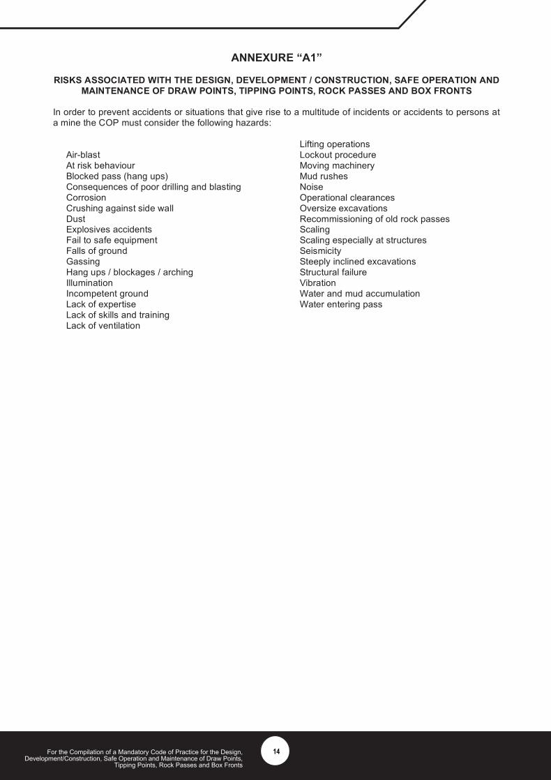
RISKS ASSOCIATED WITH THE DESIGN, DEVELOPMENT / CONSTRUCTION, SAFE OPERATION ANDMAINTENANCE OF DRAW POINTS, TIPPING POINTS, ROCK PASSES AND BOX FRONTS
In order to prevent accidents or situations that give rise to a multitude of incidents or accidents to persons ata mine the COP must consider the following hazards:
Air-blastAt risk behaviourBlocked pass (hang ups)Consequences of poor drilling and blastingCorrosionCrushing against side wallDustExplosives accidentsFail to safe equipmentFalls of groundGassingHang ups / blockages / archingIlluminationIncompetent groundLack of expertiseLack of skills and trainingLack of ventilation
Lifting operationsLockout procedureMoving machineryMud rushesNoiseOperational clearancesOversize excavationsRecommissioning of old rock passesScalingScaling especially at structuresSeismicitySteeply inclined excavationsStructural failureVibrationWater and mud accumulationWater entering pass
14
For the Compilation of a Mandatory Code of Practice for the Design,Development/Construction, Safe Operation and Maintenance of Draw Points,
Tipping Points, Rock Passes and Box Fronts
ANNEXURE “A2”
THE DESIGN, DEVELOPMENT, CONSTRUCTION, SAFE OPERATION AND MAINTENANCE OFDRAWPOINTS
1. DRAWPOINT DESIGN
The design and planning of drawpoints should consider the following aspects:
1.1 Geotechnical studies
A geotechnical study of the orebody should be carried out to collect data that will allow for rock massclassification in accordance with one of the commonly recognised rock mass classification systems. Datathat should be collected includes uniaxial compressive strength of the rocks, joint spacing, joint conditionand stress levels. Important design and planning parameters, in particular fragmentation, miningsequence, support design caveability and caving radius, should be derived from this study.
1.2 Numerical modeling
Numerical modeling is a useful design and planning tool and should be considered as it defines areas ofpotential high stresses (and possible failures) that may / will impact on designed mining layout and miningsequences. The parameters needed for stress modeling must be derived from the geotechnicalevaluation and rock mass classification.
1.3 Ellipsoid of draw
The draw ellipsoid of a particular fragmented rock will have a significant impact on drawpoint design.Drawpoint size and spacings will be affected by the interaction between adjacent draw ellipsoids.
1.4 Drawpoint spacings
The size of a drawpoint is a function of rock mass strength and the support requirements. The height ofa drawpoint is a function of rock mass strength and will determine the rill distance from the brow.
2. DRAWPOINT DEVELOPMENT AND EXCAVATION
The development of the drawpoint and its associate crosscut is important for the optimal operation of themining block. Therefore, cognizance should be taken of properly designed and detailed developmentrounds and the drilling thereof. This is necessary to ensure that;
• The bullnose and camelback are not damaged during development.• The drawpoint brow area is not damaged and that the required support can be installed.• The distances across the major apices are developed according to design.• Overbreak is minimized with minimal effect on support quality.
3. DRAWPOINT CONSTRUCTION AND INSTALLATION
Drawpoint construction is essentially a support operation and needs to be done in accordance with theoperation’s procedures. This should clearly specify the support requirements for drawpoints in differentrock types and different mining environments.
Drawpoint installation is a skilled operation and should be done in accordance with a procedure approvedby the mine, which includes details of, but not limited to, the skills level requirements of the installationcrew, approved engineering drawings (refer to paragraph 8.1.1) and quality control.
15
For the Compilation of a Mandatory Code of Practice for the Design,Development/Construction, Safe Operation and Maintenance of Draw Points,
Tipping Points, Rock Passes and Box Fronts
4. OPERATIONS AND TRAINING
The risks associated with massive mining need to be understood by those persons involved with suchoperations. As a result drawpoint operations should be governed by approved procedures that addressthe:
4.1 Mining sequence
A system should be developed on mine that ensures that the designed mining sequence is adhered to, inparticular the relationships between drawpoint development, drawpoint installation, trough opening andundercut face position.
4.2 Draw control
A draw control system and strategy should be developed prior to any ore production through thedrawpoints. This strategy should address issues such as draw rate, trough opening, waste ingress androck state.
4.3 Secondary drilling and blasting
A secondary drilling and blasting system should be readily available so that hang-ups – be they high orlow – can be blasted and cleared. Lack of availability of drawpoints can impact on the draw control planand production targets. Procedures and risk assessments should cover drilling, charging and blastingvarious types of hang-ups as well as the operation of the associated vehicles and equipment.
4.4 Drawpoint rehabilitation
Mining operations and mining induced stress changes impact on the strength of the rock causingdeterioration, in particular drawpoint brows and bull noses.
4.5 Cave monitoring
Cave monitoring (and cave back propagation) should be undertaken continuously to avoid incidents suchas air blasts and mud rushes. The continuous monitoring will provide early warning on potential cavingproblems that could impact on safety and production.
4.6 Training
Laid down procedures including risk assessments should be developed to train all relevant personnel whoundertake loading, secondary drilling and blasting and rehabilitation work.
16
For the Compilation of a Mandatory Code of Practice for the Design,Development/Construction, Safe Operation and Maintenance of Draw Points,
Tipping Points, Rock Passes and Box Fronts
ANNEXURE “A3”
THE DESIGN, DEVELOPMENT, CONSTRUCTION, SAFE OPERATION AND MAINTENANCE OFTIPPING POINTS
1. TIPPING POINT DESIGN
The design and planning of tipping points should consider the following aspects:
1.1 Geotechnical studies
A geotechnical study of the orebody should be carried out to collect data that will allow for rock massclassification in accordance with one of the commonly recognised rock mass classification systems. Datathat should be collected includes uniaxial compressive strength of the rocks, joint spacing, joint conditionand stress levels. Important design and planning parameters, in particular fragmentation, miningsequence, support design caveability and caving radius, should be derived from this study.
1.2 Numerical modeling
Numerical modeling is a useful design and planning tool and should be considered as it defines areas ofpotential high stresses (and possible failures) that may / will impact on designed mining layout and miningsequences. The parameters needed for stress modeling must be derived from the geotechnicalevaluation and rock mass classification.
1.3 Dynamics of operation
The shock forces of hoppers being tipped or scrapers delivering rock should be considered. Secondarybreaking of rock needs to be considered to take into account blasting vibrations.
1.4 Grizzly bar opening size
Openings of grizzly bars are a function of the system capability to handle the maximum size rocks fromthis point through the mine’s transport system as well as the oversized fraction likely to occur and thesecondary breaking techniques.
2. TIPPING POINT DEVELOPMENT AND EXCAVATION
The development of the tipping point and its associate filter chamber is important for the optimal operationof the mining block. Therefore, cognisance should be taken of properly designed and detaileddevelopment rounds and the drilling thereof. This is necessary to ensure that;
• The bullnose and camelback are not damaged during development.• The distances across the major apices are developed according to design.• Overbreak is minimized with minimal effect on support quality.
3. TIPPING POINT CONSTRUCTION AND INSTALLATION
Tipping point construction is essentially a support operation and needs to be done in accordance with theoperation’s procedures. This should clearly specify the support requirements for tipping points in differentrock types and different mining environments.
Tipping point installation is a skilled operation and should be done in accordance with a procedureapproved by the mine, which includes details of, but not limited to, the skills level requirements of theinstallation crew, approved engineering drawings (refer to paragraph 8.2.1) and quality control.
17
For the Compilation of a Mandatory Code of Practice for the Design,Development/Construction, Safe Operation and Maintenance of Draw Points,
Tipping Points, Rock Passes and Box Fronts
4. OPERATIONS AND TRAINING
The risks associated with massive mining need to be understood by persons involved with suchoperations. Further, tipping point operations should be governed by procedures that address at least thefollowing;
4.1 Mining sequence
A system should be developed on mine that ensures that the designed mining sequence is adhered to, inparticular the relationships between tipping point development, tipping point installation, trough openingand undercut face position.
4.1 Draw control
A draw control system and strategy should be developed prior to any ore production through the tippingpoints. This strategy should address issues such as draw rate, air blast, waste ingress and rock state.
4.2 Secondary drilling and blasting
A secondary drilling and blasting system should be readily available so that hang-ups – be they high orlow – can be blasted and cleared. Lack of availability of tipping points can impact on the draw controlplan and production targets. Procedures and risk assessments should cover drilling, charging andblasting various types of hang-ups as well as the operation of the associated vehicles and equipment.
4.3 Tipping point rehabilitation
Mining operations and mining induced stress changes impact on the strength of the rock causingdeterioration, in particular tipping point brows and bull noses.
4.4 Draw monitoring
Draw monitoring should be conduct continuously to avoid incidents such as; air blasts and mud rushes.The continuously monitoring will provide early warning on potential blockages, arching, bridging etc.problems that could impact on safety and production.
4.5 Training
Laid down procedures including risk assessments should be developed to train all relevant personnel whoundertake loading, secondary drilling and blasting and rehabilitation work.
18
For the Compilation of a Mandatory Code of Practice for the Design,Development/Construction, Safe Operation and Maintenance of Draw Points,
Tipping Points, Rock Passes and Box Fronts
ANNEXURE “A4”
THE DESIGN, DEVELOPMENT, CONSTRUCTION, SAFE OPERATION AND MAINTENANCE OF ROCKPASSES
1. Design
The design of rock passes should include specific consideration of the following aspects:
1.1 Location of passes
Locations of passes should be chosen to avoid poor rock if possible. If this is not possible, lining may benecessary.
1.2 Orientation of passes with respect to geological structure
Rock failure in passes occurs more readily for some orientations with respect to the geological structure thanfor others. In stratified rock masses, passes should be oriented to intersect the strata as near toperpendicular as possible.
1.3 Orientation of passes with respect to stress
In high stress conditions, the best pass orientation with respect to the stresses is sub-parallel to themaximum principal stress. If other factors allow, this orientation should be used if it is suitable.
1.4 Size of pass
The risk of hang-ups due to rock arching is a function of the size of the pass with respect to the size of therock blocks being passed. If the material being passed contains more than 20% fines, the risk of cohesivearching is present. A recommended pass size is at least 5 times the size of the largest rock fragment beingpassed.
1.5 Inclination of pass
The effects of pass inclination are summarized in the following Table. The minimum recommendedinclination is 55 º, which is applicable for dry ore, which flows well. In general, pass inclination should begreater that 60º, and even steeper if wet fines are present.
Velocity of rock Higher. Rocks bouncing againstwalls can cause damage
Lower
Impact High. Can cause compaction Low. Impact for vertical passescan be about 4 x that for 50ºpasses
Wear Lower. Only impact damage dueto velocity
Higher due to sliding of material onfootwall
length Shorter Longer for the same verticalinterval
Hang-ups Less likely. High compaction mainadverse effect
More likely. Slower movement ofore, accumulation of material(particularly ‘sticky’), greaterlength, are main adverse effects.
1.6 Length of passes
The longer the pass, the more likely it is to have problems, owing to the greater extent of rock masstraversed, the greater velocities that material can attain, and, the greater difficult of access to clear a hang –up of blockage and when rehabilitation is required.
19
For the Compilation of a Mandatory Code of Practice for the Design,Development/Construction, Safe Operation and Maintenance of Draw Points,
Tipping Points, Rock Passes and Box Fronts
1.7 Method of excavation
The comparative effects of boring and drill and blast excavation are given in the following Table. Rougheningof bored passes reduces velocities and increases the pass size. Blasted passes tend to be larger than boredpasses for the same requirement.
Slower – greater possibility ofaccumulation of material
Hang-ups Less likely for the same pass size.Compaction is an adverseinfluence
More likely for the same size
1.8 Control of water in passes
Water entering passes from whatever source is adverse, since formation of ‘”sticky” rock is likely, the risk ofhang-ups and mud rushes is increases, and, the flow of rock is affected. Uncontrolled inflow of water shouldtherefore be prevented.
1.9 Pass system geometry
The geometries of dog legs, bends and branch intersections are important, since they are locations subjectto wear, impact and slowing of material flow. A small included angle results in greater impact, greaterpotential for accumulation of material, and greater slowing of rock flow and such bends are therefore morelikely locations for hang-ups. Experience suggests that included angles of >120º should be used. Sizes ofbranches and main passes must ensure that constriction does not occur.
1.10 Methods of support of passes
Support is not usually installed in passes. However, the risk of deterioration of passes, hang-ups andblockages may be reduced by implementing support – rock reinforcement, shotcrete, concrete or steel lining– or a combination of these measures. Rock support will require specific design considerations. ‘Support’and steel items in particular are ‘foreign material’ which, when worn and loosened, can be the cause of hang-ups.
2. Development / excavating
In order to prevent accidents or situations that give rise to a multitude of incidents or accidents to persons ata mine the COP must consider the following hazards:
• Explosive accidents• Incompetent ground• Oversize excavations• Steeply inclined excavations• Lack of ventilation• Lack of skills and training• At risk behaviour
These hazards and associated risks can be eliminated or mitigated by appropriate development andexcavating procedures and must be addressed in the COP.
20
For the Compilation of a Mandatory Code of Practice for the Design,Development/Construction, Safe Operation and Maintenance of Draw Points,
Tipping Points, Rock Passes and Box Fronts
3. Operation / Training
In order to prevent accidents or situations that give rise to a multitude of incidents or accidents topersons at a mine the COP must consider the following hazards:
• Mud rushes• Consequences of poor drilling and blasting• Explosive accidents• Crushing against side wall• Water entering pass• Oversize excavations• Blocked pass ( hang ups)• Scaling especially at structures• Lack of ventilation• Lack of skills and training• At risk behaviour
These hazards and associated risks can be eliminated or mitigated by appropriate operation and trainingprocedures as dealt with below and must be addressed in the COP.
3.1 Controlled and uncontrolled pass operationAdvantages and disadvantages of controlled and uncontrolled passes are summarized in the Tablebelow. To minimize the risk of hang-ups, material should be drawn to keep the rock column moving.This is particularly important if water is present. This will prevent the consolidation of the material inthe pass as far as possible.
CONTROLLED PASSES UNCONTROLLED PASSES
Advantages Confinement by rock material inpass promotes pass stability.Reduced impact wear. Reducedscaling. Reduced effect ofseismicity. Collapses minimized.Impact compaction reduced.
Reduced risk of block arch hang-ups.
Reduced risk of sticky ore hang-ups.
Access from top down if necessary
Disadvantages Hang-up risk due to block archingincreased.
Hang-up risk due to sticky orecompaction increased
Reduced stability since noconfinement of pass walls.Scaling and collapse riskincreased.Impact wear.Impact compaction increased.Potential damage to box frontsand chutes.
3.2 Methods of clearing hang-ups and blockagesIf a hang-up has been located, the alternative ways in which it can be cleared must be carefully considered.In clearing hang-ups using explosives, it is the concussion that is usually relief on to loosen the hang-ups.The use of explosives may damage the walls of the pass, which can produce geometry changes orroughness that can be the nuclei for further hang-ups. The use of water to clear hang-ups in passes can bedangerous since it may lead to mud rushes, and must therefore be carefully controlled.
4. Maintenance/Training
In order to prevent accidents or situations that give rise to a multitude of incidents or accidents to persons ata mine the COP must consider the following hazards:
• Incompetent ground• Steeply inclined excavations• Blocked pass (hang-ups)• Scaling especially at structures• Lack of ventilation• Lack of skills and training• At risk behaviour
21
For the Compilation of a Mandatory Code of Practice for the Design,Development/Construction, Safe Operation and Maintenance of Draw Points,
Tipping Points, Rock Passes and Box Fronts
These hazards and associated risks can be eliminated or mitigated by appropriate maintenance and trainingprocedures as dealt with below and must be addressed in the COP.
4.1 Monitoring and inspection of rock passes
Scheduled inspections of passes by visual or remote means are recommended to identify possibledeterioration and the frequency of inspection to be determined by risk assessment.
4.2 Methods of rehabilitation of failed passes
Alternative pass rehabilitation options exist, and the implications of each must be carefully considered withregard to design and operation of the pass.
22
For the Compilation of a Mandatory Code of Practice for the Design,Development/Construction, Safe Operation and Maintenance of Draw Points,
Tipping Points, Rock Passes and Box Fronts
ANNEXURE “A5”
THE DESIGN, DEVELOPMENT, CONSTRUCTION, SAFE OPERATION AND MAINTENANCE OF BOXFRONTS
1. BOX FRONT DESIGN
The design of the box fronts should consider at least to the following issues;
a) Conceptual formulation of the design, i.e. a conceptual model.
b) Design analyses and calculations, including the basis for the design in terms of designcriteria, required factor of safety (or probability of failure).
c) In the design of bulkheads cognisance must be taken of the vertical height, the specificgravity of the material and the area of opening. History has indicated that the minimum forcethat the box front structure should be designed to withstand should be calculated from the fullprojected area rock opening of the boxhole on the bulkhead. The pressure is the product ofmaximum specific gravity of the slurry by the vertical height of the box hole by gravitationalacceleration. A factor of safety of 1,4 has been found to be sufficient. A maximum head of30m has been found to apply for typical rock passes dipping at no more than 80 degrees.For longer boxholes a silo effect probably comes into effect and full hydrostatic pressures arenot encountered due to friction on the sidewall and doglegs. Overbreak at the entrance to abox hole should be avoided as 50% overbreak results in two and quarter times the force on abox front resulting in double the steel requirements.
d) Evaluation of alternative designs and optimisation as required, and a risk assessment of thedesigns.
e) Recommendation and implementation, and definition of monitoring measures.
f) Double radial door chutes are available in the industry that limit spillage and in the event of amud rush will shut off immediately. The high flow past the doors is designed so as to flip thedoor over and shut.
g) Safe positions to stand during discharge of a chute is remotely (preferred position) on tracklevel no closer than 15m taking cognisance of dip, dead-ends and ventilation flow or on theplatform out of the line of discharge. Persons not involved with the drawing off of rock shouldstay at least 30m from the operation
h) Controls should be designed to close off automatically if released i.e. a dead man’s hand typecontrol.
23
For the Compilation of a Mandatory Code of Practice for the Design,Development/Construction, Safe Operation and Maintenance of Draw Points,
Tipping Points, Rock Passes and Box Fronts
Sketch for point (c) (not to scale)
When generic designs are available the choice of the design to be implemented must take intoaccount duty requirements of the specific installation should include the following but not limited to:height of the fall of the rocks, the ground condition, excavation geometry and rock characteristics.
Design of steelwork will be done in accordance with recognised standards and will be presented onan approved drawing available at the mine or works.
Designs are to be approved by a competent person as required by the regulations.
All steelwork including bolts or fasteners, brackets, beams, and supports, requiring replacement, mustbe done, in accordance with the stipulated design parameters.
The design must ensure a safe and ergonomic control, operation and maintenance of the chute orbox front.
The design must specify the minimum clearance for the persons, for safe travelling at the box frontand when loading operations take place.
2. CONSTRUCTIONS, INSTALLATION AND REMOVAL OF BOX FRONTS
2.1 The competent person1 must ensure that the construction and installation of the chute and boxfront structures are carried out in accordance with the approved design.
Concrete
Bulkhead
Full projected area
Rockpass
Tramming Tunnel
Vertical head of30 metres
24
For the Compilation of a Mandatory Code of Practice for the Design,Development/Construction, Safe Operation and Maintenance of Draw Points,
Tipping Points, Rock Passes and Box Fronts
2.2 Inspection and test records of the construction process must be compiled and kept for the life ofthat box front.
2.3 The box front or chute may not be put into service before the compliance certificate has beenissued by the competent person1.
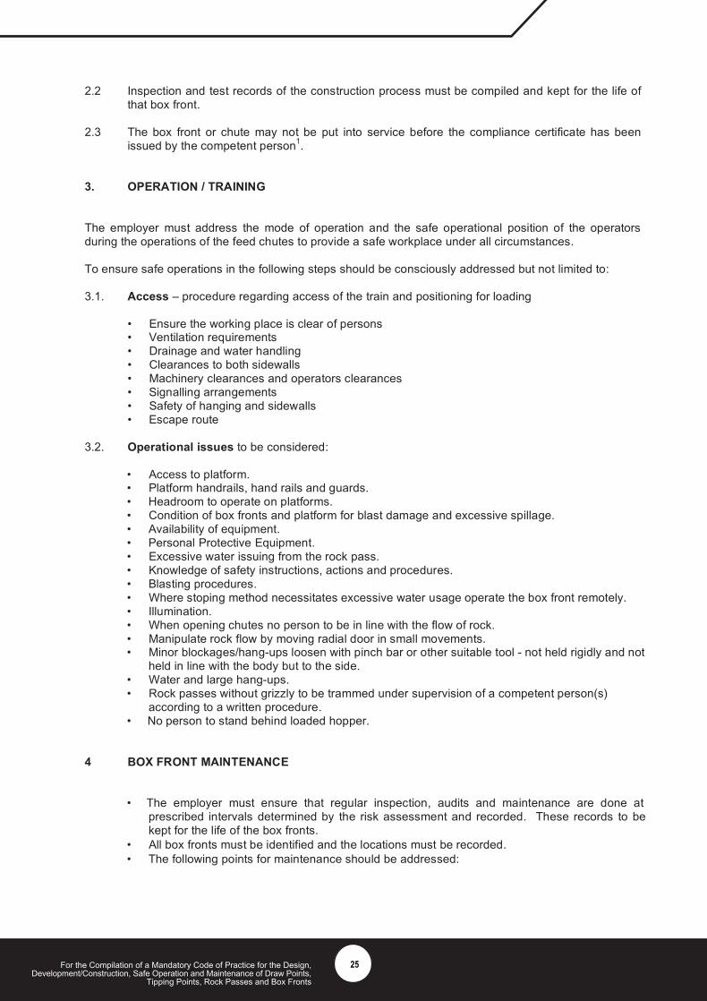
3. OPERATION / TRAINING
The employer must address the mode of operation and the safe operational position of the operatorsduring the operations of the feed chutes to provide a safe workplace under all circumstances.
To ensure safe operations in the following steps should be consciously addressed but not limited to:
3.1. Access – procedure regarding access of the train and positioning for loading
• Ensure the working place is clear of persons• Ventilation requirements• Drainage and water handling• Clearances to both sidewalls• Machinery clearances and operators clearances• Signalling arrangements• Safety of hanging and sidewalls• Escape route
3.2. Operational issues to be considered:
• Access to platform.• Platform handrails, hand rails and guards.• Headroom to operate on platforms.• Condition of box fronts and platform for blast damage and excessive spillage.• Availability of equipment.• Personal Protective Equipment.• Excessive water issuing from the rock pass.• Knowledge of safety instructions, actions and procedures.• Blasting procedures.• Where stoping method necessitates excessive water usage operate the box front remotely.• Illumination.• When opening chutes no person to be in line with the flow of rock.• Manipulate rock flow by moving radial door in small movements.• Minor blockages/hang-ups loosen with pinch bar or other suitable tool - not held rigidly and not
held in line with the body but to the side.• Water and large hang-ups.• Rock passes without grizzly to be trammed under supervision of a competent person(s)
according to a written procedure.• No person to stand behind loaded hopper.
4 BOX FRONT MAINTENANCE
• The employer must ensure that regular inspection, audits and maintenance are done atprescribed intervals determined by the risk assessment and recorded. These records to bekept for the life of the box fronts.
• All box fronts must be identified and the locations must be recorded.• The following points for maintenance should be addressed:
25
For the Compilation of a Mandatory Code of Practice for the Design,Development/Construction, Safe Operation and Maintenance of Draw Points,
Tipping Points, Rock Passes and Box Fronts
• Maintenance permission procedure is applied• Lockout procedure,• Ventilation and gas testing procedure,• Cutting and welding procedures,• Certificate of compliance after completion of maintenance,• Testing the operating mechanisms, and• Opening and closure of rock-passes at box fronts.
Examples of checklists are attached in Annexure B.
26
For the Compilation of a Mandatory Code of Practice for the Design,Development/Construction, Safe Operation and Maintenance of Draw Points,
Tipping Points, Rock Passes and Box Fronts
ANNEXURE “B1”
MAINTENANCE EXAMINATION CHECK LISTSHAFT:__________________ SECTION: ____________ WORKING PLACE:__________
DATE:___________________
No ITEM FOREMANSIGNATURE
1 Hanging wall, sidewall barred and made safe by competent “A” person
2 Stop signs, warning signs, sprags in place
3 Platform
4 Platform barricade
5 Yellow warning signs displayed on platform barricade
6 H – frame condition
7 Stope chute bolts and nuts all in place, secure, type 8.8 high tensile steel
8 Stope chute body undamaged
9 Crevice in order
10 Compressed air cylinder
11 Compressed air leaks
12 Compressed air cylinder attachment points
13 Condition of compressed air hoses, fittings and suspension
14 Record of installation and maintenance of chute
15 Ladder to platform – secure, clearance to rolling stock (500mm)
16 Rail mat or ball & chain condition
17 Rail mat or ball & chain crossbar condition
18 Concrete condition
19 Steelwork condition (visible steel)
20 Remarks:
ENGINEER:__________________________DATE:___________________The original to be filed.
27
For the Compilation of a Mandatory Code of Practice for the Design,Development/Construction, Safe Operation and Maintenance of Draw Points,
Tipping Points, Rock Passes and Box Fronts
ANNEXURE “B2”
FITTER’S MONTHLY CHUTE CONTROL MAINTENANCE CHECK LIST
SECTION:____________LOCATION:___________C = Checked and in order R = Repaired and checked X = Not in order, waiting spares
No ITEMS TO BE INSPECTED DURING MONTHLYEXAMINATIONS