DELTA-THERM Corporation, 6711 Sands Road Suite A, Crystal Lake, IL 60014 (847) 526-2407 Fax (847) 526-4456 (800) 526-7887 CONTENTS page SECTION 1. OVERVIEW 1.1 Precautions........................................................................................ 2 1.2 Cable and components ..................................................................... 2 1.3 General accessories ......................................................................... 2 1.4 Tools recommended ......................................................................... 3 1.5 Site plan ........................................................................................... 3 1.6 Cable storage ................................................................................... 3 1.7 Cable labeling ................................................................................... 3 1.8 Cable testing...................................................................................... 3 1.9 Site preparation ................................................................................. 3 1.10 Proper cable handling ..................................................................... 3 1.11 N.E.C. code ..................................................................................... 3 1.12 Conduit and circuit wire ................................................................... 3 SECTION 2. INSTALLATION 2.1 Slabs: concrete, asphalt, and pavers ................................................ 5 2.2 Stairs: concrete and metal pan ......................................................... 7 2.3 Hangar door rail de-icing .................................................................10 SECTION 3. TESTING AND TROUBLE-SHOOTING 3.1 Pre-installation testing .....................................................................12 3.2 Monitoring cable during installation ................................................12 3.3 Final testing......................................................................................12 3.4 Maintenance ....................................................................................12 3.5 Trouble-shooting and technical support ...........................................12 Installation Instructions MINERAL INSULATED (M.I.) SNOW MELTING CABLE ASSEMBLY Warning: Mineral Insulated Cable must be installed by a qualified electrician. All assembly, installation, and test instructions must be followed. Improper installation can result in property damage, serious injury, or death due to electric shock. Please call Delta-Therm Corporation at 1-800-526-7887 with any installation or operating questions. 1
Transcript
DELTA-THERM Corporation, 6711 Sands Road Suite A, Crystal Lake, IL 60014 (847) 526-2407 Fax (847) 526-4456 (800) 526-7887
Contents pageseCtion 1. Overview
1.1 Precautions ........................................................................................ 21.2 Cable and components ..................................................................... 21.3 General accessories ......................................................................... 2 1.4 Tools recommended ......................................................................... 31.5 Site plan ........................................................................................... 3 1.6 Cable storage ................................................................................... 31.7 Cable labeling ................................................................................... 31.8 Cable testing ...................................................................................... 3 1.9 Site preparation ................................................................................. 31.10 Proper cable handling ..................................................................... 31.11 N.e.C. code ..................................................................................... 31.12 Conduit and circuit wire ................................................................... 3
seCtion 2. iNSTallaTiON2.1 Slabs: concrete, asphalt, and pavers ................................................ 5 2.2 Stairs: concrete and metal pan ......................................................... 72.3 Hangar door rail de-icing .................................................................10
seCtion 3. TeSTiNG aNd TrOuble-SHOOTiNG3.1 Pre-installation testing .....................................................................123.2 Monitoring cable during installation ................................................123.3 Final testing......................................................................................12 3.4 Maintenance ....................................................................................123.5 Trouble-shooting and technical support ...........................................12
installation instructions
Mineral insulated (M.i.) snow Melting Cable asseMbly
warning: Mineral insulated Cable must be installed by a qualified electrician. all assembly, installation, and test instructions must be followed. improper installation can result in property damage, serious injury, or death due to electric shock. Please call delta-Therm Corporation at 1-800-526-7887 with any installation or operating questions.
1
DELTA-THERM Corporation, 6711 Sands Road Suite A, Crystal Lake, IL 60014 (847) 526-2407 Fax (847) 526-4456 (800) 526-7887
1.1 PreCautions
1.2 M.i. Cable and CoMPonents
1.3 General aCCessories
section 1. overview • installation in accordance with the National electric Code and local electrical codes.
do not bend cable within 3” of a termination. (Terminations labeled dO NOT beNdHere)
• do not bend cable tighter than 3” inside diameter.
• do not twist, kink, or spiral the cable.
• do not pull cable from coil. roll coil to unreel cable.
• Test the cable before installation with a 500 vdC insulation resistance tester andmultimeter (ohm meter).
• do not overlap heating cable.
• all related components and controls should be properly rated for the specified locationclassification. do not alter the M.i. cable length in the field, as this will damage the system and voidall warranties.
• Minimum center to center spacing per the NeC is 1”.
• Minimum installation temperature is -20°C
• The metal sheath of the M.i. cable needs to be bonded to a suitable earth terminal.
each M.i. cable assembly is factory terminated. each M.i. snow melt cable assembly includes a base kit. each base kit includes:
• (1) .75” conduit body (C or T type)
• (1) bag of delta dry hydroponic powder
• (1) Piece of duct-seal
• required pressure connector(s)
each M.i. cable has a ul or CSa label attached to the THwN cold lead within 3” of the brass terminating sleeve stating in order:
• Fastening system (as required): nylon cable ties, pre-punched strapping, or metal ties
delta-Therm offers engineered drawing services as outlined in our Price list. if drawings were ordered, please compare the drawing bill of materials to materials supplied with your order and verify that you received all of the delta-Therm components. before starting the installation verify the proper location and layout of heating cable(s), control(s), and/or ac-cessories.
all M.i. cables should be stored in a cool, dry location. Cables should be protected from damage. Following the cable testing instructions in section 4, test all cables removed from storage and record the readings on the warranty card.
delta-Therm Mineral insulated Heating Cables are ul listed and CSa certified for embed-ded applications in concrete, asphalt, and paver based products. each cable has a ul or CSa label attached to the THwN cold lead within 3” (76mm) of the metal sleeve. The label states the following information in order: cable type (prefix, number of conductors, and cable resistance), cable length, operating voltage, current draw, total wattage, watts per lineal foot, and cold lead length. The cable has a standard THwN cold length of 10’ (3m).
Please refer Section 3 for all cable testing procedures.
review installation, engineering, electrical, and or architectural drawings prior to installa-tion. verify that available voltage is the same as the cable operating voltage indicated on the ul or CSa label. install conduit from the cable feed points to an indoor or dry junction box, continuing to the power panel per site plan. install appropriate grounding system per prevailing electrical code.
Provide a system for relief of condensation or moisture in the conduit system.install conduit expansion joints anywhere the conduit crosses a planned expansion joint. be sure the ground is maintained across the expansion joint.
Cap or plug all conduit openings temporarily before installing the M.i. cable, ensure that all surfaces which the cable may come in contact with are free from sharp edges and protect cable from items that may cut or cause damage.
always unroll the coil of M.i. cable. do not pull the cable in a helix fashion. Please refer to detail 1 and detail 17 to review single and dual conductor cable finished assembly and base kit components.
Please consult NeC article 426 Fixed Outdoor electric deicing and Snow-Melting equip-ment with attention to:
Section 426.20 embedded deicing and Snow-Melting equipment.
Section 426-13 identification The presence of outdoor electric deicing and snow-melting equipment shall be evident by the posting of appropriate caution signs or markings where clearly visible.
The cable assemblies require a permanently wired and grounded conduit system. use only ul listed (CSa Certified) weatherproof junction boxes.
3
DELTA-THERM Corporation, 6711 Sands Road Suite A, Crystal Lake, IL 60014 (847) 526-2407 Fax (847) 526-4456 (800) 526-7887
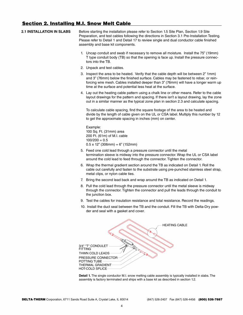
2.1 installation in slabs before starting the installation please refer to Section 1.5 Site Plan, Section 1.9 Site Preparation, and test cables following the directions in Section 3.1 Pre-installation Testing. Please refer to detail 1 and detail 17 to review single and dual conductor cable finished assembly and base kit components.
1. uncap conduit and swab if necessary to remove all moisture. install the 75” (19mm)T type conduit body (Tb) so that the opening is face up. install the pressure connec-tors into the Tb.
2. unpack and test cables.
3. inspect the area to be heated. verify that the cable depth will be between 2” 1mm)and 3” (76mm) below the finished surface. Cables may be fastened to rebar, or rein-forcing wire mesh. Cables installed deeper than 3” (76mm) will have a longer warm uptime at the surface and potential less heat at the surface.
4. lay out the heating cable pattern using a chalk line or other means. refer to the cablelayout drawings for the pattern and spacing. if there isn’t a layout drawing, lay the zoneout in a similar manner as the typical zone plan in section 2.3 and calculate spacing.
To calculate cable spacing, find the square footage of the area to be heated anddivide by the length of cable given on the ul or CSa label. Multiply this number by 12to get the approximate spacing in inches (mm) on center.
example:100 Sq. Ft. (31mm) area200 Ft. (61m) of M.i. cable100/200 = 0.50.5 x 12” (306mm) = 6” (152mm)
5. Feed one cold lead through a pressure connector until the metaltermination sleeve is midway into the pressure connector. wrap the ul or CSa labelaround the cold lead to feed through the connector. Tighten the connector.
6. wrap the thermal gradient section around the Tb as indicated on detail 1. roll thecable out carefully and fasten to the substrate using pre-punched stainless steel strap,metal clips, or nylon cable ties.
7. bring the second lead back and wrap around the Tb as indicated on detail 1.
8. Pull the cold lead through the pressure connector until the metal sleeve is midwaythrough the connector. Tighten the connector and pull the leads through the conduit tothe junction box.
9. Test the cables for insulation resistance and total resistance. record the readings.
10. install the duct seal between the Tb and the conduit. Fill the Tb with delta-dry pow-der and seal with a gasket and cover.
2/8/12SCALE:MI-16 SINGLE CONDUCTOR MI CABLE ASSEMBLY
NTS
detail 1. The single conductor M.i. snow melting cable assembly is typically installed in slabs. The assembly is factory terminated and ships with a base kit as described in section 1.2.
4
DELTA-THERM Corporation, 6711 Sands Road Suite A, Crystal Lake, IL 60014 (847) 526-2407 Fax (847) 526-4456 (800) 526-7887
THE T-TYPE CONDUIT BODY IS NOT A SPLICE BOX. THE TB IS EMBEDDED IN THE NONCOMBUSTIBLE MEDIUM.
2/2/12
M.I. SNOW MELT CABLE
CABLE OFF-SET(TYPICALLY 3")
SCALE:SM-111 PLAN OF TYPCIAL SNOWMELTING LAYOUT
NTS
S
SLAB SENSOR
M.I. THERMAL GRADIENT SECTION M.I. CABLE
COLD LEADS
CABLE SPACING(TYPICALLY 6-9")
2.1 slabs: ConCrete, asPHalt, and PaVers
section 2. installation
detail 2. Plan of single conductor M.i. cable entry into the T type conduit body (Tb). Pull cold leadsthrough conduit and instal duct seal. Fill the conduit body with delta-dry power, install gasket and cover.
detail 3. Typical single conductor cable layout for a zone plan. The thermal gradient section is crossed over itself.
detail 4. expansion joint detail using a minimum 14”x16”x8” size malleable iron box under the slab. box to be filled with sand.EXPANSION JOINT DETAIL USING A MINIMUM 14"x16"x8" SIZE MALLEABLE IRON BOX UNDER THE SLAB. BOX TO BE FILLED WITH SAND.
2/2/12SCALE:SM-122 EXPANSION JOINT SECTION
NTS
SNOW MELT CABLE
T-TYPE CONDUIT BODY
2/2/12SCALE:2.31 PLAN OF T-TYPLE UNILET
NTS
22"
4"
5
DELTA-THERM Corporation, 6711 Sands Road Suite A, Crystal Lake, IL 60014 (847) 526-2407 Fax (847) 526-4456 (800) 526-7887
section 2. installation2.1 slabs: ConCrete, asPHalt, and PaVers
detail 5. Cables attached to rebar in a single pour concrete system.
detail 6. Cables covered in a concrete cap over concrete.
detail 7. Cables covered in asphalt cap, over asphalt.
CONCRETE 2"-3" COVER
M.I. SNOW MELT CABLEATTACHED TO REBAR
GRAVEL BASE
UNDISTURBED EARTH
WIRE MESH
2/2/12SCALE:2.54 SINGLE-POUR CONCRETE SECTION
NTS
SLAB SENSOR
S
WIRE MESH
UNDISTURBED EARTH
GRAVEL BASE
M.I. SNOW MELT CABLEATTACHED TO MESH
CONCRETE CAP 2"-3"
2/2/12SCALE:2.65 TWO-POUR CONCRETE SECTION
NTS
CONCRETE BASE
SLAB SENSOR
S
GALVANIZED OR STAINLESSSTEEL STRAPPING
UNDISTURBED EARTH
M.I. SNOW MELT CABLE
ASPHALT 2"-3" COVER
ASPHALT BASE
2/2/12SCALE:SM1 ASPHALT SECTION
NTS
SLAB SENSOR
S
6
DELTA-THERM Corporation, 6711 Sands Road Suite A, Crystal Lake, IL 60014 (847) 526-2407 Fax (847) 526-4456 (800) 526-7887
NTSbefore starting the installation please refer to Section 1.5 Site Plan, Section 1.9 Site Preparation, and test cables following the directions in Section 3.1 Pre-installation Testing. Please refer to detail 1 and detail 17 to review single and dual conductor cable finished assembly and base kit components.
1. identify all areas where handrail holes are located or will be cored, and identify whereany penetrations to the concrete will occur, ie. signage, drains, or other.
2. uncap conduit and swab if necessary to remove all moisture. install the ¾” (19mmconduit body supplied with the Mi cable to the conduit. Position the conduit body withthe opening facing up. install the provided pressure connector in the conduit body.
3. unpack and test the M.i. cable per the cable instructions.
4. inspect the area to be heated. verify that the cable depth will be 2” from the finishedsurface of the stairs. verify rebar or other cable supporting devices are in place andsecured.
5. refer to the cable layout drawings for the pattern and spacing required.
6. insert one of the THwN wire cold leads (if using single conductor M.i. cable) or bothTHwN wire cold leads (if using a two conductor M.i. cable) into the compressionconnector and out of the conduit body. be careful not to damage the wire insulation.Continue until the metal sleeve (where the wire connects to the M.i. cable) is midwaythrough the compression connector. The cable ul or CSa label will need to wraparound the cold lead to feed through the connector. Tighten the connector. Positionthe wire as to avoid damage.
7. Position the thermal gradient section of the Mi cable as shown in the cable layoutdrawing. Caution: do not bend the cable at the hot/cold junction (where largerdiameter thermal gradient fitting connects to smaller diameter heating section of theMi cable).
8. roll the M.i. cable out and position per the cable layout drawing. attach the cable withpre-punched stainless steel strap, metal clips, or nylon cable ties as shown in thecable layout drawing.
7
DELTA-THERM Corporation, 6711 Sands Road Suite A, Crystal Lake, IL 60014 (847) 526-2407 Fax (847) 526-4456 (800) 526-7887
2.2 stairs: ConCrete and Metal Pan
section 2. installation
9. when installing a single conductor Mi cable the end of the cable must return to theconduit body. a second compression fitting should be installed into the T type conduitbody. The cold lead wire shall feed through the compression fitting and out of theconduit body. Tighten the connector.
10. Pull the two cold lead wires through the ¾” conduit to the junction box or controlequipment. Test the cable at the junction box or control equipment for insulationresistance and total resistance. record these readings.
11. install the duct seal between the conduit body and connecting 3/4” conduit. Fill theconduit body with the supplied delta-dry powder and seal with the gasket and cover.
12. do not apply power to the cable. The cable is must be embedded in concrete and theconcrete sufficiently cured prior to energizing the cable.
CONCRETE EMBEDDED MI CABLE
M.I. SNOW MELT CABLE
2/2/12SCALE:3.39 STAIR SIDE VIEW
NTS
detail 10. Side view of M.i. cable installed in concrete stairs. Secure cable in place using rebar, mesh or other means to maintain cable spacing. install cable at depth of 2-3” below finished surface.
M.I. SNOW MELT CABLE
SLAB SENSOR
CONCRETE EMBEDDED MI CABLE
2/2/12SCALE:3.310 STAIR PERSPECTIVE
NTS
S
detail 11. Perspective view of M.i. cable installed in new set of concrete stairs. Secure cable in place using rebar, mesh or other means to maintain cable spacing. install cable at depth of 2-3” belowfinished surface. install slab sensor between two cables.
CONCRETE STAIRS AND LANDING:ATTACH CABLE TO SURFACE USING STRAPPING OR CLIPS.
M.I. SNOW MELT CABLE
NOTCHES
SLAB SENSOR
NOTCH
2/2/12SCALE:3.411 EXISTING STAIR PERSPECTIVE
NTS
S
detail 12. Perspective view of M.i. cable installed in existing set of concrete stairs. Secure cable in place using rebar, mesh or other means to maintain cable spacing. install cable at depth of 2-3” below finished surface. install slab sensor between two cables.
8
DELTA-THERM Corporation, 6711 Sands Road Suite A, Crystal Lake, IL 60014 (847) 526-2407 Fax (847) 526-4456 (800) 526-7887
section 2. installation
2.2 stairs: ConCrete and Metal Pan
detail 13. Side view of M.i. cable installed in metal pan stairs. install one dual conductor cable per tread at depth of 2-3” below finished surface.
detail 14. Side view of M.i. cable conduit bodies in stringer.
PAN
STRINGER
M.I. SNOW MELT CABLE
LANDING
DRILL THROUGH PAN AND
STRINGER FOR CONDUIT
BODY CONNECTION.
2/2/12
METAL PAN STAIRSCONCRETE EMBEDDED MI CABLE
SCALE:3.513 STRINGER SIDE VIEW
NTS3/4" CONDUIT
3/4" CONDUIT BODIES SUPPLIED WITH M.I. CABLE
CONCEALING COVER BY OTHERS.
3/4" CONDUIT
2/2/12
METAL PAN STAIRS
CONCRETE EMBEDDED MI CABLE
SCALE:3.514 STRINGER SIDE VIEW
NTSM.I. CONDUIT BODYUNDER STAIR AND EMBEDDED.
3/4" CONDUIT
2/2/12
METAL PAN STAIRS
CONCRETE EMBEDDED MI CABLE
SCALE:3.515 PLAN VIEW LANDING
NTS
S
SLAB SENSOR
M.I. SNOW MELT CABLE
detail 15. Plan view of M.i. cable in a metal pan stair landing.
9
DELTA-THERM Corporation, 6711 Sands Road Suite A, Crystal Lake, IL 60014 (847) 526-2407 Fax (847) 526-4456 (800) 526-7887
2.2 stairs: ConCrete and Metal Pan
2.3 de-iCinG HanGAr door rails
section 2. installationSTRINGER
TOP LANDING
2/2/12SCALE:3.516 STAIRS & LANDING PLAN
NTS
S
M.I. SNOW MELT CABLE
before starting the installation please refer to Section 1.5 Site Plan, Section 1.9 Site Preparation, and test cables following the directions in Section 3.1 Pre-installation Testing. Please refer to detail 1 and detail 17 to review single and dual conductor cable finished assembly and base kit components.
1. do not place the cable in direct contact with the rail.
2. M.i. cable is to be embedded in concrete only for this application. do not install theheated section in conduit. The only portion that can be placed in conduit is the THwNcold lead.
3. Space the cable 3 inches from the rail laterally and 2 inches from the finished concretesurface.
4. Place a 2 inch diameter semi-circle loop downward every 20 feet of straight Mi cablefor thermal expansion.
5. if snow melting adjacent area, space adjacent cable(s) on 6 inch centers into theadjacent area to be snow melted.
6. M.i. cable may be installed in a two pour type manner to eliminate saw cutting of con-crete. The cable may be installed in a single pour manner by attaching cable to rebar,mesh, or other elevating or stand-off means.
7. The sensor for the automatic snow melting control system must be placed withinthe heated area of the slab, also in an area most indicative of snow conditions. Thesensor shall not be obstructed from contact with falling snow, wind-blown snow, ormoisture from the melting snow and ice through the course of de-icing.
8. No outdoor electrical splices are required. The M.i. cable shall be supplied with inte-gral non-heating (cold-lead) connection wire of sufficient length to be routed throughconduit to an indoor, appropriately rated junction box or power control device. Mountall electrical controls at least 48” above finished floor in an ordinary location.
9. The required amount of branch circuits shall route to a NrTl listed contactor typepower switching panel. The non-heating M.i. cable lead wire shall route to this panel.
10. The automatic snow melting control system shall control the contactor type panel byswitching 120vaC to the contactor coils. The embedded snow/moisture sensor andambient over-ride thermostat shall be 24 vdC class 2 wiring.
detail 16. Plan view of M.i. cable in a metal pan stair landing.
10
DELTA-THERM Corporation, 6711 Sands Road Suite A, Crystal Lake, IL 60014 (847) 526-2407 Fax (847) 526-4456 (800) 526-7887
2.3 de-iCinG HanGAr door rails
section 2. installation
detail 17. dual conductor M.i. snow melting cable assembly is installed to de-ice hangar door rails. The assembly is factory terminated and ships with a base kit as described in section 1.2.
PRESSURE CONNECTOR
HOT-COLD SPLICE
HEATING CABLE
END CAP
3/4" "C"CONDUIT FITTING
THHNCOLD LEADS
2" FROM FINISHED DRAIN SURFACE
FINISHED SURFACE
M.I. SNOW MELT CABLE
M.I CABLE EMBEDDED IN CONCRETE:
RE-BAR
CHAIR
2/2/12SCALE:4.321 HANGAR RAIL SECTION
NTS
3"3"
detail 18. install dual conductor M.i. cable in new hanger rail installation. embed cable 3” from rail and 2” below finished drain surface. Please refer to door rail manufacturer for exact rail configuration.
2" FROM FINISHED DRAIN SURFACE
FINISHED SURFACE
M.I. SNOW MELT CABLE
SAW-CUT INTO EXISTING CONCRETE:
2/2/12SCALE:4.422 EXISTING HANGAR RAIL SECTION
NTS
3"3"
detail 19. install dual conductor M.i. cable in existing hangar rail installation. Saw cut and embed cable 3” from rail and 2” below finished drain surface. Please refer to door rail manufacturer for exact rail configuration.
BEND STRAIGHT RUNS OF CABLE EVERY 20'
2/2/12SCALE:4.523 THERMAL EXPANSION BENDS
NTS
2"
20'-0"
2"
detail 20. bend straight runs of M.i. cable every 20’ for thermal expansion.
11
DELTA-THERM Corporation, 6711 Sands Road Suite A, Crystal Lake, IL 60014 (847) 526-2407 Fax (847) 526-4456 (800) 526-7887
section 3. testing and trouble-shooting 3.1 Pre-installation testinG
3.2 MonitorinG Cable durinG installation
3.3 Final testinG
3.4 MaintenanCe
3.5 trouble-sHootinG and teCHniCal suPPort
unpack the M.i. cable and test each cable for insulation resistance (ir), and total resis-tance (Tr).
To test Tr, connect each lead of the ohmmeter to each M.i. cable cold lead conductor. Test in accordance with the meter manufacturer’s instructions. Compare Tr reading from ohm-meter to calculated Tr (multiply the heated length of cable by the cable resistance value found on ul/CSa label). The ohmmeter reading should be within 10% of the calculated Tr.
To test ir, connect one lead of the 500 vdC insulation resistance tester to one cold lead conductor and the other lead to the M.i. cable metal sheath. Test in accordance with the meter manufacturer’s instructions. ir reading should be greater than 10 megohms.
Please enter the Tr and ir readings on the warranty card.
repeat the steps as described in Section 3.1 and enter the information on the warranty card. if there is a change in the meter reading, please check the cable for damage, as well as any power connections, splices, and end terminations.
repeat the ir test steps as described in Section 3.1. To test Tr, connect each lead from the ohmmeter to the two cold leads that will be attached to power. enter the information on the warranty card. if there is a change in the meter reading, please check the cable for damage, as well as any power connections, splices, and end terminations.
annually check system for loose or damaged cable.
if during any test the meter readings vary by +/- 10% from the previous test, stop the instal-lation and investigate. Please check for pinched or crushed cables, test splices, test power connections, test end terminations, and repair accordingly. Check for water in all junction boxes or conduit. any faults should be repaired by a qualified electrician or factory techni-cian before the final pour is made.
For additional trouble-shooting and repair procedures, please contact delta-Therm techni-cal support at 1-800-526-7887. Please be prepared to provide:
• Part numbers for all installed equipment
• ir and Tr readings on all installed cables
• verification that incoming voltage matches design voltage of delta-Therm equipment
• verification that you have checked all wiring, junction boxes, etc.
• digital photos of installed equipment
if you have any questions or comments about these instructions or your installation please call delta-Therm at 1-800-526-7887.


![Chapter 20 - d-block metal chemistry - coordination complexesmichael.lufaso/chem3610/Inorganic_Chapter20.pdf · 2fwdkhgudo fu\vwdo ilhog vwdelol]dwlrq hqhujlhv &)6( iru g q frqiljxudwlrqv](https://static.documents.pub/doc/80x56/5c66c1f809d3f2f91c8cc90e/chapter-20-d-block-metal-chemistry-coordination-complexes-2fwdkhgudo-fuvwdo.jpg)


