21
WSD-1004 07 2016 WANCO | 5870 Tennyson Street, Arvada, Colorado 80003 USA | 303-427-5700 www.wanco.com MINI THREE-LINE MESSAGE SIGNS MODEL WVT3 PRODUCT SPECIFICATIONS | JULY 2016

WSD-1004 07 2016
WA NCO | 58 70 T en ny so n S tr ee t , Arv ad a, Co lora do 8 0003 U S A | 3 03- 42 7-5 700 www.wanco.com
MINI THREE-LINE MESSAGE SIGNS MODEL WVT3 PRODUCT SPECIFICATIONS | JULY 2016
W a n c o ® M i n i T h r e e - L i n e M e s s a g e S i g n s P a g e 2 o f 2 1 P r o d u c t S p e c i f i c a t i o n s | J u l y 2 0 1 6
WA NCO | 58 70 T en ny so n S tr ee t , Arv ad a, Co lora do 8 0003 U S A | 3 03- 42 7-5 700 www.wanco.com All information subject to change without notice. All trademarks are property of their respective owners.
1. SYSTEM
1.1. Description Wanco® message signs provide information to the public on a large, legible LED display. These signs are portable and self-powered, requiring no permanent installation or wiring. Wanco mini matrix signs are a compact version of Wanco’s full-size variable message signs, about 30% smaller, making them highly maneuverable and easy to deploy.
The three-line display can present text messages of one, two, or three lines of up to eight characters per line. Messages are programmed using a self-contained onboard controller, making a laptop or external controller unnecessary. Signs come configured with preprogrammed standard messages, and users can create custom messages easily.
For optimal positioning, the sign rotates independent of the trailer and its height is fully adjustable. Jack-legs and optional provide more adjustability and added stability. The trailer is easy to maneuver and deploy, and can be towed by most vehicles.
Power is provided by batteries, which are charged by an automated solar charging system.
1.2. Models
1.2.1. WVT3(A) Mini three-line message sign with hydraulic lift
1.2.2. WVT3(B) Mini three-line message sign with hand-operated winch
1.3. Temperature limits Operating –29 to 165°F (–34 to 74°C) Storage –40 to 185°F (–40°C to 85°C)
1.4. Standards Compliant in accordance with:
NTCIP Version 2 NEMA TS 4-2005 Section 2 for ambient temperature, vibration, shock, electro-static discharge (ESD), and radio interference
2. FEATURES
2.1. Setup • Hydraulic lift or winch with cable raises sign display on tower • Tower rotates 360 degrees for optimal positioning • Single disk brake holds display in place during operation, while a cradle supports and
holds display in travel position
2.2. Operation • Self-contained onboard control system, no laptop required • Full-color touchscreen controller with high-resolution display • Multi-level password protection restricts access to control software • Preprogrammed text messages • Internal clock facilitates built-in schedule programming • Multiple alphanumeric fonts • Control box can be locked to prevent unauthorized access • Optical lenses and sunshades increase visibility and performance
W a n c o ® M i n i T h r e e - L i n e M e s s a g e S i g n s P a g e 3 o f 2 1 P r o d u c t S p e c i f i c a t i o n s | J u l y 2 0 1 6
WA NCO | 58 70 T en ny so n S tr ee t , Arv ad a, Co lora do 8 0003 U S A | 3 03- 42 7-5 700 www.wanco.com All information subject to change without notice. All trademarks are property of their respective owners.
• Cooling fans protect sign cabinet from overheating • Optional outriggers widen footprint for added stability • NTCIP compliant
2.3. Power system • Battery powered and solar charging • Energy-efficient operation results in long run times • Solar panels charge batteries automatically without intervention • Charging system shuts down when batteries are fully charged, preventing damage • Power system allows battery charging with solar panels or commercial power • Cooling fan protects battery charger from overheating • Battery box can be locked to prevent unauthorized access
2.4. Maintenance • Individual character modules can be replaced easily • Standard trailer tires • Heavy-duty bolt-on steel fenders can be replaced if damaged • Durable powder-coat finish resists the elements
2.5. Application Common applications include:
• Roadwork zones • Traffic calming • Road closures • Emergency response • Public events
3. DISPLAY
3.1. Cabinet
3.1.1. Description Weather-resistant cabinet contains display modules and related electronics. Hinged door with full-size display window protects electronics and provides access for maintenance. Clasps hold door closed during operation and can be locked with user-supplied padlock.
Cabinet face is tapered five degrees downward (it is wider at the top than at the bottom) to face traffic, reducing glare.
3.1.2. Size 96" x 55" x 12" (244 x 140 x 30cm)
3.1.3. Material Aluminum sheet, 5052-H32, 0.062" (1.575mm) thick
3.1.4. Construction Panels are riveted together, with internal ribs to add lateral strength
3.1.5. Door Cabinet door is aluminum extruded frame with sheet metal corner brackets. Stainless steel butt hinges are bolted to top of cabinet and door.
Window is anti-glare Lexan® solar-grade polycarbonate, 0.150" (3.81mm) thick. Bulb-type weather seal ensures tight fit and seal between window and door frame.
When sign is in stored position, door fully opens to service the sign cabinet interior. Telescoping prop-slides, one on each side of the cabinet, hold door open.

W a n c o ® M i n i T h r e e - L i n e M e s s a g e S i g n s P a g e 4 o f 2 1 P r o d u c t S p e c i f i c a t i o n s | J u l y 2 0 1 6
WA NCO | 58 70 T en ny so n S tr ee t , Arv ad a, Co lora do 8 0003 U S A | 3 03- 42 7-5 700 www.wanco.com All information subject to change without notice. All trademarks are property of their respective owners.
3.1.6. Finish Cabinet and door are coated with oven-baked, flat-black, powder-coat finish to ensure durability and corrosion protection. Assemblies are high-pressure phosphate-washed prior to finish coat.
3.1.7. Wiring Wiring service loop from control box to display cabinet is routed inside liquid-tight loom and P-clamped to trailer frame. Service loop length is designed to allow 360-degree sign rotation. All wiring connectors and procedures are per CSA standards.
3.1.8. Ventilation Two cooling fans located at the top of the display cabinet circulate air into, through, and out of the cabinet to cool electrical components. A duct is located at the top of the cabinet to ensure even airflow.
It is proven that electronic components, including LEDs, degrade in conditions of extreme heat. Without the cooling fans the display cabinet can reach over 200 degrees Fahrenheit.
A temperature sensor is mounted on the photocell PC board inside the cabinet to control fan operation. Each fan has its own thermal settings, adjustable with the onboard computer, to optimize battery power usage.
3.1.9. Storage When lowered for storage and transport, the display cabinet rests in two support cradles, parallel to the trailer length, no locking pins required
3.2. Display panel
3.2.1. Description The display panel is comprised of a series of display modules laid out in a grid across the inside of the display cabinet. Each module has a matrix of LEDs installed on its face, which light up to show one character of the configured message. Each module features the necessary electronics and coatings to ensure outstanding performance and durability.
3.2.2. Display modules Modular design Allows any display module to be installed in any position in the matrix without repositioning DIP switches
Wiring Modules have quick-connect electrical connectors for easy servicing. All wiring terminates at a single terminal strip inside the display cabinet.
Replacement Each module can be exchanged in less than two minutes. The only tool needed is a 5/16-inch nut driver socket or slotted screwdriver
After a new module is installed, a one-step initialization process causes each module to sense its position in the full-matrix display. Initialization is accomplished using the sign’s controller.
Size 9.5" (24.1cm) wide by 14.5" (36.8cm) high, nominal
Spacing 3" horizontal spacing, 4" vertical spacing

W a n c o ® M i n i T h r e e - L i n e M e s s a g e S i g n s P a g e 5 o f 2 1 P r o d u c t S p e c i f i c a t i o n s | J u l y 2 0 1 6
WA NCO | 58 70 T en ny so n S tr ee t , Arv ad a, Co lora do 8 0003 U S A | 3 03- 42 7-5 700 www.wanco.com All information subject to change without notice. All trademarks are property of their respective owners.
Material FR4 glass-reinforced epoxy laminate, double-sided, black solder mask with white silkscreen
Board thickness, 0.094" (2.388mm)
Copper size, 1 oz. (28.4g)
Coating 5-mil, military-spec, low-VOC, silicone conformal coating (Dow Corning 1-2577) provides long-term protection against moisture and other atmospheric contaminants, resists corrosion and shorts due to high humidity
Vibration mounts All display modules are mounted on rubber vibration-isolation mounts, decreasing risk of physical shock during transport and isolating characters from chassis ground
Humidity limits Conformal coating rated to 95% relative humidity
3.2.3. Pixels Four LEDs form a “pixel”
Pixel size 0.75" x 0.75" (19 x 19mm)
Display module 5 x 7 pixels (W x H), 35 pixels total
Pixel pitch 54mm, horizontal and vertical
3.2.4. LEDs Technology AlInGaP II (aluminum indium gallium phosphide) technology, T-1¾ size, through-hole auto-insertion
Color range Amber, 589.5 to 592 nm
Current 100 mA peak-pulsed forward current
3.2.5. Lenses and visors Each pixel has a snap-in optical lens over the LEDs, enhancing the brightness and angularity of each pixel while reducing power consumption. A polycarbonate visor shades each row of pixels to eliminate glare caused by direct sun exposure. The sunshades snap onto the display module without tools. The lenses snap into the sunshades.
These enhancements enable the message sign to operate with approximately half the power consumption of other message signs. As a result, the system is fully functional using fewer solar panels and batteries, while providing outstanding brightness and readability in all lighting conditions, and 30-day battery autonomy without sun. Reducing the number of solar panels and batteries also lowers the trailer weight and reduces maintenance costs.
3.2.6. Visibility 4800 ft. (1463m) per 2008 NTPEP results
3.2.7. Legibility Word recognition with default font, 582 to 712 ft. (177 to 217m) per 2008 NTPEP results
3.2.8. Viewing angle Total viewing area with optical lenses, 46.4 to 51.6 degrees per 2008 NTPEP results
3.2.9. Brightness Factory preset for optimal viewing and power consumption

W a n c o ® M i n i T h r e e - L i n e M e s s a g e S i g n s P a g e 6 o f 2 1 P r o d u c t S p e c i f i c a t i o n s | J u l y 2 0 1 6
WA NCO | 58 70 T en ny so n S tr ee t , Arv ad a, Co lora do 8 0003 U S A | 3 03- 42 7-5 700 www.wanco.com All information subject to change without notice. All trademarks are property of their respective owners.
3.2.10. Auto dimming Two photocells detect ambient light on the message sign; the message sign computer adjusts the brightness of the LEDs accordingly, dimming display brightness in darkness, increasing to full brightness in daylight
Photocells are mounted inside the sign cabinet, one facing rear and one facing front
3.2.11. Software design Driver LEDs controlled through 30mA pulse-width modulation design
Addressing Each display module address is selected through a software command; no DIP switches are used. The address does not change until reprogrammed, preventing the message from shifting due to an individual module failure.
Pixel test Each module is equipped with individual pixel failure notification
3.2.12. Font 5 x 7 pixels (W x H)
Equivalent size: 10.41" x 14.67" (325 x 457mm)
Physical size: 9.25" x 13.51" (235 x 343mm)
3 lines of 8 letters per line, maximum
4. CONTROL SYSTEM
4.1. Description Self-contained onboard computer, comprised of a power control unit (PCU), located behind display modules inside the message sign display cabinet; and a display control unit (DCU), located inside control box on the back of the message sign display cabinet.
4.2. Control box
4.2.1. Size 12.3" x 11.7" x 5.3" (31.2 x 29.7 x 14.4 cm) W x H x D
4.2.2. Material 0.08" aluminum
4.2.3. Mounting Securely fastened to the sign cabinet with six mounting screws
4.2.4. Door Front-panel is a door, hinged on the left, which opens fully.
4.2.5. Latch Two quarter-turn latches on front of control box door keep hinged door closed. Both latches are keyed and can be locked.
4.2.6. Finish Cabinet and door are coated with oven-baked, equipment-white, powder-coat finish to ensure durability and corrosion protection. Assemblies are high-pressure phosphate-washed prior to finish coat.
W a n c o ® M i n i T h r e e - L i n e M e s s a g e S i g n s P a g e 7 o f 2 1 P r o d u c t S p e c i f i c a t i o n s | J u l y 2 0 1 6
WA NCO | 58 70 T en ny so n S tr ee t , Arv ad a, Co lora do 8 0003 U S A | 3 03- 42 7-5 700 www.wanco.com All information subject to change without notice. All trademarks are property of their respective owners.
4.3. Control panel
4.3.1. Touchscreen Display Full color, backlit, 7-inch display
Capacitive touch panel
800 x 480 pixels, W x H
Display automatically shuts off after 10 minutes of inactivity
Interface Menu-based structure, accessed with virtual buttons on the touchscreen display, provides access to all sign functions including programming messages
Virtual keyboard appears when required for text entry
Multi-level password protection restricts access
4.3.2. LED indicators Indicates the following status conditions:
Solar charging system is charging batteries System power shutdown occurred Programmed schedule is active Power to optional radar device is on
4.3.3. Data port 1 USB port for connecting optional handheld touchscreen controller and for downloading data from optional traffic data collector (if installed)
See “Options and Optional Equipment”
4.4. PC boards
4.4.1. Coating 100% coated with military-spec, low-VOC, silicone conformal coating to provide long-term protection against moisture and other atmospheric contaminants. Resists corrosion and shorts due to high humidity.
4.4.2. Humidity limits Conformal coating rated to 95% relative humidity
4.5. Serviceability Four plunger panel latches allow the control panel to be removed, providing access to internal components inside control box; PCU is accessible by removing display modules inside message sign display cabinet.
All wiring connections have quick-connect plugs.
4.6. Controller software
4.6.1. Standards Fully NTCIP-compliant
4.6.2. Security Three levels of password protection
4.6.3. Message programming
Instant access to program new messages Extremely easy to program

W a n c o ® M i n i T h r e e - L i n e M e s s a g e S i g n s P a g e 8 o f 2 1 P r o d u c t S p e c i f i c a t i o n s | J u l y 2 0 1 6
WA NCO | 58 70 T en ny so n S tr ee t , Arv ad a, Co lora do 8 0003 U S A | 3 03- 42 7-5 700 www.wanco.com All information subject to change without notice. All trademarks are property of their respective owners.
4.6.4. Message types Quick-messages Easy quick-message activation
Permanent Easy quick-message activation
Changeable Over 90 preprogrammed permanent messages, including arrows and FHWA standards
Temporary 250 changeable messages stored in NV flash
Blank 10 temporary or volatile messages, for ITS systems
4.6.5. Interface display WYSIWYG (What You See Is What You Get) while programming
4.6.6. Text alignment Selectable: left, center, or right
4.6.7. Blinking Each character can individually blink
Individual lines of a multi-line message can blink
The entire message can blink
Adjustable timing and duty cycle
4.6.8. Message pages Maximum 10 sequential “pages” per message, sequencing speed from 0.1 to 25.5 sec.
4.6.9. Scheduling Real-time clock and calendar with DST control
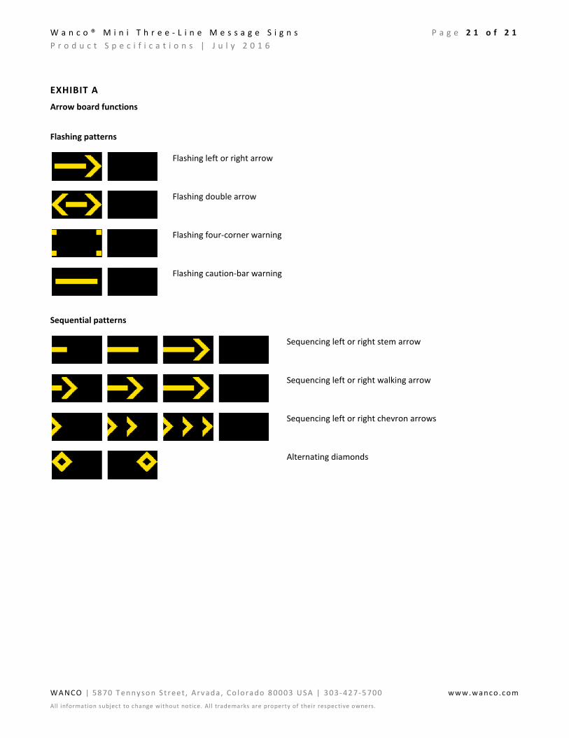
4.6.10. Arrow board functions
Sign can display any of the following 12 full-size arrow functions
Modes Flashing left or right arrow Flashing double arrow Flashing four-corner warning Flashing caution-bar warning Sequencing left or right stem arrow Sequencing left or right walking arrow Sequencing left or right chevron arrows Alternating diamonds
(for samples, see Exhibit A)
Bold graphics Each arrow and bar is 5 pixels wide
One-click activation All modes can be activated using keyboard function keys
4.6.11. Configuration Menus provide access to all message sign configuration settings
4.6.12. Troubleshooting System status on main screen, detailed status and diagnostic menus provide additional message sign information to assist in troubleshooting

W a n c o ® M i n i T h r e e - L i n e M e s s a g e S i g n s P a g e 9 o f 2 1 P r o d u c t S p e c i f i c a t i o n s | J u l y 2 0 1 6
WA NCO | 58 70 T en ny so n S tr ee t , Arv ad a, Co lora do 8 0003 U S A | 3 03- 42 7-5 700 www.wanco.com All information subject to change without notice. All trademarks are property of their respective owners.
5. TRAILER
5.1. Frame All welded structural steel
5.2. Fenders Round full wheel coverage fenders with inner splash panel on each fender. Fenders are bolted to the trailer frame.
Material: 16ga steel
5.3. Tie-downs One on each corner of frame
5.4. Finish Frame is coated with oven-baked, safety-orange powder-coat finish to ensure durability and corrosion protection. Assemblies are run through a five-stage, high-pressure phosphate-wash prior to finish coat.
See “Options and Optional Equipment” for color options.
5.5. Axle assembly 2000 lb. (907kg) capacity, 5 on 4.5" B.C. idler hub
5.6. Springs Double-eye leaf springs
5.7. Tires ST205/75D15 steel-belted trailer tires, load rating B
5.8. Drawbar
5.8.1. Construction Telescopes inside receiver sleeve welded under trailer frame. Removable for shipping and for added theft protection if needed. Secures with two 1/2-inch diameter bolts.
5.8.2. Material Square tubing, 3" x 3/16" wall (7.62cm x 0.476cm wall)
5.8.3. Jack Top-wind swivel, 800-lb. (363kg) capacity with caster wheel to make moving trailer easier
5.8.4. Tow hitch Standard 2-inch ball coupler tow-hitch, SAE Class 2, 3500-lb. (1588kg) capacity. Bolts to drawbar, removable and replaceable.
See “Options and Optional Equipment” for tow-hitch options.
5.8.5. Tow chains Two high-test proof coil chain assemblies, with “latching” S-hooks for towing. Chains attached to drawbar with quick connectors.
Material diameter 0.406" (10.3mm)
Working load limit 5400 lbs. (2450kg)
Breaking force 16,200 lbs. (72kN)
5.9. Stabilizer jacks Four swivel jacks, each with 2000-lb. (907kg) capacity, mounted on corners of trailer frame
See “Options and Optional Equipment” for outriggers
5.10. Wind resistance In the deployed position, the maximum sustainable wind speed before overturning, when supported by the standard jack stands with tires off the ground, is 72 mph (115km/h)

W a n c o ® M i n i T h r e e - L i n e M e s s a g e S i g n s P a g e 1 0 o f 2 1 P r o d u c t S p e c i f i c a t i o n s | J u l y 2 0 1 6
WA NCO | 58 70 T en ny so n S tr ee t , Arv ad a, Co lora do 8 0003 U S A | 3 03- 42 7-5 700 www.wanco.com All information subject to change without notice. All trademarks are property of their respective owners.
5.11. Taillights Two oval-shaped, sealed, combination stop, turn and taillights
No screws used for mounting; bracket is welded to trailer frame; each light held in place and sealed with snap-in rubber grommet
5.12. License plate Lighted license plate light holder
5.13. Reflectors Sides of trailer have amber reflectors near front and red reflectors near rear
See “Options and Optional Equipment” for reflective tape
5.14. Wiring
5.14.1. Description Wiring to connect tow vehicle and trailer for trailer taillights is installed inside drawbar, with pigtails and connectors at both ends; no crimping required
5.14.2. Trailer plug A sealed, molded, 4-square connector plugs into harness under trailer
5.14.3. Tow-vehicle plug Two-piece assembly with 4-flat molded connector on harness plugs into tow vehicle
Meets SAE J1239
See “Options and Optional Equipment” for tow-vehicle plug options
5.14.4. Protection All trailer wiring encased in UV protective loom, and attached with P-clamp riveted to trailer frame; no exposed wires
5.15. Tower assembly
5.15.1. Function Sign cabinet is raised and lowered on a telescoping tower
5.15.2. Tower construction Two sections of square steel tubing with the inner section telescoping inside the outer section. The inner section is zinc plated to prevent corrosion.
Nylon guide blocks keep the sections tight, eliminating the need for greasing the tower and preventing dirt from building up on the inner tower section. Dirt would cause performance problems and maintenance issues.
5.15.3. Swivel base A steel tubular weldment is bolted to the trailer frame. The outer tower section rotates on a thrust bearing and washers inside the swivel base, reducing rotating friction.
5.15.4. Finish Tower sections and swivel base are treated for corrosion resistance
5.15.5. Height At fully deployed height, 84" (213cm) from ground to bottom of display cabinet
5.15.6. Height lock Winch model Spring-loaded locking pin prevents tower from falling if the winch or cable were to fail. Also locks tower when fully lowered into travel position.
Hydraulic lift model
Locking pin inserted through the tower in the up position prevents the tower from falling if the hydraulics were to fail. Replaces spring-loaded locking pin.

W a n c o ® M i n i T h r e e - L i n e M e s s a g e S i g n s P a g e 1 1 o f 2 1 P r o d u c t S p e c i f i c a t i o n s | J u l y 2 0 1 6
WA NCO | 58 70 T en ny so n S tr ee t , Arv ad a, Co lora do 8 0003 U S A | 3 03- 42 7-5 700 www.wanco.com All information subject to change without notice. All trademarks are property of their respective owners.
5.15.7. Winch assembly (winch model only)
Function Hand-operated winch raises and lowers sign cabinet
Capacity 1500 lbs. (680kg)
Brake Safety friction-brake prevents display cabinet from falling if operator looses grip on winch handle
Cable 1/4" (6.35mm) diameter galvanized aircraft cable
5.15.8. Hydraulic lift (hydraulic model only)
Function Raises display cabinet with a hydraulic power unit that pressurizes a cylinder; lowered by controlled gravity return.
Control switch for hydraulic lift is located on battery box. Switch cover accepts small padlock.
Hydraulic cylinder
Single stage hydraulic, rated to 1500 psi, bottom end cap is keyed to prevent cylinder from rotating
Hydraulic power unit
Type Electric motor driven
See “Options and Optional Equipment” for hand pump
Voltage 12Vdc
Flow rate 1.5 gpm
Pressure rating Factory set to 950 psi
Mounting Installed vertically on bracket that is mounted to swivel base
Fluid AW-32 hydraulic oil
Tank capacity 1.2 gal. total, 0.766 gal. usable capacity
Cover Sheet metal cover protects power unit from vandalism and environmental contaminants. Security screws fasten cover to power unit.
5.15.9. Rotation Sign rotates by hand, pivoting 360 degrees on tower
5.15.10. Rotation lock Sign rotation is locked with an adjustable lever that operates a mechanical friction caliper and disk brake. The ½-inch thick, round, zinc-plated brake disk is bolted to the outer tower section.
5.15.11. Sight tube A sight tube for aiming the message sign in desired direction is mounted to tower mast
W a n c o ® M i n i T h r e e - L i n e M e s s a g e S i g n s P a g e 1 2 o f 2 1 P r o d u c t S p e c i f i c a t i o n s | J u l y 2 0 1 6
WA NCO | 58 70 T en ny so n S tr ee t , Arv ad a, Co lora do 8 0003 U S A | 3 03- 42 7-5 700 www.wanco.com All information subject to change without notice. All trademarks are property of their respective owners.
6. POWER SYSTEM
6.1. Description Electronics powered by batteries, which are charged automatically with integrated solar charging system
6.2. Battery box
6.2.1. Function Holds batteries and remote charger
See “Options and Optional Equipment” for heavy-duty secure battery box
6.2.2. Construction Riveted all-steel construction
All parts powder-coated before assembly
Divider panel inside box separates batteries from electronics
Louvers provide ventilation
Latches keep cover closed and can accept user-supplied padlocks
6.2.3. Location Centered over axle on left side of trailer, bolted to trailer frame
6.3. Batteries
6.3.1. Description Four deep-cycle golf-cart-type batteries, wired in parallel and series for a 12-volt system
See “Options and Optional Equipment” for battery options
6.3.2. Voltage 6Vdc each
6.3.3. Weight Approx. 60 lbs. (26kg) each
6.3.4. Capacity 430 Ah total capacity @ 12Vdc
6.4. Remote charger
6.4.1. Function Plugs into a standard commercial power source to recharge batteries if battery voltage drops due to lack of sun for automated solar charging system
6.4.2. Type 12-volt battery charger
6.4.3. Location Inside battery box, mounted to divider panel on opposite side from batteries
6.4.4. Output capacity 15A
6.4.5. Output voltage 13.2Vdc range “float” mode 13.6Vdc range “absorption” mode 14.2Vdc range “bulk” mode
6.4.6. Input voltage 105 to 135Vac, standard three-prong plug
6.4.7. Input frequency 50 to 60 Hz
W a n c o ® M i n i T h r e e - L i n e M e s s a g e S i g n s P a g e 1 3 o f 2 1 P r o d u c t S p e c i f i c a t i o n s | J u l y 2 0 1 6
WA NCO | 58 70 T en ny so n S tr ee t , Arv ad a, Co lora do 8 0003 U S A | 3 03- 42 7-5 700 www.wanco.com All information subject to change without notice. All trademarks are property of their respective owners.
6.4.8. Cooling Fan cooled when charger temperature reaches 95°F (35°C)
6.4.9. Protection Automotive-style replaceable fuses
6.5. Solar
6.5.1. Panels One high-efficiency multi-crystal photovoltaic solar module
6.5.2. Location Behind message sign, over tower. Solar panel array lies flat; rises and rotates with message sign. No shadowing effect on any trailer component.
6.5.3. Power output 85W
See “Options and Optional Equipment” for solar options
6.5.4. Current 9.5A max. system current 10.3A open short-circuit current
6.5.5. Voltage 17.9Vdc max. 21.8Vdc open short-circuit voltage
6.5.6. Regulation Solar panels regulated by message sign control system
6.5.7. Security Solar panel array bolted to message sign frame with security screws and special security nut. Tool nut for security screws mounted inside battery box.

W a n c o ® M i n i T h r e e - L i n e M e s s a g e S i g n s P a g e 1 4 o f 2 1 P r o d u c t S p e c i f i c a t i o n s | J u l y 2 0 1 6
WA NCO | 58 70 T en ny so n S tr ee t , Arv ad a, Co lora do 8 0003 U S A | 3 03- 42 7-5 700 www.wanco.com All information subject to change without notice. All trademarks are property of their respective owners.
7. DIMENSIONS & WEIGHT
7.1. Dimensions
7.2. Weight
7.2.1. Winch model Approx. 1580 lbs. (717 kg)
7.2.2. Hydraulic model Approx. 1800 lbs. (817 kg)
W a n c o ® M i n i T h r e e - L i n e M e s s a g e S i g n s P a g e 1 5 o f 2 1 P r o d u c t S p e c i f i c a t i o n s | J u l y 2 0 1 6
WA NCO | 58 70 T en ny so n S tr ee t , Arv ad a, Co lora do 8 0003 U S A | 3 03- 42 7-5 700 www.wanco.com All information subject to change without notice. All trademarks are property of their respective owners.
8. OPTIONS AND OPTIONAL EQUIPMENT
8.1. Frame-mounted control system
Located inside a locking control box near front of trailer. A laptop with Wanco software can be connected if desired.
Replaces in-cabinet controller.
8.1.1. Control box Rating NEMA 4 (IP53) type, dust and weatherproof steel box
Size 24.0" x 16.0" x 9.5" (61.0 x 40.6 x 24.1cm) W x H x D
Material 14ga CRS
Door Front-panel is a door, hinged at the bottom, which drops down when opened. A bracket inside the door holds the controller operation manual.
Latch Handle on front of control box door operates three-point latching mechanism to keep hinged door closed. Handle is keyed and can be locked.
Finish Cabinet and door are coated with oven-baked, equipment-white, powder-coat finish to ensure durability and corrosion protection. Assemblies are high-pressure phosphate-washed prior to finish coat.
Serviceability Entire console box is removable for service; all wiring has quick-connect plugs
Console light A nightlight inside control box is controlled by magnetic reed switch on door, and illuminates the control panel and manual area for nighttime reading. Light shuts off automatically after a period of keyboard inactivity.
8.1.2. Control panel Operation instructions
Easy-to-follow instructions are silkscreened on front of control panel for easy reference while using the controller. No stickers or decals, the silkscreen is durable and long-lasting.
Display A full-matrix, backlit LCD provides interactivity with the sign
Four lines, 20 characters per line
Adjustable brightness
LCD automatically shuts off after a period of inactivity; pushbutton switch activates LCD
Interface Detachable standard desktop-computer keyboard, IBM compatible, 101 USB connection
W a n c o ® M i n i T h r e e - L i n e M e s s a g e S i g n s P a g e 1 6 o f 2 1 P r o d u c t S p e c i f i c a t i o n s | J u l y 2 0 1 6
WA NCO | 58 70 T en ny so n S tr ee t , Arv ad a, Co lora do 8 0003 U S A | 3 03- 42 7-5 700 www.wanco.com All information subject to change without notice. All trademarks are property of their respective owners.
LED indicators
Indicates message sign status conditions. Depending on user-specified message sign options, may include one or more of the following:
Active alarms Message sign power is on Solar charging system is charging batteries Programmed schedule is active Radar power is on Highway radio is on Low battery voltage detected, system power shutdown occurred
Hydraulic lift switch
Control switch for hydraulic lift is located on control panel. Replaces switch on battery box (hydraulic model only).
8.1.3. Electronics PCB coating 100% coated with military-spec, low-VOC, silicone conformal coating to provide long-term protection against moisture and other atmospheric contaminants. Resists corrosion and shorts due to high humidity.
Humidity limits
Conformal coating rated to 95% relative humidity
8.2. Tow hitch Combo-hitch for pintle hook and 2-inch ball hitch Heavy-duty lunette ring, 2½" ID x 1⅝" cross-section
8.3. Tow-vehicle plug Many types of plugs available, prewired at the factory; contact factory for details
8.4. Outriggers Telescoping outriggers (jack extensions), one at each corner of the trailer, expand trailer width when deployed, for extra wind-load resistance
Width of trailer with outriggers extended: 131" (333cm)
8.5. Hand pump A mechanical hand pump can raise and lower the sign if batteries go dead and hydraulic lift fails to operate. Pump handle is stored inside battery box.
8.6. Power
8.6.1. Additional batteries For geographic locations with less solar charging potential or colder weather, and for applications that require year-round charging, add batteries for greater capacity
Options Two additional 6Vdc deep-cycle batteries, 215Ah additional capacity Four additional 6Vdc deep-cycle batteries, 430Ah additional capacity
8.6.2. AGM batteries Replace deep-cycle batteries with top-of-the-line absorbed glass mat (AGM) batteries
Features 100% maintenance-free
Sealed and spill-proof
Faster recharge and greater freeze resistance than conventional batteries
Contains less lead than conventional batteries

W a n c o ® M i n i T h r e e - L i n e M e s s a g e S i g n s P a g e 1 7 o f 2 1 P r o d u c t S p e c i f i c a t i o n s | J u l y 2 0 1 6
WA NCO | 58 70 T en ny so n S tr ee t , Arv ad a, Co lora do 8 0003 U S A | 3 03- 42 7-5 700 www.wanco.com All information subject to change without notice. All trademarks are property of their respective owners.
Options Two 4D AGM 12Vdc batteries, 400Ah total capacity Three 4D AGM 12Vdc batteries, 600Ah total capacity
Weight Approx. 160 lbs. (72kg) each
8.6.3. Remote charger When required for added battery charging capacity, replace standard remote charger with higher amperage charger
Options 12-volt, 45-amp charger 12-volt, 75-amp charger
Details Output voltage 13.4Vdc @ full load 13.6Vdc standard float voltage 14.2Vdc with dual-voltage jack installed
Input voltage 108 to 132Vac, standard three-prong plug
Input frequency 50 to 60 Hz
8.6.4. Solar For geographic locations with less solar charging potential or colder weather, and for applications that require year-round charging, additional solar power is available
Options include 130W, 170W, and 260W solar arrays; contact factory for details
8.7. Secure battery box High-security battery box features heavy-gauge steel lid, hidden hinges, and heavy-duty hidden-shackle padlocks. Replaces standard battery box.
8.8. Taillights
8.8.1. Dual sealed-bulb Dual sealed-bulb taillights replace standard sealed-bulb taillights
Requires SAE J560 7-pole round-pin trailer plug to replace standard trailer plug
8.8.2. Single LED Single LED taillights replace standard sealed-bulb taillights
8.8.3. Dual LED Dual LED taillights replace standard sealed-bulb taillights
Requires SAE J560 7-pole round-pin trailer plug to replace standard trailer plug
8.9. Reflective tape Reflective red-and-white conspicuity tape across rear trailer frame for increased visibility
8.10. Finish color Specify power-coat color and, if applicable, color scheme
8.11. Radar-based speed monitoring system
8.11.1. Description Radar senses the largest, nearest mass moving toward it. The message sign conveys a user-selected message to the motorist.
8.11.2. Sensor Microwave K-band, approach-only
8.11.3. Location Radar head located on the bottom of the message sign display cabinet, just off-center, for maximum effectiveness regardless of which side of the road the trailer is being used

W a n c o ® M i n i T h r e e - L i n e M e s s a g e S i g n s P a g e 1 8 o f 2 1 P r o d u c t S p e c i f i c a t i o n s | J u l y 2 0 1 6
WA NCO | 58 70 T en ny so n S tr ee t , Arv ad a, Co lora do 8 0003 U S A | 3 03- 42 7-5 700 www.wanco.com All information subject to change without notice. All trademarks are property of their respective owners.
8.11.4. Enclosure Radar head is sealed to withstand the elements, while an aluminum cover goes over the head unit for impact resistance
8.11.5. Standards compliance
FCC approved CE compliant
8.11.6. Distance range 1000 ft. (305 m)
8.11.7. Speed range 5 to 138 mph (8 to 222 km/h)
8.11.8. Accuracy mph ±1 mph from 5 to 40 mph ±2 mph from >40 to 100 mph
km/h ±1.6 km/h from 8 to 64 km/h ±3.2 km/h from >64 to 161 km/h
8.11.9. Electrical protection Fused and reverse-polarity protected
8.11.10. Calibration Calibration not required
8.12. Cellular modem package
8.12.1. Purpose The remote communications package enables the message sign to be controlled from remote locations away from the message sign, using an Internet-connected computer, tablet, or smartphone. Includes all of the items described below.
8.12.2. Remote NTCIP central control software
Description Easy-to-use program connects a computer to an individual message sign via an Internet connection. Used for changing messages, checking on trailer health status (such as battery voltages), viewing GPS locations, and setting message schedules.
System requirements
Microsoft® Windows® (most versions)
.NET framework
Internet connection
8.12.3. Web-based remote control
Description Using a standard Web browser, allows connection to an individual message sign without software. Ideal for smartphone users.
System requirements
Modern standards-compliant Web browser with JavaScript enabled
A platform that supports one of these browsers (smartphone, tablet, or computer)
Internet connection

W a n c o ® M i n i T h r e e - L i n e M e s s a g e S i g n s P a g e 1 9 o f 2 1 P r o d u c t S p e c i f i c a t i o n s | J u l y 2 0 1 6
WA NCO | 58 70 T en ny so n S tr ee t , Arv ad a, Co lora do 8 0003 U S A | 3 03- 42 7-5 700 www.wanco.com All information subject to change without notice. All trademarks are property of their respective owners.
8.12.4. Wanco Fleet Manager
Description Web-based application for managing even the most diverse message sign fleets
Features Add or remove equipment to groups for quick access, ideal for managing contractor rentals or entire projects all at once
Map GPS locations of entire message sign fleet simultaneously
Record vital information from signs, such as message changed by user and date, battery and solar voltages, and equipment alarms
Mass broadcast capability, perfect for Amber Alerts and emergencies
System requirements
Modern standards-compliant Web browser with JavaScript enabled
A platform that supports one of these browsers (smartphone, tablet, or computer)
Internet connection
8.12.5. Cellular plans User provided User obtains cellular data plan from, and makes monthly payments to, service provider. Wanco programs modem according to user-provided specifications at time of modem purchase. Wanco tests modem setup.
Wanco cellular service
Wanco provides Verizon® cellular service without activation charges, monthly payments, or overage charges. User makes a single payment annually to Wanco. For increased security, Wanco hosts the service on a virtual private network (VPN).
8.12.6. Modem Compact industrial 3G cellular gateway with GPS
Variety of models; contact factory for details
8.13. Traffic Data Classifier System
8.13.1. Design Radar-based, nonintrusive, does not require loops or hoses, no disturbance of traffic flow during installation or use
8.13.2. Direction Registers both approaching and departing vehicles
8.13.3. Traffic lanes Most effective for 2-lane roads
8.13.4. Traffic count Can record data for up to 5 million vehicles in internal memory
8.13.5. Data format Speed, date, time, direction, length for each vehicle
8.13.6. Units English or metric
8.13.7. Time stamp Yr,Mo,Dy,Hr,Min,Sec.
8.13.8. Speed range 5 to 138 mph (8 to 222 km/h)
8.13.9. Sensor Microwave K-band 24.125 GHz

W a n c o ® M i n i T h r e e - L i n e M e s s a g e S i g n s P a g e 2 0 o f 2 1 P r o d u c t S p e c i f i c a t i o n s | J u l y 2 0 1 6
WA NCO | 58 70 T en ny so n S tr ee t , Arv ad a, Co lora do 8 0003 U S A | 3 03- 42 7-5 700 www.wanco.com All information subject to change without notice. All trademarks are property of their respective owners.
8.13.10. Power supply Message sign batteries
8.13.11. Power output 20 dbm (EIRP)
8.13.12. Current 110 mA
8.13.13. Internal memory 16GB
8.13.14. Baud rate 9600, 8 bit, no parity
8.13.15. Calibration Calibration not required
8.13.16. Regulatory rating FCC part 15 class A, Canadian RSS-210
8.13.17. Installation Automatically positioned horizontally when trailer is level; adjustable bracket allows user to point toward traffic at a 45-degree angle
8.14. RemoteUI control software
8.14.1. Description The Wanco RemoteUI program allows operators to control the message board using a laptop computer or touchscreen device. The computer must be connected to the message sign; wireless access is not recommended. Can be used only with the frame-mounted control system option.
8.14.2. Fleet limits Connects to one sign at a time; maximum number of signs is unlimited
8.14.3. Security Multi-level password protection
8.14.4. System requirements
Microsoft Windows (most versions) or Unix® operating system
W a n c o ® M i n i T h r e e - L i n e M e s s a g e S i g n s P a g e 2 1 o f 2 1 P r o d u c t S p e c i f i c a t i o n s | J u l y 2 0 1 6
WA NCO | 58 70 T en ny so n S tr ee t , Arv ad a, Co lora do 8 0003 U S A | 3 03- 42 7-5 700 www.wanco.com All information subject to change without notice. All trademarks are property of their respective owners.
EXHIBIT A
Arrow board functions
Flashing patterns
Flashing left or right arrow
Flashing double arrow
Flashing four-corner warning
Flashing caution-bar warning
Sequential patterns
Sequencing left or right stem arrow
Sequencing left or right walking arrow
Sequencing left or right chevron arrows
Alternating diamonds


