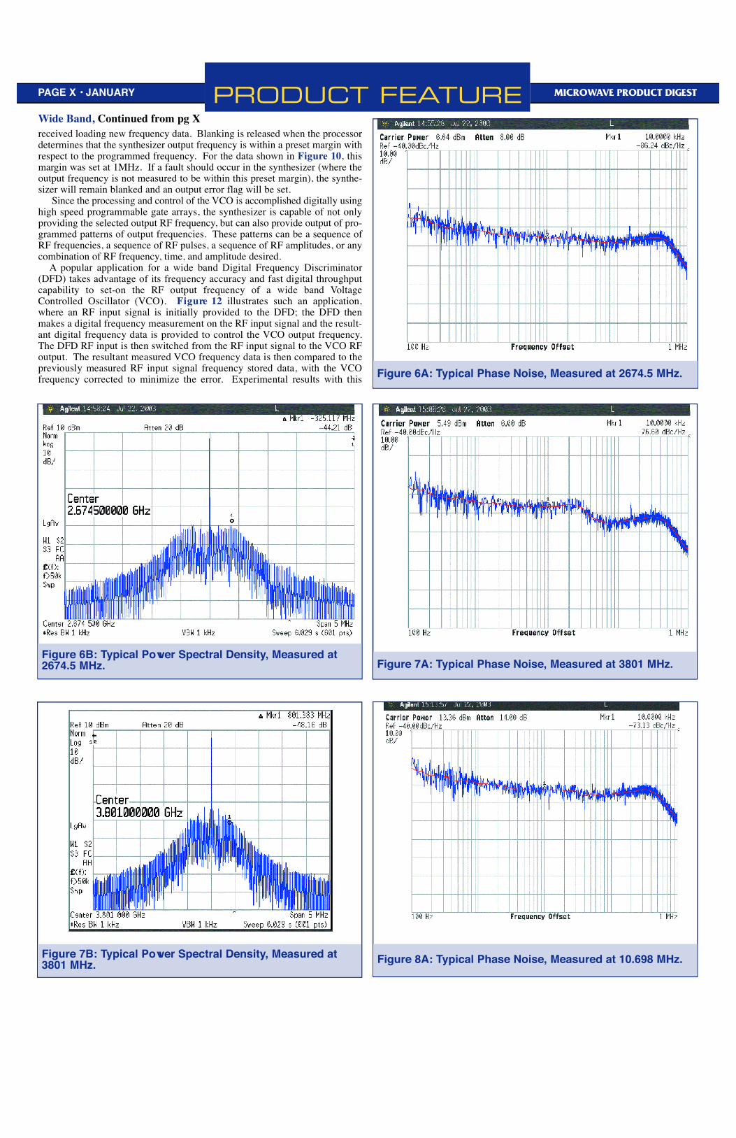
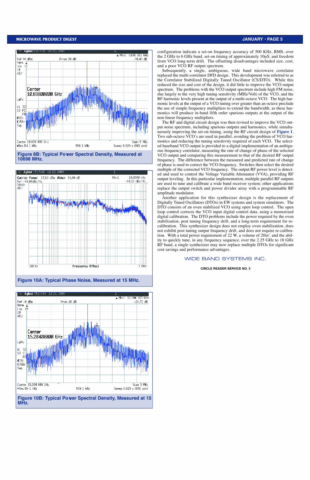
PRODUCT FEATURE PAGE 36 • JANUARY 2004 MICROWAVE PRODUCT DIGEST Miniature Ultra-High Speed Synthesizer Covers 2.25 to 18 GHz for Broad Applications Flexibility by Wide Band Systems, Inc. A new miniature wide band frequency synthesizer that operates from 2.25 GHz to 18 GHz, permits 3μS tuning, exhibits volume of 334.3 cc (20.4in 3 ), consumes just 25W DC power, and provides a clean RF out- put spectrum with an absolute accuracy better than 10 KHz has been introduced by Wide Band Systems, Inc., Receiver Systems Division. The ultra-high switching speed of this new synthesizer (typically 1000 times faster than simi- lar devices), its ability to seamlessly cover an extremely broad bandwidth range, low power draw, and low phase noise characteristics make it ideal for a variety of applications for test equipment, simulator systems, and as local oscil- lators in advanced receiver systems. The new synthesizer (patent pending) represents a new class of microwave frequency synthesizers, according to the company. Its design is based upon wide band frequency locking a voltage controlled oscillator (VCO) to a clock reference. In this configuration, a pair of sub-octave VCOs are doubled and then redoubled to provide single band 2.25 GHz to 18 GHz frequency cover- age, substantially enhancing its versatility and usefulness. The new synthesizer’s small size (only 12.7 x 195 x 135 mm) and low power requirement opens a variety of new applications possibilities, especial- ly when combined with its fast acquisition times and enhanced accuracy. Ultra-high speed switching capabilities permit faster receiver tuner acquisition of emitter signals. The capabilities make the new Wide Band synthesizer ideal for use as a local oscillator (LO) in fast tuning superheterodyne receivers. For this application, the synthesizer provides substantial improvement in tuning times and spurious signal generation, with acceptable phase noise and fre- quency accuracy. The new Wide Band frequency synthesizer is being produced in three differ- ent physical configurations, all of which incorporate a basic circuit design (See Figure 1): The 2U rack chassis illustrated by Figure 2; the replacement syn- thesizer package shown in Figure 3; and, the integrated package of Figure 4. All three designs share the same circuits; the 2U rack chassis was configured to meet a specific installation requirement; the replacement synthesizer package was physically designed to replace a prior phase lock synthesizer design; and the integrated synthesizer configuration is a component of an airborne Radar Warning Receiver (RWR) system. All three designs share the following basic performance characteristics: RF output frequency range: 2.25-18 GHz RF output frequency resolution: 1 MHz (Available frequency resolution is down to 3.9 KHz) Output frequency accuracy: 10 KHz (Figure 5) Harmonic and spurious outputs: -60dBc Phase Noise: Output Frequency @10 KHz Offset @1 MHz Offset Figure 2674.5 MHz: -86 dBc/Hz -96 dBc/Hz 6A 3801.0 MHz: -76 dBc/Hz -95 dBc/Hz 7A 10698 MHz: -73 dBc/Hz -88 dBc/Hz 8A 15204 MHz: -65 dBc/Hz -82 dBc/Hz 9A (Each phase noise graph is provided with the corresponding output power spectral density graph, as Figures 6B, 7B, 8B, and 9B.) Tuning time (Figure 10): Typical 3μS, maximum 7μs Dimensions: 2U Rack synthesizer chassis RETMA 2U rack chassis Replacement synthesizer chassis: 120.90 x 222.25 x 120.65 mm 4.76 x 8.75 x 4.75 in. Integrated synthesizer chassis*: 135 x 195 x 12.7 mm 5.315 x 7.677 x 0.500 in. DC Power: 22 W *Dimensions for the integrated synthesizer chassis do not include the cooling fins. With respect to tuning time, as illustrated in Figure 10, the synthesizer blanks the RF output during an output frequency transition. When a synthesiz- er is employed as a Local Oscillator (LO) in a narrow IF bandwidth tuner, fail- ure to blank the LO when changing the LO frequency may produce an uncon- trolled spurious frequency to appear in the IF filter. The tuner would then have to wait until this spurious filter response dies out; a narrow band IF filter can waste substantial receiver time. Since the synthesizer operates by comparing the current VCO frequency to the input selected RF frequency, the digital pro- cessing automatically blanks the synthesizer RF output as soon as a strobe is Figure 1: Synthesizer RF Circuits Figure 2: Synthesizer 2U Rack Configuration Figure 3: Synthesizer Replacement Configuration Figure 4: Integrated Synthesizer Configuration Figure 5: Measured RF Frequency Accuracy, 2.25 - 18 GHz. Wide Band, Continued on pg X
Transcript
PRODUCT FEATUREPAGE 36 • JANUARY 2004 MICROWAVE PRODUCT DIGEST
Miniature Ultra-High Speed Synthesizer Covers 2.25 to 18 GHz forBroad Applications Flexibilityby Wide Band Systems, Inc.
Anew miniature wide band frequency synthesizer that operates from 2.25GHz to 18 GHz, permits 3µS tuning, exhibits volume of 334.3 cc(20.4in3), consumes just 25W DC power, and provides a clean RF out-
put spectrum with an absolute accuracy better than 10 KHz has been introducedby Wide Band Systems, Inc., Receiver Systems Division. The ultra-highswitching speed of this new synthesizer (typically 1000 times faster than simi-lar devices), its ability to seamlessly cover an extremely broad bandwidthrange, low power draw, and low phase noise characteristics make it ideal for avariety of applications for test equipment, simulator systems, and as local oscil-lators in advanced receiver systems.
The new synthesizer (patent pending) represents a new class of microwavefrequency synthesizers, according to the company. Its design is based uponwide band frequency locking a voltage controlled oscillator (VCO) to a clockreference. In this configuration, a pair of sub-octave VCOs are doubled andthen redoubled to provide single band 2.25 GHz to 18 GHz frequency cover-age, substantially enhancing its versatility and usefulness.
The new synthesizer’s small size (only 12.7 x 195 x 135 mm) and lowpower requirement opens a variety of new applications possibilities, especial-ly when combined with its fast acquisition times and enhanced accuracy.Ultra-high speed switching capabilities permit faster receiver tuner acquisitionof emitter signals. The capabilities make the new Wide Band synthesizer idealfor use as a local oscillator (LO) in fast tuning superheterodyne receivers. Forthis application, the synthesizer provides substantial improvement in tuningtimes and spurious signal generation, with acceptable phase noise and fre-quency accuracy.
The new Wide Band frequency synthesizer is being produced in three differ-ent physical configurations, all of which incorporate a basic circuit design (SeeFigure 1): The 2U rack chassis illustrated by Figure 2; the replacement syn-thesizer package shown in Figure 3; and, the integrated package of Figure 4.All three designs share the same circuits; the 2U rack chassis was configured tomeet a specific installation requirement; the replacement synthesizer packagewas physically designed to replace a prior phase lock synthesizer design; andthe integrated synthesizer configuration is a component of an airborne RadarWarning Receiver (RWR) system.
All three designs share the following basic performance characteristics:
RF output frequency range: 2.25-18 GHzRF output frequency resolution: 1 MHz
(Available frequency resolution is down to 3.9 KHz)
Output frequency accuracy: 10 KHz (Figure 5)Harmonic and spurious outputs: -60dBc
(Each phase noise graph is provided with the corresponding output powerspectral density graph, as Figures 6B, 7B, 8B, and 9B.)
Tuning time (Figure 10): Typical 3µS, maximum 7µs
Dimensions:2U Rack synthesizer chassis RETMA 2U rack chassisReplacement synthesizer chassis: 120.90 x 222.25 x 120.65 mm
4.76 x 8.75 x 4.75 in.Integrated synthesizer chassis*: 135 x 195 x 12.7 mm
5.315 x 7.677 x 0.500 in.DC Power: 22 W*Dimensions for the integrated synthesizer chassis do not include the cooling fins.
With respect to tuning time, as illustrated in Figure 10, the synthesizerblanks the RF output during an output frequency transition. When a synthesiz-er is employed as a Local Oscillator (LO) in a narrow IF bandwidth tuner, fail-ure to blank the LO when changing the LO frequency may produce an uncon-trolled spurious frequency to appear in the IF filter. The tuner would then haveto wait until this spurious filter response dies out; a narrow band IF filter canwaste substantial receiver time. Since the synthesizer operates by comparingthe current VCO frequency to the input selected RF frequency, the digital pro-cessing automatically blanks the synthesizer RF output as soon as a strobe is
PRODUCT FEATUREPAGE X • JANUARY MICROWAVE PRODUCT DIGEST
received loading new frequency data. Blanking is released when the processordetermines that the synthesizer output frequency is within a preset margin withrespect to the programmed frequency. For the data shown in Figure 10, thismargin was set at 1MHz. If a fault should occur in the synthesizer (where theoutput frequency is not measured to be within this preset margin), the synthe-sizer will remain blanked and an output error flag will be set.
Since the processing and control of the VCO is accomplished digitally usinghigh speed programmable gate arrays, the synthesizer is capable of not onlyproviding the selected output RF frequency, but can also provide output of pro-grammed patterns of output frequencies. These patterns can be a sequence ofRF frequencies, a sequence of RF pulses, a sequence of RF amplitudes, or anycombination of RF frequency, time, and amplitude desired.
A popular application for a wide band Digital Frequency Discriminator(DFD) takes advantage of its frequency accuracy and fast digital throughputcapability to set-on the RF output frequency of a wide band Vo l t a g eControlled Oscillator (VCO). F i g u re 12 illustrates such an application,where an RF input signal is initially provided to the DFD; the DFD thenmakes a digital frequency measurement on the RF input signal and the result-ant digital frequency data is provided to control the VCO output frequency.The DFD RF input is then switched from the RF input signal to the VCO RFoutput. The resultant measured VCO frequency data is then compared to thepreviously measured RF input signal frequency stored data, with the V C Ofrequency corrected to minimize the error. Experimental results with this Figure 6A: Typical Phase Noise, Measured at 2674.5 MHz.
Figure 6B: Typical Power Spectral Density, Measured at2674.5 MHz. Figure 7A: Typical Phase Noise, Measured at 3801 MHz.
Wide Band, Continued from pg X
Figure 8A: Typical Phase Noise, Measured at 10.698 MHz.Figure 7B: Typical Power Spectral Density, Measured at3801 MHz.
MICROWAVE PRODUCT DIGEST JANUARY • PAGE 5
Figure 8B: Typical Power Spectral Density, Measured at10698 MHz.
Figure 10A: Typical Phase Noise, Measured at 15 MHz.
Figure 10B: Typical Power Spectral Density, Measured at 15MHz.
configuration indicate a set-on frequency accuracy of 500 KHz, RMS, overthe 2 GHz to 6 GHz band, set-on timing of approximately 10µS, and freedomfrom VCO long-term drift. The offsetting disadvantages included size, cost,and a poor VCO RF output spectrum.
S u b s e q u e n t l y, a single, ambiguous, wide band microwave correlatorreplaced the multi-correlator DFD design. This development was referred to asthe Correlator Stabilized Digitally Tuned Oscillator (CS/DTO). While thisreduced the size and cost of the design, it did little to improve the VCO outputspectrum. The problems with the VCO output spectrum include high FM noise,due largely to the very high tuning sensitivity (MHz/Volt) of the VCO, and theRF harmonic levels present at the output of a multi-octave VCO. The high har-monic levels at the output of a VCO tuning over greater than an octave precludethe use of simple frequency multipliers to extend the bandwidth, as these har-monics will produce in-band fifth order spurious outputs at the output of thenon-linear frequency multipliers.
The RF and digital circuit design was then revised to improve the VCO out-put noise spectrum, including spurious outputs and harmonics, while simulta-neously improving the set-on timing, using the RF circuit design of Figure 1.Two sub-octave VCO’s are used in parallel, avoiding the problem of VCO har-monics and reducing the tuning sensitivity required of each VCO. The select-ed baseband VCO output is provided to a digital implementation of an ambigu-ous frequency correlator, measuring the rate of change of phase of the selectedVCO output and comparing this measurement to that of the desired RF outputfrequency. The difference between the measured and predicted rate of changeof phase is used to correct the VCO frequency. Switches then select the desiredmultiple of the corrected VCO frequency. The output RF power level is detect-ed and used to control the Voltage Variable Attenuator (VVA), providing RFoutput leveling. In this particular implementation, multiple parallel RF outputsare used to tune and calibrate a wide band receiver system; other applicationsreplace the output switch and power divider array with a programmable RFamplitude modulator.
Another application for this synthesizer design is the replacement ofDigitally Tuned Oscillators (DTOs) in EW systems and system simulators. TheDTO consists of an oven stabilized VCO using open loop control. The openloop control corrects the VCO input digital control data, using a memorizeddigital calibration. The DTO problems include the power required by the ovenstabilization, post tuning frequency drift, and a long-term requirement for re-calibration. This synthesizer design does not employ oven stabilization, doesnot exhibit post tuning output frequency drift, and does not require re-calibra-tion. With a total power requirement of 22 W, a volume of 20in3, and the abil-ity to quickly tune, in any frequency sequence, over the 2.25 GHz to 18 GHzRF band, a single synthesizer may now replace multiple DTOs for significantcost savings and performance advantages.