+ All Categories
Home > Documents > Minimizing Corrosion in SRU Vapor Lines … · The heating media was saturated steam at an...

Minimizing Corrosion in SRU Vapor Lines … · The heating media was saturated steam at an...

Date post: 12-May-2018
Category:
Upload: lamquynh
View: 216 times
Download: 0 times
Share this document with a friend
14
Minimizing Corrosion in SRU Vapor Lines David R. Hornbaker (retired) and Thomas C. Willingham, P.E. Controls Southeast, Inc. (CSI) Charlotte, NC, USA Graham MacPherson, P. Eng. Millenia Engineering Calgary, AB, Canada ABSTRACT A very large western Canada gas plant started up in 1992. Within the first year of operation, corrosion failures occurred in large vapor lines, which were steam tube traced. By 1999, many of these lines had to be replaced (they no longer could be patched), and the heating method was changed to ControTrace high-performance steam tracing. During a 2012 maintenance turnaround, some of the vapor lines replaced in 1999 were removed and found to have many years of life remaining. This paper explains the theory and design principles used to accomplish this extensive improvement in unit life. Lessons learned are also included. 1. BACKGROUND 1.1 SRU Vapor Lines Throughout the world, sulphur recovery units (SRUs) in refineries and natural gas plants typically include numerous SRU vapor lines, including tail-gas lines, degas vapor lines, and sweep air lines. All SRU vapor lines containing sulphur should be heated adequately in order to prevent internal condensation of either sulphur vapor or water. Failure to heat these lines properly leads to aggressive corrosion inside the piping. Such corrosion substantially reduces the life of the piping, as in the case of the sweep air lines at a gas processing plant in western Canada.
Transcript

Minimizing Corrosion in SRU Vapor Lines

David R. Hornbaker (retired) and Thomas C. Willingham, P.E.

Controls Southeast, Inc. (CSI)

Charlotte, NC, USA

Graham MacPherson, P. Eng.

Millenia Engineering

Calgary, AB, Canada

ABSTRACT

A very large western Canada gas plant started up in 1992. Within the first year of

operation, corrosion failures occurred in large vapor lines, which were steam tube

traced. By 1999, many of these lines had to be replaced (they no longer could be

patched), and the heating method was changed to ControTrace high-performance steam

tracing. During a 2012 maintenance turnaround, some of the vapor lines replaced in

1999 were removed and found to have many years of life remaining. This paper

explains the theory and design principles used to accomplish this extensive

improvement in unit life. Lessons learned are also included.

1. BACKGROUND

1.1 SRU Vapor Lines

Throughout the world, sulphur recovery units (SRUs) in refineries and natural gas

plants typically include numerous SRU vapor lines, including tail-gas lines, degas vapor

lines, and sweep air lines. All SRU vapor lines containing sulphur should be heated

adequately in order to prevent internal condensation of either sulphur vapor or water.

Failure to heat these lines properly leads to aggressive corrosion inside the piping. Such

corrosion substantially reduces the life of the piping, as in the case of the sweep air lines

at a gas processing plant in western Canada.

Minimizing Corrosion in SRU Vapor Lines

2

1.2 Sweep Air Lines at Canadian Natural Gas Plant

When the Canadian gas plant started up in 1992, the SRU contained piping that

conveyed sweep air from the sulphur pit via an ejector and a blower to the incinerator.

Sweep air line sizes were 20-inch, 24-inch, and 30-inch diameter piping, and each line

ran approximately 55 meters from the sulphur pit to the incinerator. Figure 1 shows a

system isometric drawing of the actual piping system.

Figure 1: System Isometric - Sweep Air Lines

To heat the sweep air lines, the gas plant originally used conventional 5/8-inch tube

tracing, with no heat transfer compound applied between the tracing and pipe. A

representative example of such an installation is shown in Figure 2.

Figure 2: Convective Tube Tracing Installed on Large-Bore Piping

The heating media was saturated steam at an operating pressure of 500 kPag (~160 °C).

The 20- and 24-inch sweep air lines were installed with 10 tracing tubes per line, while

the 30-inch lines were installed with 12 tracing tubes. In horizontal runs, these tracing

Minimizing Corrosion in SRU Vapor Lines

3

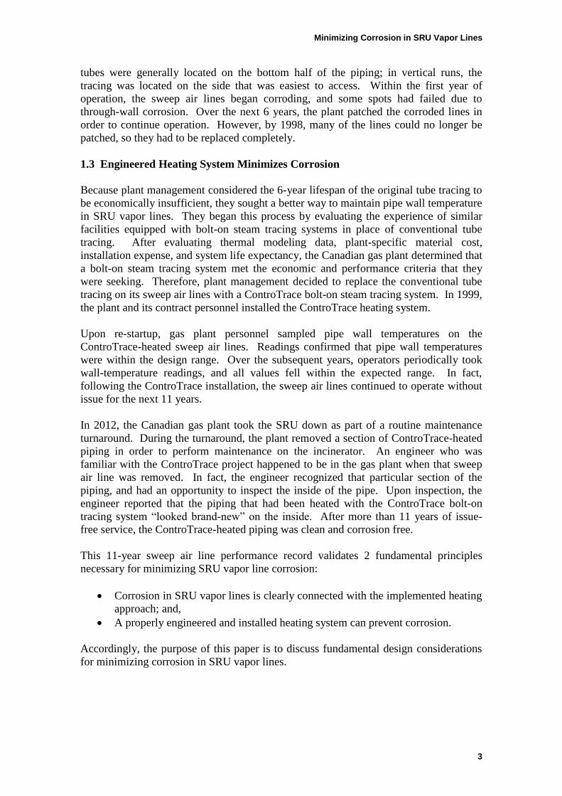
tubes were generally located on the bottom half of the piping; in vertical runs, the

tracing was located on the side that was easiest to access. Within the first year of

operation, the sweep air lines began corroding, and some spots had failed due to

through-wall corrosion. Over the next 6 years, the plant patched the corroded lines in

order to continue operation. However, by 1998, many of the lines could no longer be

patched, so they had to be replaced completely.

1.3 Engineered Heating System Minimizes Corrosion

Because plant management considered the 6-year lifespan of the original tube tracing to

be economically insufficient, they sought a better way to maintain pipe wall temperature

in SRU vapor lines. They began this process by evaluating the experience of similar

facilities equipped with bolt-on steam tracing systems in place of conventional tube

tracing. After evaluating thermal modeling data, plant-specific material cost,

installation expense, and system life expectancy, the Canadian gas plant determined that

a bolt-on steam tracing system met the economic and performance criteria that they

were seeking. Therefore, plant management decided to replace the conventional tube

tracing on its sweep air lines with a ControTrace bolt-on steam tracing system. In 1999,

the plant and its contract personnel installed the ControTrace heating system.

Upon re-startup, gas plant personnel sampled pipe wall temperatures on the

ControTrace-heated sweep air lines. Readings confirmed that pipe wall temperatures

were within the design range. Over the subsequent years, operators periodically took

wall-temperature readings, and all values fell within the expected range. In fact,

following the ControTrace installation, the sweep air lines continued to operate without

issue for the next 11 years.

In 2012, the Canadian gas plant took the SRU down as part of a routine maintenance

turnaround. During the turnaround, the plant removed a section of ControTrace-heated

piping in order to perform maintenance on the incinerator. An engineer who was

familiar with the ControTrace project happened to be in the gas plant when that sweep

air line was removed. In fact, the engineer recognized that particular section of the

piping, and had an opportunity to inspect the inside of the pipe. Upon inspection, the

engineer reported that the piping that had been heated with the ControTrace bolt-on

tracing system “looked brand-new” on the inside. After more than 11 years of issue-

free service, the ControTrace-heated piping was clean and corrosion free.

This 11-year sweep air line performance record validates 2 fundamental principles

necessary for minimizing SRU vapor line corrosion:

Corrosion in SRU vapor lines is clearly connected with the implemented heating

approach; and,

A properly engineered and installed heating system can prevent corrosion.

Accordingly, the purpose of this paper is to discuss fundamental design considerations

for minimizing corrosion in SRU vapor lines.

Minimizing Corrosion in SRU Vapor Lines

4

2. HEATING OBJECTIVE

2.1 Sulphur Vapor Lines

In an SRU, the sweep air system is designed to prevent the concentration of hydrogen

sulfide (H2S) vapor in the head space of sulphur storage equipment (pits, collection

vessels, and tanks) from exceeding explosive limits. Ambient air is pulled through the

storage equipment via a blower or steam ejector to sweep the head space. The sweep air

flow rate is designed to provide enough dilution, based upon expected outgassing rates

of sulphur in the storage equipment. Similar to tail gas lines, sweep air lines contain

sulphur vapor. In the case of the Canadian gas plant’s sulphur pit, air is swept through

the pit by both a blower and a steam ejector, with sweep air flowing to the incinerator

through large-bore piping. In a piping system such as this, the primary heating

objective is to prevent corrosion, as shown in Figure 3, and to prevent plugging, as

shown in Figure 4.

Figure 3: SRU Vapor Line Failure due to Extreme Corrosion

Minimizing Corrosion in SRU Vapor Lines

5

Figure 4: SRU Vapor Line Failure due to Plugging

To prevent corrosion and plugging, some form of heating system—most commonly

tube tracing or ControTrace bolt-on jacketing—must be designed and implemented.

2.2 Heating System Design

The heating system design varies, based upon many conditions, including:

Ambient temperature extremes;

Sweep flow rate;

Ejector motive gas (if used);

Pipe material and thickness;

Insulation type and thickness;

Heating medium (steam or liquid);

Heating medium flow rate;

Complexity of pipe routing; and,

Pipe supports.

Other variables include differences in licensed technology, feedstock chemistry, and

local site operations. Taken together, this variability contributes to a relatively broad

range of industry positions on the actual heating approach. There is certainly not a

single theory of corrosion prevention in SRU vapor lines. Some industry experts are

even willing to allow condensation, provided there is no solidification. Opinions also

Minimizing Corrosion in SRU Vapor Lines

6

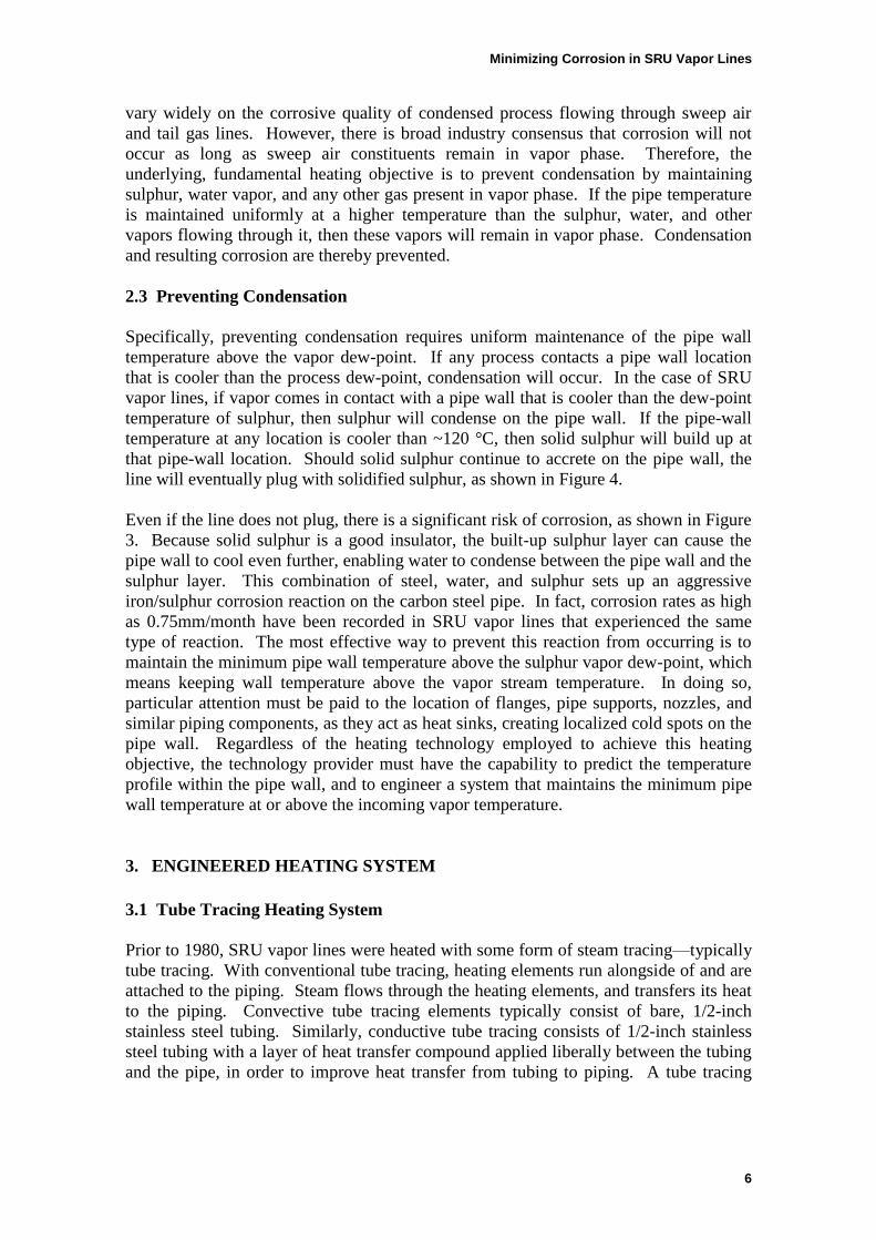
vary widely on the corrosive quality of condensed process flowing through sweep air

and tail gas lines. However, there is broad industry consensus that corrosion will not

occur as long as sweep air constituents remain in vapor phase. Therefore, the

underlying, fundamental heating objective is to prevent condensation by maintaining

sulphur, water vapor, and any other gas present in vapor phase. If the pipe temperature

is maintained uniformly at a higher temperature than the sulphur, water, and other

vapors flowing through it, then these vapors will remain in vapor phase. Condensation

and resulting corrosion are thereby prevented.

2.3 Preventing Condensation

Specifically, preventing condensation requires uniform maintenance of the pipe wall

temperature above the vapor dew-point. If any process contacts a pipe wall location

that is cooler than the process dew-point, condensation will occur. In the case of SRU

vapor lines, if vapor comes in contact with a pipe wall that is cooler than the dew-point

temperature of sulphur, then sulphur will condense on the pipe wall. If the pipe-wall

temperature at any location is cooler than ~120 °C, then solid sulphur will build up at

that pipe-wall location. Should solid sulphur continue to accrete on the pipe wall, the

line will eventually plug with solidified sulphur, as shown in Figure 4.

Even if the line does not plug, there is a significant risk of corrosion, as shown in Figure

3. Because solid sulphur is a good insulator, the built-up sulphur layer can cause the

pipe wall to cool even further, enabling water to condense between the pipe wall and the

sulphur layer. This combination of steel, water, and sulphur sets up an aggressive

iron/sulphur corrosion reaction on the carbon steel pipe. In fact, corrosion rates as high

as 0.75mm/month have been recorded in SRU vapor lines that experienced the same

type of reaction. The most effective way to prevent this reaction from occurring is to

maintain the minimum pipe wall temperature above the sulphur vapor dew-point, which

means keeping wall temperature above the vapor stream temperature. In doing so,

particular attention must be paid to the location of flanges, pipe supports, nozzles, and

similar piping components, as they act as heat sinks, creating localized cold spots on the

pipe wall. Regardless of the heating technology employed to achieve this heating

objective, the technology provider must have the capability to predict the temperature

profile within the pipe wall, and to engineer a system that maintains the minimum pipe

wall temperature at or above the incoming vapor temperature.

3. ENGINEERED HEATING SYSTEM

3.1 Tube Tracing Heating System

Prior to 1980, SRU vapor lines were heated with some form of steam tracing—typically

tube tracing. With conventional tube tracing, heating elements run alongside of and are

attached to the piping. Steam flows through the heating elements, and transfers its heat

to the piping. Convective tube tracing elements typically consist of bare, 1/2-inch

stainless steel tubing. Similarly, conductive tube tracing consists of 1/2-inch stainless

steel tubing with a layer of heat transfer compound applied liberally between the tubing

and the pipe, in order to improve heat transfer from tubing to piping. A tube tracing

Minimizing Corrosion in SRU Vapor Lines

7

approach is based on the premise that the heating objective is simply to add more heat to

the pipe than the pipe loses.

3.2 ControTrace Engineered Heating System

In 1980, an engineered heating system known as ControTrace was introduced.

ControTrace heating elements are drawn from carbon steel, SA-178 boiler tubes into a

rectangular shape. One side of the ControTrace heating element is curved, in order to

fit tightly against the outside contour of the pipe. Steam flows through the heating

element and transfers its heat to the pipe. Heat exchange between the steam and the

pipe is enhanced greatly by applying a thin film of heat transfer compound between the

curved side of the ControTrace element and the outside contour of the pipe. When

heating vapor lines with ControTrace, the heating objective is to maintain pipe wall

temperature above the vapor dew-point at all points on the pipe wall.

3.3 Performance Advantages of ControTrace Versus Tube Tracing

These physical characteristics give ControTrace 4 distinct performance advantages over

conventional tube tracing. First, ControTrace has a much broader heat transfer contact

area. Unlike the point-to-point contact of tube tracing, ControTrace has a 50mm-wide

heating element, with contoured geometry to fit piping. Second, ControTrace also has

more reliable heat transfer efficiency. Because of the consistent distance between

tracing and piping, an optimal thickness of non-hardening heat transfer compound can

be applied. Third, ControTrace heating systems employ an engineered sizing approach.

When designing a ControTrace system, engineers utilize a finite-difference heat transfer

model, as opposed to rule-of-thumb calculations. The finite-difference model calculates

the exact number and placement of elements required to maintain the pipe wall

temperature above the process temperature at every point on the pipe wall. Spacing of

the heating elements is critical, because the pipe wall temperatures are lowest at the

midpoint between elements. If the heating elements are spaced too far apart, then the

midpoint temperature can be lower than the vapor stream temperature, resulting in

condensation and subsequent plugging and corrosion. For this reason, ControTrace is

manufactured in panels, as shown in Figure 5. These panels naturally maintain the

proper element spacing when installed. Fourth, the ControTrace panels are engineered

specifically to fit the line for which they are designed; therefore, no field modification

or fabrication is required. Tube tracing, on the other hand, cannot be paneled, which

places the entire responsibility for maintaining proper element spacing on the installer.

This spacing is critical to maintaining an adequate pipe wall temperature at all points.

Minimizing Corrosion in SRU Vapor Lines

8

Figure 5: ControTrace Panels Installed on Large SRU Vapor Piping

3.4 Thermal Analysis of Original Heating System

In 1999, when the Canadian gas plant decided to replace its original tube tracing system

with the ControTrace engineered heating system, the first step was to conduct a detailed

thermal analysis of the original tube tracing system. Most tube tracing programs only

consider the pipe size, temperature, insulation, and ambient conditions. Using these

factors, tube tracing programs calculate total heat loss from the pipe. The total heat loss

calculation determines the number of heating elements needed to replace the lost heat.

However, no consideration is given to how that heat replacement gets distributed to all

parts of the pipe. Simply adding more heat than the piping is losing does not ensure that

all points on the pipe are above the condensation temperature. Accordingly, the detailed

thermal analysis confirmed that the 12-element coverage of the original tube tracing

system would lead to inadequate heating at the midpoint between the elements, as

evident in the finite-element computer model in Figure 6. All points on the pipe should

be at or above 130 °C, the calculated temperature of the incoming vapor stream. Yet, as

the model clearly shows, the pipe wall is below 130 °C at the midpoint between each

tube tracing element.

Minimizing Corrosion in SRU Vapor Lines

9

Figure 6: Finite-Element Model Depicting 12 Tube Tracing Elements Evenly Spaced around the Pipe

To compound this problem, the original tube tracing system was not installed with

perfectly even spacing between the elements. In fact, the original tube tracing was

installed on the bottom half of the piping on horizontal piping runs; and on vertical runs,

the tube tracing was installed on the pipe half that was most convenient to access, as

shown in Figure 7. As the model indicates, the unheated half of the pipe was even

colder than the minimum wall temperature in the evenly spaced configuration.

Figure 7: Finite-Element Model Depicting 12 Tube Tracing Elements As Installed on Half of the Pipe

Minimizing Corrosion in SRU Vapor Lines

10

Whether the tubing is clustered on half of the pipe or evenly spaced around the entire

circumference, the model points to the same outcome: many points on the pipe wall are

inadequately heated, resulting in condensation and subsequent corrosion. Actual

performance of the original system validated this finding, as the sweep air piping began

corroding in the first year of operation with the tube tracing system. Thus, the thermal

analysis and actual performance clearly confirmed that the number of tube tracing

elements and their spacing around the pipe were insufficient to deliver the pipe wall

temperatures necessary to prevent condensation and corrosion.

3.5 Thermal Analysis of ControTrace Heating System

In redesigning the heating system with ControTrace, the supplier’s engineers used the

same finite-difference computer model to analyze all the factors involved in heating and

cooling the pipe. A model of vapor flow through the pipe was developed, using the

following data sets:

Pipe size;

Wall thickness and material properties;

Insulation thickness and properties;

Worst-case ambient conditions;

Wind conditions;

Process gas properties; and,

Flow rates.

With these inputs, the model generated temperature profiles of the piping system under

various operating conditions. Specifically, the model determined how much heat was

entering the pipe. It also calculated how that heat was distributed by conduction along

the pipe wall and through the insulation, and by convection to the process itself. By

applying the finite-difference computer model, the model provider determined the

optimum number of ControTrace heating elements and their placement on the pipe. As

shown in Figure 8, the model output indicated that 4 ControTrace elements, evenly

spaced around the pipe, would deliver the minimum pipe wall temperatures required to

prevent process condensation.

Minimizing Corrosion in SRU Vapor Lines

11

Figure 8: Finite-Element Model for Engineered ControTrace System

While engineering the heating system for the Canadian gas plant, it was also critical to

account for flanges and supports. From a heat-transfer perspective, flanges and pipe

supports act as heat sinks. At the points where they contact the piping, flanges and pipe

supports create localized cold spots, inevitably resulting in condensation and subsequent

corrosion. Accordingly, the heating system design included flange jacketing rings to

compensate for cold spots at the flange pairs. Thermal modeling demonstrated that a

ControTrace ring on each flange would completely neutralize the heat-sink effect of that

flange. Similarly, thermal modeling indicated the number and configuration of

ControTrace elements needed to heat each pipe support. Figure 9 shows a typical

example of an unheated pipe support attached to a properly heated pipe. In contrast,

Figure 10 shows a heated pipe support attached to a properly heated pipe. Accounting

for the pipe supports and flanges ensured that the engineered heating system would not

encounter any localized cold spots, as depicted in Figure 9, thereby preventing

condensation and resulting corrosion.

Minimizing Corrosion in SRU Vapor Lines

12

Figure 9: Finite-Difference Model for an Unheated Pipe Support Attached to a Properly Heated Pipe

Figure 10: Finite-Difference Model for a Heated Pipe Support Attached to a Properly Heated Pipe

3.6 Eleven-Year Performance Evaluation

After evaluating all thermal modeling, the manufacturer designed and fabricated the

rings and headered panels that comprised the new ControTrace heating system. In

Minimizing Corrosion in SRU Vapor Lines

13

1999, the Canadian gas plant and its contract personnel installed the heating system.

Upon startup, they measured pipe wall temperatures, and the readings at all points

revealed temperatures above the inlet vapor process temperature. Periodic readings in

subsequent years indicated that the ControTrace system continued to maintain pipe wall

temperatures in the designed range, thereby preventing condensation and corrosion.

The gas plant operated the sweep air lines and ControTrace heating system for over 11

years without any issues. ControTrace system performance was positively confirmed

during a 2012 maintenance turnaround, when one of the sweep air lines was removed

and found to have many years of life remaining.

4. LESSONS LEARNED

4.1 Corrosion is Directly Related to Heating Approach

First, corrosion in SRU vapor lines is clearly connected with the heating approach. A

properly engineered and installed heating system can prevent corrosion. Years of

successful ControTrace performance in this particular gas plant, contrasted with poor

tube tracing performance, prove this fact. With an inadequately designed heating

system, the vapor lines did not even last 1 year without significant corrosion. Yet with a

ControTrace heating system installed, the sweep air lines performed without issue for

over 11 years leading up to the 2012 maintenance turnaround; and they were put back in

service with many more years of service life remaining. Even further proof lies in the

finite-difference models, which clearly demonstrate the ineffectiveness of a rule-of-

thumb heating system, contrasted with the effectiveness of an engineered heating

system in preventing corrosion.

4.2 Sweep Air Temperature Is Often Lower Than Assumed

Since 1999, experience has proven that the temperature of sweep air exiting a pit is

lower than most operators typically estimate. Judging from data sheets submitted for

sweep air lines, many operators assume that the sweep air exits the sulphur pit at

roughly the same temperature as the liquid sulphur in the pit (130-140 °C). However,

actual modeling indicates that sweep air exits the pit at a much lower temperature, in the

range of 65-85 °C. The reason for this is the sweep air system draws in ambient air and

pulls it across the head space of the pit. Depending on flow rate and pit size, sweep air

can be drawn across the head space in less than a minute. With such a short residence

time in the pit head space, the sweep air simply does not remain there long enough to

reach equilibrium temperature with the liquid sulphur in the pit. In fact, the sweep air

temperature typically does not even approach the liquid sulphur temperature, and

thermal modeling calculations confirm this phenomenon. Therefore, it is critical to

perform thermal modeling to calculate sweep air exit temperature, rather than relying

solely on assumptions.

4.3 Steam Systems Must Be Properly Routed for Performance

In 1999, it was CSI’s standard practice to provide installation drawings showing the

location of its ControTrace components. At that time, however, CSI left it up to plant

operations or maintenance to determine steam routing through the system. Since then,

Minimizing Corrosion in SRU Vapor Lines

14

CSI has recognized that steam systems are not always well understood in the field.

When routing a steam system, it is important to realize that steam loses pressure as it

travels through circuitry. Because pressure and temperature are directly related,

pressure loss results in temperature loss. Consequently, steam must be re-supplied at

proper intervals, before it loses too much heat to accomplish the given heating

objective. CSI recognizes the need to predict pressure loss reliably in order to properly

design the heating system. CSI also understands the need to design a clear path for

condensate removal. As a result, CSI’s standard practice today goes beyond simply

providing installation drawings. Into every ControTrace heating system, CSI also

designs placement of heating elements, as well as interconnection and location of steam

supplies and condensate returns. Simply stated, correctly routing the steam circuit

ensures proper performance of the heating system; whereas, leaving the steam routing

up to field discretion can result in a heating system that does not perform at all.

4.4 Engineered Systems Can Provide Superior Performance with Lower Costs

When conventional tube tracing is used, it is often chosen because of its perceived low

material cost. However, these decisions seldom account for the cost of the necessary

steam infrastructure, such as valves, steam and condensate manifolds, an adequate

number of steam traps, and enough pre-insulated tubing to connect the steam manifolds

to the tube tracing. As a percentage of total installed costs, steam infrastructure costs

increase with pipe size. Looking at a typical example, the steam infrastructure costs on

a 30-inch SRU vapor line are approximately 50 percent of the total installed costs. This

excludes the cost of replacement due to poor performance of the heating system. In

choosing a pipe heating system, therefore, it is critical to compare the total installed cost

of the proposed systems. In most cases, an engineered system can provide superior

performance with lower overall costs.

5. SUMMARY

When the Canadian gas plant temporarily removed a section of its sweep air piping

during a 2012 maintenance turnaround, CSI was afforded a unique opportunity to

evaluate the long-term performance of its ControTrace heating system. In doing so, CSI

learned that the heating system it engineered in 1999 increased plant life by at least 11

times more than the prior system. CSI also validated 2 important principles for heating

SRU vapor lines:

Corrosion is directly related to heating approach; and

Sweep air temperature must be calculated.

Since this experience with the Canadian gas plant, other projects have shown that steam

systems must be routed properly to ensure heating performance; and, engineered

systems can provide superior performance with lower costs. Today, CSI continues to

apply these principles, and engineer ControTrace heating systems with ever-increasing

sophistication.


Recommended