Special print from “3R international 40 (2001) Special Plastics Pipes”, pages 4-12 VULKAN-VERLAG · HUYSSENALLEE 52-56 · 45128 ESSEN Minimum service-life of buried polyethylene pipes without sand-embedding Dr.-Ing. Joachim Hessel Hessel Ingenieurtechnik GmbH, Roetgen
Transcript
Special print from “3R international 40 (2001) Special Plastics Pipes”, pages 4-12
V U L K A N - V E R L A G · H U Y S S E N A L L E E 5 2 - 5 6 · 4 5 1 2 8 E S S E N
Minimum service-life of buried polyethylene pipeswithout sand-embedding
Dr.-Ing. Joachim Hessel Hessel Ingenieurtechnik GmbH, Roetgen
2
3
In the past 20 years polyethylene raw ma-terials have been developed with the aimof improving the creep rupture strength.This has raised the question whether it ispossible to eliminate sand-embedding ofburied pipes.
Investigations were performed in order todetermine the minimum quality of poly-ethylene pipes for this situation. Thetesting conditions cover the loads whichare to be expected in service. Typical fai-lure histories, the test design and the ma-terial related test conditions in order togenerate a conservative result are descri-bed. The test results of pipes under inter-nal pressure and additional external pointload are reported over a range of test pa-rameters.
A strong correlation between the longterm performance of point loaded pres-sure pipes and the resistance of the ma-terials against slow crack growth as de-termined in Full Notch Creep tests(FNCT) is confirmed. The results from theFNCT are used to predict the minimumservice-life of polyethylene pipes withoutsand-embedding. The calculation is ba-sed on the conservative results of eachtest series.
Four raw material suppliers and threepipe producers were involved in these in-vestigations.
IntroductionIn the past the service-life of buried pipeshas been shown to be reduced due tostress concentrations caused by externalpoint loads. The service-life of the pipesis closely related to the material‘s resis-tance against slow crack growth. Poly-ethylene resins are continuously beingdeveloped with the aim of increasingcreep rupture strength. This increase canbe seen in the creep rupture curves ofvarious standards between 1976 and2000 (e.g. DIN 8075). However, in realitymany of the current resins have creeprupture values significantly higher thanthe minimum requirements.
This raises the question, whether thecreep rupture strength of current resinshas reached a state of developmentwhere a failure of pressure pipes with ad-ditional external point loads should notbe expected during their service-life.
The following companies took part inthese investigations:
Service ExperienceBuried polyethylene pipes can bedamaged by point or linear loadswhich are acting in addition tothe design loads (e.g. internalpressure, earth and traffic load).Linear loads can for example beproduced by wood usedas supports below thepipe during installationand not removed beforethe trench was backfilled[9].
Relevant standards do-cument that a reductionof service-life can resultfrom external point or li-near loads on pipes. Forthis reason, DIN 4033 andDIN 19630 require thatpoint or linear loads onthe external wall of thepipe are to be avoidedduring installation. Forthe same reason, DIN
1046 requires that the trench base mustbe free from stones and rocks.
Typical failures of pressure pipes causedby external, locally concentrated loadsare shown in fig. 1 and 2. The additionalload shown in figure 1 was generated bya piece of rock that continuously pressedagainst the outside of the pipe. The pointof indentation is visible near the crack inthe external pipe wall. The cause for thecrack shown in figure 2 was probably asmall load on a limited area. The fracturesurface of this crack is shown in fig 3.
The starting point of the crack is locatedat the inside of the pipe wall (bottom) andtravels to the outside (top). The fracturesurface shows very low deformationswhich is typical for creep rupture failure.The creep rupture failure is caused bothby the internal pressure and the additio-nal load generated by an object pressingagainst the external pipe wall.
Such failures would not occur if the creeprupture strength at the inside of the pipewall is above the overall local stress atthis point.
Test MaterialsPolyethylene pipes 110 x 10 mm (SDR11) classified as PE 63, PE 80, PE 100
Minimum service-life of buried polyethylene pipeswithout sand-embedding
Dr.-Ing. Joachim HesselHessel Ingenieurtechnik GmbH, Roetgen (D)
Fig. 1: Indentation and associated crack path on theoutside wall of a polyethylene pipe
Fig. 3: Fracture surface in the wall of an externally loaded polyethylene pipe
Fig. 2: Externally loaded area and associated crackpath on the outside wall of a polyethylene pipe
4
according to DIN 8075 as well as cross-linked polyethylene pipes (PE-Xa; PE-Xb)were used for the investigations (table 1).
Table 1: Pipe samples tested
1 s.a. Table 2, 2 ISO/TR 9080, 3 ISO 527 (Tensile load)4 ISO 178 (Bending load)
Table 2: Test program
Principle and Limiting Conditionsof the TestsFNCT
The resistance against slow crack growthof the samples was tested using the FullNotch Creep Test (FNCT) according toDIN EN 12814-3 Annex A. This test me-thod is also described in supplementarysheet 2 of guideline DVS 2203 part 4 andin ISO-draft: ISO/DIS16770: Plastics –Determination of environmental stresscracking (ESC) of polyethylene (PE) –Full–notch creeptest (FNCT).
The test speci-mens were cutfrom the pipes inthe axial directionwith parallel sidesand approximatelysquare cross-sec-tions. Each speci-men was notchedperpendicular tothe parallel lengthin the middle ofthe test specimen.
The specimenswere loaded by aconstant tensile
Fig. 4: Creep rupture times of specimens from pipes of different resistances against slow crack growth in FNCT
stress of 4 N/mm2 ± 0.03 N/mm2 relatingto the remaining unnotched cross-sec-tions. The nominal test temperature was80 °C ± 0.2 K.
The tensile creep tests were performedon 3 test specimens per temperatureusing an aqueous solutions of ®ARKO-PAL N-100 in demineralised water(2/100, w/w) to accelerate the tests.
The FNCT failure times for 13 out of the19 pipes are shown in fig. 4.
External Point Load
The maximum stress that thepipe material will experiencefrom a point load is the yieldstress. Therefore in this test itwas ensured that the displa-cement of the point load intothe pipe wall was sufficient tocause yielding of the materialat the inside of the pipe.
Since the additional stress inthe pipe wall far from thepoint of load will be zero allpossible stresses that mightoccur in the field due to apoint load are represented inthis test.
There are two scenarioswhich are not covered: 1) thepenetration of a sharp object– e.g. a nail – through the pipewall and 2) the completecrushing of the pipe, e.g. by alarge rock. In the last case thepipe is no longer functioning,but the force on the pipe iscomparable to the test load inthe point loading test.
The required surface elon-gation at the inner pipe wall(i.e. the above yield elongati-on) was produced by the dis-placement of a tool along theradius of the pipe with a tool
tip radius of 5 mm. The tool loading wascarried out at room temperature with nointernal pressure in the pipe. The toolwas loaded until a chord with a length of5 mm was measured at the inside surfa-ce of the pipe (fig. 5). This occured at atool displacement of 9 mm from the outersurface of the pipe.
The elongation at the inside surface canbe calculated using the following equa-tion:
ε = [0.318 · F · R] / [b‘ · s · E(t)]
where:
ε Elongation at the inner surface of thepipe wall
F Radial acting force (single load)R Mean pipe radiuss Wall thicknessE(t) E-modulusb‘ Supporting width
The supporting width of the load (b') canbe determined experimentally by measu-ring the force on the tool with the pipeunder internal pressure.
Finite element calculations (fig. 6) con-firm that with the tool loading a pipe un-der internal pressure of 8 bar the elonga-tion of the inner surface of the pipe dueto the tool displacement was in excess oftwice the yield elongation of the material,which is 9 % for all the materials given intable 1.
The internal pressure of the pipes waschosen to produce a hoop stress of 4N/mm2 during the test (ISO 1167).
To accelerate the tests they were perfor-med using an aqueous solution of 2 %Arkopal N-100 and demineralised water.
The test fluid was continuously mixed inthe pipes to prevent separation.
Test materials 1 and 3 were also testedusing water with no detergent.
In order to determine the influence of in-ternal pressure 4 pressure levels wereapplied for test series no. 3. The magni-tude of the additional external point loadwas kept constant.
Test Temperatures
The tests were performed at 80 °C. In ad-dition the activation energy was calcula-ted for test series 1 and 3 by performingtests at temperatures between 20 and 95 °C.
A summary of the test program is givenin table 2.
Theoretical Basis for Determiningthe Maximum Service-LifeGenerally the maximum service-life ofplastics is determined by thermal ageing,which causes embrittlement of the mate-rial. The relevant parameters other thantemperature and time are the environ-ment and the available oxygen.
Water saturated with oxygen has provedto have the greatest effect on the reduc-tion of the maximum service-life becauseit causes accelerated thermal ageing.
Equivalent thermal ageing times are found for either the mixture of a deter-gent and water or just water without adetergent. The time to the beginning ofthe effect of thermal ageing is indepen-dent of the elongation of the material.
The onset of thermal ageing was investi-gated by Gaube et al. in the temperaturerange between 80 °C and 40 °C. The cri-teria for evaluation was that the elongati-on to rupture of the aged sample was 50% of the elongation to rupture of the una-ged sample. Later investigations on pipes under internal pressure showedthat the onset of thermal ageing found byGaube testing sheets was identical withthe starting point of the sharp decent ofthe creep rupture curves of pipes. This
point is the beginning of thermal degra-dation of the pipe [12].
Another method to describe the thermalageing of polyolefines is the measure-ment of the viscosity number accordingto ISO 1628-3. This number is related tothe molecular weight. [13].
With all three methods a correlation isobtained which can be described by theequation of Arrhenius. This means thatthe thermal degradation takes place aftera short period of time at high tempera-tures (e. g. 80 °C) and after a long periodof time at low temperatures (e. g. 20 °C)according to the activation energy.
It is accepted that if polyethylene withconventional stabilisation is tested forone year at 80 °C without thermal ageingthis is equivalent at 20 °C to 100 yearsservice [14].
Results of the InvestigationsAlthough 6 of the 19 test series are notyet completed it is possible to evaluatethe results with regard to the required mi-nimum quality of polyethylene pipes fortheir installation without sand-embed-ding.
Taking into account the evaluation proce-dure [15] the results are conservative,that means they are on the safe side.
Failure MechanismAssuming that the process of slow crackgrowth (stress cracking) is the relevantlong term failure mode for pipes underadditional external point load these re-
5
Fig. 5: Loading by an external point load before starting the internal pressure test
Fig. 6: Surface elongation in % at the insidewall of the pipe due to an external point loadand an internal pressure of 8 bar
Fig. 7: Fracture surface of a FNCT specimentaken from a PE 100 pipe
Fig. 8: Fracture surface in a PE-pipe subjected to an external point load and internal pressure
sults should correlate with the resistanceagainst stress cracking as tested by theFNCT.
The fracture surface both in FNCT (fig. 7)and in the pipe under external point load(fig. 8) shows low deformations withoutevidence of macroscopic ductility. Thishas been confirmed by investigations ofLaurent using a scanning electronmicroscope [16].
The same appearance is also visible atfracture surfaces of pipes under internalpressure only (fig. 9).
For pipes under external point load thecrack always starts at the inside of thepipe wall but not at the point of the lar-gest material strain, directly below theloading tool (fig. 10 to 13). From fig. 6 itcan be assumed that the crack starts inthe region where the material is at the
yield point, i.e. before it becomesoriented.
A similar phenomenon is found inthe Cone-test where the crack initiation is not at the point of ma-ximum elongation but a certaindistance away [17].
Influencing ParametersPipe Quality
The results of the investigationson point loaded pipes and in theFNCT, which are complete at thetime of reporting are shown in
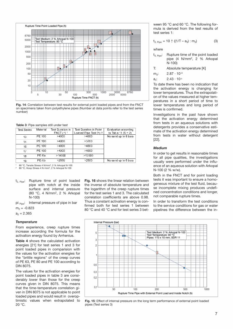
fig. 14, where the figures at the datapoints correspond to the number of thetest series in table 2.
This shows that the pipe quality with re-gard to the long term performance underinternal pressure and additional externalpoint load correlates with the rupture ti-mes of notched specimens in FNCT. Thisrelationship is supported by the correlati-on between pipes under internal pressu-re and FNCT published by Fleißner [18].
As expected the samples made from PE63 show the shortest rupture times bothfor point loaded pipes and in the FNCT.The rupture times in both tests increasefrom PE 80 to PE 100 to PE-X.
Test series no. 4 (PE 80) is exceptionalbecause the rupture times are in the region of some PE 100 materials (no. 6 to 10).
As can be seen in fig. 14 the relationshipbetween the rupture times of the twotests is linear on a double logarithmicscale. The correlation coefficient is grea-ter than 0.98 which is acceptable fortechnical applications. The mathematicaldescription of the correlation leads to theformula:
t1, FNCT = 10 ↑ (m1 · log t1, Pipe + a1) (1)
where
t1, FNCT: Rupture time in FNCT (80 °C, 4 N/mm2, 2 % Arkopal N-100)
t1, Pipe: Rupture time of point loadedpipe and internal pressure (80 °C, 4 N/mm2, 2 % Arkopal N-100)
m1 = 0.874
a1 = -0.151
The shaded area in fig. 14 shows the re-gions where thermal ageing will occur forconventionally stabilised polyethylenepipe resins.
From these results it can be concludedthat pipes with rupture times in the FNCTabove 2000 hours (80 °C, 2 % Arkopal N-100, 4 N/mm2) could be installed withoutsand- embedding for service pressure 4bar (safety factor 2). This is because thepipes under external point load exceedthe limit of thermal ageing at 80 °C,which relates to a service-life of at least100 years at 20 °C [19].
The results of test series no. 12 (pipe un-der external point load) and no. 15 (FNCTand pipe under external point load) canbe found in the area of thermal ageing.
Those test series which are not yet com-pleted at the time of this report are sum-marised in table 3.
Internal Pressure of Pipe
All point loaded pipes were tested withan internal pressure of approximately 8bar following the relevant test standardsfor polyolefin pipes (hoop stress 4N/mm2). For test series no. 3 additionaltests were carried out at lower internalpressures with a notch at the inside pipesurface in line with the point load (fig. 15).
A linear relation in a double logarithmicscale results from these tests in a similarmanner to conventional creep rupturecurves without additional loads. Thisshows that an important influence on thefailure times is the internal pressure in thepipe.
The mathematical description of this re-lation is given in formula 2:
t2, Pipe = 10 ↑ (m2 · log pi Pipe + a2) (2)
where:
6
Fig. 9: Fracture surface in a PE-Pipe subjected to internal pressure only
Fig. 10: Cracks in the inside wall of a PE 80pipe subjected to an external point load andinternal pressure (Test series 4)
Fig. 11: Cracks at the inside wall of a PE 100pipe subjected to an external point load andinternal pressure (Test series 8)
Fig. 12: Cracks at the inside wall of a PE 100pipe subjected to an external point load andinternal pressure (Test series 6)
Fig. 13: Cracks at the inside wall of a PE 100subjected to an external point load and inter-nal pressure (Test series 7)
t2, Pipe: Rupture time of point loadedpipe with notch at the inside surface and internal pressure (80 °C, 4 N/mm2, 2 % Arkopal N-100)
pi Pipe: Internal pressure of pipe in bar
m2 = -0.823
a2 = 2.365
Temperature
From experience, creep rupture times increase according the formula for theactivation energy found by Arrhenius.
Table 4 shows the calculated activationenergies [21] for test series 1 and 3 forpoint loaded pipes in comparision withthe values for the activation energies forthe "brittle regions" of the creep curvesof PE 63, PE 80 and PE 100 according toDIN 8075.
The values for the activation energies forpoint loaded pipes in table 3 are consi-derably lower than those for the creepcurves given in DIN 8075. This meansthat the time-temperature correlation gi-ven in DIN 8075 is not applicable to pointloaded pipes and would result in overop-timistic values when extrapolated to 20 °C.
Fig. 16 shows the linear relation betweenthe inverse of absolute temperature andthe logarithm of the creep rupture timesfor the test series 1 and 3. The calculatedcorrelation coefficients are above 0.98.Thus a constant activation energy is con-firmed both for test series 1 between 80 °C and 40 °C and for test series 3 bet-
ween 95 °C and 60 °C. The following for-mula is derived from the test results oftest series 1:
t3, Pipe = 10 ↑ ((1/T – a3) : m3) (3)
where
t3, Pipe: Rupture time of the point loadedpipe (4 N/mm2, 2 % Arkopal N-100)
T: Absolute temperature [K]
m3: 2.87 · 10-4
a3: 2.43 · 10-3
To date there has been no indication thatthe activation energy is changing for lower temperatures. Thus the extrapolati-on of the values measured at higher tem-peratures in a short period of time to lower temperatures and long period of times is confirmed.
Investigations in the past have shownthat the activation energy determinedfrom tests in an aqueous solutions withdetergents provides a conservative esti-mate of the activation energy determinedfrom tests in water without detergent[22].
Medium
In order to get results in reasonable timesfor all pipe qualities, the investigationsusually were performed under the influ-ence of an aqueous solution with ArkopalN-100 (2 % w/w).
Both in the FNCT and for point loadingtests it was important to ensure a homo-geneous mixture of the test fluid, becau-se incomplete mixing produces undefi-ned concentration conditions and longer,not comparable rupture times.
In order to transform the test conditionsto the service conditions for gas or waterpipelines the difference between the in-
7
Fig. 14: Correlation between test results for external point loaded pipes and from the FNCT on specimens taken from polyethylene pipes (Number at data points refer to the test seriesnumber)
Fig. 15: Effect of internal pressure on the long term performance of external point loaded pipes (Test series 3)
Table 3: Pipe samples still under test
1 80 °C, Tensile Stress 4 N/mm2, 2 % Arkopal N-1002 80 °C, Hoop Stress 4 N /mm2, 2 % Arkopal N-100
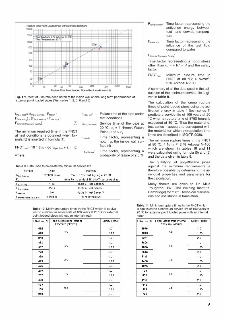
t4, Pipe: Rupture time of the point loadedpipe (80 °C, 4 N/mm2, 2 % Arko-pal N-100)
t4, Notch: Rupture time of the point loadedpipe with an inside notch (80 °C,4 N/mm2, 2 % Arkopal N-100)
m4 = 0.818
a4 = -0.05
These results show that the internal notches reduce the rupture times of apipe which reaches the thermal ageingunder the influence of water by a factorof 4.1 compared to unnotched pipes.
The depth of the notches were variedbetween 0.25 and 0.85 mm using speci-mens from test series 3. However, no sig-nificant difference was found in the creeprupture times.
Scattering of the Test Results
The scattering of the results of test series2, 6 and 9 are given in table 8 and wereused to calculate the cumulative fre-quency at which 2.5 % of the specimenstested would be expected to fail, in a si-milar manner to that used for creeprupture tests (ISO/TR 9080).
Calculation of Minimum Test RequirementsIn order to calculate the minimum test re-quirements equivalent to a specified ser-vice-life of point loaded polyethylene pi-pes at 20 °C applied for water or gasconveyance the following formula isused:
fluences of detergent or water on thecreep rupture behaviour needs to bequantified.
The test data available at the time of thisreport are summarised in table 5. The va-lues agree well with the results from a round robin test on the FNCT [23].
Radius of the Loading Tool
The outside of the pipes were usually loaded using a tool with a tip radius of 5mm. Additional tests were performed ontest series 3 with tool tip radius of 2.5mm and 10 mm.
The test results show that a tool tip radius between 2.5 mm and 10 mm thereis no difference in the rupture times of thepipes (table 6).
Displacement of the Loading Tool
A displacement of the loading tool of 9mm caused an elongation at the inner
surface of the pipe wallwhich exceeded theyield strain of the materi-als.
The displacement of theloading tool was variedbetween 9 mm and 0mm (contact of the loa-ding tool at the outerpipe surface) in test se-ries 3.
In this connection it isimportant to note thatthe pipes were loaded atroom temperature with-out internal pressure butthe tests are carried outat elevated temperaturewith internal pressure.
The results are given intable 7 and indicate there is no signifi-cant difference in rupture times for dis-placements between 0 and 9 mm.
Thus it seems that small displacementsof an external point load introduce a re-duction of the creep rupture time.
Notches at the Inner Pipe Wall Surface
In order to investigate the influence ofnotches with a small depth at the insidepipe wall surface, tests were carried outfor test series 1, 2, 3, 6 and 8. The notches were 0.85 mm deep and werelocated at the inside pipe surface in linewith the external point load.
Fig. 17 shows the creep rupture times ofthe test series with and without anotch. A linear relation is foundbetween the two kinds of speci-men according to the following for-mula:
t4, Notch = 10 ↑(m4 · log t4, Pipe + a4) (4)
where
8
Table 4: Activation energy for creep rupture of pipes under pressure with and without additional external pointload (brittle failure)
Fig. 16: Effect of temperature on the long term performance of external point loaded pipes (Test series 1 and 3)
Table 5: Influence of water and detergent on polyethylene in the FNCT
1 80 °C, Tensile Stres 4 N/mm2, Geometric Mean Value from 3 Single Specimens Each
Table 6: Influence of Loading Tool Tip Radius for test series 3
1 80 °C, Hoop Stress 4 N/mm2, 2 % Arkopal N-100
Table 7: Influence of Loading Tool Displacement for test series 3
1 80 °C, Hoop Stress 4 N/mm2, 2 % Arkopal N-100
Table 8: Scattering of the test results for point loaded pipes
tPipe, Test = (tPipe, Service · FNotch · FScattering) : (FTemperature · FMedium ·FInternal Pressure, Safety) (5)
The minimum required time in the FNCTat test conditions is obtained when for-mula (5) is inserted in formula (1):
FNCTmin = 10 ↑ (m1 · log tPipe, Test + a1) (6)
where
tPipe, Test: Failure time of the pipe undertest conditions
tPipe, Service: Service time of the pipe at 20 °C; σV = 4 N/mm2; Water;Point Load > εs
FNotch: Time factor, representing anotch at the inside wall sur-face (4)
FScattering: Time factor, representing aprobability of failure of 2.5 %
9
Fig. 17: Effect of 0.85 mm deep notch at the inside wall on the long term performance of external point loaded pipes (Test series 1, 2, 3, 6 and 8)
FTemperature: Time factor, representing theactivation energy betweentest- and service tempera-ture
FMedium: Time factor, representing theinfluence of the test fluidcompared to water
FInternal Pressure, Safety:
Time factor representing a hoop stressother than σV = 4 N/mm2 and the safetyfactor
FNCTmin: Minimum rupture time inFNCT at 80 °C; 4 N/mm2; 2 % Arkopal N-100
A summary of all the data used in the cal-culation of the minimum service-life is gi-ven in table 9.
The calculation of the creep rupture times of point loaded pipes using the ac-tivation energy in table 4 (test series 1)predicts a service-life of 106 years at 20°C when a rupture time of 8760 hours isexceeded at 80 °C. Thus the material oftest series 1 appears to correspond withthe material for which extrapolation timelimits are described in ISO/TR 9080.
The minimum rupture times in the FNCTat 80 °C, 4 N/mm2; 2 % Arkopal N-100which are shown in tables 10 and 11were calculated using formula (5) and (6)and the data given in table 9.
The qualifying of polyethylene pipesagainst the minimum requirements istherefore possible by determining the in-dividual properties and parameters forthe calculation.
Many thanks are given to Dr. MikeTroughton; TWI (The Welding Institute,Cambridge) for fruitful technical discussi-ons and assistance in translation.
Table 9: Data used to calculate the minimum service life
Table 10: Minimum rupture times in the FNCT which is equiva-lent to a minimum service-life of 100 years at 20 °C for externalpoint loaded pipes without an internal notch
Table 11: Minimum rupture times in the FNCT whichis equivalent to a minimum service-life of 100 years at20 °C for external point loaded pipes with an internalnotch
Hans Kaufmann
Hans Kaufmann
Hans Kaufmann
Literature
[1] to [8]: Reports of HESSEL IngenieurtechnikGmbH, Roetgen
ethylen unter dem Einfluß lokal konzen-trierter Spannungen 3R international 34(1995) 10/11, S.573/579
[10] Hessel, J., Mauer, E.: Zeitstandzugprü-fung in wäßriger Netzmittellösung. Mate-rialprüfung 36 (1994) 6, S. 240/243
[11] Nonhoff, G.: Personal Information(4/2000)
[12] Gaube, E. et al.: Zeitstandfestigkeit undAlterung von Rohren aus HDPE; Erfah-rungen aus 30 Jahren Rohrprüfung.Kunststoffe 7 (1985), S. 412/ 415
[13] Gebler, H.: Langzeitverhalten und Alte-rung von PE-HD-Rohren. Kunststoffe 9(1989), S. 823/ 826
[14] Wernicke, K.: „100 Jahre Nutzungsdauerfür Druckrohre aus PE” WiesbadenerKunststoffrohrtage 2000
[15] Hessel, J., Mauer, E., Schleyer A.,Schröder-Wrede, V.: Ein neues Konzeptzur Lebensdauerabschätzung vonSchweißverbindungen an Kunststoff-mantelrohren aus Polyethylen. 3R inter-national 34 (1995) 3, S. 94/101
[16] Laurent, E.: Comprehensive Evaluationof the Long-Term Mechanical Propertiesof PE 100 Resins Meeting the Require-ments of Modern Installation Techni-ques. Plastics Pipes XI – 4th September2001, Munich
[17] Köstring, V.: Von den Rohreigenschaftenzum fertigen Produkt: PE 100-Rohre mitintegrierten Schutzschichten. Vortrag 9,Wiesbadener Kunststoffrohrtage 2001,26. und 27.04.2001
[18] Fleißner, M.: Langsames Rißwachstumund Zeitstandfestigkeit von Rohren ausPolyethylen. (Slow crack growth and
creep rupture strength of polyethylenepipe). Kunststoffe 77 (1987) 1, p. 45/50
[19] Hessel, J., Koch, R., Gaube, E., Gondro,C., Heil, H.: Langzeitfestigkeit von Depo-niedichtungsbahnen aus PolyethylenKunststoffe 2 (1988) S. 155/160
[20] Hessel, J.: Zur Mindestqualität von Roh-ren aus PE für die Erdverlegung ohneSandeinbettung. Report No. 4, Wiesba-dener Kunststoffrohrtage 2000, 04. und05.05.2000
[21] Westphal, W. H.: Physikalisches Wörter-buch. Springer-Verlag, Berlin/ Göttingen/Heidelberg. 1952
[22] Larsen, Chr. T., Hessel, J.: Neue Erkennt-nisse zum Langzeitverhalten vonSchweißverbindungen an Kunststoff-Mantelrohren. 3R international 36, Heft 6Juni 1997, S. 283/ 287
[23] Round Robin Test on FNCT 1998. Parti-cipants: BASF, DSM, FINA, HESSEL,MAINOVA, REINERT-RITZ, SIMONA,SOLVAY, TARCO, TGM, TWI, TÜV Süd-deutschland. Symposium on 0312.1998,Main Office of Deutscher Verbandes fürSchweißen und verwandte Verfahren(DVS), Düsseldorf


![TR Corporate Presentation - September 2014 [Sólo lectura] Corporate...Global demand for seamless steel pipes, 2013 Standard tubes & pipes Power generation, petrochemicals 8% 21% Special](https://static.documents.pub/doc/80x56/5f62c6fed2cb544d2849b27c/tr-corporate-presentation-september-2014-slo-lectura-corporate-global-demand.jpg)


