Product Specification Minimum Working Pressure 0.8 bar Maximum Working Pressure 3.0 bar Connections 1/2" Rail Diameter 22mm Handset Number of functions on handset: 5 - Spray - Mist - Massage - ECO spray - Pause Hose 1.5m to handset 800mm mixer to diverter Please retain this manual after installation for future reference and maintenance. Product must be installed in compliance with relevant Water Bylaws Telephone 0844 484 7678 Riser Rail Kit Dualex
Transcript
Product Specification
Minimum Working Pressure 0.8 bar
Maximum Working Pressure 3.0 bar
Connections 1/2"
Rail Diameter 22mm
Handset Number of functions on handset: 5
- Spray
- Mist
- Massage
- ECO spray
- Pause
Hose 1.5m to handset
800mm mixer to diverter
Please retain this manual after installation for future reference and maintenance.
Product must be installed in compliance with relevant
Water Bylaws
Telephone 0844 484 7678
Riser Rail Kit Dualex
Page 1 Page 8
Installation Cleaning
Mark position of mounting bracket The product should be cleaned using a soft damp cloth, no abrasive
locations on wall, ensuring not to agents or materials must be used, or this will invalidate your guarantee.
damage any pipes or wires.
Drill holes and insert plugs.
Fit mounting brackets to wall.
Fit adjustable rail bracket first, to rail.
Fit slider to rail, ensuring to press button when
sliding, with the wider opening on the holder
upwards.
Box Contents
Fit the soap dish to the rail and secure by twisting
the grey grip underneath the soap dish
Contents Qty
1
1
1
1
Place the round chrome nut onto the rail.
Fit the brass adaptor with o rings into the end
of the rail and tighten using an allen key.
1
Fit rubber washer into the chrome nut.
1
Connect diverter to the rail nut and tighten,
1
ensure that the diverter is aligned with the
1
rail.
1
1
1
Hose SDF80
2
2Wall plug 8*40MM
Washer for Hose G1/2"
Material
Washer for Hose G1/2"
Water Diverter
Washer for G3/4"Connector
Oring for ConnectorScrew Cap F3/4"
Washer for Hose G1/2"Hose SDF 150
C.P.Center Soap Dish
Slider-C 22Washer for Hose G1/2"
Hand shower
Shower Head
Washer with filter RailWall bracket
Screw ST4*30MMInsert
Screw ST5*40MM
Bracket fixing
2
2
2
2
1
1
1
1
1
1
S/SNBR
NBR
ABSNBR
BRASS
NBR
NBR
S/S
NBR
ABS
NBR
S/S
ABS
PE
S/S
ABS
ABS
S/S
ABS
ABSABS
BRASS
2
1
3
7
5
6
10
4
8
9
11
12
13
14
15.
16
17
18
19
20
21
22
23
Bracket fixing
Page 7Page 2
Installation
No water flow
Poor flow
Have isolation valves been opened.
Have the pipes, mixer, hose, handset, diverter or
shower head been checked for blockages.
Air lock in system
Have the hoses been connected to correct inlet/outlet on diverter
Is the system providing sufficient pressure.ion
vaveseen opened. Have isolation valves been opened.
Have the pipes, mixer, hose, handset, diverter or
shower head been checked for blockages.
Air lock in system.
The nozzles of the handset/head need to be
Irregular spray from handset or
head
The nozzles of the handset or head need to cleaned and unblocked
Hose will not fit into sllider
Has the slider been fitted with the wider opening to the top.
Leaking from connections
Have the washers been fitted.
Have the washers been damaged during installation
ensure that the two holes in the same line.
Place the insert into the bracket fixing,
Place the insert and bracket fixing into the
the wall bracket and secure using the screws
provided.
Page 3 Page 6
Installation Parts
Place seals into hose ends.
Connect long hose to thread to side
of diverter.
Connect opposite end to the handset
Connect the short hose to the thread
at the bottom of the diverter.
The opposite end should be connected
to the mixer.
Place the hose filter seal into the
cone of the hose.
Connect the handset to hose.
Fit cone of the hose into
the handset holder on
the slider.
Page 5 Page 4
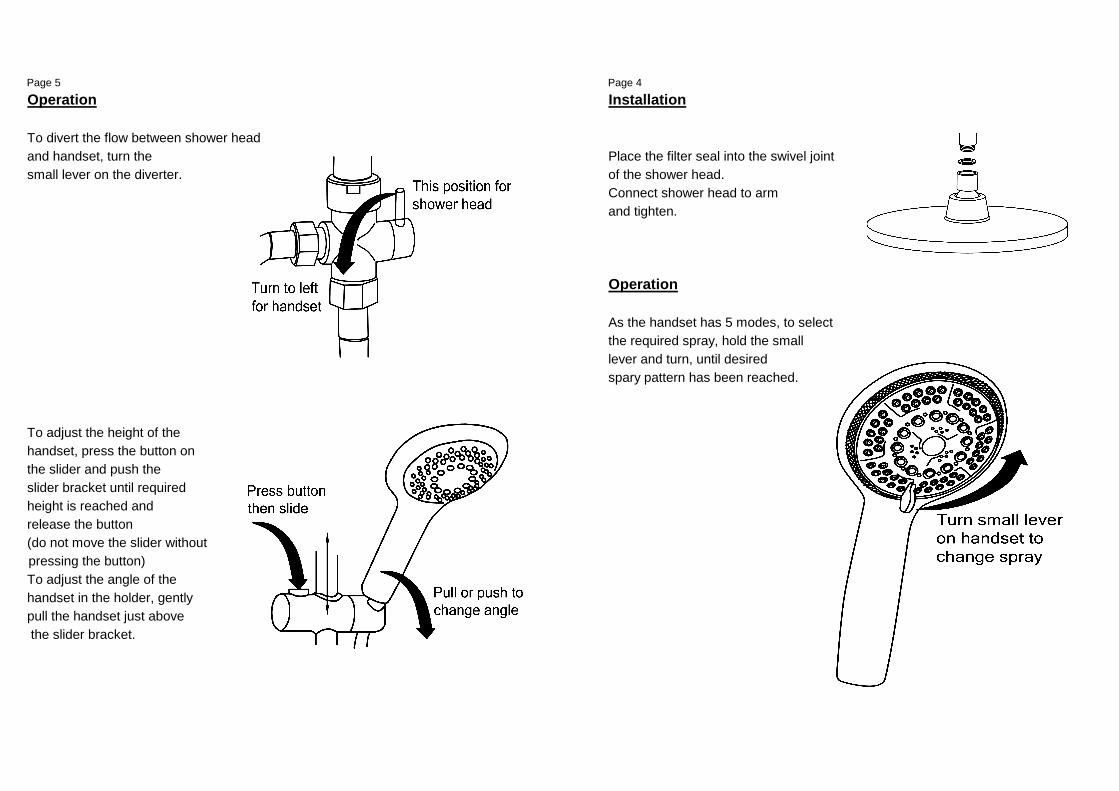
Operation Installation
To divert the flow between shower head
and handset, turn the Place the filter seal into the swivel joint
small lever on the diverter. of the shower head.
Connect shower head to arm
and tighten.
Operation
As the handset has 5 modes, to select
the required spray, hold the small
lever and turn, until desired
spary pattern has been reached.
To adjust the height of the
handset, press the button on
the slider and push the
slider bracket until required
height is reached and
release the button
(do not move the slider without
pressing the button)
To adjust the angle of the
handset in the holder, gently
pull the handset just above
the slider bracket.
Guarantee
Not covered by the guarantee is: Not covered by the guarantee is:
• Breakdown due to - • The cost of repair or replacement of pressure relief devices,
a) Use other than domestic spray heads, hoses, riser rails and/or wall bracket
b) Wilful act of neglect or any other accessories installed at the same time.
c) Any malfunction resulting from incorrect use
d) Incorrect setting of controls
e) Any malfunction resulting from poor water quality
• Repair costs for damage caused by foreign objects or substances • The cost of routine maintenance, adjustments, overhaul,
modifications, loss or damage, arising therefrom,
• Total loss of the product due to non-availability of parts including the cost of repairing damage, breakdown, malfunction
caused by corrosion, furring, pipe scaling, lime scale,
• Compensation for loss of use of the product or consequential system debris or frost.
loss of any kind.
• Call out charges where no fault has been found with the product.