R 984 C Mining Excavator Operating Weight with Backhoe Attachment: 120,100 kg / 264,775 lb Operating Weight with Shovel Attachment: 125,100 kg / 275,798 lb Engine Output: 504 kW / 685 hp Bucket Capacity: 2.90 - 8.00 m³ / 3.7 - 10.4 yd³ Shovel Capacity: 5.70 - 9.00 m³ / 7.4 - 11.7 yd³
Transcript
NTB_R984C_BT_enGB.indd 1 01.04.10 07:44
R 984 CMining ExcavatorOperating Weight with Backhoe Attachment: 120,100 kg / 264,775 lbOperating Weight with Shovel Attachment: 125,100 kg / 275,798 lbEngine Output: 504 kW / 685 hpBucket Capacity: 2.90 - 8.00 m³ / 3.7 - 10.4 yd³Shovel Capacity: 5.70 - 9.00 m³ / 7.4 - 11.7 yd³
NTB_R984C_BT_enGB.indd 1 01.04.10 07:50
2
NTB_R984C_BT_enGB.indd 2 01.04.10 07:44
R 984 C
R 984 COperating Weight with Backhoe Attachment: 120,100 kg / 264,775 lb
Operating Weight with Shovel Attachment: 125,100 kg / 275,798 lb
Engine Output: 504 kW / 685 hp
Bucket Capacity: 2.90 - 8.00 m³ / 3.7 - 10.4 yd³
Shovel Capacity: 5.70 - 9.00 m³ / 7.4 - 11.7 yd³
NTB_R984C_BT_enGB.indd 2 01.04.10 07:50
3
NTB_R984C_BT_enGB.indd 3 01.04.10 07:44
R 984 C
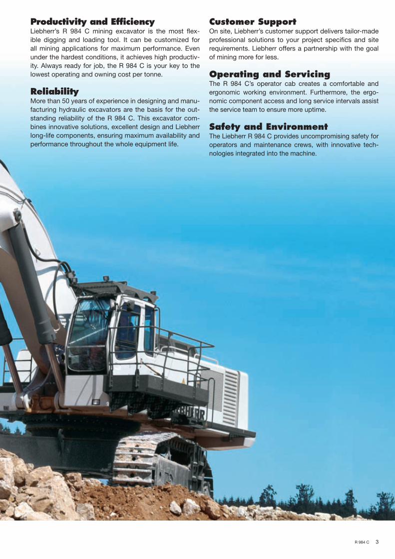
Productivity and EfficiencyLiebherr’s R 984 C mining excavator is the most fl ex-
ible digging and loading tool. It can be customized for
all mining applications for maximum performance. Even
under the hardest conditions, it achieves high productiv-
ity. Always ready for job, the R 984 C is your key to the
lowest operating and owning cost per tonne.
Reliability More than 50 years of experience in designing and manu-
facturing hydraulic excavators are the basis for the out-
standing reliability of the R 984 C. This excavator com-
bines innovative solutions, excellent design and Liebherr
long-life components, ensuring maximum availability and
performance throughout the whole equipment life.
Customer SupportOn site, Liebherr’s customer support delivers tailor-made
professional solutions to your project specifi cs and site
requirements. Liebherr offers a partnership with the goal
of mining more for less.
Operating and ServicingThe R 984 C’s operator cab creates a comfortable and
ergonomic working environment. Furthermore, the ergo-
nomic component access and long service intervals assist
the service team to ensure more uptime.
Safety and EnvironmentThe Liebherr R 984 C provides uncompromising safety for
operators and maintenance crews, with innovative tech-
nologies integrated into the machine.
NTB_R984C_BT_enGB.indd 3 01.04.10 07:50
4
NTB_R984C_BT_enGB.indd 4 01.04.10 07:45
R 984 C
Quick Change Adapter
The optional Liebherr quick change
adapter assists in changing tools like
bucket or ripper without getting out
of the cab. This considerably saves
time compared to changing hydrau-
lic flexible devices:
• No nuts or pins needed
• No assembly and disassembly
of the axis
• Remote control from inside cab
• No manual intervention needed
NTB_R984C_BT_enGB.indd 4 01.04.10 07:50
5
NTB_R984C_BT_enGB.indd 5 01.04.10 07:45
R 984 C
Productivity and Efficiency
Regeneration System
Retraction of attachment cylinders
without pump energy:
• Pump flow can be used for other
cylinder motions during retraction
of boom cylinders
• Reduced fuel consumption
• Saving of time
Highest Digging and Breakout Forces
• Advanced attachment technology
and design for optimized digging
and breakout force distribution
• Strong structure design
• Liebherr heavy duty bucket solution
Liebherr’s R 984 C mining excavator is the most fl exible digging and loading tool.
It can be customized for all mining applications for maximum performance. Even
under the hardest conditions, it achieves high productivity. Always ready for job,
the R 984 C is your key to the lowest operating and owning cost per tonne.
Reach a New Level of ProductivityHigh Digging Forces With a multitude of possible backhoe attachments
confi gurations and a wide range of buckets the R 984 C provides the highest crowd and breakout forces in every application. Even under tough conditions Lieb-herr’s R 984 C high digging force allows easy bucket penetration and favorable bucket fi ll factors to achieve high productivity.
Closed Loop SwingCircuit
With an independent swing circuit the machine al-lows the maximum swing torque whilst retaining the full oil fl ow for the working circuit.
Compact MachineDesign
Liebherr’s excavator design is well-balanced and provides best machine stability. The high weight dis-tribution towards the undercarriage contributes to an effi cient utilization of the strong digging forces and a favorable power to weight ratio of the uppercarriage and attachment.
Efficiency for Less CostEffi cient CoolingSystem
Liebherr’s large dimensioned cooling system reducesfan power consumption and ensures an ideal machine temperature. The hydrostatic fans operate always onthe required level.
High HydraulicEffi ciency
The high pressure level of Liebherr hydraulic system together with the optimized pipe and hose layout maximize the usable power transmission. The Pres-sure Less Boom Down function combined with the oil regeneration on the attachment saves energy and reduces swing back time.
Automatic IdleControl
The electronic control of the hydraulic system and engine allows automatic idle mode contributing to less fuel consumption and load on the engine.
NTB_R984C_BT_enGB.indd 5 01.04.10 07:50
6
NTB_R984C_BT_enGB.indd 6 01.04.10 07:45
R 984 C
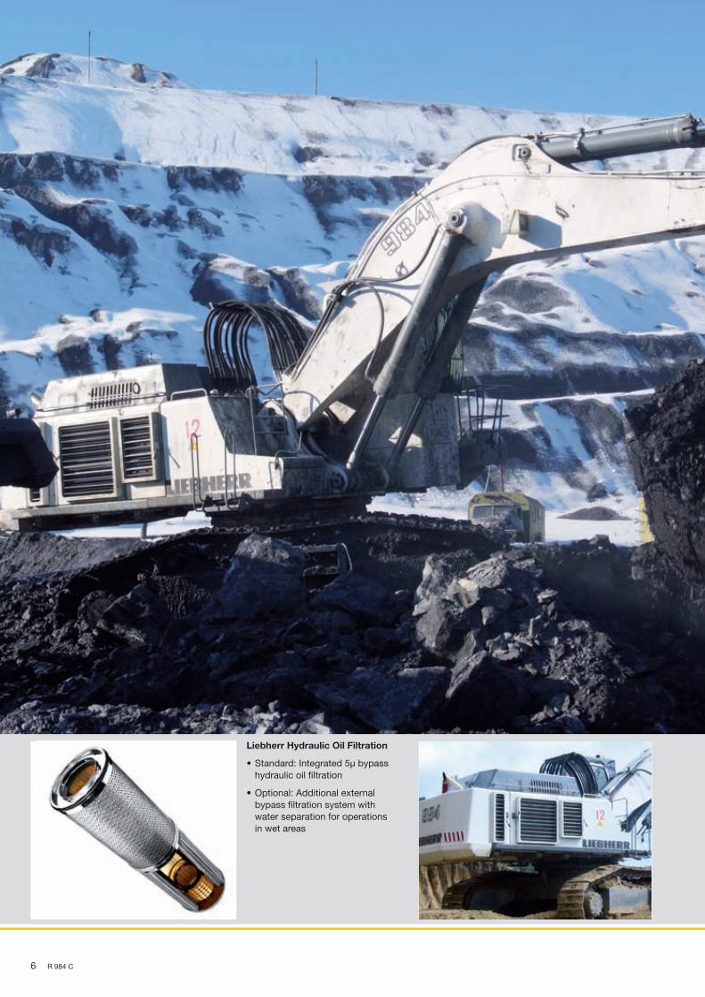
Liebherr Hydraulic Oil Filtration
• Standard: Integrated 5μ bypass
hydraulic oil filtration
• Optional: Additional external
bypass filtration system with
water separation for operations
in wet areas
NTB_R984C_BT_enGB.indd 6 01.04.10 07:50
7
NTB_R984C_BT_enGB.indd 7 01.04.10 07:45
R 984 C
Reliability
Liebherr Components
• Major components developed
and manufactured in-house
• Designed specifically for mining operations
• Liebherr Service Exchange Program
Cold / Hot Temperature Kit
Designed for maximum reliability in
regions with temperatures of down to
-40°C / -40°F or up to 55°C / 131°F.
• Integrated into machine structure
• Maximum efficiency
• Increases machine and component
lifetime
• Optimum operator comfort even in
hard temperature conditions
More than 50 years of experience in designing and manufacturing hydraulic ex-
cavators are the basis for the outstanding reliability of the R 984 C. This ex-
cavator combines innovative solutions, excellent design and Liebherr long-life
components, ensuring maximum availability and performance throughout the
whole equipment life.
Experience Liebherr QualityOver 50 Years ofExperience
Since 1954, Liebherr has been designing, manufac-turing and servicing crawler mounted excavators used in toughest applications. Like its predeces-sors, Liebherr’s R 984 C benefi ts from this long-time experience in the customer-focused design with modern engineering solutions and extensive mining knowledge.
Quality Management Liebherr’s quality processes commence with the machine design and simulations. Liebherr meets the highest industry standards for special selections of steels and selection of special casting materials. During manufacturing and assembly, Liebherr qual-ity management follows all manufacturing steps, ensuring highest quality of each machine delivered. Liebherr hydraulic excavator plants are ISO 9001 certifi ed.
Heavy DutyExcavator
First-class components and machine steel struc-tures ensure a high machine reliability, even in hard mining conditions.
Advanced Design of All Mining ApplicationsMachine Design Liebherr’s design processes include the latest and
product specifi c numerical engineering tools, such as Finite Element Analyses, Fatigue Calculations, Torque and Displacement Analysis and Multibody Simulations. These modern techniques allow reli-able engineering solutions for series and special ap-plications.
Specifi c Solutions As each project is unique, Liebherr is developing and supplying solutions to ensure performance and reliability in specifi c mining environments. Liebherr’s R 984 C can be customized to operate in regions with temperatures of down to -40°C / -40°F or up to 55°C / 131°F, as well as in high-altitude regions of up to 4,000 m above sea level. Liebherr also offers specifi c bucket-tailored solutions for each type of application.
NTB_R984C_BT_enGB.indd 7 01.04.10 07:50
8
NTB_R984C_BT_enGB.indd 8 01.04.10 07:45
R 984 C
Service Exchange Units (SEU)
Rebuild programs for compo-
nents are conducted by Liebherr-
certifi ed repair shops, using best
practice guidance to ensure:
• Maximum component life
• Long-term reliability
• High performance
• Cost-effi ciency
• High quality
NTB_R984C_BT_enGB.indd 8 01.04.10 07:50
9
NTB_R984C_BT_enGB.indd 9 01.04.10 07:45
R 984 C
Customer Support
Liebherr Service Tools
• Fast component replacement
• Designed specifi cally for require-
ments on Liebherr machines
• High operational safety
• Cost-effi ciency for service
operations
• Usable on different excavator sizes
Liebherr Training Programs
Competence-based training,
employing an interdisciplinary
learning strategy:
• Liebherr Mining Training Centers
• Available in different languages
• Customized training courses on site
On site, Liebherr’s customer support delivers tailor-made professional solutions
to your project specifi cs and site requirements. Liebherr offers a partnership with
the goal of mining more for less.
Your Mining PartnerParts Logistics andServices
Liebherr parts and service follow the machine into the fi eld with international logistics platforms ensuring parts supply and maintenance services worldwide.
Customized Serviceand Product Support
Depending on specifi c requirements, Liebherr offers tailored support solutions integrating parts exchange and management agreements, service and mainte-nance on site or maintenance management agree-ments.
Service ExchangeUnits
Rebuild programs for components are conducted by Liebherr-certifi ed repair shops, ensuring rebuilt component life and reliability match new component performance expectations.
Complete TrainingSolutions
Dedicated to mining the Liebherr training team pro-vides operator and maintenance staff training pro-grams to allow cost-effi cient and safe operations. Liebherr offers customized on-site training courses according to your needs.
Factory SupportService Engineering Liebherr design and fi eld service engineers accom-
pany the excavators throughout the whole machine life. Liebherr’s sales and service organizations and the Liebherr factories’ product engineering groups provides fast and proactive support to the mining in-dustry.
Service Tools Liebherr affords service tools for excavator-specifi c maintenance which ensure safe working even when hand-ling large excavator components.
NTB_R984C_BT_enGB.indd 9 01.04.10 07:50
10
NTB_R984C_BT_enGB.indd 10 01.04.10 07:45
R 984 C
Comfort in Cab
• Outstanding visibility over the
whole working environment
• Automatic air condition
• Tinted laminated safety glass
• Pressurized to prevent dust penetration
• Low vibration and super silent
• Adjustable seat
NTB_R984C_BT_enGB.indd 10 01.04.10 07:50
11
NTB_R984C_BT_enGB.indd 11 01.04.10 07:45
R 984 C
Operating and ServicingThe R 984 C’s operator cab creates a comfortable and ergonomic working envi-
ronment. The ergonomically optimized machine controls assure the best operator
performance throughout each shift. Furthermore, the ergonomic component access
and long service intervals assist the service team to ensure more uptime.
Operator WorkplaceComfortableWorkingEnvironment
The large R 984 C’s spacious cab offers ideal work-ing conditions and fi rst-class comfort. The fully ad-justable seat and control fi ts to individual needs. The position of the operator station together with the large windows allow an outstanding visibility over the whole working environment. The cab’s effective insu-lation creates a quiet working environment for maxi-mum productivity.
Ergonomic ControlElements
The confi guration and placement of operator con-trol elements and monitoring displays are perfectly coordinated to support the productive performance. The electronic control is easy and intuitive to use. The dashboard and machine control panel are easy to access and arranged for fast overview on major machine functions.
Easy ServiceabilityErgonomic ServiceAccess
The R 984 C provides ergonomic component access for fast and effi cient service. All service points are within reach through large catwalks and walkways. The optional ground fast fi lling connections gives easy and safe refi lling of service fl uids, saving time, preventing spillage and reducing contamination by dust. The electronic health monitoring system as-sists in trouble-shooting and maintenance tasks. Liebherr excavators are equipped with louvers for easy access of ground based support tools.
Extended ServiceIntervals
The R 984 C offers all features for extended machine services intervals. The technical layout of fi ltration systems with integrated bypass hydraulic oil fi lters and the large dimensioned grease systems are only some examples.
Ergonomic Service Access
Safe and effi cient service through:
• Large catwalk and platform
• All service points on engine, fan drive
and hydraulic valve blocks are ac-
cessed from one large central platform
• Hinged louvers for easy cleaning and
maintenance tasks
• Optional fast fi lling connections
Automatic Greasing System
All attachment and swing ring lubrica-
tion points are connected to the auto-
matic lubrication system
• Robust single line central lubrication
system
• Adjustable injectors
• Greasing points are protected
against external damages
• Grease control in operator’s reach
in the cab
NTB_R984C_BT_enGB.indd 11 01.04.10 07:50
12
NTB_R984C_BT_enGB.indd 12 01.04.10 07:45
R 984 C
Safe machine access
• Optional uppercarriage mounted
re-tractable access ladder
• Access ladders and catwalks feature
handrails and slip-resistant surfaces
• Emergency egress with handrail
at the front of the excavator
• Optional wide catwalk with railings
NTB_R984C_BT_enGB.indd 12 01.04.10 07:50
13
NTB_R984C_BT_enGB.indd 13 01.04.10 07:46
R 984 C
Safety and EnvironmentThe Liebherr R 984 C provides uncompromising safety for operators and mainte-
nance crews, with innovative technologies integrated into the machine.
Safety Integrated DesignEasy and SafeMachine Access
All railings and catwalks are laid out to easily access all relevant machine areas. An optional wide catwalk is available.
Protected Operatorand Service Crew
The laminated windows create a safe working en-vironment for operators. Emergency stop arrange-ments in the cab and optionally in the engine com-partment ensure safe maintenance tasks. Safety standards are achieved by a separated engine and pump compartment, heat insulation on turbocharg-ers and on the exhaust system as well as by the use of heavy duty high resistant hydraulic hoses.
Environmental CareEco Features Throughout the whole design and manufacturing
process of Liebherr machines, environmental pro-tection is given high priority. Material used for ma-chine assembly is recyclable at 95 %. The hydraulic system allows the use of biodegradable hydraulic oils. The automatic idle mode contributes to less fuel consumption and less load on the engine resulting in reduced CO2 emissions.
Effi ciency andEnvironmentalStandards
Powered with the Cummins QSK 19 diesel engine EPA Tier 2 or 3, the R 984 C offers fuel-effi cient op-erations meeting the latest emission standards.
Fire Suppression System (optional)
• Dry chemical system
• Checkfi re control module including
automatic detection / actuation
• Anti-restart relay (1 hour) after operatingn
of the fi re suppression system
Optional Safety Features
• Kit for Mining and Quarry Application
including : emergency stop button,
fi re extinguisher and protective grid
on the top of the cab
• Cab protection FOPS
• Protective grid for front cab window
• Travel alarm
NTB_R984C_BT_enGB.indd 13 01.04.10 07:50
14 R 984 C
Technical Data
Engine1 Cummins diesel engineRating per ISO 9249 ��������� 523 kW/710 hp at 2,100 rpm
reduced to 504 kW/675 hp at 1,800 rpmModel ����������������������������� QSK-19 C 750Type �������������������������������� 6 cylinder in-line engine Bore/Stroke ���������������� 159/159 mm / 6.26/6.26 in Displacement ������������� 18.9 l/1,153 in3
Cooling ��������������������������� water-cooledAir cleaner ����������������������� dry-type air cleaner with pre-cleaner,
primary and safety elements, automatic dust discharge
Fuel tank ������������������������� 1,585 l/419 galStandard ������������������������� sensor controlled engine idlingElectrical system Voltage ���������������������� 24 V Batteries �������������������� 2 x 144 Ah/12 V Starter ����������������������� 24 V/9.0 kW Alternator ������������������� three phase current 24 V/100 A
Hydraulic SystemHydraulic pump for attachment and travel drive ����������������� 3 Liebherr variable flow, swash plate
pumps Max. flow ������������������� 3 x 472 l/min. / 3 x 125 gpm Max. pressure ������������� 320 bar/4,640 psiPump regulation ��������������� electro-hydraulic with electronic engine
closed-loop circuit Max. flow ������������������� 403 l/min. / 106 gpm Max. pressure ������������� 340 bar/4,931 psiHydraulic tank ������������������ 880 l/232 galHydraulic system �������������� 1,660 l/438 galHydraulic oil filter �������������� 2 full flow filters in return line with inte-
grated fine filter area (5 µm), 1 high pres-sure filter for each main pump
Cooler ����������������������������� compact cooler, consisting of a water cooler, sandwiched with hydraulic oil cooler, aftercooler cores and air condi-tioning, hydrostatically driven fan
MODE selection ��������������� adjustment of machine performance and the hydraulics via a mode selector to match application
LIFT ��������������������������� for lifting FINE �������������������������� for precision work and lifting with sensitive
movements ECO �������������������������� for economical operation POWER ��������������������� for maximum digging power and heavy
duty jobsRPM adjustment ��������������� stepless adjustment of engine output via
rpm at each selected mode
Hydraulic ControlsPower distribution ������������ via monoblock control valves with inte-
grated safety valves Flow summation ��������� to boom stick and bucket cylinders Closed-loop circuit ����� for uppercarriage swing driveServo circuit Attachment and swing ������������������������ proportional via joystick levers Travel ������������������������ proportional via foot pedals or removable
hand leversAdditional functions ���������� via foot pedals or joystick toggle switch
Electric SystemElectric isolation ��������������� easy accessible battery isolationsWorking lights ������������������ high brightness halogen lights:
– 2 on working attachment – 2 on RHS of uppercarriage – 1 on LHS of uppercarriage Xenon lights in option
Emergency stop switches �� in the cab/in option in engine compartmentElectrical wiring ���������������� heavy duty execution in IP 65 standard for
operating conditions of – 50 °C to 100 °C/ – 58 °F to 212 °F
Swing DriveDrive by ��������������������������� Liebherr swash plate motorTransmission �������������������� Liebherr compact planetary reduction gearSwing ring ����������������������� Liebherr, sealed single race ball bearing
released)Brake valves �������������������� integrated in main valve block
AttachmentType �������������������������������� box-type, combination of resistant steel
plates and cast steel componentsHydraulic cylinders ����������� Liebherr designPivots ������������������������������ sealed, low maintenancePivots bucket-to-stickbucket-to-link ������������������ O-ring sealed and completely enclosedHydraulic connections ������ pipes and hoses equipped with SAE split-
flange connections
Central Lubrication SystemType �������������������������������� Lincoln Centromatic lubrication system, for
the entire attachment/swing ring bearing and teeth
Grease pumps ������������������ 1 Lincoln lubrigun (pneumatic) pump for attachment/swing ring bearing lubrication (Lincoln Flowmaster hydraulic pump in option) 1 Lincoln P203 (electric) pump for swing teeth lubrication
Capacity �������������������������� 30 l/7.9 gal bulk container for attachment/swing ring bearing, separated 8 l/2.1 gal container for swing ring teeth
Refill ������������������������������� via quick connection and grease filter for the attachment/swing ring bearing circuit via filling point located direclty on the pump for the swing ring teeth circuit
Stick lengths m 3.40 4.50 ft in 11’ 1” 14’9”Max. digging depth m 7.95 9.05 ft in 26’ 29’8”Max. reach at ground level m 13.70 14.75 ft in 44’11” 48’4”Max. dump height m 9.20 9.80 ft in 30’2” 32’1”Max. teeth height m 14.00 14.65 ft in 45’11” 48’
Max. digging force (SAE) kN 416 346 lbf 93,521 77,784Max. breakout force (SAE) kN 550 550 lbf 123,645 123,645
Operating Weight and Ground PressureThe operating weight includes the basic machine with gooseneck boom 7.80 m/25’7”, stick 3.40 m/11’1” and bucket 7.00 m3/9.16 yd3.
Undercarriage HD
Pad width mm/ft in 600/1’11” 750/2’5”Weight kg/lb 120,100/264,775 121,300/267,420Ground pressure kg/cm2 / psi 1.80/25.60 1.46/20.77
BucketsFor materials classe according to VOB, Section C, DIN 18300 < 5 < 5 < 5 5 – 6 5 – 6 5 – 6 7 – 8 7 – 8 7 – 8Typical operation according to VOB, Section C, DIN 18300 GP GP GP HD HD HD XHD XHD XHDCapacity ISO 7451 m3 8.00 7.30 6.70 7.70 7.00 6.40 6.70 6.20 5.80 yd3 10.46 9.55 8.76 10.07 9.16 8.37 8.76 8.11 7.59Suitable for material up to a specific weight ofwith stick 3.40 m t/m3 1.6 1.8 2.0 1.6 1.8 2.0 1.6 1.8 2.0with stick 11’1” lb/yd3 2,698 3,035 3,373 2,698 3,035 3,373 2,698 3,035 3,373with stick 4.50 m t/m3 – 1.5 1.65 – 1.5 1.65 – – 1.65with stick 14’9” lb/yd3 – 2,530 2,782 – 2,530 2,782 – – 2,782Cutting width mm 2,600 2,400 2,250 2,550 2,400 2,250 2,600 2,500 2,500 ft in 8’6” 7’10” 7’4” 8’4” 7’10” 7’4” 8’6” 8’2” 8’2”Weight kg 7,200 6,800 6,600 7,700 7,500 7,200 9,300 9,000 8,200 lb 15,873 14,991 14,550 16,976 16,535 15,873 20,503 19,842 18,078
GP: General purpose bucket with Esco V 69 SD teethHD: Heavy-duty bucket with Esco V 71 SD teethXHD: Heavy-duty rock bucket with Esco V 71 SD teeth
NTB_R984C_T_enGB-US_10-03.indd 17 26.03.10 10:57
18 R 984 C
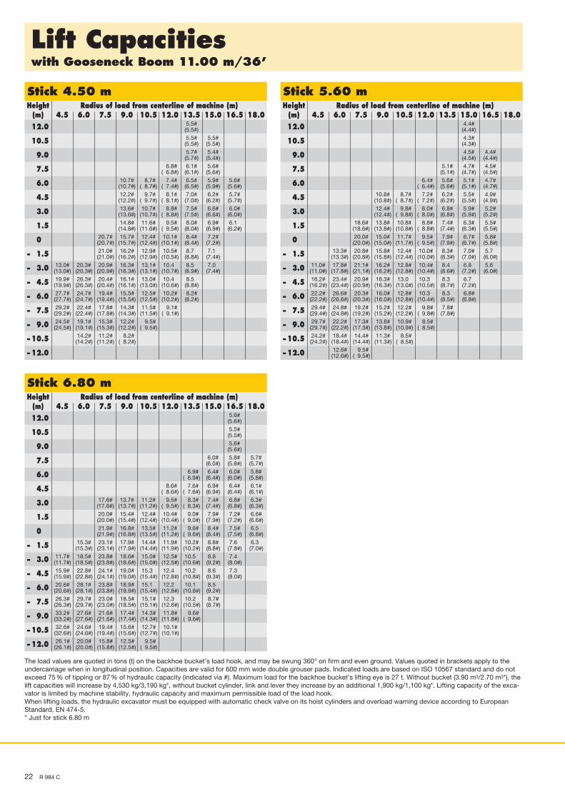
Lift Capacitieswith Gooseneck Boom 7.80 m/25’7”
Stick 3.40 m Height Radius of load from centerline of machine (m) (m) 3.0 4.5 6.0 7.5 9.0 10.5 12.0 13.5 15.0 16.5 12.0
The load values are quoted in tons (t) on the backhoe bucket’s load hook, and may be swung 360° on firm and even ground. Values quoted in brackets apply to the undercarriage when in longitudinal position. Capacities are valid for 600 mm wide double grouser pads. Indicated loads are based on ISO 10567 standard and do not exceed 75 % of tipping or 87 % of hydraulic capacity (indicated via #). Maximum load for the backhoe bucket’s lifting eye is 27 t. Without bucket (6.40 m3), the lift capacities will increase by 7,200 kg, without bucket cylinder, link and lever they increase by an additional 1,900 kg. Lifting capacity of the excavator is limited by machine stability, hydraulic capacity and maximum permissible load of the load hook.When lifting loads, the hydraulic excavator must be equipped with automatic check valve on its hoist cylinders and overload warning device according to European Standard, EN 474-5.
Stick lengths m 3.40 4.50 5.60 6.80 ft in 11’1” 14’9” 18’4” 22’3”Max. digging depth m 9.25 10.35 11.45 12.30 ft in 30’4” 33’11” 37’6” 40’4”Max. reach at ground level m 15.20 16.25 17.35 18.10 ft in 49’10” 53’3” 56’10” 59’4”Max. dump height m 10.20 10.85 11.45 12.20 ft in 33’5” 35’7” 37’6” 40’Max. teeth height m 15.00 15.70 16.35 16.40 ft in 49’2” 51’5” 53’7” 53’9”
* with stick 6.80 m with R 974 B litronic̀ buckets
Operating Weight and Ground PressureThe operating weight includes the basic machine with gooseneck boom 7.80 m/25’7”, stick 3.40 m/11’1” and bucket 7.00 m3/9.16 yd3.
Undercarriage HD
Pad width mm/ft in 600/1’11” 750/2’5”Weight kg/lb 118,800/261,909 120.000/264,554Ground pressure kg/cm2 / psi 1.78/25.32 1.44/20.48
1) Medium-duty bucket with teeth size V 69 SD (appropriate for materials up to classification 5, according to VOB, Section C, DIN 18300)2) Bucket R 974 B litronic̀
NTB_R984C_T_enGB-US_10-03.indd 19 26.03.10 10:57
20 R 984 C
Lift Capacitieswith Gooseneck Boom 9.20 m/30’2”
Stick 3.40 m Height Radius of load from centerline of machine (m) (m) 4.5 6.0 7.5 9.0 10.5 12.0 13.5 15.0 16.5 18.0 12.0
The load values are quoted in tons (t) on the backhoe bucket’s load hook, and may be swung 360° on firm and even ground. Values quoted in brackets apply to the undercarriage when in longitudinal position. Capacities are valid for 600 mm wide double grouser pads. Indicated loads are based on ISO 10567 standard and do not exceed 75 % of tipping or 87 % of hydraulic capacity (indicated via #). Maximum load for the backhoe bucket’s lifting eye is 27 t. Without bucket (3.90 m3/2.70 m3*), the lift capacities will increase by 4,530 kg/3,190 kg*, without bucket cylinder, link and lever they increase by an additional 1,900 kg/1,100 kg*. Lifting capacity of the exca-vator is limited by machine stability, hydraulic capacity and maximum permissible load of the load hook.When lifting loads, the hydraulic excavator must be equipped with automatic check valve on its hoist cylinders and overload warning device according to European Standard, EN 474-5.* Just for stick 6.80 m
NTB_R984C_T_enGB-US_10-03.indd 20 26.03.10 10:57
R 984 C 21
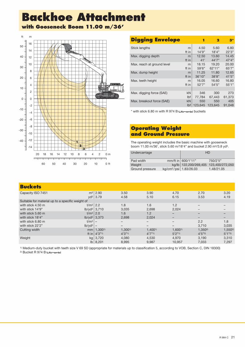
Backhoe Attachmentwith Gooseneck Boom 11.00 m/36’
0 m2468101214161820
0 ft102030405060
0
-2
-4
-6
-8
-10
-12
-14
0
-10
-20
-30
-40
2
4
6
8
10
12
14
16
m
10
20
30
40
50
ft
32
1
BucketsCapacity ISO 7451 m3 2.90 3.50 3.90 4.70 2.70 3.20 yd3 3.79 4.58 5.10 6.15 3.53 4.19Suitable for material up to a specific weight ofwith stick 4.50 m t/m3 2.2 1.8 1.6 1.2 – –with stick 14’9” lb/yd3 3,710 3,035 2,698 2,024 – –with stick 5.60 m t/m3 2.0 1.6 1.2 – – –with stick 18’4” lb/yd3 3,373 2,698 2,024 – – –with stick 6.80 m t/m3 – – – – 2.2 1.8with stick 22’2” lb/yd3 – – – – 3,710 3,035Cutting width mm 1,3001) 1,3001) 1,4001) 1,6001) 1,3502) 1,5502)
1) Medium-duty bucket with teeth size V 69 SD (appropriate for materials up to classification 5, according to VOB, Section C, DIN 18300)2) Bucket R 974 B litronic̀
Digging Envelope 1 2 3*
Stick lengths m 4.50 5.60 6.80 ft in 14’9” 18’4” 22’3”Max. digging depth m 12.50 13.60 14.45 ft in 41’ 44’7” 47’4”Max. reach at ground level m 18.15 19.20 20.00 ft in 59’6” 62’11” 65’7”Max. dump height m 11.25 11.80 12.65 ft in 36’10” 38’8” 41’5”Max. teeth height m 16.05 16.60 16.80 ft in 52’7” 54’5” 55’1”
* with stick 6.80 m with R 974 B litronic̀ buckets
Operating Weight and Ground PressureThe operating weight includes the basic machine with gooseneck boom 11.00 m/36’, stick 5.60 m/18’4” and bucket 2.90 m3/3.8 yd3.
Undercarriage HD
Pad width mm/ft in 600/1’11” 750/2’5”Weight kg/lb 122,200/269,405 123,400/272,050Ground pressure kg/cm2 / psi 1.83/26.03 1.48/21.05
NTB_R984C_T_enGB-US_10-03.indd 21 26.03.10 10:57
22 R 984 C
Lift Capacitieswith Gooseneck Boom 11.00 m/36’
Stick 4.50 m Height Radius of load from centerline of machine (m) (m) 4.5 6.0 7.5 9.0 10.5 12.0 13.5 15.0 16.5 18.0 12.0
The load values are quoted in tons (t) on the backhoe bucket’s load hook, and may be swung 360° on firm and even ground. Values quoted in brackets apply to the undercarriage when in longitudinal position. Capacities are valid for 600 mm wide double grouser pads. Indicated loads are based on ISO 10567 standard and do not exceed 75 % of tipping or 87 % of hydraulic capacity (indicated via #). Maximum load for the backhoe bucket’s lifting eye is 27 t. Without bucket (3.90 m3/2.70 m3*), the lift capacities will increase by 4,530 kg/3,190 kg*, without bucket cylinder, link and lever they increase by an additional 1,900 kg/1,100 kg*. Lifting capacity of the exca-vator is limited by machine stability, hydraulic capacity and maximum permissible load of the load hook.When lifting loads, the hydraulic excavator must be equipped with automatic check valve on its hoist cylinders and overload warning device according to European Standard, EN 474-5.* Just for stick 6.80 m
Max. crowd force at ground level (SAE) 550 kN/123,645 lbfMax. crowd force (SAE) 750 kN/168,607 lbfMax. breakout force (SAE) 550 kN/123,645 lbf
Operating Weight and Ground PressureThe operating weight includes the basic machine with shovel attach-ment and a 7.00 m3/9.16 yd3 bucket.
Undercarriage HD
Pad width mm/ft in 600/1’11” 750/2’5”Weight kg/lb 125,100/275,798 126,300/278,444Ground pressure kg/cm2 / psi 1.88/26.74 1.48/21.05
Bottom Dump BucketsFor materials classe according to VOB, Section C, DIN 18300 < 5 < 5 5 – 6 5 – 6 5 – 6 7 – 8 7 – 8 7 – 8Typical operation according to VOB, Section C, DIN 18300 GP GP HD HD HD XHD XHD XHDCapacity ISO 7546 m3 9.00 7.70 7.70 7.00 5.70 7.00 7.00 5.70 yd3 11.77 10.07 10.07 9.16 7.46 9.16 9.16 7.46Suitable for material up to a specific weight of t/m3 1.3 1.7 1.5 1.8 2.3 1.5 1.8 2.2 lb/yd3 2,192 2,867 2,530 3,035 3,879 2,530 3,035 3,710Cutting width mm 2,900 2,900 2,900 2,900 2,500 2,900 2,900 2,500 ft in 9’6” 9’6” 9’6” 9’6” 8’2” 9’6” 9’6” 8’2”Weight kg 13,300 11,000 13,300 12,900 11,400 14,400 12,600 12,400 lb 29,321 24,251 29,321 28,440 25,133 31,747 27,778 27,337Wear kit level I I II II II III III III
GP: General purpose bucket with Esco V 69 RYL teethHD: Heavy-duty bucket with Esco V 69 RYL teethXHD: Heavy-duty rock bucket with Esco V 69 RYL teeth
Level I: For non-abrasive materials, such as limestone, without flint inclusion, shot material or easily breakable rock, i.e., deteriorated rock, soft limestone, shale, etc.
Level II: For preblasted heavy rock, or deteriorated, cracked material (classification 5 to 6, according to DIN 18300)Level III: For highly-abrasive materials such as rock with a high silica content, sandstone etc.
NTB_R984C_T_enGB-US_10-03.indd 23 26.03.10 10:57
24 R 984 C
Component Dimensions and Weights
Basic Machine (with Catwalks)Track pads mm/ft in 600/1’11” 750/2’5”Weight with counterweight 19,000 kg/41,888 lb kg/lb 89,140/196,520 90,330/199,143
Catwalks and Railings (Wooden Crate)L Length mm/ft in 3,500/11’ 5”H Height mm/ft in 2,400/ 7’10” Width mm/ft in 1,900/ 6’ 2” Weight kg/lb 1,800/3,968
CounterweightL Length mm/ft in 900/ 2’11” 900/ 2’11”*H Height mm/ft in 1,800/ 5’10” 1,800/ 5’10”* Width mm/ft in 4,050/13’ 3” 4,050/13’ 3”* Weight kg/lb 19,020/ 41,932 22,000/ 48,502*
* only with 11.00 m/36’ gooseneck boom
Protective Grid UpL Length mm/ft in 1,730/5’8”H Height mm/ft in 185/ 7” Width mm/ft in 950/3’1” Weight kg/lb 30/66
Front Window ScreenL Length mm/ft in 1,970/6’5”H Height mm/ft in 500/1’7” Width mm/ft in 970/3’2” Weight kg/lb 45/99
Cab ElevationL Length mm/ft in 1,950/6’4”H Height mm/ft in 1,130/3’8” Width mm/ft in 1,250/4’1” Weight kg/lb 600/1,323
L
H
H
L
L
H
H
L
L
H
L
H
L
H
L
H
L
L
L
H
L
L
H
H
H
L
L
H
X
H
D
R 984 C AusrüstungsteileSAaktualisiert am 11.02.2010
L
H
H
L
L
H
H
L
L
H
L
H
L
H
L
H
L
L
L
H
L
L
H
H
H
L
L
H
X
H
D
R 984 C AusrüstungsteileSAaktualisiert am 11.02.2010
L
H
H
L
L
H
H
L
L
H
L
H
L
H
L
H
L
L
L
H
L
L
H
H
H
L
L
H
X
H
D
R 984 C AusrüstungsteileSAaktualisiert am 11.02.2010
L
H
H
L
L
H
H
L
L
H
L
H
L
H
L
H
L
L
L
H
L
L
H
H
H
L
L
H
X
H
D
R 984 C AusrüstungsteileSAaktualisiert am 11.02.2010
L
H
H
L
L
H
H
L
L
H
L
H
L
H
L
H
L
L
L
H
L
L
H
H
H
L
L
H
X
H
D
R 984 C AusrüstungsteileSAaktualisiert am 11.02.2010
NTB_R984C_T_enGB-US_10-03.indd 24 26.03.10 10:57
R 984 C 25
Component Dimensions and Weights
L
H
H
L
L
H
H
L
L
H
L
H
L
H
L
H
L
L
L
H
L
L
H
H
H
L
L
H
X
H
D
R 984 C AusrüstungsteileSAaktualisiert am 11.02.2010
L
H
H
L
L
H
H
L
L
H
L
H
L
H
L
H
L
L
L
H
L
L
H
H
H
L
L
H
X
H
D
R 984 C AusrüstungsteileSAaktualisiert am 11.02.2010
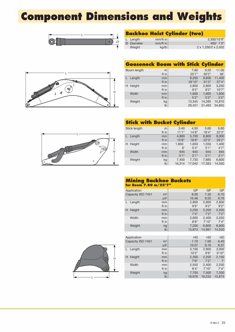
Backhoe Hoist Cylinder (two)L Length mm/ft in 3,300/10’9”Ø Diameter mm/ft in 400/ 1’3” Weight kg/lb 2 x 1,330/2 x 2,932
Gooseneck Boom with Stick CylinderBoom length m 7.80 9.20 11.00 ft in 25’7” 30’2” 36’L Length mm 8,200 9,600 11,400 ft in 26’10” 31’5” 37’4”H Height mm 2,800 2,800 3,250 ft in 9’2” 9’2” 10’7” Width mm 1,600 1,600 1,600 ft in 5’2” 5’2” 5’2” Weight kg 13,345 14,285 15,810 lb 29,421 31,493 34,855
L
H
H
L
L
H
H
L
L
H
L
H
L
H
L
H
L
L
L
H
L
L
H
H
H
L
L
H
X
H
D
R 984 C AusrüstungsteileSAaktualisiert am 11.02.2010
Stick with Bucket CylinderStick length m 3.40 4.50 5.60 6.80 ft in 11’1” 14’9” 18’4” 22’3”L Length mm 4,800 5,700 6,800 8,000 ft in 15’8” 18’8” 22’3” 26’2”H Height mm 1,850 1,650 1,550 1,400 ft in 6’ 5’4” 5’1” 4’7” Width mm 945 945 945 945 ft in 3’1” 3’1” 3’1” 3’1” Weight kg 7,400 7,730 7,885 6,600 lb 16,314 17,042 17,383 14,550
L
H
H
L
L
H
H
L
L
H
L
H
L
H
L
H
L
L
L
H
L
L
H
H
H
L
L
H
X
H
D
R 984 C AusrüstungsteileSAaktualisiert am 11.02.2010
Mining Backhoe Bucketsfor Boom 7.80 m/25’7”
Application GP GP GPCapacity ISO 7451 m3 8.00 7.30 6.70 yd3 10.46 9.55 8.76L Length mm 2,900 2,800 2,800 ft in 9’6” 9’2” 9’2”H Height mm 2,250 2,200 2,200 ft in 7’4” 7’2” 7’2” Width mm 2,600 2,400 2,250 ft in 8’6” 7’10” 7’4” Weight kg 7,200 6,800 6,600 lb 15,873 14,991 14,550
Application HD HD HDCapacity ISO 7451 m3 7.70 7.00 6.40 yd3 10.07 9.16 8.37L Length mm 3,100 2,900 3,000 ft in 10’2” 9’6” 9’10”H Height mm 2,300 2,200 2,150 ft in 7’6” 7’2” 7’ Width mm 2,550 2,400 2,250 ft in 8’4” 7’10” 7’4” Weight kg 7,700 7,500 7,200 lb 16,976 16,535 15,873
NTB_R984C_T_enGB-US_10-03.indd 25 26.03.10 10:57
26 R 984 C
Component Dimensions and Weights
Backhoe Bucketsfor Boom 9.20 m/30’2” and 11.00 m/36’
Capacity ISO 7451 m3 2.90 3.50 3.90 yd3 3.79 4.58 5.10L Length mm 2,700 2,900 2,900 ft in 8’10” 9’6” 9’6”H Height mm 2,100 2,250 2,250 ft in 6’10” 7’4” 7’4” Width mm 1,300 1,300 1,400 ft in 4’3” 4’3” 4’7” Weight kg 3,720 4,080 4,530 lb 8,201 8,995 9,987
Capacity ISO 7451 m3 4.70 5.50 6.20 yd3 6.15 7.19 8.11L Length mm 2,900 2,900 2,900 ft in 9’6” 9’6” 9’6”H Height mm 2,250 2,250 2,250 ft in 7’4” 7’4” 7’4” Width mm 1,600 1,800 2,000 ft in 5’2” 5’10” 6’6” Weight kg 4,970 5,280 5,700 lb 10,957 11,640 12,566
L
H
H
L
L
H
H
L
L
H
L
H
L
H
L
H
L
L
L
H
L
L
H
H
H
L
L
H
X
H
D
R 984 C AusrüstungsteileSAaktualisiert am 11.02.2010
Mining Backhoe Bucketsfor Boom 7.80 m/25’7”
Application XHD XHD XHDCapacity ISO 7451 m3 6.70 6.20 5.80 yd3 8.76 8.11 7.59L Length mm 3,100 3,150 2,950 ft in 10’2” 10’3” 9’8”H Height mm 2,200 2,200 2,200 ft in 7’2” 7’2” 7’2” Width mm 2,600 2,500 2,500 ft in 8’6” 8’2” 8’2” Weight kg 9,300 9,000 8,200 lb 20,503 19,842 18,078
L
H
H
L
L
H
H
L
L
H
L
H
L
H
L
H
L
L
L
H
L
L
H
H
H
L
L
H
X
H
D
R 984 C AusrüstungsteileSAaktualisiert am 11.02.2010
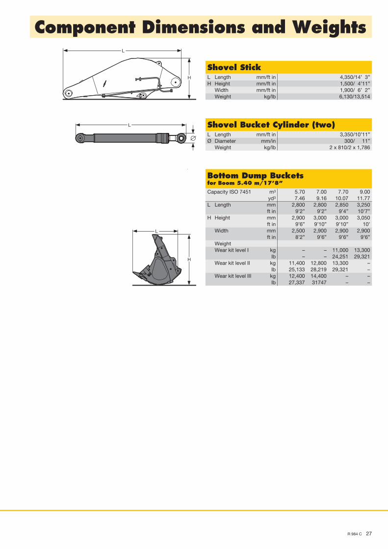
Shovel Hoist Cylinder (two)L Length mm/ft in 3,300/10’9”Ø Diameter mm/ft in 400/ 1’3” Weight kg/lb 2 x 1,330/2 x 2,932
L
H
H
L
L
H
H
L
L
H
L
H
L
H
L
H
L
L
L
H
L
L
H
H
H
L
L
H
X
H
D
R 984 C AusrüstungsteileSAaktualisiert am 11.02.2010
L
H
H
L
L
H
H
L
L
H
L
H
L
H
L
H
L
L
L
H
L
L
H
H
H
L
L
H
X
H
D
R 984 C AusrüstungsteileSAaktualisiert am 11.02.2010
Shovel BoomL Length mm/ft in 5,800/19’ H Height mm/ft in 2,400/ 7’10” Width mm/ft in 1,800/ 5’10” Weight without
crowd cylinder kg/lb 11,090/24,449 Weight
crowd cylinder kg/lb 563/1,241
NTB_R984C_T_enGB-US_10-03.indd 26 26.03.10 10:57
R 984 C 27
Component Dimensions and Weights
L
H
H
L
L
H
H
L
L
H
L
H
L
H
L
H
L
L
L
H
L
L
H
H
H
L
L
H
X
H
D
R 984 C AusrüstungsteileSAaktualisiert am 11.02.2010
L
H
H
L
L
H
H
L
L
H
L
H
L
H
L
H
L
L
L
H
L
L
H
H
H
L
L
H
X
H
D
R 984 C AusrüstungsteileSAaktualisiert am 11.02.2010
L
H
H
L
L
H
H
L
L
H
L
H
L
H
L
H
L
L
L
H
L
L
H
H
H
L
L
H
X
H
D
R 984 C AusrüstungsteileSAaktualisiert am 11.02.2010
Shovel StickL Length mm/ft in 4,350/14’ 3”H Height mm/ft in 1,500/ 4’11” Width mm/ft in 1,900/ 6’ 2” Weight kg/lb 6,130/13,514
Shovel Bucket Cylinder (two)L Length mm/ft in 3,350/10’11”Ø Diameter mm/in 300/ 11” Weight kg/lb 2 x 810/2 x 1,786
Bottom Dump Bucketsfor Boom 5.40 m/17’8”
Capacity ISO 7451 m3 5.70 7.00 7.70 9.00 yd3 7.46 9.16 10.07 11.77L Length mm 2,800 2,800 2,850 3,250 ft in 9’2” 9’2” 9’4” 10’7”H Height mm 2,900 3,000 3,000 3,050 ft in 9’6” 9’10” 9’10” 10’ Width mm 2,500 2,900 2,900 2,900 ft in 8’2” 9’6” 9’6” 9’6” Weight Wear kit level I kg – – 11,000 13,300 lb – – 24,251 29,321 Wear kit level II kg 11,400 12,800 13,300 – lb 25,133 28,219 29,321 – Wear kit level III kg 12,400 14,400 – – lb 27,337 31747 – –
NTB_R984C_T_enGB-US_10-03.indd 27 26.03.10 10:58
Equipment
• = Standard, + = Option
Options and/or special attachments, supplied by vendors other than Liebherr, are only to be installed with the knowledge and approval of Liebherr to retain warranty.
UndercarriageThree track guides per track •Integrated travel drive •Digging locks •Different undercarriage versions +Different track pad width +
Operator’s CabProfile and deep drawn component •Tinted side windows •Armored windshield •Door with sliding window •Washer and wiper •6-way adjustable cloth suspension seat •Seat and consoles independently adjustable •Coat hook •Dome light •Sun blinds •Radio installation prep-kit •Removable handle for travel pedals •Cigar lighter and ashtray •Removable custom floor mat •Storage and literature tray •Digital instrumentation •Digital instruments for oil temp. engine RPM and oil pressure •Digital hour meter visible from outside •Automatic air conditioning system •AM/FM stereo radio with USB connection +Air power seat adjustment with heating +Warning beacon +Additional flood lights +Bluetooth connection for mobile phone +
UppercarriageEngine hood with lift help •Lockable tool box •Handrails, non slip surfaces •Tool kit •Maintenance-free swing brake lock •Maintenance-free HD-batteries •Sound insulation •Electric fuel tank filler pump +Pedal controlled positioning swing brake +Customized paint – compl. machine +Protection for front working light +Heavy counterweight +
HydraulicsElectronic pump regulation •Stepless work mode selector •Pressure storage for controlled lowering of attachments with engine turned off •Hydraulic tank shut-off valve •Pressure compensation •Flow compensation •Filter with integrated fine filter area (5 µm) •Pressure test ports •Additional hydraulic circuits +Bio-degradable hydraulic oils +Filter for secondary circuit +
AttachmentCylinders with shock absorber •Sealed pivots •Two flood lights on the boom •Bucket mounted 27 t lifting eye •Automatic lubrication system Lincoln “Centromatic” for attachment and swing ring •Safety check valves on the hoist cylinders (only on 528 series) •Overload warning device +Hydraulic quick change tool adapter +Liebherr equipment program +Special buckets +Cylinder – rod protection +Additional piping for hydraulic tools +3,40 m/11’1” stick equipped for additional pipings +Engine
Direct injection •Turbo charger •Air filter with pre-cleaner, main and safety element •Air filter with automatic dust ejector •Automatic idling •Main switch for electric circuit •Cold start aid •Fuel pre-heater +