SANDIA REPORT SAND2004-6572 Unlimited Release Printed January 2005 MiniSAR Composite Gimbal Arm Development Mark Winscott and Paul R. Klarer Prepared by Sandia National Laboratories Albuquerque, New Mexico 87185 and Livermore, California 94550 Sandia is a multiprogram laboratory operated by Sandia Corporation, a Lockheed Martin Company, for the United States Department of Energy under Contract DE-AC04-94AL85000. Approved for public release; further dissemination unlimited.
Transcript
SANDIA REPORT SAND2004-6572 Unlimited Release Printed January 2005
MiniSAR Composite Gimbal Arm Development Mark Winscott and Paul R. Klarer
Prepared by Sandia National Laboratories Albuquerque, New Mexico 87185 and Livermore, California 94550 Sandia is a multiprogram laboratory operated by Sandia Corporation, a Lockheed Martin Company, for the United States Department of Energy under Contract DE-AC04-94AL85000. Approved for public release; further dissemination unlimited.
Issued by Sandia National Laboratories, operated for the United States Department of Energy by Sandia Corporation.
NOTICE: This report was prepared as an account of work sponsored by an agency of the United States Government. Neither the United States Government, nor any agency thereof, nor any of their employees, nor any of their contractors, subcontractors, or their employees, make any warranty, express or implied, or assume any legal liability or responsibility for the accuracy, completeness, or usefulness of any information, apparatus, product, or process disclosed, or represent that its use would not infringe privately owned rights. Reference herein to any specific commercial product, process, or service by trade name, trademark, manufacturer, or otherwise, does not necessarily constitute or imply its endorsement, recommendation, or favoring by the United States Government, any agency thereof, or any of their contractors or subcontractors. The views and opinions expressed herein do not necessarily state or reflect those of the United States Government, any agency thereof, or any of their contractors. Printed in the United States of America. This report has been reproduced directly from the best available copy. Available to DOE and DOE contractors from U.S. Department of Energy Office of Scientific and Technical Information P.O. Box 62 Oak Ridge, TN 37831 Telephone: (865)576-8401 Facsimile: (865)576-5728 E-Mail: [email protected] Online ordering: http://www.doc.gov/bridge Available to the public from U.S. Department of Commerce National Technical Information Service 5285 Port Royal Rd. Springfield, VA 22161 Telephone: (800)553-6847 Facsimile: (703)605-6900 E-Mail: [email protected] Online ordering: http://www.ntis.gov/ordering.htm
3
SAND2004-6572 Unlimited Release
Printed January 2005
MiniSAR Composite Gimbal Arm Development
Prepared by: Mark Winscott
Orion International 2201 Buena Vista SE
Albuquerque, New Mexico 87106
under contract # 7045 for Paul R. Klarer, PE
Mechanical Design and Analysis Department 2332 Sandia National Laboratories
Albuquerque, New Mexico 87185
Abstract An exploratory effort in the application of carbon epoxy composite structural materials to a multi-axis gimbal arm design is described. An existing design in aluminum was used as a baseline for a functionally equivalent redesigned outer gimbal arm using a carbon epoxy composite material. The existing arm was analyzed using finite element techniques to characterize performance in terms of strength, stiffness, and weight. A new design was �virtually prototyped� using the same tools to produce a design with similar stiffness and strength, but reduced overall weight, than the original arm. The new design was prototyped using Rapid Prototyping technology, which was subsequently used to produce molds for fabricating the carbon epoxy composite parts. The design tools, process, and results are discussed.
4
Acknowledgment The work described in this report could not have been done in the extremely limited time available if not for the pioneering work previously done by Mr. Rob Bugos and Mr. Joe Lucero on the original aluminum MiniSAR gimbal design, and for that the authors are very appreciative. In addition, the vast wealth of experience and insight provided to the project by Mr. David Lawrie of Composite Tooling Corporation made the task of creating an experimental concept design much easier than it might otherwise have been without his input.
1.1 Analysis, Design, and Development..................................................................................12 1.1.1 Aluminum Gimbal Arm Background......................................................................12 1.1.2 Composite Gimbal Arm, Development...................................................................14
2. Results and Conclusions ..........................................................................................................23 Appendix 1: Miscellaneous Pictures of the Composite Arm Mold Manufacturing
Process ......................................................................................................................................25 Appendix 2: Stress Simulations Results for Other Composite Skin Thicknesses.................31
Figures Figure 1. Aluminum MiniSAR outer gimbal arm .........................................................................9 Figure 2. Typical CF woven cloth...............................................................................................10 Figure 3. F-22 ..............................................................................................................................10 Figure 4. Carbon composite wheel rim .......................................................................................10 Figure 5. Carbon composite automotive airfoil ..........................................................................10 Figure 6. Department 2332's 3-D Printer ....................................................................................12 Figure 7. MiniSAR gimbal payload (electronics assembly) .......................................................13 Figure 8. Equivalent payload mass-mockup ...............................................................................13 Figure 9. Aluminum gimbal arm stress plot................................................................................13 Figure 10. 6000 psi stresses, detail................................................................................................13 Figure 11. Aluminum gimbal arm, FOS distribution ....................................................................14 Figure 12 Aluminum gimbal arm, FOS detail ..............................................................................15 Figure 13. Tensile test specimens .................................................................................................15 Figure 14. Tensile test specimen, detail ........................................................................................15 Figure 15. Composite gimbal arm design .....................................................................................16 Figure 16. Composite gimbal arm, reverse view...........................................................................16 Figure 17. Composite arm stress plot � 0.075-inch skins .............................................................17 Figure 18. 6000 psi stress plot detail � 0.075-inch skins ..............................................................18 Figure 19. Carbon epoxy outer gimbal arm ..................................................................................19 Figure 20. RP process in action.....................................................................................................19 Figure 21. RP head, detail .............................................................................................................19 Figure 22. Rapid Prototype Gimbal Arm, version 1 .....................................................................20 Figure 23. RP part ready to be used for female mold fabrication .................................................20 Figure 24. Creating the female mold in fiberglass weave.............................................................20 Figure 25. Finished Lower Female Mold with RP male part fitted ..............................................21
6
Tables Table 1. Material Properties Comparison ..................................................................................11 Table 2. Aluminum MiniSAR Gimbal Arm Modes ..................................................................13 Table 3. Composite Gimbal Arm Modes � 0.075� Skins ..........................................................17 Table 4. Comparative Results ....................................................................................................24
7
Nomenclature ABS Acrylonitrile Butadiene Styrene CAD computer aided design CAE computer aided engineering CF carbon fiber CNC computer-numerically-controlled FEA finite element analysis FOS Factor of Safety IGES International Graphics Exchange Specification RP Rapid Prototyping SAR Synthetic Aperture Radar UAV Unmanned Air Vehicle
8
This page intentionally left blank.
9
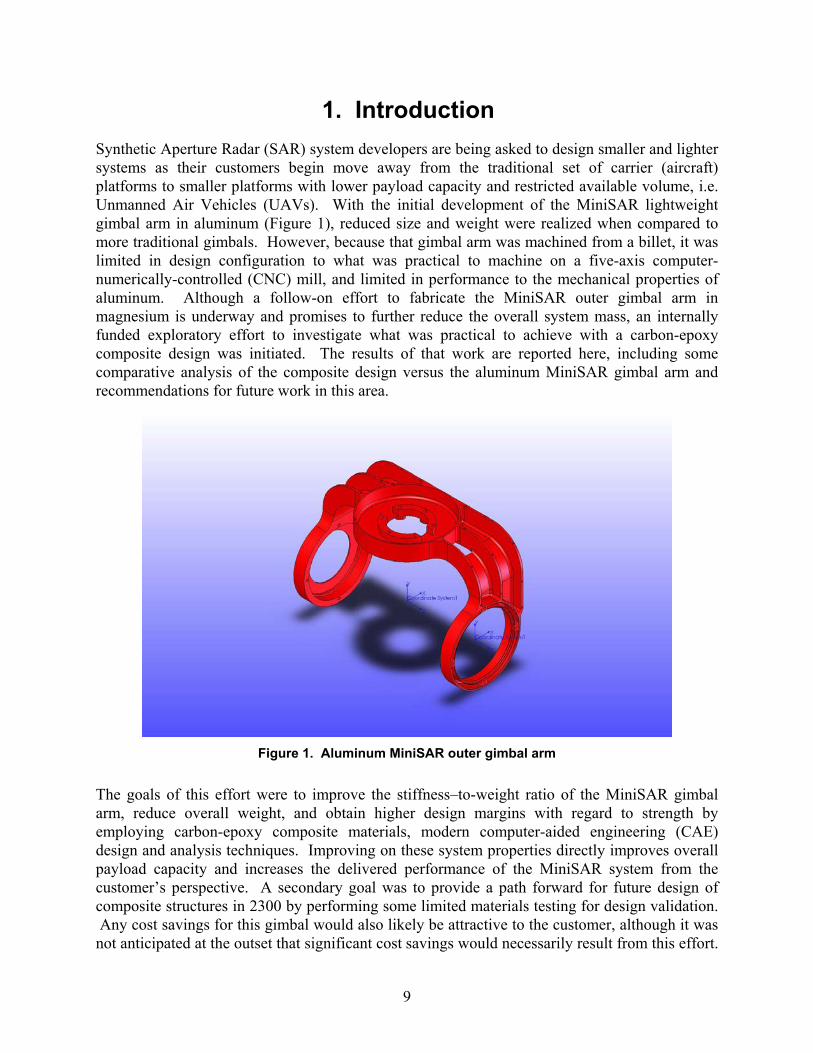
1. Introduction Synthetic Aperture Radar (SAR) system developers are being asked to design smaller and lighter systems as their customers begin move away from the traditional set of carrier (aircraft) platforms to smaller platforms with lower payload capacity and restricted available volume, i.e. Unmanned Air Vehicles (UAVs). With the initial development of the MiniSAR lightweight gimbal arm in aluminum (Figure 1), reduced size and weight were realized when compared to more traditional gimbals. However, because that gimbal arm was machined from a billet, it was limited in design configuration to what was practical to machine on a five-axis computer-numerically-controlled (CNC) mill, and limited in performance to the mechanical properties of aluminum. Although a follow-on effort to fabricate the MiniSAR outer gimbal arm in magnesium is underway and promises to further reduce the overall system mass, an internally funded exploratory effort to investigate what was practical to achieve with a carbon-epoxy composite design was initiated. The results of that work are reported here, including some comparative analysis of the composite design versus the aluminum MiniSAR gimbal arm and recommendations for future work in this area.
Figure 1. Aluminum MiniSAR outer gimbal arm
The goals of this effort were to improve the stiffness�to-weight ratio of the MiniSAR gimbal arm, reduce overall weight, and obtain higher design margins with regard to strength by employing carbon-epoxy composite materials, modern computer-aided engineering (CAE) design and analysis techniques. Improving on these system properties directly improves overall payload capacity and increases the delivered performance of the MiniSAR system from the customer�s perspective. A secondary goal was to provide a path forward for future design of composite structures in 2300 by performing some limited materials testing for design validation. Any cost savings for this gimbal would also likely be attractive to the customer, although it was not anticipated at the outset that significant cost savings would necessarily result from this effort.
10
However, it should be noted that once a gimbal arm design is proven and is ready for production using the typical wet-layup-molding technique, the reusable molds have already been produced and verified for the prototype unit, so that there is some potential for unit cost savings in producing multiple units from the original set of molds.
In an effort to increase stiffness, strength, and reduce weight, we investigated composite carbon fiber (CF) as a material for gimbal arm manufacture. Today, CF is used in a variety of industries for various part applications. Reasons for using CF are improved aesthetics and structural support. CF applications include automobile dash panels, motorcycle wheel rims, aircraft fuselage components (Figures 3 � 5), airfoils, bicycle fames, military armor pieces, and musical instrument protective cases. When applied as a woven cloth of individual CF, the ability of the weave (Figure 2) to stretch and lay over flat and complex curved surfaces allows it to adapt to a gimbal arm design with complex curvature; a major advantage of fiber composites that is not as easily achieved in a conventionally machined part.
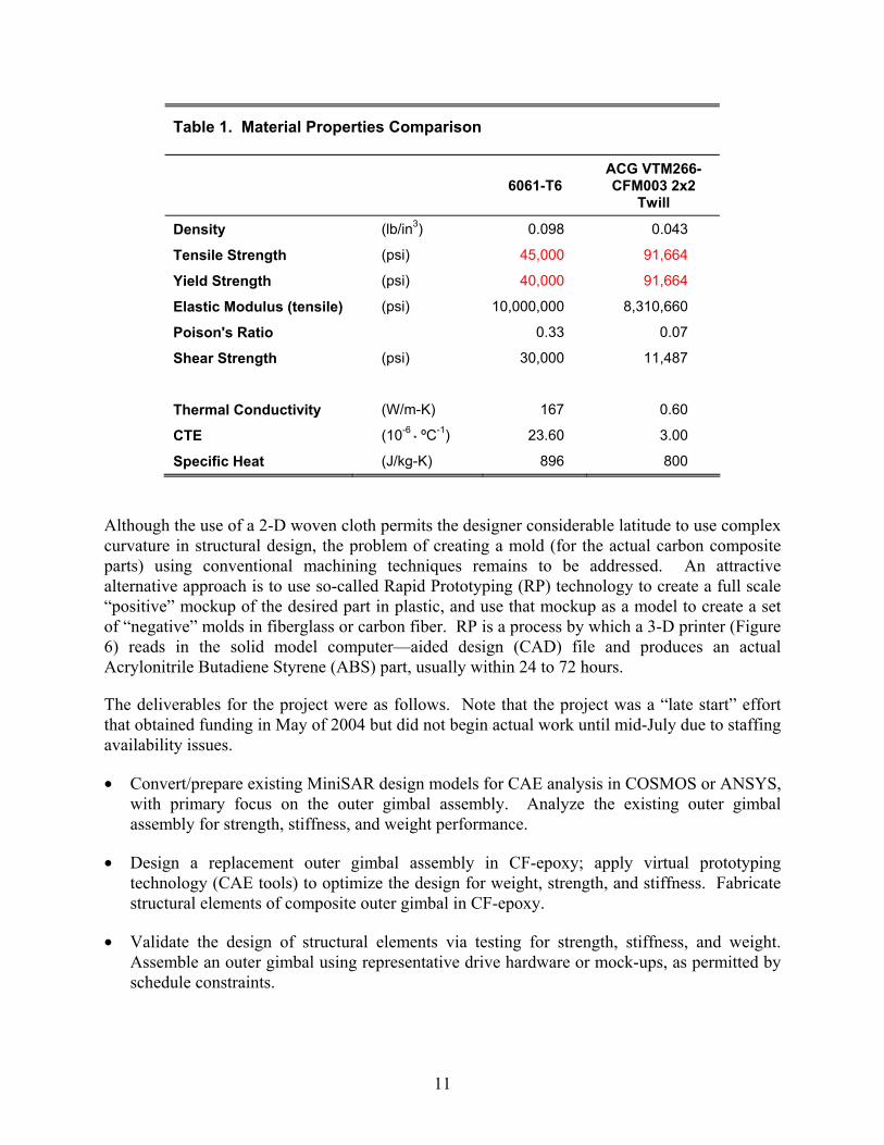
Introducing better tensile properties translates to a component having a higher Factor of Safety (FOS). Given a quick review of aluminum�s mechanical properties to that of CF (Table 1), the project�s goals appear at first glance to be achievable. Note that the mechanical properties of a CF cloth embedded in a cured epoxy matrix can be problematic to predict theoretically, and are typically measured via testing.
Although the use of a 2-D woven cloth permits the designer considerable latitude to use complex curvature in structural design, the problem of creating a mold (for the actual carbon composite parts) using conventional machining techniques remains to be addressed. An attractive alternative approach is to use so-called Rapid Prototyping (RP) technology to create a full scale �positive� mockup of the desired part in plastic, and use that mockup as a model to create a set of �negative� molds in fiberglass or carbon fiber. RP is a process by which a 3-D printer (Figure 6) reads in the solid model computer�aided design (CAD) file and produces an actual Acrylonitrile Butadiene Styrene (ABS) part, usually within 24 to 72 hours.
The deliverables for the project were as follows. Note that the project was a �late start� effort that obtained funding in May of 2004 but did not begin actual work until mid-July due to staffing availability issues.
• Convert/prepare existing MiniSAR design models for CAE analysis in COSMOS or ANSYS, with primary focus on the outer gimbal assembly. Analyze the existing outer gimbal assembly for strength, stiffness, and weight performance.
• Design a replacement outer gimbal assembly in CF-epoxy; apply virtual prototyping technology (CAE tools) to optimize the design for weight, strength, and stiffness. Fabricate structural elements of composite outer gimbal in CF-epoxy.
• Validate the design of structural elements via testing for strength, stiffness, and weight. Assemble an outer gimbal using representative drive hardware or mock-ups, as permitted by schedule constraints.
12
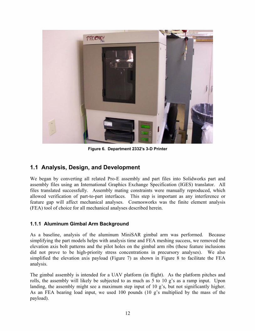
Figure 6. Department 2332's 3-D Printer
1.1 Analysis, Design, and Development
We began by converting all related Pro-E assembly and part files into Solidworks part and assembly files using an International Graphics Exchange Specification (IGES) translator. All files translated successfully. Assembly mating constraints were manually reproduced, which allowed verification of part-to-part interfaces. This step is important as any interference or feature gap will affect mechanical analyses. Cosmosworks was the finite element analysis (FEA) tool of choice for all mechanical analyses described herein.
1.1.1 Aluminum Gimbal Arm Background
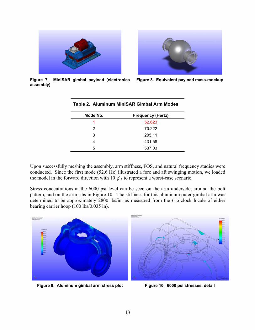
As a baseline, analysis of the aluminum MiniSAR gimbal arm was performed. Because simplifying the part models helps with analysis time and FEA meshing success, we removed the elevation axis bolt patterns and the pilot holes on the gimbal arm ribs (these feature inclusions did not prove to be high-priority stress concentrations in precursory analyses). We also simplified the elevation axis payload (Figure 7) as shown in Figure 8 to facilitate the FEA analysis.
The gimbal assembly is intended for a UAV platform (in flight). As the platform pitches and rolls, the assembly will likely be subjected to as much as 5 to 10 g�s as a ramp input. Upon landing, the assembly might see a maximum step input of 10 g�s, but not significantly higher. As an FEA bearing load input, we used 100 pounds (10 g�s multiplied by the mass of the payload).
Upon successfully meshing the assembly, arm stiffness, FOS, and natural frequency studies were conducted. Since the first mode (52.6 Hz) illustrated a fore and aft swinging motion, we loaded the model in the forward direction with 10 g�s to represent a worst-case scenario.
Stress concentrations at the 6000 psi level can be seen on the arm underside, around the bolt pattern, and on the arm ribs in Figure 10. The stiffness for this aluminum outer gimbal arm was determined to be approximately 2800 lbs/in, as measured from the 6 o�clock locale of either bearing carrier hoop (100 lbs/0.035 in).
As seen in Figure 11, the original aluminum arm has a minimum 1.5× FOS, within these same regions as expected.
Figure 11. Aluminum gimbal arm, FOS distribution
1.1.2 Composite Gimbal Arm, Development
As shown in Table 1, CF material has roughly double the tensile strength as 6061 aluminum at approximately 50% the density, whereas the Young�s modulus values are similar enough to consider them essentially equal. Most metals like aluminum can be treated as a homogeneous, isotropic material for stress analysis. However, CF weave has tows (bundles) of carbon thread where the tows are braided perpendicular to each other and woven into a continuous sheet. Each CF sheet is approximately 0.010 inches thick before cure (post-cure thickness is around 0.005-0.009 inches). To compose a part�s skin thickness, the CF sheets are alternately laid on top, and then at 45º to one another. Because of the weave in the sheet, stress analysis can be very complex. Ideally, the engineer must faithfully represent these layers in the FEA code for a truly accurate analysis result. A secondary goal of this effort was to investigate the hypothesis that the homogeneous, isotropic assumption made for metals can be made successfully for cured carbon epoxy structures if tensile test specimens within a limited range of thicknesses can be shown to behave in a linear-elastic manner for a well-defined range of stress/strain values. If true, then routinely modeling and analyzing carbon-epoxy composite structures using desktop FEA tools becomes reasonable and the routine design of such structures can become a reality.
15
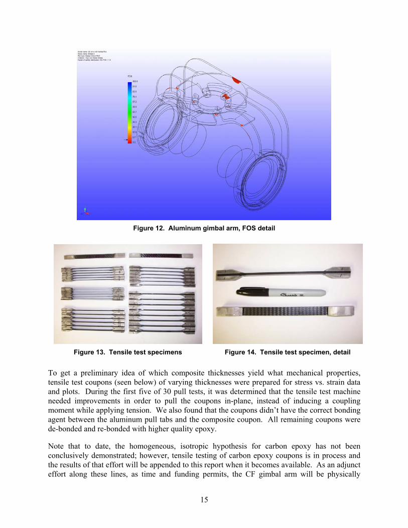
Figure 12. Aluminum gimbal arm, FOS detail
Figure 13. Tensile test specimens Figure 14. Tensile test specimen, detail
To get a preliminary idea of which composite thicknesses yield what mechanical properties, tensile test coupons (seen below) of varying thicknesses were prepared for stress vs. strain data and plots. During the first five of 30 pull tests, it was determined that the tensile test machine needed improvements in order to pull the coupons in-plane, instead of inducing a coupling moment while applying tension. We also found that the coupons didn�t have the correct bonding agent between the aluminum pull tabs and the composite coupon. All remaining coupons were de-bonded and re-bonded with higher quality epoxy.
Note that to date, the homogeneous, isotropic hypothesis for carbon epoxy has not been conclusively demonstrated; however, tensile testing of carbon epoxy coupons is in process and the results of that effort will be appended to this report when it becomes available. As an adjunct effort along these lines, as time and funding permits, the CF gimbal arm will be physically
16
stressed to determine how close the treatment of carbon-epoxy composite as a homogeneous, isotropic material is to actual performance.
Using the original arm�s data as benchmarks, CF arm design began by assuming the newer arm would be a direct, bolt-in replacement to its aluminum counterpart. Because successfully designing and fabricating carbon composite structures have in the past been as much an art as a science, a highly experienced vendor was brought into the project early in the process. This was as much to facilitate the eventual fabrication of the molds and the final parts as to learn from his experience with this material. Mr. David Lawrie of Composite Tooling Corporation provided consulting advice as to how to design using the advantages of a woven fabric and unidirectional tape. Fabrics and tapes allow the designer some unique flexibility with shaping surface features, where these features would be difficult if not impossible to create with a machining effort. For instance, the fabric makes an excellent host for a �skin thickness� design with complex curvatures.
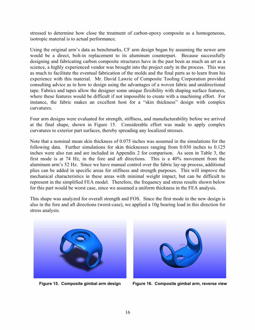
Four arm designs were evaluated for strength, stiffness, and manufacturability before we arrived at the final shape, shown in Figure 15. Considerable effort was made to apply complex curvatures to exterior part surfaces, thereby spreading any localized stresses.
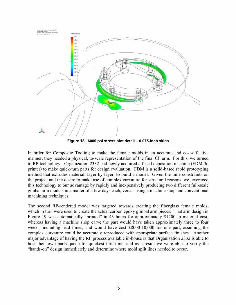
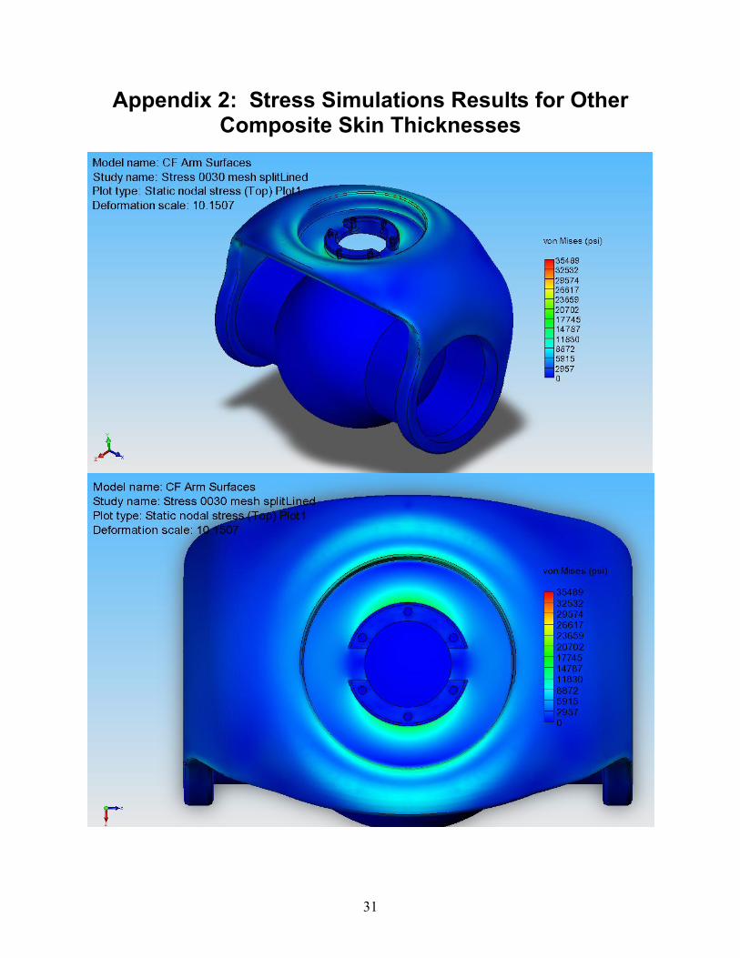
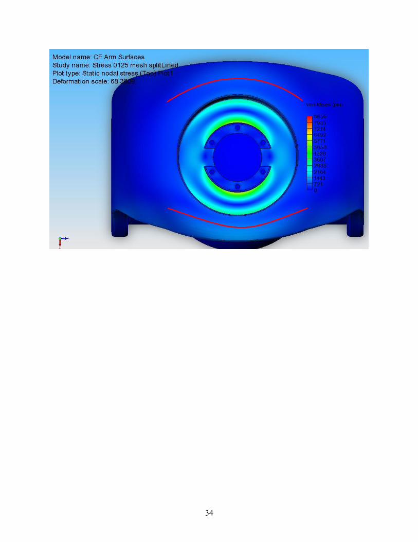
Note that a nominal mean skin thickness of 0.075 inches was assumed in the simulations for the following data. Further simulations for skin thicknesses ranging from 0.030 inches to 0.125 inches were also run and are included in Appendix 2 for comparison. As seen in Table 3, the first mode is at 74 Hz, in the fore and aft directions. This is a 40% movement from the aluminum arm�s 52 Hz. Since we have manual control over the fabric lay-up process, additional plies can be added in specific areas for stiffness and strength purposes. This will improve the mechanical characteristics in these areas with minimal weight impact, but can be difficult to represent in the simplified FEA model. Therefore, the frequency and stress results shown below for this part would be worst case, since we assumed a uniform thickness in the FEA analysis.
This shape was analyzed for overall strength and FOS. Since the first mode in the new design is also in the fore and aft directions (worst-case), we applied a 10g bearing load in this direction for stress analysis.
As shown in the figures above, stress values overall are lower than they are for the aluminum arm; a contribution of the composite fiber mechanical properties. This yields to a more advantageous 3.0 minimum FOS compared to the original design�s 1.5 localized FOS. The higher stresses are located in the azimuth-bearing bore and around its bolt circle (these features were not available for redesign as the CF part is a direct replacement for the aluminum counterpart). The 3050 lbs/in stiffness is an improvement as well.
Our consultant from Composite Tooling Corporation advised that the female mold for the part would have to be split into left, right, front, and back sections due to the design�s complex curvatures. One disadvantage to using composites in these applications is when tight tolerancing is necessary (e.g., bearing bores). Composite material doesn�t machine as well as metallics when sharp corners, female threads, or similar features are involved. The bearing bores, threaded holes, and other detail features were machined into three aluminum inserts, which are nested into the part�s composite lay-up and bonded in place during final cure.
Figure 17. Composite arm stress plot � 0.075-inch skins
In order for Composite Tooling to make the female molds in an accurate and cost-effective manner, they needed a physical, to-scale representation of the final CF arm. For this, we turned to RP technology. Organization 2332 had newly acquired a fused deposition machine (FDM 3d printer) to make quick-turn parts for design evaluation. FDM is a solid-based rapid prototyping method that extrudes material, layer-by-layer, to build a model. Given the time constraints on the project and the desire to make use of complex curvature for structural reasons, we leveraged this technology to our advantage by rapidly and inexpensively producing two different full-scale gimbal arm models in a matter of a few days each, versus using a machine shop and conventional machining techniques.
The second RP-rendered model was targeted towards creating the fiberglass female molds, which in turn were used to create the actual carbon epoxy gimbal arm pieces. That arm design in Figure 19 was automatically �printed� in 43 hours for approximately $1200 in material cost, whereas having a machine shop carve the part would have taken approximately three to four weeks, including lead times, and would have cost $8000-10,000 for one part, assuming the complex curvature could be accurately reproduced with appropriate surface finishes. Another major advantage of having the RP process available in-house is that Organization 2332 is able to host their own parts queue for quickest turn-time, and as a result we were able to verify the �hands-on� design immediately and determine where mold split lines needed to occur.
19
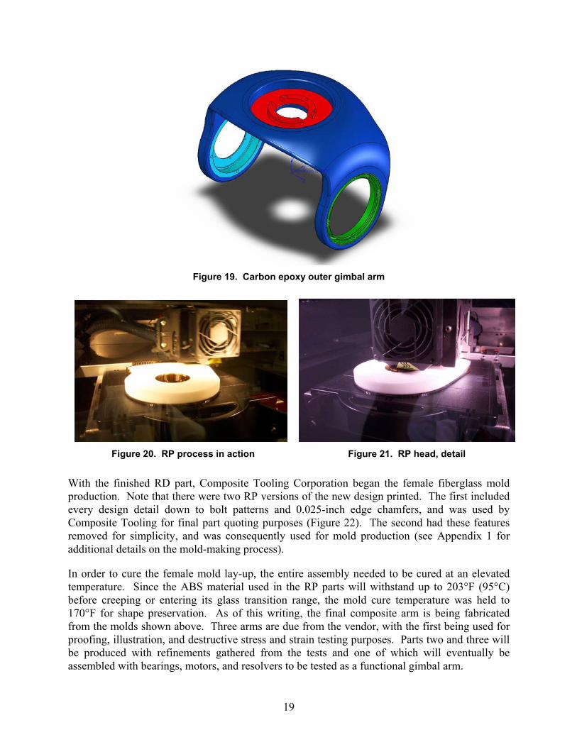
Figure 19. Carbon epoxy outer gimbal arm
Figure 20. RP process in action Figure 21. RP head, detail
With the finished RD part, Composite Tooling Corporation began the female fiberglass mold production. Note that there were two RP versions of the new design printed. The first included every design detail down to bolt patterns and 0.025-inch edge chamfers, and was used by Composite Tooling for final part quoting purposes (Figure 22). The second had these features removed for simplicity, and was consequently used for mold production (see Appendix 1 for additional details on the mold-making process).
In order to cure the female mold lay-up, the entire assembly needed to be cured at an elevated temperature. Since the ABS material used in the RP parts will withstand up to 203°F (95°C) before creeping or entering its glass transition range, the mold cure temperature was held to 170°F for shape preservation. As of this writing, the final composite arm is being fabricated from the molds shown above. Three arms are due from the vendor, with the first being used for proofing, illustration, and destructive stress and strain testing purposes. Parts two and three will be produced with refinements gathered from the tests and one of which will eventually be assembled with bearings, motors, and resolvers to be tested as a functional gimbal arm.
20
Figure 22. Rapid Prototype Gimbal Arm, version 1
Figure 23. RP part ready to be used for female mold fabrication
Figure 24. Creating the female mold in fiberglass weave
21
Figure 25. Finished Lower Female Mold with RP male part fitted
22
This page intentionally left blank.
23
2. Results and Conclusions The CAD file conversion process from Pro-Engineer to Solidworks was a success, although there is no requirement that the design and analysis process be conducted on any particular CAD/CAE toolset. The process we used in Solidworks and Cosmosworks works just as well using ProE and ANSYS or Mechanica; however, we chose the former purely for convenience.
Fabrication of the first composite gimbal arm was completed by the first week of October 2004. A total of three completed composite arms were ordered and will be eventually delivered. The first of the three will be used to validate the FEA predictions of deflection and strength, and will then be tested to failure to learn more about the structure�s real properties. The better of the other two arms will be used for full assembly mockup. Estimated cost for producing the current fiberglass molds is approximately $10K, and if new molds were to be required in the future due to design changes, that would be a reasonable order-of-magnitude estimate. Producing additional composite outer gimbal arms from the existing molds are estimated by the vendor to cost approximately $3K each, regardless of the quantity ordered.
Table 4 presents the analysis results of the existing aluminum MiniSAR gimbal arm and the new CF-epoxy composite design. The composite part has better predicted tensile and yield characteristics than its aluminum counterpart. As a result, it also has a higher FOS margin, higher stiffness, and generally higher natural frequencies, depending on the skin thickness assumed. The stress plots of both arms illustrate that the composite arm experiences about half of the peak stresses in critical areas compared to the aluminum arm. These lower stresses are also distributed over a larger area versus a concentrated spot.
Establishing the lay-up schedule for a complex composite part is a learning process, and as a result, the first prototype arm is not optimized for weight or strength. Because the first prototype arm has a mean skin thickness of nearly 0.125 inches with generous material overlap in areas of high predicted stress rather than the intended design skin thickness of 0.075 inches, the weight of the first composite arm produced is higher than both the aluminum arm and the predicted values for the prototype composite arms with thinner skins shown in Table 4. However, we believe we can trade off the additional FOS margin for mass in the second and third prototype arms (yet to be fabricated) and achieve the predicted performance by judicious application of additional carbon material in selective areas of high stress. We can potentially reduce the design skin thickness by as much as 30% in many areas to reduce weight, which would result in a composite arm weighing approximately 0.65 lbs the machined aluminum azimuth bearing mount but not the machined aluminum elevation bearing mounts. Because two machined aluminum elevation bearing mounts significantly (0.20 lb) add to the total weight of the gimbal arm, we are investigating alternative materials, including a precision fabricated carbon epoxy fitting that would further reduce weight without sacrificing functionality.
As mentioned earlier, tensile test coupons are being reassembled for evaluation. The test lab has updated their equipment to subject the coupons to true in-plane tensile forces. The tensile tests will be completed in October and the data will be appended to this report. Again, this data will aid in confirming global, mechanical properties treatment in the FEA analysis.
24
Table 4. Comparative Results
Item 6061-T6 Aluminum
0.075-Inch Carbon-Epoxy
0.030-Inch Carbon-Epoxy
Weight 1.180 lbs 0.96 lbs* 0.65 lbs*
Minimum Factor Of Safety 1.5 3* 2.8*
Stiffness @ extreme deformation (k = F/x)
2800 lbf/in 3050* lbf/in 1100* lbf/in
First modal frequency 52.63 Hz 74.32 Hz* 46.9 Hz*
Second modal frequency 70.22 Hz 104.85 Hz* 71.9 Hz*
Third modal frequency 205.1 Hz 258.13 Hz* 139.5 Hz* * Predicted value
Although this project was on a tight timeline, beginning work in mid-July and completing the initial prototype fabrication in early October, invaluable lessons were learned regarding the applicability of desktop FEA tools and RP technology to the practical application of composite fiber technology. Based on results to date, we believe the combination of 3D solid modeling, RP fabrication, and CF-epoxy composite material technologies can offer previously unconsidered alternatives for mechanical structure design at very competitive cost and weight factors. Further lessons will be learned and the design will continue to improve as we test and refine the current design to optimize it for weight and strength.
25
Appendix 1: Miscellaneous Pictures of the Composite Arm Mold Manufacturing Process
Using the Rapid Prototype (RP) part to fashion the female molds.
Wet lay-up of epoxy resin applied to male part.
26
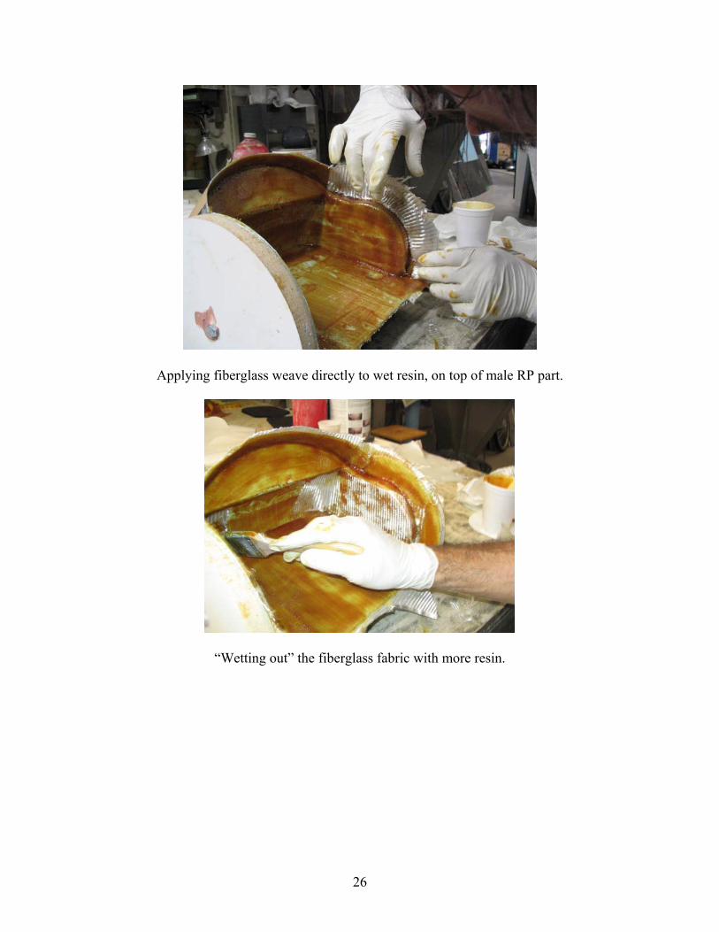
Applying fiberglass weave directly to wet resin, on top of male RP part.
�Wetting out� the fiberglass fabric with more resin.
27
Cured female fiberglass mold on male RP part.
Female mold separated from RP part.
28
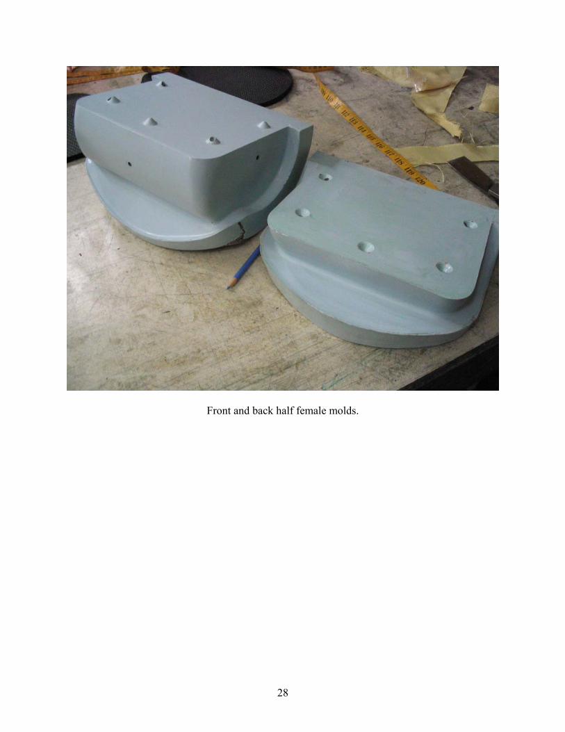
Front and back half female molds.
29
Assembled front and back halves ready for final male part layup.
30
This page intentionally left blank.
31
Appendix 2: Stress Simulations Results for Other Composite Skin Thicknesses
32
33
34
35
DISTRIBUTION: 1 MS 0503 D. Plummer, 2330 5 MS 1360 M. Winscott, 2332 1 MS 0519 A. Doerry, 2342 1 MS 0501 M. Dowdican, 2337 1 MS 0519 R. Graham, 2342 1 MS 0519 W. Hensley, 2342 1 MS 0501 T. Kim, 2338 5 MS 0501 P. Klarer, 2332 1 MS 0501 M. Martinez, 2334 1 MS 0972 A. Muyshondt, 5723 1 MS 0529 G. Sloan, 2345 1 MS 0529 K. Sorensen, 2345 1 MS 0503 D. Tolsch, 2339 1 MS 9018 Central Technical Files, 8945-1 2 MS 0899 Technical Library, 9616 5 MS 0501 M. Craig, 2332