158
Manual for Implementation of Sustainability Schemes Under National Rural Drinking Water Programme Ministry of Drinking Water and Sanitation Govt. of India

Manual for Implementation of Sustainability Schemes
Under National Rural Drinking Water Programme
Ministry of Drinking Water and Sanitation
Govt. of India
2
INDEX MANUAL FOR IMPLEMENTATION OF SUSTAINABILITY COMPONENT OF
NATIONAL RURAL DRINKING WATER PROGRAMME
1 Background 7 2 Approach 9 2.1 Introduction 9 2.2 Implementation mechanism 10 3 Elements of Sustainability
11
4 Parameters to be studied for Ensuring Source Sustainability
12
5 Suggestive List of Ground, Surface and Roof-water Harvesting Systems/ Structures to improve rural drinking water supply
14
6 Funding, executing mechanism, and eligibility Criteria for Funding under Sustainability Component 6.1 Allocation 6.2 Funding and executing mechanism 6.3 Eligibility Criteria
16
16 16 16
7 Village Water Security plan for sustainability 17 7.1 Water security survey. 17 7.1.1 Administrative measures 18 7.1.2 Technical Surveys, Data Collection, integration,
interpretation, and analysis 18
7.2 Training and awareness generation 20 7.3 Final Plan for Village water Security 20 7.4 Monitoring mechanism 20 8 Selection of sustainability structures & locations 21 8.1 Identification of Problem Villages 22 8.2 Field observations, criteria, tests, and selection of sustainability
structures 23
8.2.1 Rainfall pattern of the area 24 8.2.2 Drainage Pattern and drainage order of the area. 25 8.2.3 Geomorphology of the area. 27 8.2.4 Hydrogeology of the area 32 8.2.5 General gradient 25 8.2.6 Type of Source 33 8.3 Sustainability Structures for groundwater based sources 35
3
8.4 Artificial Recharge Techniques 36 8.4.1 Surface Spreading Techniques 38 8.4.1.1 Flooding
8.4.1.2 Ditch and Furrows method 8.4.1.3 Recharge Basins
8.4.2 Runoff Conservation Structures
39 39 41 42
8.4.2.1 Bench Terracing 43 8.4.2.2 Contour Bunds
8.4.2.2.1 Spacing of Bunds 8.4.2.2.2 Cross Section of Contour Bunds 8.4.2.2.3 Deviation Freedom 8.4.2.3 Contour Trenches
8.4.2.4 Gully Plugs, Nalah Bunds and Check Dams
8.4.2.5 Percolation Tanks
8.4.2.5.1 Site Selection Criteria
8.4.2.5.2 Investigations Required
8.4.2.5.3 Engineering Aspects
8.4.2.6. Modification of Village Tanks as Recharge Structures
8.4.3 Sustainability structures for Surface Water based sources
8.4.3.1 Ooranis
8.4.2.Stream Channel Modification / Augmentation
8.4.4 Subsurface Techniques
8.4.4.1 Injection Wells or Recharge Wells
8.4.3.2 Gravity Head Recharge Wells
8.4.3.3 Recharge Pits and Shafts
8.5 Indirect Methods
8.5.1 Induced Recharge
8.5.1.1 Design Guidelines
8.5.2 Aquifer Modification Techniques
8.5.2.1 Borewell Blasting Technique
8.5.2.2 Hydrofracturing
8.6 Combination Methods
8.7 Ground Water Conservation Techniques
8.7.1 Sub-SurfaceDykes/Ground Water Dams / Underground ‘Bandharas’
45 46 47 48 41 50 44 51 52 54 56 56 69 71 71 66 76 76 77 77 81 83
88 88 89 90 90 91
95 95
95
4
8.7.1.1 Site Characteristics and Design Guidelines
8.8. Suitability of Artificial Recharge Structures under Combination of
Factors
9. Rooftop Rainwater Harvesting 9.1 Concept of Roof Top Rainwater Harvesting
9.2 Components of Roof Top Rainwater Harvesting System
9.2.1 Roof Catchment
9.2.2 Drain Pipes
9.2.3 Gutters
9.2.4 Downtake Pipe
9.2.5 First Flush Pipe
9.2.6 Filtration of water
9.2.6.1 Charcoal water filter
9.2.6.2 Sand filters
9.2.6.3 PVC Tube filter
9.2.7 Storage Tank
9.2.7.1 Size of Storage Tanks for water stressed Areas
9.2.7.2 Size of Storage Tank for areas having regular water supply
9.2.8 Collection Sump
9.2.9 Pump Unit
9.3 Data Requirements for Planning Rainwater Harvesting Systems
9.3.1 Amount of Rainfall (mm/year)
9.3.2 Rainfall Distribution
9.3.3 Intensity of Rainfall
9.3.4 Surface Area
9.3.5 Storage Capacity
9.3.6 Daily Demand
9.3.7 Number of Users
9.3.8 Cost
9.3.9 Alternative Water Sources
95
100
104
104 106 106 107 107 108 108 108 110 111 111 112 112 113 113
114 117
117 118 118 118
118 118
118 119 119
119 119 119 104
5
9.3.10 Water management Strategy
9.4 Feasibility of Roof Top Rainwater Harvesting Systems in Rural Area
9.5 Technical Suitability
9.5.1 Existing Water Sources
9.5.2 Roof Catchment
9.5.3 Rainfall
9.5.4 Space
9.6 Social Acceptance
9.6.1 Acceptance of Roof Water as Drinking Water
9.6.2 Willingness of Households to Participate
9.6.3 Traditional Practices of Roof Water Collection
9.7 Water Quality and Health
9.7.1 Bacteriological Water Quality
9.7.2 Insect Vectors
9.7.3 Water Treatment
9.7.4 Analysis of Water Samples
9.7.5 Disinfecting Water
9.8 Ready Reckoner for Design of Roof Top Rainwater Harvesting Systems
9.9 Computation of Flow through Half Section Gutters
9.10 Data Requirements for Design of Roof Top Rainwater Harvesting
Systems
9.11 Design Example
10. Impact Assessment 10.1 Monitoring of Recharge Structures
10.2 Water Level Monitoring
10.3 Water Quality Monitoring
10.3.1 Evaluation of Existing Water Quality Data
10.3.2 Pre-operational Monitoring
10.3.3 Operational Monitoring
10.3.4 Post-operational Monitoring
119 119 120 121
121 121 122 106 106 122 122 123 123
124 124 125
125 126 126 110 127 128
129 112 131
134
134
136 137 137 138 138 140
6
11. Sustainability measures based on New and Renewable energy
Annexure-1 Case Studies
Case Study-1 Artificial Recharge to Ground Water through Check Dam cum
Ground Water Dam , Himachal Pradesh
Case Study-2 Demonstrative Project on Artificial Recharge to Ground Water
taken up during 2009-12
Annexure-2 References used in this manual, suggested readings
for Design elements for sustainability structures, and sources
recommended for further readings.
Annexure-3 List of Abbreviations used in the Manual
141
142
142
145
157
158
7
1 Background The maintenance of desired quantity and acceptable quality standard of water supply
services throughout the design life of the water supply systems may be defined as
sustainability. The system as well as the water supply source must fulfill these criteria.
The sustainability is with reference to:
• Source – quantity and quality
• System – infrastructures
Factors affecting sustainability of water sources:
• The depletion or lowering of water levels in groundwater and surface water
sources
• Change/degradation of water quality due to over drawls or contamination by
domestic/industrial wastes/ waste water
For ensuring sustainability of the systems, steps were initiated in 1999 to
institutionalize community participation in the implementation of rural drinking water
supply scheme by incorporating the following three basic principles:
I. Adoption of a demand-driven responsive and adaptable approach based on
empowerment of villagers to ensure their full participation in the project
through a decision making role in the choice of scheme design, control of
finances and management arrangements.
II. Increasing role of government for empowering user groups/gram panchayats
for sustainable management of drinking water assets and integrated water
management and conservation.
III. Partial capital cost sharing either in cash or kind or both and 100 per cent
responsibility of Operation and Maintenance by end-users.
The revised National Rural Drinking Water Programme (NRDWP) Guidelines issued by
Rajiv Gandhi National Drinking Water Mission, Department of Drinking Water &
Sanitation has focus on adequate water supply in quantity and quality, to each rural
household on a sustainable basis.

8
Despite the impressive coverage of provision of safe drinking water facilities in the
rural areas, there is considerable gap between infrastructure created and service
available at the household level. The issue of sustainability of source and system for
ensuring supply of potable water are cited as the two major constraints in achieving
the national goal of providing drinking water to all rural population. This is primarily
due to rapid depletion of ground water because of over exploitation and lack of
community involvement in operation and maintenance of rural water supply schemes.
The Guidelines on sustainability as outlined in the “Framework for Implementation” of
NRDWP are provided in the next sections to explicate the understanding and thrust of
the MoDWS on Sustainability component and its implementation.
9
2 Approach 2.1 Introduction The term “Sustainable Development” was defined by Bruntland in 1987 as
development that meets the needs of the present without compromising the ability of future
generations to meet their own needs. Groundwater used for freshwater drinking supplies can be
easily overexploited by other competing users like irrigation, industry, etc.
When this happens it can become contaminated with salt water, fluoride or other geogenic
ontaminants which makes it unsuitable for use. Water available in rivers and lakes is
sometimes polluted, making it harmful to plants, animals and people. Sustainability and safe
sanitation practices are the forerunner for safe drinking water supply. The paradigm shift in
the new framework is to move towards achieving universal access to rural population for
having safe and sustainable drinking water supply rather than a mere coverage of habitations,
the latter not necessarily speaking about equity and vulnerability issues. Therefore the aim is
to work at achieving household level drinking water security, which shall obviously ensure
universal access.
History stands witness to man’s use of varied forms of technology and science, ranging
from the simplest to the most complicated, for storing and extracting water. India has a
particularly strong tradition of water harvesting – communities have met their minimum water
requirements effectively by collecting rainwater locally, diverting and storing water from local
streams and springs and tapping sub-surface water. However, these traditional technologies
and methods have fallen prey to inattention and ignorance over time, and need to be revived
and rejuvenated. On the other hand are the most modern, state-of-the-art technologies and
practices which could make a lot of difference in these water-stressed times. This approach
offers today’s water managers a range of choices which will enable them to make their
own water security plans in an effective manner – by taking from the best practices of
both the worlds and adopting them viably for best results.
Traditional structures such as the tankas and khadins of Rajasthan, baoris (step-wells)
of western India, the ooranis, cheruvus and temple tanks of south India, and the bamboo split
pipe harvesting method practised in the north-east still serve as lifelines for local people.
Communities can combine and converge this knowledge with modern technologies and
scientific tools such as satellite imaging. Emphasizing on the urgent need for rainwater
harvesting, replenishing and restoring existing surface water bodies and creating new ones,
and recharging groundwater, this segment urges practitioners to think beyond the
conventional and look for innovative solutions.

10
2.2 Implementation mechanism
The 20% allocation for Sustainability- which is on a 100% Central share basis will be used
exclusively to achieve drinking water security by providing specific sustainability components
for sources and systems with major emphasis on tribal areas, water quality affected areas,
Over-exploited and Critical areas as specified by CGWB and any other area the State
Government has identified as difficult and water stressed area. Basic Swajaldhara principles of
community and PRI based planning, implementation; management of the schemes is to be
adopted.
For operation and management of schemes the Central Finance Commission funds are to be
utilized. Under this component preparation of village water security plan is mandatory. For
taking up sustainability projects it is to be ensured that the existing and proposed rural
drinking water sources are directly recharged and for that detailed manuals on “Mobilising
Technology for Sustainability”, “Bringing Sustainability of Drinking Water System” and
“Convergence of sustainability projects” (web site: http://ddws.gov.in under icon Publication
2007-08) issued by The Department of Drinking Water Supply, Government of India may be
referred for planning, design and implementation of sustainability projects under NRDWP. The
sustainability activities should be carried out with the stress on following key considerations:
• Shift focus from dependence on single source to multiple sources of drinking water
• Water demand and budgeting for ensuring household level drinking water security
• Reject management issues to be addressed properly so that the contaminants do not
re-enter into water, environment or food.
11
3 Elements of Sustainability
Source Sustainability: Ensuring availability of safe drinking water in adequate quantity
throughout the year
System Sustainability: Optimizing the cost of production of water, devising proper protocol
for O&M, building capacity of PRIs and awareness generation
Financial Sustainability: Proper utilization of Finance Commission and O&M funds under
NRDWP guidelines and recovering at least 50% cost through flexible methods devised by the
local self government and improving energy efficiency
Social and environmental Sustainability
Proper reject management and involvement of all key stakeholders Sustainability of drinking
water sources and schemes is a process which facilitates the existing/new drinking water
supply projects to provide safe drinking water in adequate quantity, even during distress
periods, duly addressing equity, gender, vulnerability, convenience and consumer preference
issues, through conjunctive use of groundwater, surface water and roof-water harvesting.. The
main aim of providing sustainability of drinking water schemes is to ensure that such schemes
do not slip back from universal access of safe drinking water to the community throughout the
design period of the schemes.
Any recharging structure meant for overall management of water resources and that does not
directly recharge drinking water sources; is not eligible for funding under the Sustainability
component of this Programme.
The basic principles of sustainability are:-
• Conjunctive use of water defined as judicious use of ground water, surface water and
roof-water as per drinking water demand and availability, seasonally or monthly.
• Recharge of groundwater aquifers during monsoon. This could even dilute
the contaminants considerably over a period of time. Many recharge structures
provide both for groundwater recharge and surface water availability.
• Conservation of Surface water Sources

12
• Promote Rainwater /Dew/ Snow harvesting in a big way especially for scattered
habitations.
• Revive traditional water harvesting structures, and village ponds into better functional
systems in providing safe drinking water.
• Use of efficient, new and renewable energy sources for pumping /in situ treatment like
solar disinfection, solar desalination, etc.
• Promote Recycling and Reuse of water
13
4 Parameters to be studied for Ensuring Source
Sustainability The following parameters are considered important and are suggested to be
considered for planning, designing, and implementaito of sustainability schemes for
drinking water sources.
• Local wisdom
• Rainfall pattern (monthly) – total, intensity, number of rainy days, hydrograph
• Rock type, Aquifer, and Groundwater status
• Water Resource Availability
• Evaporation, seepage and conveyance losses
• Soil porosity and permeability
• Overall Water budgeting for ensuring household drinking water security
• Suitability of locally available material
• Use of HGM maps based on satellite data and desirable geophysical investigations
• Level of community participation
• Existing water harvesting structures and their functionality
• Water management options for emergent situations
• Existing water saving , energy efficient practices
• Catchment Area
• Variation in availability of water at source
14
5 Suggestive List of Ground, Surface and Roof-water
Harvesting Systems/ Structures to improve rural
drinking water supply A suggestive list of systems and structures to improve Sustainability of rural drinking
water supply is given below, but this is not an all inclusive list and other relevant
structures that help improve the sustainability of rural water supply source may be
taken up as per local site conditions.
• Use of flood water for recharge
• Gully plugs
• Recharge Pit
• Contour trench/bund
• Semi-circular trenches on slopes
• Check dam/Nala bund
• Percolation pond/tank
• Sub-surface dyke
• Injection well
• Recharge shaft
• Recharge well/Dug well with radial recharging systems
• Point source recharging systems
• Recharging through sand dunes – coastal/ desert
• Levees – for retaining the flash run-off
• Infiltration gallery
• Ooranis or scientifically developed village ponds with in situ filtration and collection
system
• Roof water harvesting for communities, community structures like schools,
anganwadis, GP office, and other Government buildings.
• Snow Dam, Dew Harvesting
• Traditional water harvesting structures
From the above list the following works may be taken up under Sustainability component of
NRDWP and the balance works may be taken up under other related programmes viz.,
MGNREGS (Department of Rural Development, GoI), National Afforestation Programme

15
(Ministry of Environment and Forest), National Project for Repair, Restoration and Renovation
of Water Bodies (Ministry of Water Resources, GoI), Integrated Watershed Management
Programme (Dept of Land Resources, Ministry of Rural Development, GoI), etc.
• Roof water harvesting for community, community structures like schools, anganwadis,
GP office, hostels, health centres, hospitals, and other Government buildings.
• Ooranis, or scientifically developed village ponds with in situ filtration and collection
system
• Check dams
• Material component of Percolation tanks
• Sub-surface dyke
• Point source recharging systems (defunct borewells and abandoned dugwells)
• Infiltration well with Collector well
• Infiltration gallery
• Hydro-fracturing
The technologies mentioned above are suggestive in nature. The State Governments may like
to adopt appropriate structures depending upon the local hydro-geomorphological conditions
suitable to rural drinking water schemes.

16
6 Funding, executing mechanism, and eligibility
Criteria for Funding under Sustainability Component 6.1 Allocation : As per NRDWP guidelines, the allocation for Sustainability component is
limited to 20% on a 100% grant–in aid basis.
6.2 Funding and executing mechanism: The allocation for Sustainability will be used
exclusively to achieve drinking water security by adopting conjunctive use of surface water,
rain water and ground water and construction of water recharging structures with major
emphasis on water quality affected areas, overexploited, critical and semi-critical areas as
specified by CGWB, and any other area that the State Government has identified as water
stressed area. Basic Swajaldhara principles of community and PRI based planning,
implementation and management of the schemes are to be adopted. Under this component
preparation of Village Water Security Plan will be necessary. Guidelines for planning and
implementation of Sustainability projects at Annexure II of the NRDWP are to be followed for
execution.
6.3 Eligibility Criteria
• Sustainability structures should be taken up on priority in over-exploited, critical and
semi-critical blocks and in quality affected habitations.
• Labour cost of any recharging system/ surface water impounding structures should be
met from Mahatma Gandhi National Rural Employment Guarantee Scheme
(MGNREGS)/Integrated Watershed Management Programme funds, as far as possible.
• Desilting of ponds to be done only with MGNREGS funds
• Only material component of conversion of existing village ponds into recharge/
collection structure should be funded under this component.
• Capital cost component of roof-water harvesting structure should be a simple PVC
gutter, a simple filter, first flush facility, tap and adopting preferably ferro-cement/PVC
tanks, wherever feasible. Capacities to be designed on volume demand and available
Rainwater.
• All proposals with prior scientific database to be vetted by the State Technical Agency
involving Technical Experts and approval by the SLSSC.
• Cost of constructing roof of the house of any nature for roof-water harvesting is not
admissible under the Sustainability component.
• Sustainability component of the drinking water supply systems should be such that it is
easy to operate and maintain by the community/Gram Panchayat/Water User group.
17
7 Village Water Security plan for sustainability
The revised National Rural Drinking Water Programme (NRDWP) Guidelines 2009-
2012 issued by Rajiv Gandhi National Drinking Water Mission, Department of Drinking
Water Supply has shifted the focus from ‘source development and installation of water
supply system for providing drinking water supply to rural household’ to focus on
development of ‘village security plan’ which also includes village safety plan before
taking up planning & installation of water supply system to ensure provision of safe
and adequate water supply to each rural household at a convenient location on a
sustainable basis.
Village water security plan is a very important aspect of sustainability measures. The
implementation of village water security plan ensures sustainability of the Drinking
Water sources by optimisation of the available resources and schemes vis-à-vis
demand side management at household and village institutions level.
7.1 Water security survey.
The sequence of activities or steps used will be as follows:
Ø Problem identification
Ø Problem analysis
Ø Planning for solutions
Ø Selecting options by adopting appropriate sustainability structures
Ø Finalizing options with respect to capital, and operation and
maintenance cost.
The activities to be carried out for water security survey can be grouped into two
broad categories:
• Administrative Measures, and
• Technical Surveys and Studies
18
7.1.1 Administrative measures
• Develop State specific guidelines, formats for carrying out survey
• Procurement of GPS and training of JEs/AEs for carrying out survey, data
management and preparation of DPR on sustainability structures
• Identification of number of surveyors, supervisors and train them by experts on
water security survey.
• Identification of NGO partner and VWSC members for carrying out village-
source-wise water quality sample testing.
• Capacity building of all facilitators, on water sample collection, and GPS survey.
• District/Block level consultation with stakeholders
• Block level workshop / consultation with stakeholders
7.1.2 Technical Surveys, Data Collection, integration, interpretation, and analysis
• General information about water availability and present status
o Meeting with Panchayat Pradhan and officials and briefing about the Water
Security Plan and collection of the following information:
Ø Demographic profile of the village
Ø Physical features of the village
Ø Details of existing water sources and their water quality testing
Ø Water Demand assessment for individual village through by means of
House Hold survey.
• Technical Details
Ø Location with latitude and longitude of all water sources, existing
sustainability structures, and particularly all drinking water sources
preferably with GPS or other advanced tracking system.
Ø Log charts of the bore-wells including yield of the bore well.
Ø Design of the well and pre and post monsoon Static Water Levels.
Ø Type of rig used.
• Water Quality Analysis
Ø One of the important components of the ‘water security plan’ from the
perspective of drinking water supply is ‘water safety plan, which deals
19
with identification of a water quality problem with water safety
solution.
Ø It includes both water quality testing and sanitary inspection,
identification, and evaluation of risks to determine appropriate control
measures. It is a quality assurance tool that ensures protection of the
water quality from the catchment to the consumer.
o GP facilitators to collect samples from all the public drinking water
sources in the villages and send them to water testing laboratories
o GP shall also carry out sanitary inspection
o All the water quality parameters indicated in NRDWP guideline needs
to be tested.
o Results to be shared with PRI’s.
• Preparation of maps
o Village level map: After having completed the Village level Survey and
100% water quality testing, village by village, next step is to prepare
a Village Map, showing the locations of Safe and Unsafe water sources
and important landmarks such as schools, PHC, ICDS etc., shall be
prepared with the help of technical agency.
o Block & District Level map: After completion of the village level maps
a consolidated Block level map capturing all details of water supply
schemes need to be prepared. The map should clearly indicate detail
of all drinking water sources and system(s). It should also indicate
attributed data viz., water quality affected areas, annual pre and post
monsoon ground water fluctuation of all borewells/handpumps and
locations of all drinking water source.
o These maps should be integrated with available
Hydrogeomorphological groundwater Prospect maps for the
particular area for which the sustainability plan is being prepared.
• The team involving communities along with VWSC members/ technical support
and PRIs will analyse the information gathered for identifying the present status
of village with respect to water supply, present total water availability, demand

20
of water for drinking and other purposes, gap between water requirement and
present availability of water and arriving at probable solutions in terms of
adopting sustainability structures.
• After the preparation of village level plan, the same would be consolidated and
GP level summary will be prepared. A consultation meeting will be organized
with Gram Sabha to discuss about the GP level water Security plan.
7.2 Training and awareness generation
A. Workshop
State/ District level workshop need to be held and formal communication needs to
be sent to Block level officials, [Block Development Officer, Block Medical Officer
of Health, Sub Assistant Engineer (SAE)/Junior Engineers (JE)] providing the
background information on preparation of water security plan so that they are
aware of the new activities in their area and their role and responsibilities.
B. Capacity building of facilitators:
Rural Water Supply Agency/ concerned department shall carry out the GPS survey
involving a GP level facilitator in the process of carrying out the survey. Further, at
block level, a one day training program would be organized to develop the
capacity of GP facilitators in carrying out GPS survey by experts.
7.3 Final Plan for Village water Security
Finalizing the mechanism for the management of water resource and plan for
additional water resource development and water recharging structures (surface
and ground water) inside the GP and developing the rules for sharing the O&M
cost and formulating regulation for equitable water distribution.
7.4 Monitoring mechanism
• DWSM comprising of representative from PHED, P&RD, State Ground Water
Board, Health and PRI should monitor implementation of the Village water
security plan as well as the sustainability project on a regular basis.
• DWSM should appraise the progress at regular intervals to the SWSM in this
regard.

21
8 Selection of sustainability structures & locations The selection of a particular sustainability structure for a particular location involves a
technical study of the site, but some general guidelines may be followed for selection of
a particular structure for a particular location. The sequential mechanism for
identification of overexploited villages and a systematic approach towards selection of
sustainability structures are as outlined below.
Fig 8.1 Sequential chart of activities for Sustainability structures
22
8.1 Identification of Problem Villages
Sustainability of any source depends on the availability of water. The source of water
may be groundwater or surface water. Majority of rural water supply schemes are
based on groundwater and hence to enhance the sustainability of such water supply
schemes, or point sources for water supply, Groundwater Recharge becomes
imperative, especially in case of over exploited areas. Since sustainability structures
are targeted to benefit villages/ habitations it is important to understand that how an
overexploited village can be identified. This is important from prioritising perspective
as well.
A village can be called as an over exploited village if its Groundwater withdrawal is
more than the natural recharge. From quality perspective, villages having groundwater
or surface water as source of water supply and having quality parameters not
confirming to the desired standards are also to be targeted for adapting sustainability
measures. Since village level groundwater assessment has not been done so far in the
country, there are various ways and means such as reports, field information etc. by
which the over exploited or problem villages may be identified. These overexploited/
problem villages may then be targeted for development of sustainability measures.
The overexploited villages can be identified for development of sustainability
measures by referencing the following:
1. Documents / reports published by various monitoring agencies such as
Central Groundwater Board, State Groundwater Boards, other scientific
journals and media reports. Central groundwater Board has published state
profiles for all the states of India and they are available on the internet. These
state profiles indicate the overexploited blocks in the State. Similarly CGWB has
also published District profiles for some of the Districts in various states. These
District profiles are also indicative of the problem villages which are facing
availability or quality issues.
2. HGM maps available with the department, should also be referred to identify
the overexploited villages. the low groundwater prospect areas would be
marked with Red hatching.
23
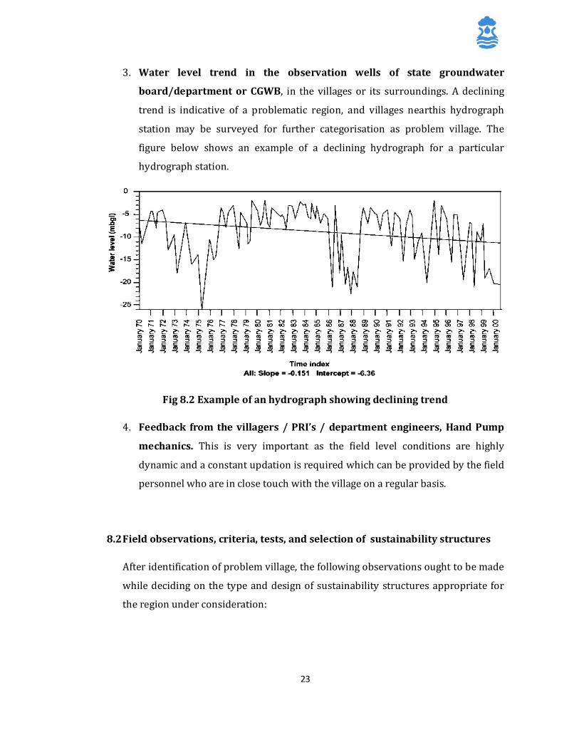
3. Water level trend in the observation wells of state groundwater
board/department or CGWB, in the villages or its surroundings. A declining
trend is indicative of a problematic region, and villages nearthis hydrograph
station may be surveyed for further categorisation as problem village. The
figure below shows an example of a declining hydrograph for a particular
hydrograph station.
Fig 8.2 Example of an hydrograph showing declining trend
4. Feedback from the villagers / PRI’s / department engineers, Hand Pump
mechanics. This is very important as the field level conditions are highly
dynamic and a constant updation is required which can be provided by the field
personnel who are in close touch with the village on a regular basis.
8.2 Field observations, criteria, tests, and selection of sustainability structures
After identification of problem village, the following observations ought to be made
while deciding on the type and design of sustainability structures appropriate for
the region under consideration:
24
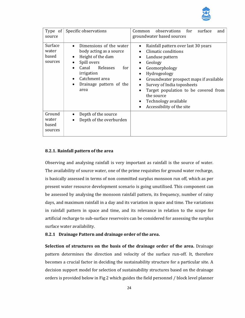
Type of source
Specific observations Common observations for surface and groundwater based sources
Surface water based sources
• Dimensions of the water body acting as a source
• Height of the dam • Spill overs • Canal Releases for
irrigation • Catchment area • Drainage pattern of the
area
• Rainfall pattern over last 30 years • Climatic conditions • Landuse pattern • Geology • Geomorphology • Hydrogeology • Groundwater prospect maps if available • Survey of India toposheets • Target population to be covered from
the source • Technology available • Accessibility of the site
Groundwater based sources
• Depth of the source • Depth of the overburden
8.2.1. Rainfall pattern of the area
Observing and analysing rainfall is very important as rainfall is the source of water.
The availability of source water, one of the prime requisites for ground water recharge,
is basically assessed in terms of non committed surplus monsoon run off, which as per
present water resource development scenario is going unutilised. This component can
be assessed by analysing the monsoon rainfall pattern, its frequency, number of rainy
days, and maximum rainfall in a day and its variation in space and time. The variations
in rainfall pattern in space and time, and its relevance in relation to the scope for
artificial recharge to sub-surface reservoirs can be considered for assessing the surplus
surface water availability.
8.2.1 Drainage Pattern and drainage order of the area.
Selection of structures on the basis of the drainage order of the area. Drainage
pattern determines the direction and velocity of the surface run-off. It, therefore
becomes a crucial factor in deciding the sustainability structure for a particular site. A
decision support model for selection of sustainability structures based on the drainage
orders is provided below in Fig 2 which guides the field personnel / block level planner
25
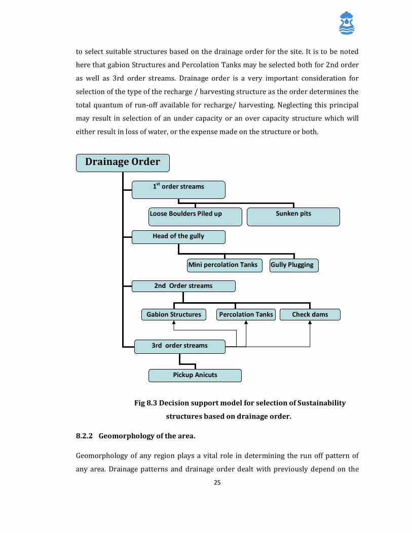
to select suitable structures based on the drainage order for the site. It is to be noted
here that gabion Structures and Percolation Tanks may be selected both for 2nd order
as well as 3rd order streams. Drainage order is a very important consideration for
selection of the type of the recharge / harvesting structure as the order determines the
total quantum of run-off available for recharge/ harvesting. Neglecting this principal
may result in selection of an under capacity or an over capacity structure which will
either result in loss of water, or the expense made on the structure or both.
Fig 8.3 Decision support model for selection of Sustainability
structures based on drainage order.
8.2.2 Geomorphology of the area.
Geomorphology of any region plays a vital role in determining the run off pattern of
any area. Drainage patterns and drainage order dealt with previously depend on the
Drainage Order
1st order streams
2nd Order streams
3rd order streams
Gabion Structures Percolation Tanks
Pickup Anicuts
Loose Boulders Piled up Sunken pits
Head of the gully
Mini percolation Tanks Gully Plugging
Check dams
26
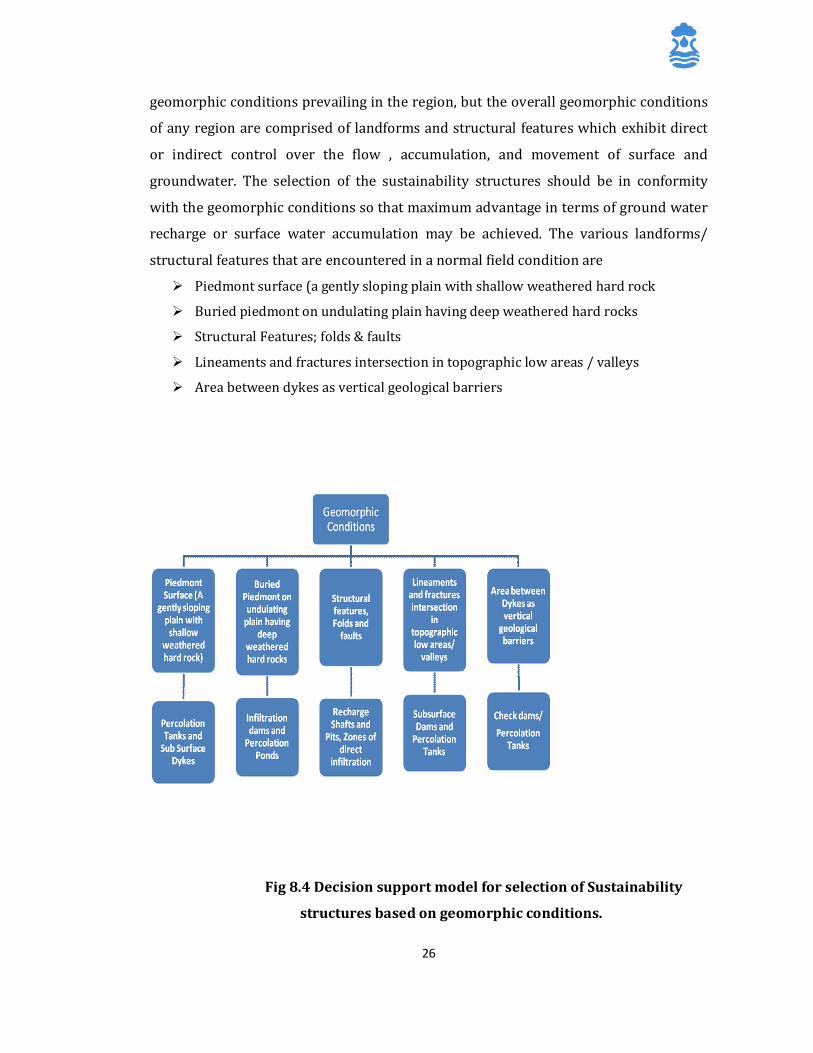
geomorphic conditions prevailing in the region, but the overall geomorphic conditions
of any region are comprised of landforms and structural features which exhibit direct
or indirect control over the flow , accumulation, and movement of surface and
groundwater. The selection of the sustainability structures should be in conformity
with the geomorphic conditions so that maximum advantage in terms of ground water
recharge or surface water accumulation may be achieved. The various landforms/
structural features that are encountered in a normal field condition are
Ø Piedmont surface (a gently sloping plain with shallow weathered hard rock
Ø Buried piedmont on undulating plain having deep weathered hard rocks
Ø Structural Features; folds & faults
Ø Lineaments and fractures intersection in topographic low areas / valleys
Ø Area between dykes as vertical geological barriers
Fig 8.4 Decision support model for selection of Sustainability
structures based on geomorphic conditions.
27
8.2.3 Hydrogeology of the area
Detailed knowledge of geological and hydrological features of the area is necessary
for adequately selecting the site and the type of recharge structure. In particular,
the features, parameters and data to be considered are: geological boundaries;
hydraulic boundaries; inflow and outflow of waters; storage capacity; porosity;
hydraulic conductivity; transmissivity; natural discharge of springs; water
resources available for recharge; natural recharge; water balance; lithology; depth
of the aquifer; and tectonic boundaries. The aquifers best suited for artificial
recharge are those aquifers which absorb large quantities of water and do not
release them too quickly. Theoretically this will imply that the vertical hydraulic
conductivity is high, while the horizontal hydraulic conductivity is moderate. These
two conditions are not often encountered in nature.
Ø Synthesize all the available data on hydrogeology from different agencies
such as HGM maps, water table contour maps, pre monsoon and post
monsoon water table fluctuation maps.
Ø Geophysical studies: the application of geophysical methods is to bring out a
comparative picture of the sub-surface litho environment, surface
manifestation of such structures, and correlate them with the
hydrogeological setting. it can identify the brackish/fresh ground water
interface, contaminated zone (saline) and the area prone to seawater
intrusion.
A table detailing the selection of sustainability structures based on Geology of the area
is given below:

28
Suitability of Artificial Recharge Structures for Different Hydrogeological Settings Group I - Consolidated Formations:
This group covers the hard crystalline igneous and metamorphic rocks and Pre-Cambrian sedimentary formations. The late Mesozoic, early Tertiary and Deccan and Rajamahal Volcanics, which cover a large area of the country, are also included in this group
Geologic
Age Rock
Formation Rock Types Hydrogeologic Characteristics Artificial Recharge Structures
Suitable Remarks
Archaean (4000 to 1500 million years)
Pre- Cambrians (1500 to 600 million years)
Jurassic Upper cretaceous to Eocene (110 to 60 million years)
Archaean Complex
Dharwars Aravallis to equivalent formations.
Cuddapahs, Delhi & equivalent systems.
Rajmahal traps Deccan traps
(a)Granites Gneisses, Charnokites, Khodalites (b)Schists, Slates,Phyllites (c)Banded Hematite Quartzites (Iron ore series)
(a)Consolidated sandstones, shales, Conglomerates (b)Limestones, Dolomites (c)Quartzites, Marbles (d)Intrusive granites & volcanic
(a)Basalts, Dolerites (b) Diorites
Poor primary porosity. limited fracture porosity. Weathering aided by secondary openings adds to the porosity & permeability. Limestones at places give rise to large ground water storage/circulation.
Ground water circulation is generally limited to 100m depth , occasionally fractures at deeper levels occur .
1. Percolation tanks 2. Nalah Bunds 3. Gully plugs 4. Contour Bund 5. Bench Terracing. 6. Recharge pits and shafts. 7.Gravity recharge wells 8. Induced recharge wells in favourable situations. 9. Ground water Dam (Under ground Bandhara) and Fracture sealing cementation. 10. Borehole Blasting & Hydro fracturing. 11. Various combination of above methods as per the site situations.
1. Limited artificial recharge may be accepted through a single structure, which benefits a limited area. More structures, spread over the watershed are required to create significant impact.
2. Injection recharge wells are not considered suitable due to limited intake possible in the deeper aquifers

29
Group-II: Semi Consolidated formations:
The sedimentary formations ranging in age between the Upper Carboniferous to Tertiary, which though lithified are relatively less consolidated and soft as compared to the consolidated formation have been included in this group. The hydrogeologic characteristics of the group are intermediate between the consolidated and the unconsolidated groups
Geologic Age
Rock Formation Rocks Types Hydrogeologic characteristics Structures suitable for Artificial Recharge
Remarks Upper Carboni- ferous to Jurassic (275 to 150 Million years)
Eocene to Lower Pleisto- cene (60 to 1 Mill ion years)
Gondwana Group
Jurassics of Kutch and Rajasthan, Bagh beds, Lametas & Cretaceous of Trichinapalli & Chharat
Hill Limestone, Murees of Jammu, Rajmundri Sandstone, Subathus, Dagshai and Kasaulis of Shimla hills, Jaintia, Barail, Surma, Tipam, Dupitila and Dihing of Assam , upper, middle & lower Siwaliks of Himalayan Foot Hill Zone, Tertiary Strata of Rajasthan, Kutch, Gujarat, Pondicherry, A.P, Ratnagiri (Maharashtra), Baripada (Orissa), Quilon, Varkalli (Kerala), Cuddalore (Tamil Nadu)
(a)Boulder pebble bed (b) Sandstones ( c)Shales (d) Coal seams
(a) Sandstones (b) Calcareous Sst. (c) Shales (d) Quartzites (e) Limestones
(a Sandstones (b) Shales (c) Conglomerates and Pebble beds & boulder conglomerate (d) Sands (e) Clays
The pebble & gravel beds, sandstones and boulder conglomerates possess moderate primary porosity. The shales have poor potential. The Gondwana group sand stones possess good potential. This group occurs in parts of West Bengal, Bihar, Orissa, Maharashtra and Andhra Pradesh.
Tertiary sandstones of Rajasthan, Gujarat, Kutch, Kerala, Tamil Nadu, Andhra Pradesh and Orissa have relatively better potential.
The semi-consolidated group is exposed extending through J & K, H.P, Punjab, Haryana, U.P., Sikkim, West Bengal, Assam and the North Eastern States. More potential when these occur in the valley areas. The Murees, Dagshai, Kasauli, Subathus and lower Siwaliks are relatively hard & compact and have poor potential. Siwalik sand stones lying at higher elevations do not form aquifers. The upper Siwaliks and Tertiary sandstones in NE sTATES display moderate ground water potential in suitable topographic locations.
1. Percolation Tanks 2. Nalah Bunds 3. Gully plug 4. Bench terracing 5. Contour Bund 6. Groundwater dams 7. Stream Modification 8. Recharge Basin, Pits and shafts 9. Gravity recharge wells 10. Induced Recharge
Confined Aquifer
1. Injection wells in favourable situation.
1. Sand- stones form the main rock type having potential for artificial recharge structures.
30
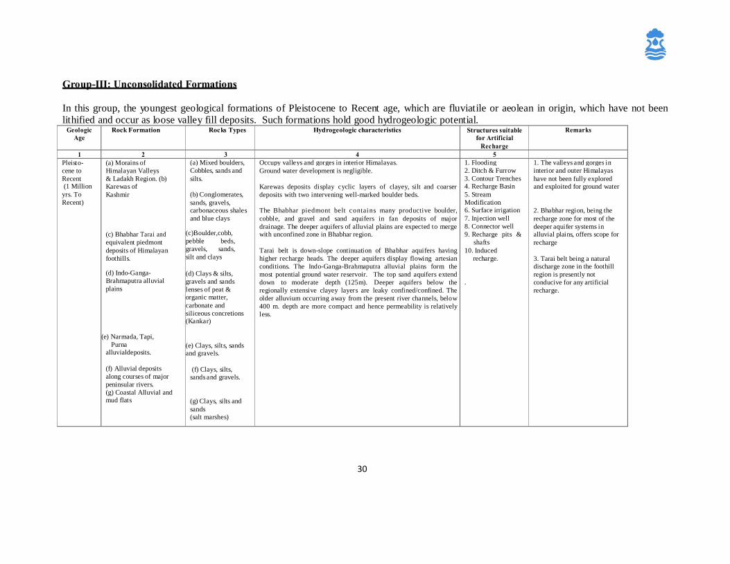
Group-III: Unconsolidated Formations
In this group, the youngest geological formations of Pleistocene to Recent age, which are fluviatile or aeolean in origin, which have not been lithified and occur as loose valley fill deposits. Such formations hold good hydrogeologic potential.
Geologic Age
Rock Formation Rocks Types Hydrogeologic characteristics Structures suitable for Artificial
Recharge Remarks
1 2 3 4 5 Pleisto- cene to Recent (1 Million
yrs. To Recent)
(a) Morains of Himalayan Valleys & Ladakh Region. (b) Karewas of Kashmir
(c) Bhabhar Tarai and equivalent piedmont deposits of Himalayan foothills.
(d) Indo-Ganga- Brahmaputra alluvial plains
(e) Narmada, Tapi, Purna alluvialdeposits. (f) Alluvial deposits along courses of major peninsular rivers. (g) Coastal Alluvial and mud flats
(a) Mixed boulders, Cobbles, sands and silts.
(b) Conglomerates, sands, gravels, carbonaceous shales and blue clays
(c)Boulder,cobb, pebble beds, gravels, sands, silt and clays (d) Clays & silts, gravels and sands lenses of peat & organic matter, carbonate and siliceous concretions (Kankar)
(e) Clays, silts, sands and gravels.
(f) Clays, silts, sands and gravels.
(g) Clays, silts and sands (salt marshes)
Occupy valleys and gorges in interior Himalayas. Ground water development is negligible. Karewas deposits display cyclic layers of clayey, silt and coarser deposits with two intervening well-marked boulder beds. The Bhabhar piedmont belt contains many productive boulder, cobble, and gravel and sand aquifers in fan deposits of major drainage. The deeper aquifers of alluvial plains are expected to merge with unconfined zone in Bhabhar region.
Tarai belt is down-slope continuation of Bhabhar aquifers having higher recharge heads. The deeper aquifers display flowing artesian conditions. The Indo-Ganga-Brahmaputra alluvial plains form the most potential ground water reservoir. The top sand aquifers extend down to moderate depth (125m). Deeper aquifers below the regionally extensive clayey layers are leaky confined/confined. The older alluvium occurring away from the present river channels, below 400 m. depth are more compact and hence permeability is relatively less.
1. Flooding 2. Ditch & Furrow 3. Contour Trenches 4. Recharge Basin 5. Stream Modification 6. Surface irrigation 7. Injection well 8. Connector well 9. Recharge pits & shafts 10. Induced recharge.
.
1. The valleys and gorges in interior and outer Himalayas have not been fully explored and exploited for ground water
2. Bhabhar region, being the recharge zone for most of the deeper aquifer systems in alluvial plains, offers scope for recharge
3. Tarai belt being a natural discharge zone in the foothill region is presently not conducive for any artificial recharge.
31
Geologic Age
Rock Formation Rocks Types Hydrogeologic characteristics Structures suitable for
Artificial
Rem1 2 3 4 5
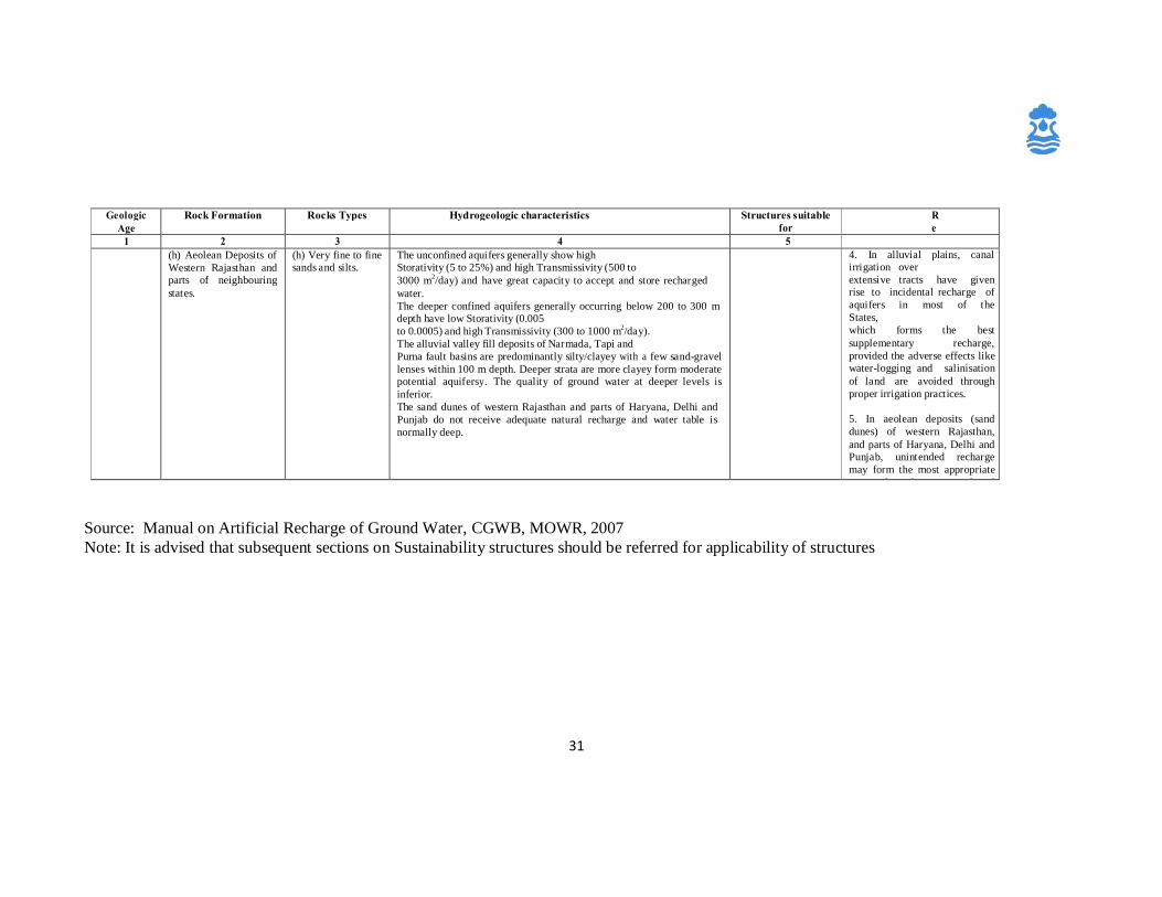
(h) Aeolean Deposits of Western Rajasthan and parts of neighbouring states.
(h) Very fine to fine sands and silts.
The unconfined aquifers generally show high Storativity (5 to 25%) and high Transmissivity (500 to 3000 m2/day) and have great capacity to accept and store recharged water. The deeper confined aquifers generally occurring below 200 to 300 m depth have low Storativity (0.005 to 0.0005) and high Transmissivity (300 to 1000 m2/day). The alluvial valley fill deposits of Narmada, Tapi and Purna fault basins are predominantly silty/clayey with a few sand-gravel lenses within 100 m depth. Deeper strata are more clayey form moderate potential aquifersy. The quality of ground water at deeper levels is inferior. The sand dunes of western Rajasthan and parts of Haryana, Delhi and Punjab do not receive adequate natural recharge and water table is normally deep.
4. In alluvial plains, canal irrigation over extensive tracts have given rise to incidental recharge of aquifers in most of the States, which forms the best supplementary recharge, provided the adverse effects like water-logging and salinisation of land are avoided through proper irrigation practices.
5. In aeolean deposits (sand dunes) of western Rajasthan, and parts of Haryana, Delhi and Punjab, unintended recharge may form the most appropriate option if canal water transferred
Source: Manual on Artificial Recharge of Ground Water, CGWB, MOWR, 2007 Note: It is advised that subsequent sections on Sustainability structures should be referred for applicability of structures
32
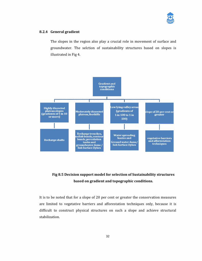
8.2.4 General gradient
The slopes in the region also play a crucial role in movement of surface and
groundwater. The selction of sustainability structures based on slopes is
illustrated in Fig 4.
Fig 8.5 Decision support model for selection of Sustainability structures
based on gradient and topographic conditions.
It is to be noted that for a slope of 20 per cent or greater the conservation measures
are limited to vegetative barriers and afforestation techniques only, because it is
difficult to construct physical structures on such a slope and achieve structural
stabilization.

33
8.2.5 Type of source
The sustainability structure may be sometimes targeted towards particular source. In
such cases, the structures are selected on the basis of the type of source, its size
parameters, and hydrogeological yield characteristics of the particular source. Direct
recharge to aquifer is feasible with the help of the groundwater exploitation source
itself, since these sources reach up to the aquifer and they act as recharge structures
when connected to run off.
Majority of the groundwater based sources can be grouped into
1. Borewell
2. Openwell
3. Springs
While the surface water sources can be
1. Lakes
2. Rivers
3. Reservoirs
Moreover other than sustainability structures there are certain processes by which
the sustainability of an existing source may be enhanced by increasing its yield. These
processes are listed below
1. Borewell Blasting technique
2. Roof top Rainwater Harvesting
3. Dugwell Recharge
4. Desilting
5. Repairs and restructuring of dams.
A decision support model for these structures/processes to be selected on the basis of
the type of source for groundwater sources is shown in Fig 5. A model for selection of
surface water sources sustainability structure is given in Fig 6.
34
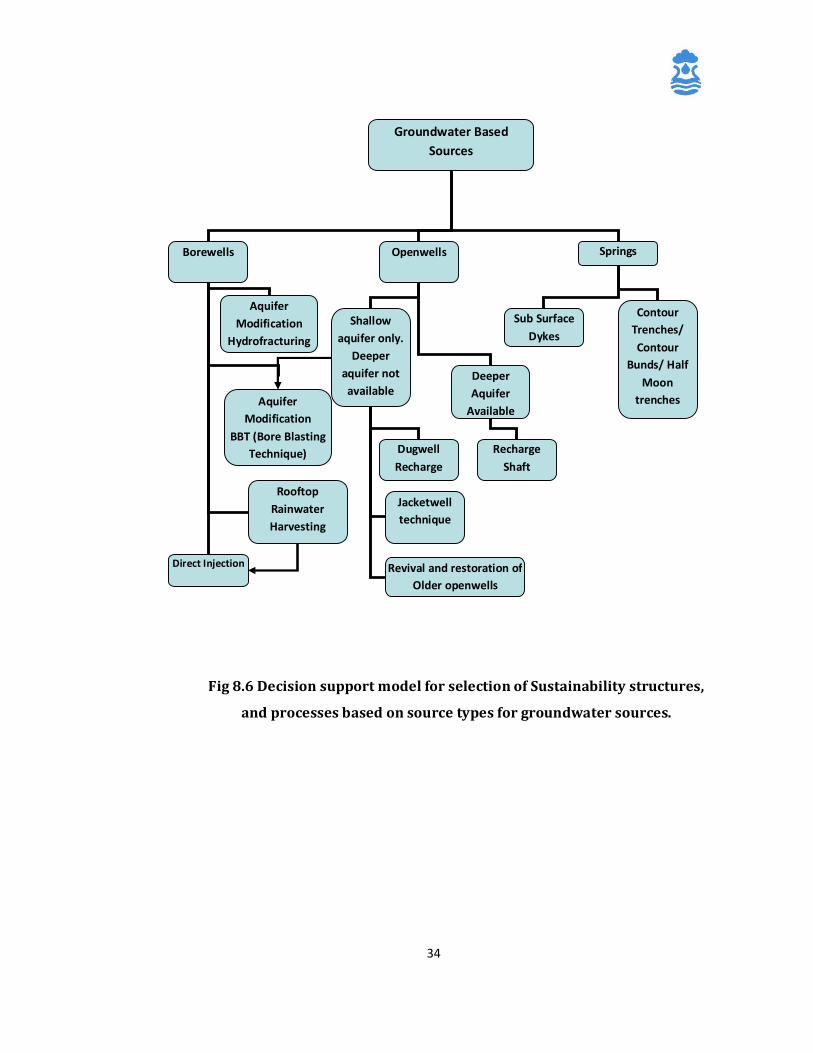
Fig 8.6 Decision support model for selection of Sustainability structures,
and processes based on source types for groundwater sources.
Groundwater Based Sources
Borewells Openwells Springs
Direct Injection
Shallow aquifer only.
Deeper aquifer not available
Sub Surface Dykes
Contour Trenches/ Contour
Bunds/ Half Moon
trenches Aquifer Modification
BBT (Bore Blasting Technique)
Deeper Aquifer
Available
Dugwell Recharge
Recharge Shaft
Rooftop Rainwater Harvesting
Aquifer Modification
Hydrofracturing
Jacketwell technique
Revival and restoration of Older openwells
35
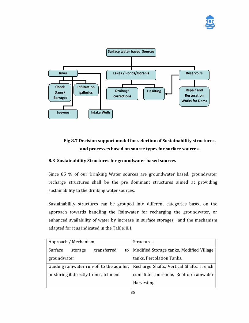
Fig 8.7 Decision support model for selection of Sustainability structures,
and processes based on source types for surface sources.
8.3 Sustainability Structures for groundwater based sources
Since 85 % of our Drinking Water sources are groundwater based, groundwater
recharge structures shall be the pre dominant structures aimed at providing
sustainability to the drinking water sources.
Sustainability structures can be grouped into different categories based on the
approach towards handling the Rainwater for recharging the groundwater, or
enhanced availability of water by increase in surface storages, and the mechanism
adapted for it as indicated in the Table. 8.1
Approach / Mechanism Structures
Surface storage transferred to
groundwater
Modified Storage tanks, Modified Village
tanks, Percolation Tanks.
Guiding rainwater run-off to the aquifer,
or storing it directly from catchment
Recharge Shafts, Vertical Shafts, Trench
cum filter borehole, Rooftop rainwater
Harvesting
Surface water based Sources
River Lakes / Ponds/Ooranis Reservoirs
Check Dams/
Barrages
Drainage corrections
Infiltration galleries Repair and
Restoration Works for Dams
Desilting
Leevees Intake Wells
36
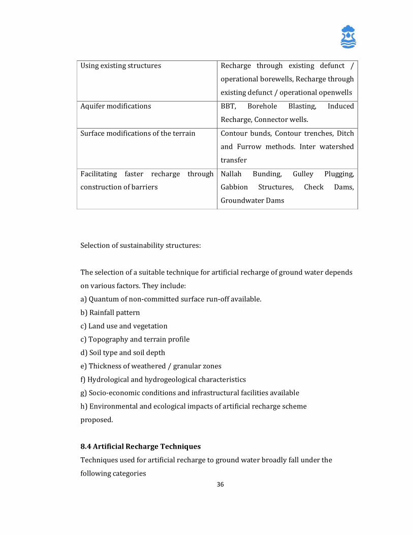
Using existing structures Recharge through existing defunct /
operational borewells, Recharge through
existing defunct / operational openwells
Aquifer modifications BBT, Borehole Blasting, Induced
Recharge, Connector wells.
Surface modifications of the terrain Contour bunds, Contour trenches, Ditch
and Furrow methods. Inter watershed
transfer
Facilitating faster recharge through
construction of barriers
Nallah Bunding, Gulley Plugging,
Gabbion Structures, Check Dams,
Groundwater Dams
Selection of sustainability structures:
The selection of a suitable technique for artificial recharge of ground water depends
on various factors. They include:
a) Quantum of non-committed surface run-off available.
b) Rainfall pattern
c) Land use and vegetation
c) Topography and terrain profile
d) Soil type and soil depth
e) Thickness of weathered / granular zones
f) Hydrological and hydrogeological characteristics
g) Socio-economic conditions and infrastructural facilities available
h) Environmental and ecological impacts of artificial recharge scheme
proposed.
8.4 Artificial Recharge Techniques
Techniques used for artificial recharge to ground water broadly fall under the
following categories

37
I) Direct Methods
A) Surface Spreading Techniques
a) Flooding
b) Ditch and Furrows
c) Recharge Basins
d) Runoff Conservation Structures
i) Bench Terracing
ii) Contour Bunds and Contour Trenches
iii) Gully Plugs, Nalah Bunds, Check Dams
iv) Percolation Ponds
e) Stream Modification / Augmentation
B) Sub-surface Techniques
a) Injection Wells (Recharge Wells)
b) Gravity Head Recharge Wells
c) Recharge Pits and Shafts
II) Indirect Methods
A) Induced Recharge from Surface Water Sources;
B) Aquifer Modification
i) Bore Blasting.
ii) Hydro-fracturing.
III) Combination Methods
In addition to the above, ground water conservation structures like Subsurface dykes
(Bandharas) and Fracture Sealing Cementation techniques are also used to arrest
subsurface flows.
Aquifer disposition plays a decisive role in choosing the appropriate technique of
artificial recharge of ground water ( Todd and Mays, 2005)
Fig 8.8 Aquifer Disposition
38
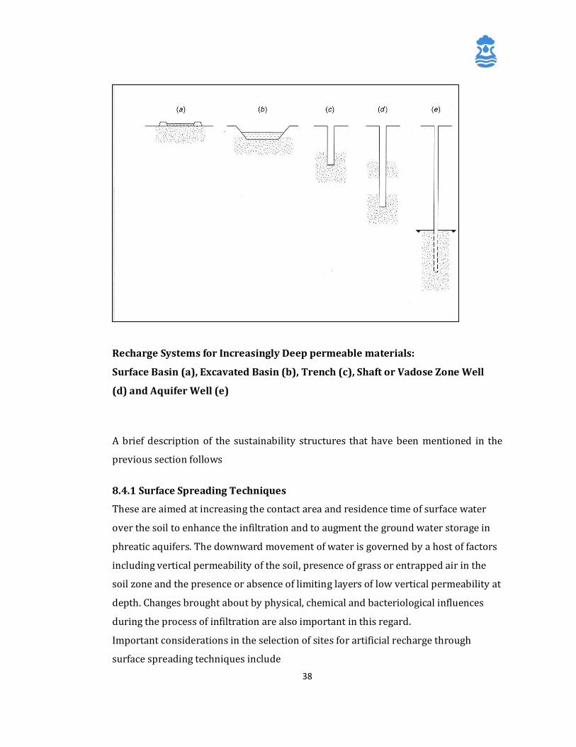
Recharge Systems for Increasingly Deep permeable materials:
Surface Basin (a), Excavated Basin (b), Trench (c), Shaft or Vadose Zone Well
(d) and Aquifer Well (e)
A brief description of the sustainability structures that have been mentioned in the
previous section follows
8.4.1 Surface Spreading Techniques
These are aimed at increasing the contact area and residence time of surface water
over the soil to enhance the infiltration and to augment the ground water storage in
phreatic aquifers. The downward movement of water is governed by a host of factors
including vertical permeability of the soil, presence of grass or entrapped air in the
soil zone and the presence or absence of limiting layers of low vertical permeability at
depth. Changes brought about by physical, chemical and bacteriological influences
during the process of infiltration are also important in this regard.
Important considerations in the selection of sites for artificial recharge through
surface spreading techniques include
39
i. The area should have gently sloping land without gullies or ridges.
ii. The aquifer being recharged should be unconfined, permeable and sufficiently
thick to provide storage space.
iii. The surface soil should be permeable and have high infiltration rate.
iv. Vadose zone should be permeable and free from clay lenses.
v. Ground water levels in the phreatic zone should be deep enough to
accommodate the recharged water so that there is no water logging.
vi. The aquifer material should have moderate hydraulic conductivity so that the
recharged water is retained for sufficiently long periods in the aquifer and can
be used when needed.
The most common surface spreading techniques used for artificial recharge to ground
water are flooding, ditch and furrows and recharge basins.
8.4.1.1 Flooding :
This technique is ideal for lands adjoining rivers or irrigation canals in which water
levels remain deep even after monsoons and where sufficient non-committed surface
water supplies are available. To ensure proper contact time and water spread,
embankments are provided on two sides to guide the unutilized surface water to a
return canal to carry the excess water to the stream or canal.
Flooding method helps reduce the evaporation losses from the surface water system,
is the least expensive of all artificial recharge methods available and has very low
maintenance costs
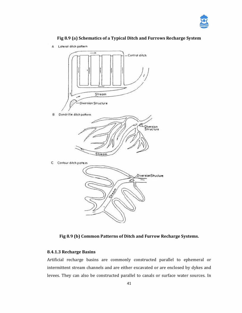
8.4.1.2 Ditch and Furrows method
This method involves construction of shallow, flat-bottomed and closely spaced
ditches or furrows to provide maximum water contact area for recharge from source
stream or canal. The ditches should have adequate slope to maintain flow velocity and
minimum deposition of sediments. The widths of the ditches are typically in the range
of 0.30 to 1.80 m. A collecting channel to convey the excess water back to the source
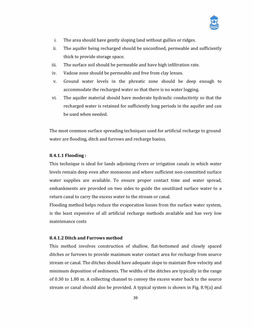
stream or canal should also be provided. A typical system is shown in Fig. 8.9(a) and
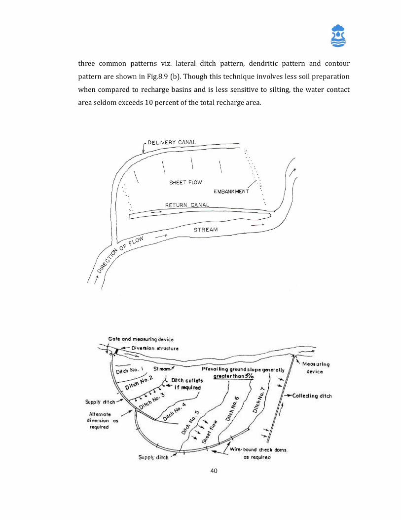
40
three common patterns viz. lateral ditch pattern, dendritic pattern and contour
pattern are shown in Fig.8.9 (b). Though this technique involves less soil preparation
when compared to recharge basins and is less sensitive to silting, the water contact
area seldom exceeds 10 percent of the total recharge area.
41
Fig 8.9 (a) Schematics of a Typical Ditch and Furrows Recharge System
Fig 8.9 (b) Common Patterns of Ditch and Furrow Recharge Systems.
8.4.1.3 Recharge Basins
Artificial recharge basins are commonly constructed parallel to ephemeral or
intermittent stream channels and are either excavated or are enclosed by dykes and
levees. They can also be constructed parallel to canals or surface water sources. In

42
alluvial areas, multiple recharge basins can be constructed parallel to the streams
(Fig.8.10), with a view to a) increase the water contact time, b) reduce suspended
material as water flows from one basin to another and c) to facilitate periodic
maintenance such as scraping of silt etc. to restore the infiltration rates by bypassing
the basin under restoration.
Fig 8.10 Schematics of a Typical Recharge Basin
In addition to the general design guidelines mentioned, other factors to be considered
while constructing recharge basins include
a) area selected for recharge should have gentle ground slope.
b) the entry and exit points for water should be diagonally opposite to
facilitate adequate water circulation in individual basins,
c) water released into the basins should be as sediment – free as possible and
d) rate of inflow into the basin should be slightly more than the infiltration capacity of
all the basins.
8.4.2 Runoff Conservation Structures
These are normally multi-purpose measures, mutually complementary and conducive
to soil and water conservation, afforestation and increased agricultural productivity.
They are suitable in areas receiving low to moderate rainfall mostly during a single
43
monsoon season and having little or no scope for transfer of water from other areas.
Different measures applicable to runoff zone, recharge zone and discharge zone are
available. The structures commonly used are bench terracing, contour bunds, gully
plugs, nalah bunds, check dams and percolation ponds.
8.4.2.1 Bench Terracing
Bench terracing involves leveling of sloping lands with surface gradients up to 8
percent and having adequate soil cover for bringing them under irrigation. It helps in
soil conservation and holding runoff water on the terraced area for longer durations,
leading to increased infiltration and ground water recharge.
For implementing terracing, a map of the watershed should be prepared by level
surveying and suitable benchmarks fixed. A contour map of 0.3 m contour interval is
then prepared. Depending on the land slope, the width of individual terrace should be
determined, which, in no case, should be less than 12 m. The upland slope between
two terraces should not be more than 1:10 and the terraces should be leveled. The
vertical elevation difference and width of terraces are controlled by the land slope.
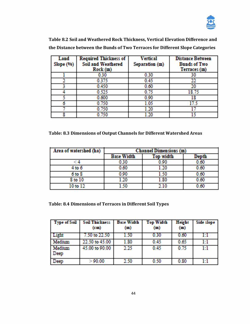
The soil and weathered rock thickness required, vertical elevation difference and the
distance between the bunds of two terraces for different slope categories are
furnished in Table.8.2
In case of a possibility of diverting surface runoff from local drainage for irrigation, as
required in case of paddy cultivation in high rainfall areas, outlet channels of
adequate dimensions are to be provided. The dimensions of the outlet
channels depend on the watershed area as shown below in Table 8.3. The terraces
should also be provided with bunds of adequate dimensions depending on the type of
soils as shown in Table. 8.4
44
Table 8.2 Soil and Weathered Rock Thickness, Vertical Elevation Difference and
the Distance between the Bunds of Two Terraces for Different Slope Categories
Table: 8.3 Dimensions of Output Channels for Different Watershed Areas
Table: 8.4 Dimensions of Terraces in Different Soil Types
45
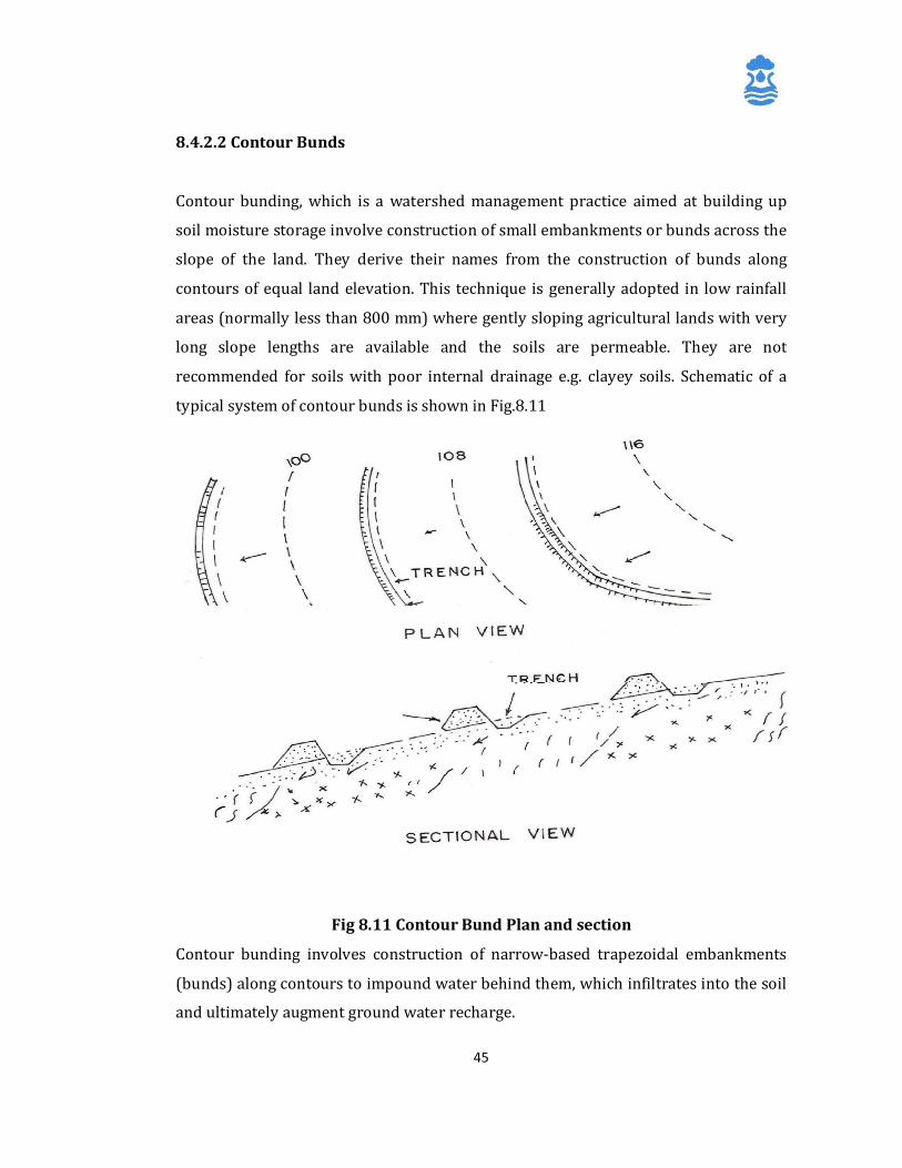
8.4.2.2 Contour Bunds
Contour bunding, which is a watershed management practice aimed at building up
soil moisture storage involve construction of small embankments or bunds across the
slope of the land. They derive their names from the construction of bunds along
contours of equal land elevation. This technique is generally adopted in low rainfall
areas (normally less than 800 mm) where gently sloping agricultural lands with very
long slope lengths are available and the soils are permeable. They are not
recommended for soils with poor internal drainage e.g. clayey soils. Schematic of a
typical system of contour bunds is shown in Fig.8.11
Fig 8.11 Contour Bund Plan and section
Contour bunding involves construction of narrow-based trapezoidal embankments
(bunds) along contours to impound water behind them, which infiltrates into the soil
and ultimately augment ground water recharge.
46
Field activities required prior to contour bunding include levelling of land by
removing local ridges and depressions, preparation of map of the area through
levelsurveying and fixing of bench marks. Elevation contours, preferably of 0.3 m
interval are then drawn, leaving out areas not requiring bunding such as habitations,
drainage etc. The alignment of bunds should then be marked on the map.
The important design aspects of contour bunds are
i) spacing,
ii) cross section and
iii) deviation freedom to go higher or lower than the contour bund elevation for
better
alignment on undulating land.
8.4.2.2.1 Spacing of Bunds: Spacing of contour bund is commonly expressed in
terms of vertical interval (V.I), which is defined as the difference in elevation between
two similar points on two consecutive bunds. The main criterion for spacing of bunds
is to intercept the water before it attains the erosive velocity. Spacing depends on
slope, soil, rainfall, cropping pattern and conservation practices.
Spacing of contour bunds is normally calculated using the formula
Vertical Interval (V.I) = 0.305 (XS+Y),
where
X is the rainfall factor,
S is the land slope (%) and
Y is the factor based on soil infiltration and crop cover during the erosive period of
rains
The rainfall factor ‘X’ is taken as 0.80 for scanty rainfall regions with annual rainfall
below 625 mm, as 0.60 for moderate rainfall regions with annual rainfall in the range
of 625 to 875 mm and as 0.40 for areas receiving annual rainfall in excess of 875 mm.
The factor ‘Y’ is taken as 1.0 for soils having poor infiltration with low crop cover
during erosive rains and as 2.0 for soils of medium to good infiltration and good crop
47
cover during erosive rains. When only one of these factors is favourable, the value of Y
is taken as 1.50. Vertical spacing can be increased by 10 percent or 15 cm to provide
better location, alignment or to avoid obstacles.
The horizontal interval between two bunds is calculated using the formula
Horizontal Interval (H.I) = V.I x 100/Slope
8.4.2.2.2 Cross Section of Contour Bunds: A trapezoidal cross section is usually
adopted for the bund. The design of the cross section involves determination of
height, top width, side slopes and bottom width of the bund. The height of the bund
depends on the slope of the land, spacing of the bunds and the rainfall excess expected
in 24-hour period for 10-year frequency in the area. Once the height is determined,
other dimensions can be worked out depending on the nature of the soil.
Height of the bund can be determined by the following methods
a) Arbitrary Design: The depth of impounding is designed as 30 cm. 30 cm is
provided as depth flow over the crust of the outlet weir and 20 cm is
provided as free board. The overall height of the bund in this case will be
80 cm. With top width of 0.50 m and base width of 2 m, the side slope will
be 1:1 and the cross section, 1 sq m.
b) The height of bund to impound runoff from 24 hour rain storm for a given
frequency can be calculated by the formula
H=
√ Re x V.I 50
where
H is the depth of impounding behind the bund (m),
Re is the 24 hour rainfall excess (cm) and
VI is the vertical interval (m)
To the height so computed, 20 percent extra height or a minimum of 15cm is added
for free board and another 15 to 20 percent extra height is added to compensate for
48
the settlement due to consolidation.
Top width of the bund is normally kept as 0.3 to 0.6 m to facilitate planting of
grasses. Side slopes of the bund are dependent on the angle of repose of the soil in
the area and commonly range from 1:1 for clayey soils to 2:1 for sandy soils. Base
width of the bund depends on the hydraulic gradient of the water in the bund
material due to the impounding water. A general value of hydraulic gradient
adopted is 4:1. The base should be sufficiently wide so that the seepage line should
not appear above the toe on the downstream side of the bund.
Size of the bund is expressed in terms of its cross-sectional area. The cross sectional
area of bunds depends on the soil type and rainfall and may vary from 0.50 to 1.0 sq
m in different regions.
The length of bunds per hectare of land is denoted by the Bunding Intensity, which
can be computed as
Bunding Intensity = 100 S
V.I
where
S is the land slope (%) and
V.I is the vertical interval (m)
The earthwork for contour bunding includes the main contour bund and side and
lateral bunds. The area of cross-section of side and lateral bunds is taken equal to
themain contour bund. The product of cross sectional area of the bund and the
bunding intensity gives the quantity of earthwork required for bunding / hectare of
land.
8.4.2.2.3 Deviation Freedom: Strict adherence to contours while constructing bunds
is a necessary prerequisite for ensuring maximum conservation of moisture and soil.
However, to avoid excessive curvature of bunds, which makes agricultural operations
difficult, the following deviations are permitted
a) a maximum of 15 cm while cutting across a narrow ridge,
b) a maximum of 30 cm while crossing a gully or depression and
49
c) a maximum of 1.5 m while crossing a sharp, narrow depression not exceeding 5 m
in width.
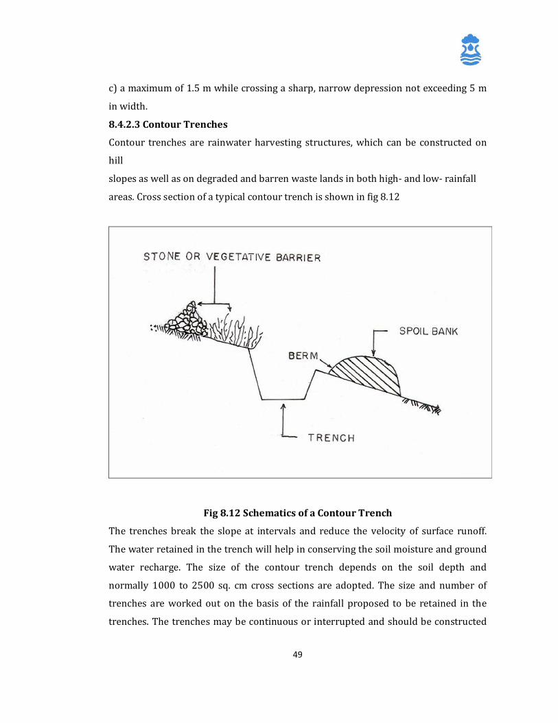
8.4.2.3 Contour Trenches
Contour trenches are rainwater harvesting structures, which can be constructed on
hill
slopes as well as on degraded and barren waste lands in both high- and low- rainfall
areas. Cross section of a typical contour trench is shown in fig 8.12
Fig 8.12 Schematics of a Contour Trench
The trenches break the slope at intervals and reduce the velocity of surface runoff.
The water retained in the trench will help in conserving the soil moisture and ground
water recharge. The size of the contour trench depends on the soil depth and
normally 1000 to 2500 sq. cm cross sections are adopted. The size and number of
trenches are worked out on the basis of the rainfall proposed to be retained in the
trenches. The trenches may be continuous or interrupted and should be constructed

50
along the contours. Continuous trenches are used for moisture conservation in low
rainfall area whereas intermittent trenches are preferred in high rainfall area.
The horizontal and vertical intervals between the trenches depend on rainfall, slope
and soil depth. In steeply sloping areas, the horizontal distance between the two
trenches will be less compared to gently sloping areas. In areas where soil cover is
thin, depth of trenching is restricted and more trenches at closer intervals need to be
constructed. In general, the horizontal interval may vary from 10 m in steep slopes to
about 25 m in gentle slopes.
8.4.2.4 Gully Plugs, Nalah Bunds and Check Dams
These structures are constructed across gullies, nalahs or streams to check the flow of
surface water in the stream channel and to retain water for longer durations in the
pervious soil or rock surface. As compared to gully plugs, which are normally
constructed across 1st order streams, nalah bunds and check dams are constructed
across bigger streams and in areas having gentler slopes. These may be temporary
structures such as brush wood dams, loose / dry stone masonry check dams, Gabion
check dams and woven wire dams constructed with locally available material or
permanent structures constructed using stones, brick and cement. Competent civil
and agro-engineering techniques are to be used in the design, layout and construction
of permanent check dams to ensure proper storage and adequate outflow of surplus
water to avoid scours on the downstream side for long-term stability of the dam.
The site selected for check dam should have sufficient thickness of permeable soils or
weathered material to facilitate recharge of stored water within a short span of time.
The water stored in these structures is mostly confined to the stream course and the
height is normally less than 2 m. These are designed based on stream width and
excess water is allowed to flow over the wall. In order to avoid scouring from excess
runoff, water cushions are provided on the downstream side. To harness maximum
runoff in the stream, a series of such check dams can be constructed to have recharge
on a regional scale. The design particulars of a cement nalah bund are shown in Fig.
8.13.

51
The following parameters should be kept in mind while selecting sites for check dams
/ nalah bunds:
i) The total catchment area of the stream should normally be between 40 and 100 ha.
Local situations can, however, be a guiding factor in this regard.
ii) The rainfall in the catchment should be preferably less than 1000 mm / annum.
iii) The stream bed should be 5 to 15 m wide and at least 1m deep.
iv) The soil downstream of the bund should not be prone to water
logging and should have a pH value between 6.5 and 8.
v) The area downstream of the Check Dam / bund should have irrigable land under
well irrigation.
vi) The Check dams / Nalah bunds should preferably be located in areas where
contour or graded bunding of lands have been carried out.
vii) The rock strata exposed in the ponded area should be adequately permeable to
cause ground water recharge.
Check dams / Nalah bunds are normally 10 to 15 m long, 1 to 3 m wide and 2 to 3 m
high, generally constructed in a trapezoidal form. Detailed studies are to be made in
the watershed prior to construction of the check dam to assess the current erosion
condition, land use and water balance. The community in the watershed should also
be involved in the planning and selection of the type and location of the structure.
For construction of the check dam, a trench, about 0.6 m wide in hard rock and l.2 m
wide in soft impervious rock is dug for the foundation of core wall. A core brick
cement wall, 0.6 m wide and raised at least 2.5m above the nalah bed is erected and
the remaining portion of trench back filled on upstream side by impervious clay. The
core wall is buttressed on both sides by a bund made up of local clays and stone
pitching is done on the upstream face. If the bedrock is highly fractured, cement
grouting is done to make the foundation leakage free.
8.4.2.5 Percolation Tanks
Percolation tanks, which are based on principles similar to those of nalah bunds, are
among the most common runoff harvesting structures in India. A percolation tank can
be defined as an artificially created surface water body submerging a highly
52
permeable land area so that the surface runoff is made to percolate and recharge the
ground water storage. They differ from nalah bunds in having larger reservoir areas.
They are not provided with sluices or outlets for discharging water from the tank for
irrigation or other purposes. They may, however, be provided with arrangements for
spilling away the surplus water that may enter the tank so as to avoid over-topping of
the tank bund.
It is possible to have more than one percolation tank in a catchment if sufficient
surplus runoff is available and the site characteristics favour artificial recharge
through such structures. In such situations, each tank of the group takes a share in the
yield of the whole catchment above it, which can be classified as
(i) 'free catchment', which is the catchment area that only drains into the tank
under consideration and
(ii) 'combined catchment', which is the area of the whole catchment above the
tank.
The difference between the combined and free catchment gives the area of the
catchment intercepted by the tanks located upstream of any tank. The whole
catchment of the highest tank on each drainage shall be its free catchment. Moreover,
each tank will receive the whole runoff from its free catchment, but from the
remainder of its catchment it will receive only the balance runoff that remains after
the upper tanks have been filled.
8.4.2.5.1 Site Selection Criteria:
The important site selection criteria for percolation ponds include
i. The hydrogeology of the area should be such that the litho-units occurring in
the area of submergence of the tank should have high permeability. The soils in
the catchment area of the tank should be sandy to avoid silting up of the tank
bed.
53
ii. The availability of non-committed surplus monsoon runoff should be sufficient
to ensure filling of the tank every year.
iii. As the yield of catchments in low rainfall areas generally varies between 0.44
to 0.55 M Cu m/sq km, the catchment area may be between 2.50 and 4.0 sq km
for small tanks and between 5.0 and 8.0 sq km for larger tanks.
iv. Selection of the size of a percolation tank should be governed by the
percolation capacity of the strata rather than the yield of the catchment. In
order to avoid wastage of water through evaporation, larger capacity tanks
should be constructed only if percolation capacity is proven to be good. If
percolation rates are low to moderate, tanks of smaller capacity may be
constructed. Percolation tanks are normally designed for storage capacities of
8 to 20 M cft. (2.26 to 5.66 M Cu m).
v. The depth of water impounded in the tank provides the recharge head and
hence it is necessary to design the tank to provide a minimum height of
ponded water column of 3 to 4.5 m and rarely 6 m above the bed level. This
would imply construction of tanks of large capacity in areas with steep
gradient.
vi. The purpose of construction of percolation tanks is to ensure recharge of
maximum possible surface water runoff to the aquifer in as short a period as
possible without much evaporation losses. Normally, a percolation tank should
not retain water beyond February.
vii. The percolation tank should be located downstream of runoff zone, preferably
toward the edge of piedmont zone or in the upper part of the transition zone.
Land slope between 3 and 5 percent is ideal for construction of percolation
tanks.
54
viii. There should be adequate area suitable for irrigation and sufficient number of
ground water abstraction structures within the command of the percolation
tank to fully utilise the additional recharge. The area benefited should have a
productive phreatic aquifer with lateral continuity up to the percolation tank.
The depth to water level in the area should remain more than 3 m below
ground level during post-monsoon period.
8.4.2.5.2 Investigations Required: An area, preferably the entire watershed,
needing additional ground water recharge is identified on the basis of declining water
level trends both during pre and post monsoon, increase in the demand of ground
water and water scarcity during lean period etc. Areas having scarcity of water during
summer in spite of incidences of flood during monsoons may also be considered for
artificial recharge.
A base map, preferably on 1:50,000 scale showing all available geological,
physiographical, hydrogeological and hydrological details along with land use,
cropping pattern etc. is a pre-requisite for the scientific planning. Survey of India
toposheets, aerial photographs and satellite imagery of the area may be consulted to
gather preliminary information about the area under study. The nature of catchment
as regards to the general slope, land use, forest cover, cropping pattern, soils, geology
etc. should be understood to assess their influence on runoff.
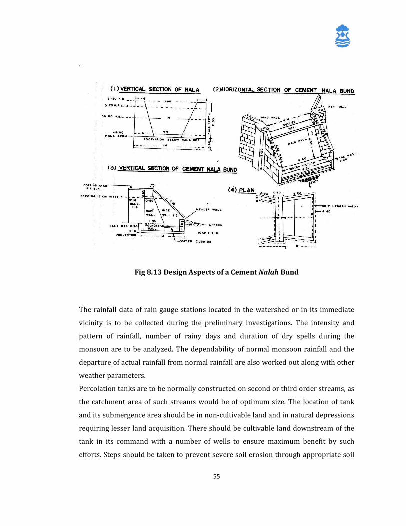
55
.
Fig 8.13 Design Aspects of a Cement Nalah Bund
The rainfall data of rain gauge stations located in the watershed or in its immediate
vicinity is to be collected during the preliminary investigations. The intensity and
pattern of rainfall, number of rainy days and duration of dry spells during the
monsoon are to be analyzed. The dependability of normal monsoon rainfall and the
departure of actual rainfall from normal rainfall are also worked out along with other
weather parameters.
Percolation tanks are to be normally constructed on second or third order streams, as
the catchment area of such streams would be of optimum size. The location of tank
and its submergence area should be in non-cultivable land and in natural depressions
requiring lesser land acquisition. There should be cultivable land downstream of the
tank in its command with a number of wells to ensure maximum benefit by such
efforts. Steps should be taken to prevent severe soil erosion through appropriate soil
56
conservation measures in the catchment. This will keep the tank free from siltation
which otherwise reduces the percolation efficiency and life of the structure.
Detailed geological and hydrogeological mapping is to be carried out in the area of
submergence, at the tank site and also downstream of the site to find out the
permeability of vadose zone and aquifer. The potential of additional storage and
capacity of aquifer to transmit the ground water in adjoining areas is also assessed
based on aquifer geometry. Infiltration rates of soils in the probable area of
submergence are to be determined through infiltration tests. Aquifer parameters of
water-bearing formations in the zone of influence may also be determined to assess
the recharge potential and number of feasible ground water structures in the area.
Periodic water level measurements along with ground water sampling for water
quality may be done before and after the construction of percolation tanks. Detailed
geological investigations may be carried out to study the nature and depth of
formation at the bund (dam) site for deciding the appropriate depth of cut off trench
(COT). This will help in reducing the visible seepage and also ensure safety and long
life of the structure. The depth of foundation and its treatment should be considered
on the basis of the nature of formation while designing and constructing the dam wall
and waste weir.
8.4.2.5.3 Engineering Aspects: A percolation tank is essentially an earthen structure
with a masonry spill way. It should be designed with maximum capacity utilisation,
long life span, cost-effectiveness and optimum recharge to ground water in mind.
Storage capacity, waste weir, drainage arrangements and cut off trench (COT) are the
important features of percolation tank that need proper design. The overall design of
the percolation tank is similar to that of an earthen dam constructed for minor
irrigation.
Detailed topographical survey to demarcate the area of submergence in natural
depression and alignment of dam line in the valley is to be taken up prior to
construction of the structure. A number of sections along and across the drainage are
prepared and the best suitable site is identified. The land availability and possibility of
land acquisition is explored during the survey. The spillway site is demarcated and is

57
designed in such a way that it allows the flow of surplus water based on single day
maximum rainfall after the tank is filled to its maximum capacity. The depth of
foundation for masonry work of waste weir etc. is decided depending on the nature of
formation. Cut Off Trench (COT) is provided to minimize the seepage losses across the
streambed. The depth of COT is generally 2-6 m below ground level depending upon
the subsurface strata. In order to avoid erosion of bund due to ripple action, stone
pitching is provided in the upstream direction up to High Flood Level (HFL).
The sources for availability of constructional material, especially clay and porous soil
for earthwork and stone rubble for pitching are to be identified.
a) Design of Storage Capacity: The storage capacity of a percolation tank may be
defined as the volume of water stored in the tank up to the Full Tank Level
(FTL). The storage capacity can be computed by using the contour plan of the
water-spread area of the tank. The total capacity of the tank will be the sum of
the capacities between successive contours. The smaller the contour interval,
the more accurate the capacity computation will be. The summation of all the
volumes between successive contours will be required for computing the
storage capacity of the tank. When contour plan is not available and only the
area of the tank at FTL is known, then the effective volume of the tank may be
roughly computed as the area multiplied by one third of the depth from FTL to
the deep bed of the tank. The tank is designed to ensure maximum utilisation
of its capacity. A structure of optimum capacity is the most cost effective. An
under-utilized structure leads to unproductive expenditure incurred on extra
earthwork. The design of storage capacity of a tank depends mainly upon the
proper estimation of catchment yield, which is calculated as,
Q = A * Strange's Coefficient
Where, Q is yield at site and A is area of the catchment.
Strange's coefficients for various amounts of monsoon rainfall for three categories of
catchments, i.e. good, average and bad are available from Strange's tables provided in

58
standard Hydrology text books. The rainfall data of 40-50 years, collected from the
nearest rain gauge station, may be used for design purposes. The percolation tanks
are to be designed for a realistic percentage of the yield of the catchment considering
the temporal distribution of monsoon rainfall. Another important consideration is the
fact that water stored in a percolation tank starts percolating immediately and the
terminal storage in the tank is not the cumulative storage from different spells of rain.
The concept of storage capacity of percolation ponds thus differs significantly from
that of an irrigation tank.
The catchment yield and basin configuration drawn from topographic surveys at site
determine the height of the percolation tank. The top of dam wall is normally kept 2-
3 m wide. Upstream and downstream slopes of the dam wall are normally taken as
2.5:1 and 2:1 respectively as recommended in design manual for minor irrigation
tanks. The design particular of a typical percolation tank is shown in Fig.6.8 along
with all relevant details.
b) Design of Tank Bund: The tank bund, for all practical purposes, is a small-sized
earthen dam and its design and construction should be carried out in accordance with
the principles applicable to earthen dams.
The bunds of a percolation pond may be of three types, i.e.
Type A: Homogeneous embankment type (Fig. 8.15(a))
Type B: Zoned Embankment Type (Fig. 8.15(b))
Type C: Diaphragm Type (Fig. 8.15(c))
Tank bunds in India are mostly of Type A and are constructed with soils excavated
from pits in the immediate vicinity of the bund and transported to the bund.
The most commonly adopted standards used for fixing the dimensions of tank bunds,
particularly in South India are given in Table 8.5 . In favourable soils such as gravels,
black loams etc., the side slopes of the bund may be kept at 0.5:1 for smaller tanks
with water depths not exceeding 2.50 m and 2:1 for larger tanks up to 5.0 m deep. In
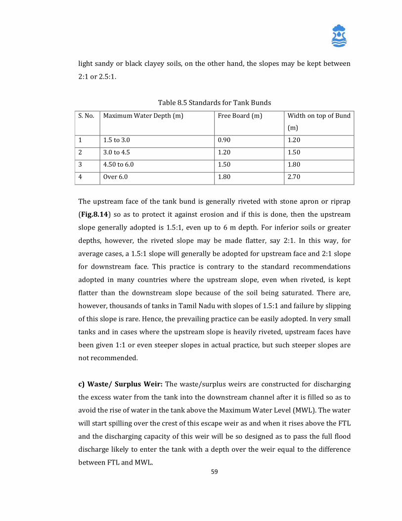
59
light sandy or black clayey soils, on the other hand, the slopes may be kept between
2:1 or 2.5:1.
Table 8.5 Standards for Tank Bunds
S. No. Maximum Water Depth (m) Free Board (m) Width on top of Bund
(m)
1 1.5 to 3.0 0.90 1.20
2 3.0 to 4.5 1.20 1.50
3 4.50 to 6.0 1.50 1.80
4 Over 6.0 1.80 2.70
The upstream face of the tank bund is generally riveted with stone apron or riprap
(Fig.8.14) so as to protect it against erosion and if this is done, then the upstream
slope generally adopted is 1.5:1, even up to 6 m depth. For inferior soils or greater
depths, however, the riveted slope may be made flatter, say 2:1. In this way, for
average cases, a 1.5:1 slope will generally be adopted for upstream face and 2:1 slope
for downstream face. This practice is contrary to the standard recommendations
adopted in many countries where the upstream slope, even when riveted, is kept
flatter than the downstream slope because of the soil being saturated. There are,
however, thousands of tanks in Tamil Nadu with slopes of 1.5:1 and failure by slipping
of this slope is rare. Hence, the prevailing practice can be easily adopted. In very small
tanks and in cases where the upstream slope is heavily riveted, upstream faces have
been given 1:1 or even steeper slopes in actual practice, but such steeper slopes are
not recommended.
c) Waste/ Surplus Weir: The waste/surplus weirs are constructed for discharging
the excess water from the tank into the downstream channel after it is filled so as to
avoid the rise of water in the tank above the Maximum Water Level (MWL). The water
will start spilling over the crest of this escape weir as and when it rises above the FTL
and the discharging capacity of this weir will be so designed as to pass the full flood
discharge likely to enter the tank with a depth over the weir equal to the difference
between FTL and MWL.
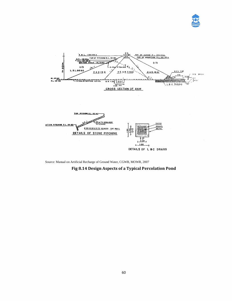
60
Source: Manual on Artificial Recharge of Ground Water, CGWB, MOWR, 2007
Fig 8.14 Design Aspects of a Typical Percolation Pond
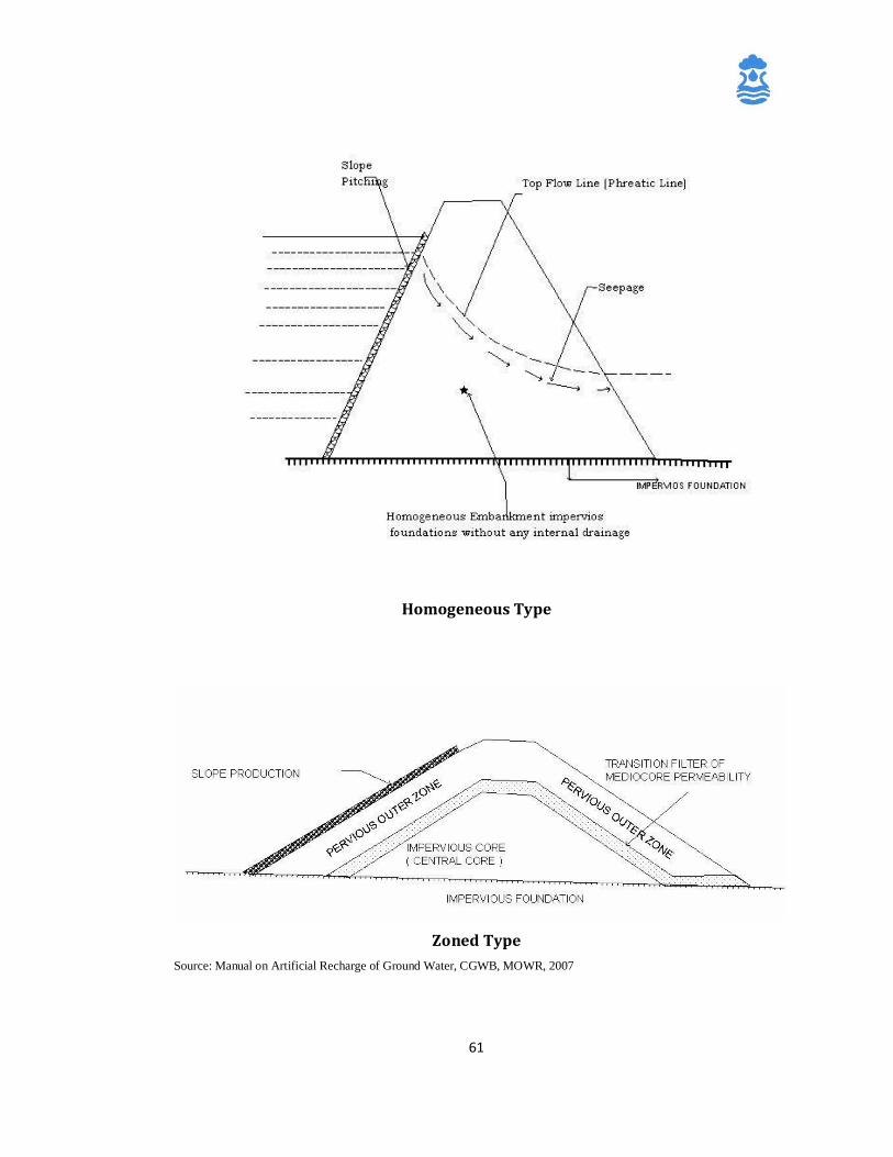
61
Homogeneous Type
Zoned Type
Source: Manual on Artificial Recharge of Ground Water, CGWB, MOWR, 2007
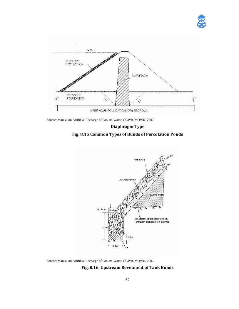
62
Source: Manual on Artificial Recharge of Ground Water, CGWB, MOWR, 2007
Diaphragm Type
Fig. 8.15 Common Types of Bunds of Percolation Ponds
Source: Manual on Artificial Recharge of Ground Water, CGWB, MOWR, 2007
Fig. 8.16. Upstream Revetment of Tank Bunds
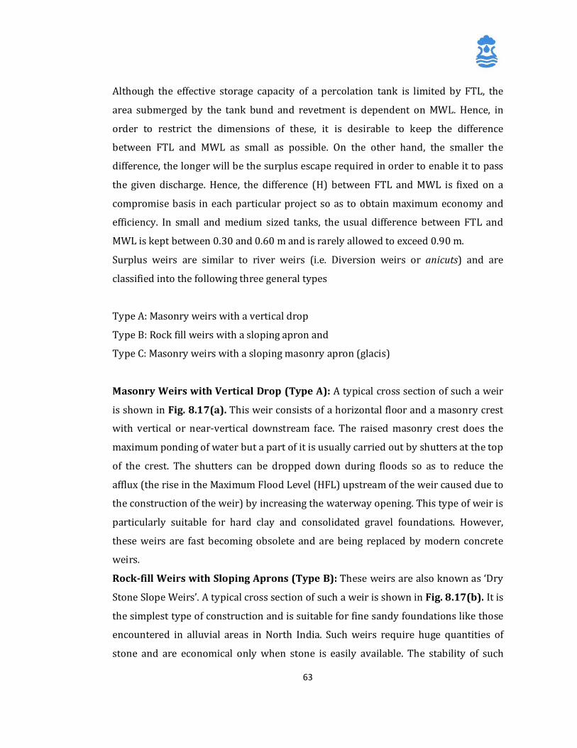
63
Although the effective storage capacity of a percolation tank is limited by FTL, the
area submerged by the tank bund and revetment is dependent on MWL. Hence, in
order to restrict the dimensions of these, it is desirable to keep the difference
between FTL and MWL as small as possible. On the other hand, the smaller the
difference, the longer will be the surplus escape required in order to enable it to pass
the given discharge. Hence, the difference (H) between FTL and MWL is fixed on a
compromise basis in each particular project so as to obtain maximum economy and
efficiency. In small and medium sized tanks, the usual difference between FTL and
MWL is kept between 0.30 and 0.60 m and is rarely allowed to exceed 0.90 m.
Surplus weirs are similar to river weirs (i.e. Diversion weirs or anicuts) and are
classified into the following three general types
Type A: Masonry weirs with a vertical drop
Type B: Rock fill weirs with a sloping apron and
Type C: Masonry weirs with a sloping masonry apron (glacis)
Masonry Weirs with Vertical Drop (Type A): A typical cross section of such a weir
is shown in Fig. 8.17(a). This weir consists of a horizontal floor and a masonry crest
with vertical or near-vertical downstream face. The raised masonry crest does the
maximum ponding of water but a part of it is usually carried out by shutters at the top
of the crest. The shutters can be dropped down during floods so as to reduce the
afflux (the rise in the Maximum Flood Level (HFL) upstream of the weir caused due to
the construction of the weir) by increasing the waterway opening. This type of weir is
particularly suitable for hard clay and consolidated gravel foundations. However,
these weirs are fast becoming obsolete and are being replaced by modern concrete
weirs.
Rock-fill Weirs with Sloping Aprons (Type B): These weirs are also known as ‘Dry
Stone Slope Weirs’. A typical cross section of such a weir is shown in Fig. 8.17(b). It is
the simplest type of construction and is suitable for fine sandy foundations like those
encountered in alluvial areas in North India. Such weirs require huge quantities of
stone and are economical only when stone is easily available. The stability of such
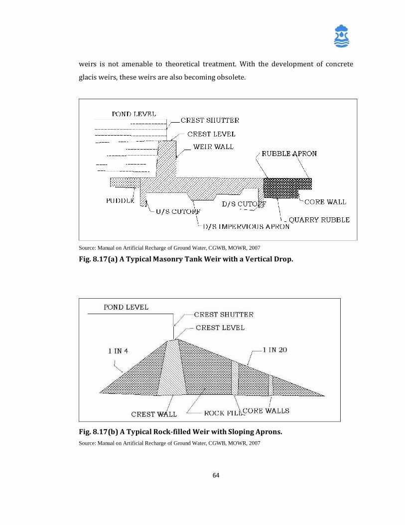
64
weirs is not amenable to theoretical treatment. With the development of concrete
glacis weirs, these weirs are also becoming obsolete.
Source: Manual on Artificial Recharge of Ground Water, CGWB, MOWR, 2007
Fig. 8.17(a) A Typical Masonry Tank Weir with a Vertical Drop.
Fig. 8.17(b) A Typical Rock-filled Weir with Sloping Aprons. Source: Manual on Artificial Recharge of Ground Water, CGWB, MOWR, 2007
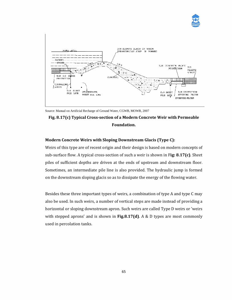
65
Source: Manual on Artificial Recharge of Ground Water, CGWB, MOWR, 2007
Fig. 8.17(c) Typical Cross-section of a Modern Concrete Weir with Permeable
Foundation.
Modern Concrete Weirs with Sloping Downstream Glacis (Type C):
Weirs of this type are of recent origin and their design is based on modern concepts of
sub-surface flow. A typical cross-section of such a weir is shown in Fig: 8.17(c). Sheet
piles of sufficient depths are driven at the ends of upstream and downstream floor.
Sometimes, an intermediate pile line is also provided. The hydraulic jump is formed
on the downstream sloping glacis so as to dissipate the energy of the flowing water.
Besides these three important types of weirs, a combination of type A and type C may
also be used. In such weirs, a number of vertical steps are made instead of providing a
horizontal or sloping downstream apron. Such weirs are called Type D weirs or 'weirs
with stepped aprons' and is shown in Fig.8.17(d). A & D types are most commonly
used in percolation tanks.
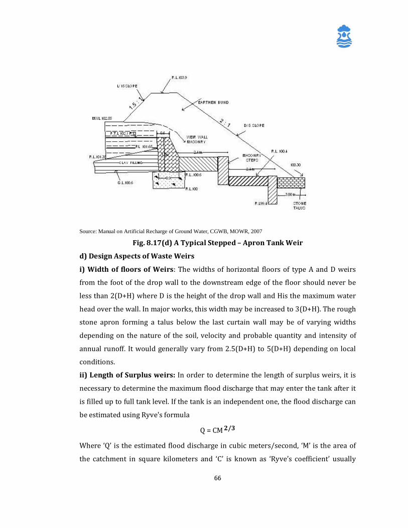
66
Source: Manual on Artificial Recharge of Ground Water, CGWB, MOWR, 2007
Fig. 8.17(d) A Typical Stepped – Apron Tank Weir d) Design Aspects of Waste Weirs
i) Width of floors of Weirs: The widths of horizontal floors of type A and D weirs
from the foot of the drop wall to the downstream edge of the floor should never be
less than 2(D+H) where D is the height of the drop wall and His the maximum water
head over the wall. In major works, this width may be increased to 3(D+H). The rough
stone apron forming a talus below the last curtain wall may be of varying widths
depending on the nature of the soil, velocity and probable quantity and intensity of
annual runoff. It would generally vary from 2.5(D+H) to 5(D+H) depending on local
conditions.
ii) Length of Surplus weirs: In order to determine the length of surplus weirs, it is
necessary to determine the maximum flood discharge that may enter the tank after it
is filled up to full tank level. If the tank is an independent one, the flood discharge can
be estimated using Ryve's formula
Q = CM 2/3
Where ‘Q’ is the estimated flood discharge in cubic meters/second, ‘M’ is the area of
the catchment in square kilometers and ‘C’ is known as ‘Ryve’s coefficient’ usually
67
ranging from 6.8 to 15 depending upon the topography of the catchment and intensity
of rainfall over the catchment. If the tank is part of a group of tanks, the flood
discharge likely to enter such a tank is calculated using the formula
Q = CM 2/3 - cm 2/3
Where ‘Q’ is the estimated flood discharge in cubic meters/second that is likely to
enter the tank in question, ‘M’ is the combined catchment area of all tanks above the
surplus of the tank in square kilometers, ‘m’ is the intercepted catchment area in
square kilometers by the upper tanks, ‘C’, Ryve's coefficient varying from 6.8 to 15
and ‘c’, modified coefficient which generally varies from 1/5 to 1/3 of C.
In case of catchments of less than two square kilometers, it is better to adopt
discharges obtained by calculating the runoff from the catchment with a precipitation
of 2.54 cm/hour (Equivalent to 1 Inch/Hour). The flood discharge obtained from a
catchment with 2.54 cm precipitation can be calculated from the following formula:
Q = 7M 2/3
Where ‘Q’ is the discharge in cubic meters/second obtained due to a precipitation of
2.54 cm/hr and ‘M’, the area of the catchment in square kilometers. After assessing the flood discharge and fixing the FTL and MWL with reference to the
storage requirements, the length of the surplus weir can be calculated from the
formula
Q = 2/3 Cd LH2 gH or 2.95 Cd LH3/2
where ‘Q’ is the quantum of flood water in cubic meter/second to be discharged, ‘L’,
the length of the weir in meter, ‘H’, the head over the weir or the difference between
MWL and FTL in meters and ‘Cd, the coefficient of discharge, which varies depending
upon the type of weir as given below in the table.
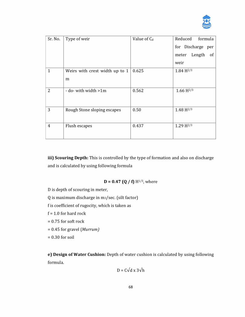
68
Sr. No. Type of weir Value of Cd Reduced formula
for Discharge per
meter Length of
weir
1 Weirs with crest width up to 1
m
0.625 1.84 H2/3
2 - do- with width >1m 0.562 1.66 H2/3
3 Rough Stone sloping escapes 0.50 1.48 H2/3
4 Flush escapes 0.437 1.29 H2/3
iii) Scouring Depth: This is controlled by the type of formation and also on discharge
and is calculated by using following formula
D = 0.47 (Q / f) H1/3, where
D is depth of scouring in meter,
Q is maximum discharge in m3/sec. (silt factor)
f is coefficient of rugocity, which is taken as
f = 1.0 for hard rock
= 0.75 for soft rock
= 0.45 for gravel (Murrum)
= 0.30 for soil e) Design of Water Cushion: Depth of water cushion is calculated by using following
formula.
D = C√d x 3√h
69
Where, D is depth of water column in m,
h is difference between level of water passing
over the weir and that of tail water (m)
d is vertical drop (m) and
c is a constant (coefficient of rugocity)
Length of water column (L) is calculated using following formula,
L = 6 √d
f) Design of Spill Channel: The Spill channel is designed on the basis of Maximum
flood discharge (Q), bed width (L), maximum flood lift (H) and bed slope. The area of
cross section (A) of waste weir is worked out as L * H (Sq m) and wetted perimeter
(P) is worked out as L + (H*D) in metres.
Hydraulic mean depth (R) is calculated as, R = A/P
Velocity (V) = (1/N) * R1/3 x √S (m/sec),
Where S is the slope and N is taken as 0.03
Capacity of discharge Q = A * V (m3 / sec)
The section capable of discharging floods equal to Q value estimated is
adopted for the spill and approach channel.
g) Design of Cut off Trench (COT): A trench excavated below the ground surface
along the bund line is known as cut off trench (COT). The depth of excavation depends
upon the type of subsurface strata. A trial pit is excavated and dug wells and stream
sections are also studied to determine the maximum depth of COT. It is recommended
to dig COT down to the hard strata, or down to the depth equal to H (height of water
column), whichever is less. The COT is then filled up to the ground by clayey soil. Clay
is commonly used for filling. If COT of appropriate depth is not provided, the chances
of visible seepage losses from the structure become high.
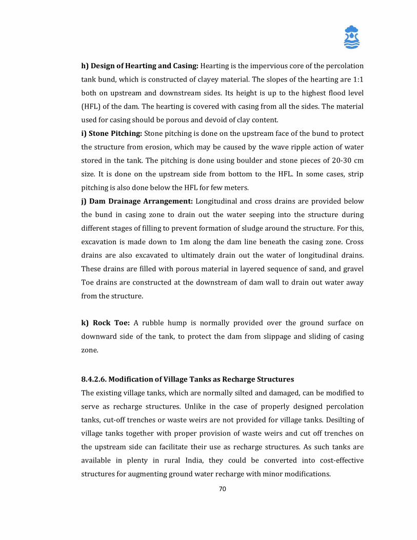
70
h) Design of Hearting and Casing: Hearting is the impervious core of the percolation
tank bund, which is constructed of clayey material. The slopes of the hearting are 1:1
both on upstream and downstream sides. Its height is up to the highest flood level
(HFL) of the dam. The hearting is covered with casing from all the sides. The material
used for casing should be porous and devoid of clay content.
i) Stone Pitching: Stone pitching is done on the upstream face of the bund to protect
the structure from erosion, which may be caused by the wave ripple action of water
stored in the tank. The pitching is done using boulder and stone pieces of 20-30 cm
size. It is done on the upstream side from bottom to the HFL. In some cases, strip
pitching is also done below the HFL for few meters.
j) Dam Drainage Arrangement: Longitudinal and cross drains are provided below
the bund in casing zone to drain out the water seeping into the structure during
different stages of filling to prevent formation of sludge around the structure. For this,
excavation is made down to 1m along the dam line beneath the casing zone. Cross
drains are also excavated to ultimately drain out the water of longitudinal drains.
These drains are filled with porous material in layered sequence of sand, and gravel
Toe drains are constructed at the downstream of dam wall to drain out water away
from the structure.
k) Rock Toe: A rubble hump is normally provided over the ground surface on
downward side of the tank, to protect the dam from slippage and sliding of casing
zone.
8.4.2.6. Modification of Village Tanks as Recharge Structures
The existing village tanks, which are normally silted and damaged, can be modified to
serve as recharge structures. Unlike in the case of properly designed percolation
tanks, cut-off trenches or waste weirs are not provided for village tanks. Desilting of
village tanks together with proper provision of waste weirs and cut off trenches on
the upstream side can facilitate their use as recharge structures. As such tanks are
available in plenty in rural India, they could be converted into cost-effective
structures for augmenting ground water recharge with minor modifications.
71
8.4.3 Sustainability structures for Surface water based sources
8.4.3.1 Ooranis
Oorani is a Tamil name for a dug-out pond that traps rain water run-off and stores it
for future use. Oorani s are formed in rural areas where ground water is either
inadequate or unfit for use. Square or rectangular, they are dug to depths of two to
five meters below the ground level. The size depends on the storage needed to meet
the demands of the village.
The earth excavated while forming the Oorani is deposited as a bund around its
perimeter, leaving a ridge of adequate width to prevent the excavated soil from
sliding in and settling at the bottom. Many oorani s have another source of water -
from a tank close by. This is in addition to the run-off from its own catchment area.
The rain water collected in the oorani is not only the surface run-off but also the
lateral sub-surface flow from the catchment area. The stored rainwater is used mainly
for drinking and often for livestock. In a village there could exist one or more oorani s,
depending on the local needs.
Almost all the drinking water Ooranis are hydrologically connected to near-by
irrigation tanks or supply channels. Even during acute scarcity villagers fill the oorani
by pumping irrigation water from the tanks. Studies show that this is done whenever
the rainfall is below normal.
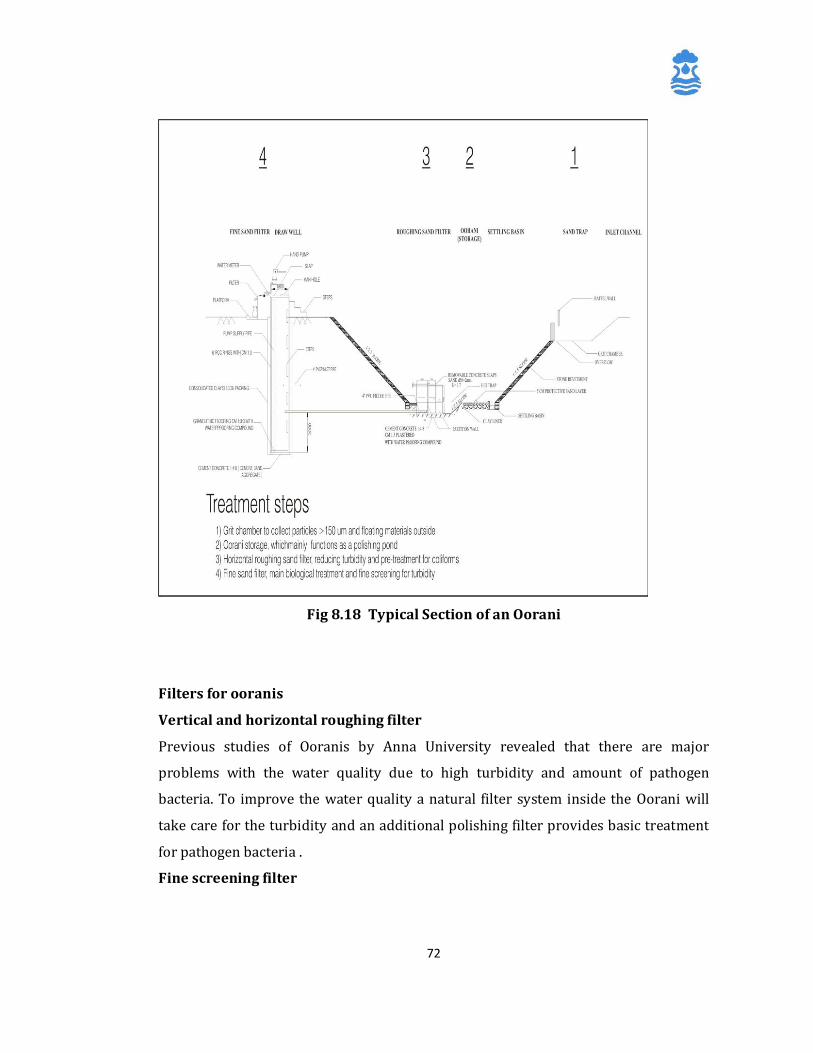
72
Fig 8.18 Typical Section of an Oorani
Filters for ooranis
Vertical and horizontal roughing filter
Previous studies of Ooranis by Anna University revealed that there are major
problems with the water quality due to high turbidity and amount of pathogen
bacteria. To improve the water quality a natural filter system inside the Oorani will
take care for the turbidity and an additional polishing filter provides basic treatment
for pathogen bacteria .
Fine screening filter
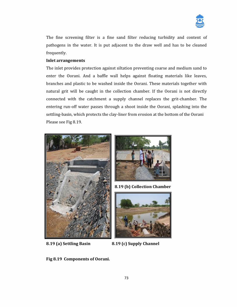
73
The fine screening filter is a fine sand filter reducing turbidity and content of
pathogens in the water. It is put adjacent to the draw well and has to be cleaned
frequently.
Inlet arrangements
The inlet provides protection against siltation preventing coarse and medium sand to
enter the Oorani. And a baffle wall helps against floating materials like leaves,
branches and plastic to be washed inside the Oorani. These materials together with
natural grit will be caught in the collection chamber. If the Oorani is not directly
connected with the catchment a supply channel replaces the grit-chamber. The
entering run-off water passes through a shoot inside the Oorani, splashing into the
settling-basin, which protects the clay-liner from erosion at the bottom of the Oorani
Please see Fig 8.19.
8.19 (b) Collection Chamber
8.19 (a) Settling Basin 8.19 (c) Supply Channel
Fig 8.19 Components of Oorani.
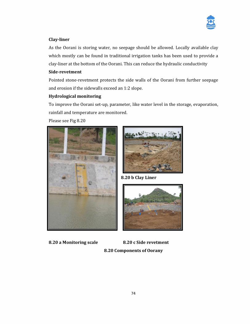
74
Clay-liner
As the Oorani is storing water, no seepage should be allowed. Locally available clay
which mostly can be found in traditional irrigation tanks has been used to provide a
clay-liner at the bottom of the Oorani. This can reduce the hydraulic conductivity
Side-revetment
Pointed stone-revetment protects the side walls of the Oorani from further seepage
and erosion if the sidewalls exceed an 1:2 slope.
Hydrological monitoring
To improve the Oorani set-up, parameter, like water level in the storage, evaporation,
rainfall and temperature are monitored.
Please see Fig 8.20
8.20 b Clay Liner
8.20 a Monitoring scale 8.20 c Side revetment
8.20 Components of Oorany
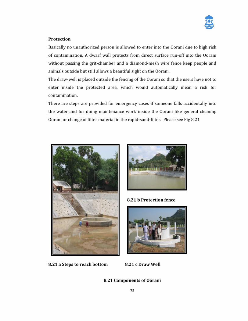
75
Protection
Basically no unauthorized person is allowed to enter into the Oorani due to high risk
of contamination. A dwarf wall protects from direct surface run-off into the Oorani
without passing the grit-chamber and a diamond-mesh wire fence keep people and
animals outside but still allows a beautiful sight on the Oorani.
The draw-well is placed outside the fencing of the Oorani so that the users have not to
enter inside the protected area, which would automatically mean a risk for
contamination.
There are steps are provided for emergency cases if someone falls accidentally into
the water and for doing maintenance work inside the Oorani like general cleaning
Oorani or change of filter material in the rapid-sand-filter. Please see Fig 8.21
8.21 b Protection fence
8.21 a Steps to reach bottom 8.21 c Draw Well
8.21 Components of Oorani
76
8.4.2.8 Stream Channel Modification / Augmentation
In areas where streams zigzag through wide valleys occupying only a small part of the
valley, the natural drainage channel can be modified with a view to increase the
infiltration by detaining stream flow and increasing the streambed area in contact
with water. For this, the channel is so modified that the flow gets spread over a wider
area, resulting in increased contact with the streambed. The methods commonly used
include a) widening, leveling, scarifying or construction of ditches in the stream
channel, b) construction of L – shaped finger levees or hook levees in the river bed at
the end of high stream flow season and c) Low head check dams which allow flood
waters to pass over them safely.
Stream channel modification can be employed in areas having influent streams that
are mostly located in piedmont regions and areas with deep water table such as arid
and semi arid regions and in valley fill deposits. The structures constructed for stream
channel modification are generally temporary, are designed to augment ground water
recharge seasonally and are likely to be destroyed by floods. These methods are
commonly applied in alluvial areas, but can also be gainfully used in hard rock areas
where thin river alluvium overlies good phreatic aquifers or the rocks are extensively
weathered or fractured in and around the stream channel. Artificial recharge through
stream channel modifications could be made more effective if surface storage dams
exist upstream of the recharge sites as they facilitate controlled release of water.
8.4.4 Subsurface Techniques
Subsurface techniques aim at recharging deeper aquifers that are overlain by
impermeable layers, preventing the infiltration from surface sources to recharge them
under natural conditions. The most common methods used for recharging such
deeper aquifers are
a) Injection wells or recharge wells,
b) Recharge pits and shafts,
77
c) Dug well recharge,
d) Borehole flooding and
e) Recharge through natural openings and cavities.
8.4.4.1 Injection Wells or Recharge Wells
Injection wells or recharge wells are structures similar to bore/tube wells but
constructed for augmenting the ground water storage in deeper aquifers through
supply of water either under gravity or under pressure. The aquifer to be replenished
is generally one with considerable desaturation due to overexploitation of ground
water. Artificial recharge of aquifers by injection wells can also be done in coastal
regions to arrest the ingress of seawater and to combat problems of land subsidence
in areas where confined aquifers are heavily pumped. In alluvial areas, injection wells
recharging a single aquifer or multiple aquifers can be constructed in a manner
similar to normal gravel packed pumping wells. However, in case of recharge wells,
cement sealing of the upper section of the wells is done to prevent the injection
pressure from causing leakage of water through the annular space of the borehole and
the well assembly. Schematics of a typical injection well in alluvial terrain are shown
in Fig.8.22. In hard rock areas, injection wells may not require casing pipes and
screens and an injection pipe with an opening against the fractures to be recharged
may be sufficient. However, properly designed injectionwells with slotted pipes
against the zones to be recharged may be required for recharging multiple aquifer
zones separated by impervious rocks.
The effectiveness of recharge through injection wells is limited by the physical
characteristics of the aquifers. Attempts to augment recharge may prove to be
counter-productive in cases where the aquifer material gets eroded due to the speed
of ground water flow, especially in unconsolidated or semi-consolidated
aquifers.Failure of confining layers may also occur if excessive pressure is applied
while injecting water. These may result in clogging and/or even collapse of the
bore/tube well.
78
8.4.4.1.1 Site Selection and Design Criteria
i) A proper understanding of the aquifer geometry is the most important factor in
implementation of successful recharge schemes through injection or recharge wells.
Detailed studies of the vertical and lateral extents of the aquifer and its characteristics
are necessary prerequisites for such schemes. Grain size distribution of granular
aquifers is another important parameter in the case of sedimentary aquifers.
ii) Recharge through injection wells increases chances of clogging of well screens and
aquifer material, resulting in decreased injection rates. Clogging may be caused by
suspended particles and air bubbles in the source water, formation of chemical
precipitates in the well, source water or aquifer material, proliferation of bacteria in
and around the injection well and swelling and dispersion of clay in the aquifer being
recharged. Clogging may be minimized by proper treatment and removal of
suspended material from source water, chemical stabilization and bacterial control.
Using non-corrosive materials for pipelines and well casings may minimize clogging
by corrosion products. Chlorination of source water prevents development of
bacterial growth. Acid treatment helps in removing calcium carbonate precipitates
from the gravel packs and aquifers. Periodic development of wells through surging,
swabbing and pumping can considerably improve the efficiency and life of injection
wells.
iii) As clogging increases the well losses considerably, the efficiency of injection wells
should be taken as 40 to 60 percent as compared to pumping wells of similar design
in the same situation.
iv) Adequate care should be taken to ensure that the water being used for recharge is
not contaminated. The water being recharged should be compatible with the
formation water to avoid any precipitation and resultant clogging. The relative
temperatures of source and formation waters also affect the recharge rate.
v) For optimum benefits, it is advisable to have injection – cum – pumping wells to be
used both for ground water recharge and extraction under favourable conditions.
79
vi ) The following considerations are important in the design of an injection well
a) The permissible pressure head of hydraulic injection in terms of water column may
be worked out as 1.2 times the depth to the topof the confined aquifer, which
represent the Hydrofracturing pressure of the confining layer. In consolidated strata,
however, this pressure is likely to be much higher. Injection of water at pressures
exceeding this limit can result in the rupture of the confining layer.
b) The rate of recharge likely to be accepted by the aquifer may be worked out on the
basis of observed discharge-drawdown relation of the existing pumping wells tapping
the same aquifer. If the aquifer parameters are known, the recharge rates may be
worked out from theoretical considerations using appropriate formulae.
However, it is always desirable to determine the actual intake rates through
injection/recharge tests in the wells.
c) The diameter of the conductor and casing pipes and the bore/tube well are to be
worked out from the rate of recharge estimated. Usually, pipes with nominal
diameters of 100mm, 150mm, 200mm and 250mm can handle flows up to 50
Cum/hr, 150 Cu m/hr, 250 Cu m/hr and 400 Cu m/hr respectively.
d) In case the well is being proposed as an injection – cum – pumping well, the well
assembly should be so designed to accommodate higher flows while pumping.
e) The inner diameter of the housing pipe has to be two nominal diameters higher
than the pump bowl size and the length of the housing pipe should be adequate to
accommodate seasonal and long-term fluctuations, interference effects of
surrounding wells in addition to expected drawdown and desired pump
submergence.
f) The casing material used for the well must be similar to the one used for production
wells and should have adequate tensile strength
and collapsing pressure. In case chemical treatment is anticipated during
development, the casing pipe and screens should be made of corrosion-resistant
material.
g) The recharge well should be designed to fully penetrate the aquifer to avoid
additional head losses due to partial penetration. In hard rocks, the top casing should
be adequate to cover the unconfined zone.
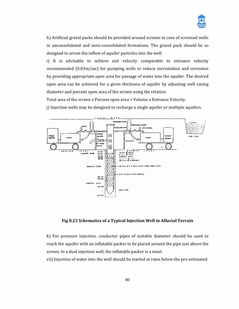
80
h) Artificial gravel packs should be provided around screens in case of screened wells
in unconsolidated and semi-consolidated formations. The gravel pack should be so
designed to arrest the inflow of aquifer particles into the well.
i) It is advisable to achieve exit velocity comparable to entrance velocity
recommended (0.03m/sec) for pumping wells to reduce incrustation and corrosion
by providing appropriate open area for passage of water into the aquifer. The desired
open area can be achieved for a given thickness of aquifer by adjusting well casing
diameter and percent open area of the screen using the relation
Total area of the screen x Percent open area = Volume x Entrance Velocity.
j) Injection wells may be designed to recharge a single aquifer or multiple aquifers.
Fig 8.22 Schematics of a Typical Injection Well in Alluvial Terrain
k) For pressure injection, conductor pipes of suitable diameter should be used to
reach the aquifer with an inflatable packer to be placed around the pipe just above the
screen. In a dual injection well, the inflatable packer is a must.
vii) Injection of water into the well should be started at rates below the pre-estimated
81
injection rate, which is then progressively increased, taking care to ensure that the
pressure build-up remains below the permissible limit. Once the maximum
permissible injection rate is attained, the well should be regularly monitored for
injection rate, injection head
and quality of water.
viii) The Specific Injection Capacity of the well, computed as the ratio of the quantum
of water applied to the head build-up in the well is determined on commissioning a
recharge well. The Specific Injection Capacity of the well reduces with time due to
clogging. When the injection rate falls below accepted economic limits, the well is
required to be redeveloped.
8.4.4.2 Gravity Head Recharge Wells
In addition to specially designed injection wells, existing dug wells and tube/bore
wells may also be alternatively used as recharge wells, as and when source water
becomes available. In areas where considerable de-saturation of aquifers have
already taken place due to over-exploitation of ground water resources resulting in
the drying up of dug wells and lowering of piezometric heads in bore/tube wells,
existing ground water abstraction structures provide a cost-effective mechanism for
artificial recharge of the phreatic or deeper aquifer zones as the case may be.
Schematics of a typical system for artificial recharge through dug wells are shown in
Fig.8.23.
8.4.4.2.1 Site Characteristics and Design Guidelines
i) In areas where excess surface water is available during rainy season and the
phreatic aquifers remain unsaturated, surface water can be pumped into the dug
wells for augmentation of ground water resources.
ii) Wells with higher yields before getting dried up due to the desaturation
of aquifers should be selected for recharge as they prove to be more suitable for
ground water recharge when compared to lowyielding wells.
82
iii) The recharge head available in gravity head recharge wells is the elevation
difference between the surface water level in the feeder reservoir /tank and the
elevation of water table or piezometric head.
The recharge rates in such cases are likely to be much less when compared to
pressure injection and will also keep on reducing with build-up of the water table in
the aquifer.
iv) Pumping of wells during periods of non-availability of recharge water helps in
removing the silt that may enter the well during recharge. However, more rigorous
development may be essential in the case of deep bore/tube wells
v) Care should be taken to ensure that the source water is adequately filtered and
disinfected when existing wells are being used forrecharge. The recharge water
should be guided through a pipe to the bottom of well, below the water level to avoid
scouring of bottom and
entrapment of air bubbles in the aquifer.

83
Fig 8.23 Schematics of a Typical System for Artificial Recharge through Dug
Well.
8.4.4.3 Recharge Pits and Shafts
Recharge pits and shafts are artificial recharge structures commonly used for
recharging shallow phreatic aquifers, which are not in hydraulic connection with
surface water due to the presence of impermeable layers. They do not necessarily
penetrate or reach the unconfined aquifers like gravity head recharge wells and the
recharging water has to infiltrate through the vadose zone.
8.4.4.3.1 Recharge Pits: Recharge pits are normally excavated pits, which are
sufficiently deep to penetrate the low-permeability layers overlying the unconfined
aquifers (Fig.8.24). These Recharge Pits shall be very useful as Recharge structures
for shallow Handpumps. They are similar to recharge basins in principle, with the
only difference being that they are deeper and have restricted bottom area. In many
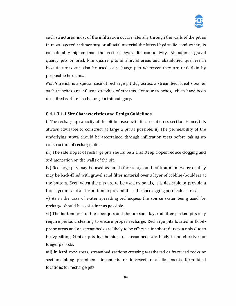
84
such structures, most of the infiltration occurs laterally through the walls of the pit as
in most layered sedimentary or alluvial material the lateral hydraulic conductivity is
considerably higher than the vertical hydraulic conductivity. Abandoned gravel
quarry pits or brick kiln quarry pits in alluvial areas and abandoned quarries in
basaltic areas can also be used as recharge pits wherever they are underlain by
permeable horizons.
Nalah trench is a special case of recharge pit dug across a streambed. Ideal sites for
such trenches are influent stretches of streams. Contour trenches, which have been
described earlier also belongs to this category.
8.4.4.3.1.1 Site Characteristics and Design Guidelines
i) The recharging capacity of the pit increase with its area of cross section. Hence, it is
always advisable to construct as large a pit as possible. ii) The permeability of the
underlying strata should be ascertained through infiltration tests before taking up
construction of recharge pits.
iii) The side slopes of recharge pits should be 2:1 as steep slopes reduce clogging and
sedimentation on the walls of the pit.
iv) Recharge pits may be used as ponds for storage and infiltration of water or they
may be back-filled with gravel sand filter material over a layer of cobbles/boulders at
the bottom. Even when the pits are to be used as ponds, it is desirable to provide a
thin layer of sand at the bottom to prevent the silt from clogging permeable strata.
v) As in the case of water spreading techniques, the source water being used for
recharge should be as silt-free as possible.
vi) The bottom area of the open pits and the top sand layer of filter-packed pits may
require periodic cleaning to ensure proper recharge. Recharge pits located in flood-
prone areas and on streambeds are likely to be effective for short duration only due to
heavy silting. Similar pits by the sides of streambeds are likely to be effective for
longer periods.
vii) In hard rock areas, streambed sections crossing weathered or fractured rocks or
sections along prominent lineaments or intersection of lineaments form ideal
locations for recharge pits.
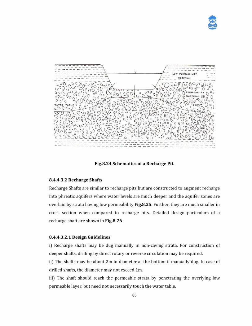
85
Fig.8.24 Schematics of a Recharge Pit.
8.4.4.3.2 Recharge Shafts
Recharge Shafts are similar to recharge pits but are constructed to augment recharge
into phreatic aquifers where water levels are much deeper and the aquifer zones are
overlain by strata having low permeability Fig.8.25. Further, they are much smaller in
cross section when compared to recharge pits. Detailed design particulars of a
recharge shaft are shown in Fig.8.26
8.4.4.3.2.1 Design Guidelines
i) Recharge shafts may be dug manually in non-caving strata. For construction of
deeper shafts, drilling by direct rotary or reverse circulation may be required.
ii) The shafts may be about 2m in diameter at the bottom if manually dug. In case of
drilled shafts, the diameter may not exceed 1m.
iii) The shaft should reach the permeable strata by penetrating the overlying low
permeable layer, but need not necessarily touch the water table.
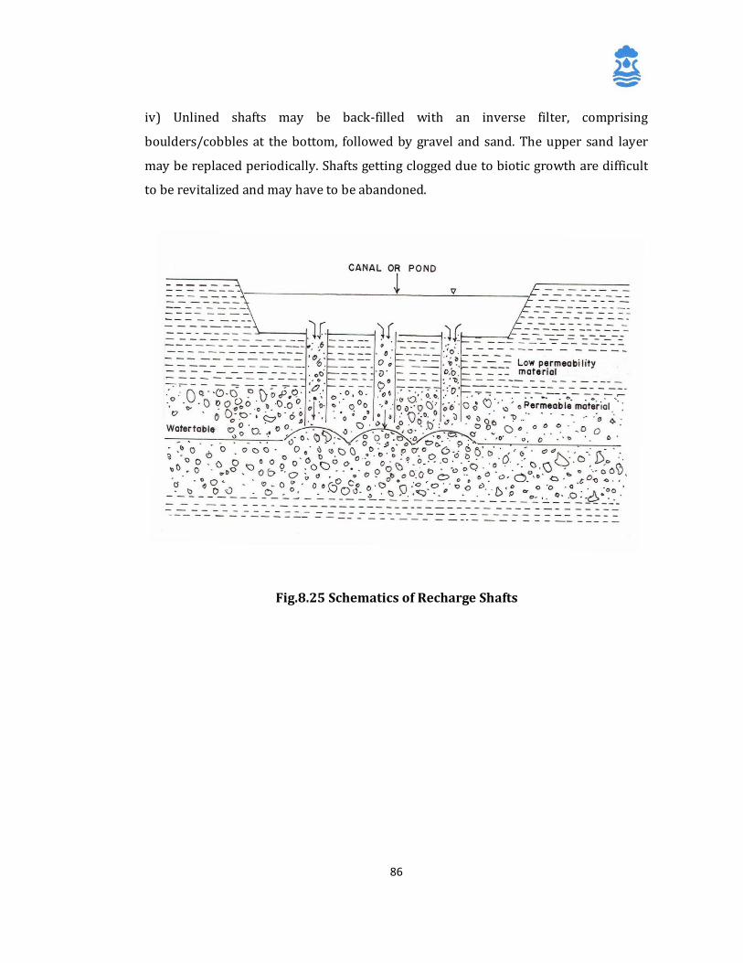
86
iv) Unlined shafts may be back-filled with an inverse filter, comprising
boulders/cobbles at the bottom, followed by gravel and sand. The upper sand layer
may be replaced periodically. Shafts getting clogged due to biotic growth are difficult
to be revitalized and may have to be abandoned.
Fig.8.25 Schematics of Recharge Shafts
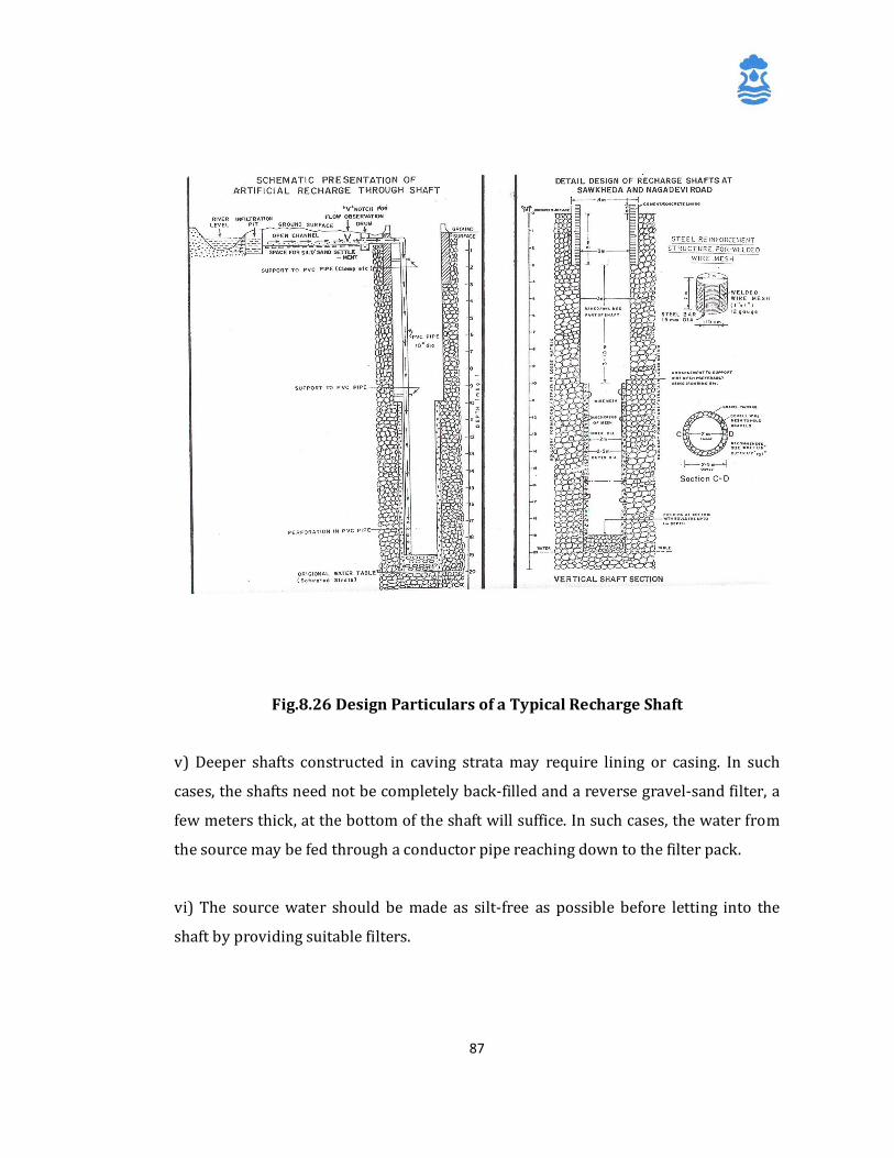
87
Fig.8.26 Design Particulars of a Typical Recharge Shaft
v) Deeper shafts constructed in caving strata may require lining or casing. In such
cases, the shafts need not be completely back-filled and a reverse gravel-sand filter, a
few meters thick, at the bottom of the shaft will suffice. In such cases, the water from
the source may be fed through a conductor pipe reaching down to the filter pack.
vi) The source water should be made as silt-free as possible before letting into the
shaft by providing suitable filters.
88
8.5 Indirect Methods
Indirect methods for artificial recharge to ground water does not involve direct
supply of water for recharging aquifers, but aim at recharging aquifers through
indirect means. The most common methods in this category are induced recharge
from surface water sources and aquifer modification techniques.
8.5.1 Induced Recharge
Induced recharge involves pumping water from an aquifer, which is hydraulically
connected with surface water to induce recharge to the ground water reservoir. Once
hydraulic connection gets established by the interception of the cone of depression
and the river recharge boundary, the surface water sources starts providing part of
the pumping yield (Fig.8.27). Induced recharge, under favorable hydrogeological
conditions, can be used for improving the quality of surface water resources due to its
passage through the aquifer material. Collector wells and infiltration galleries, used
for obtaining very large water supplies from riverbeds, lakebeds and waterlogged
areas also function on the principle of induced recharge.
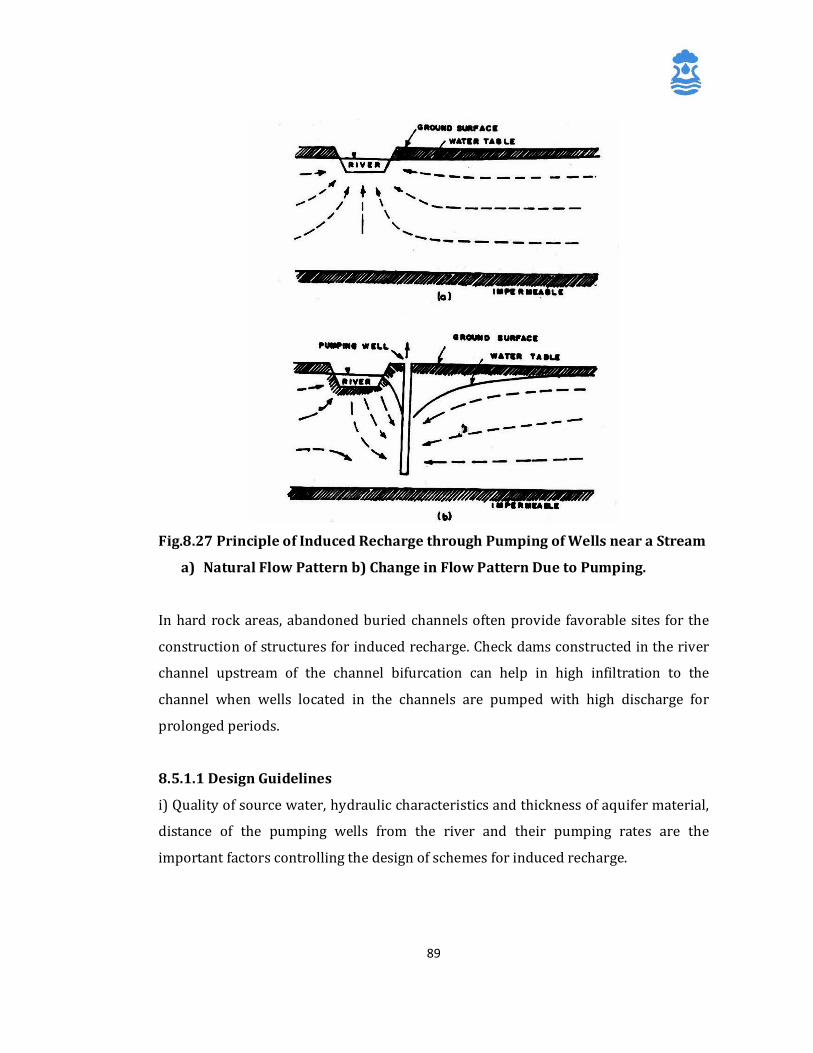
89
Fig.8.27 Principle of Induced Recharge through Pumping of Wells near a Stream
a) Natural Flow Pattern b) Change in Flow Pattern Due to Pumping.
In hard rock areas, abandoned buried channels often provide favorable sites for the
construction of structures for induced recharge. Check dams constructed in the river
channel upstream of the channel bifurcation can help in high infiltration to the
channel when wells located in the channels are pumped with high discharge for
prolonged periods.
8.5.1.1 Design Guidelines
i) Quality of source water, hydraulic characteristics and thickness of aquifer material,
distance of the pumping wells from the river and their pumping rates are the
important factors controlling the design of schemes for induced recharge.
90
ii) For implementation of successful induced recharge schemes from stream channels,
pumping wells should be selected at sites where water in the streams has sufficient
velocity to prevent silt deposition.
iii) Dredging of channel bottom in the vicinity of the existing pumping wells may have
to be carried our periodically to remove organic matter and impervious fine material
from the beds of the channel.
iv) For wells constructed in unconfined alluvial strata for induced recharge, the lower
one-third of the wells may be screened to have optimum drawdowns. In highly
fractured consolidated rocks, dug wells penetrating the entire thickness of the aquifer
should be constructed with lining above the water table zone and the curbing height
well above the High Flow Level (HFL) of the stream.
8.5.2 Aquifer Modification Techniques
These techniques modify the aquifer characteristics to increase its capacity to store
and transmit water through artificial means. The most important techniques under
this category are bore blasting techniques and hydrofracturing techniques. Though
they are yield augmentation techniques rather than artificial recharge structures, they
are also being considered as artificial recharge structures owing to the resultant
increase in the storage of ground water in the aquifers.
8.5.2.1 Borewell Blasting Technique:
Bore blast technique is adopted to artificially create more storage space for
Groundwater in massive and crystalline hard rocks by fracturing the bed rocks.
Hydrogeological survey is carried out to locate such area where the rock can be
blasted to develop cracks below the zone of weathering. A series of Boreholes are
drilled near the drinking water source borewell, which is targeted to be benefitted.
Suitable type of slurry explosive is lowered in the boreholes and is blasted using
detonating cord and electrical detonators. About 5 to 6 boreholes are blasted
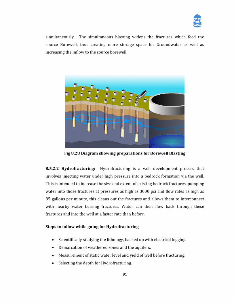
91
simultaneously. The simultaneous blasting widens the fractures which feed the
source Borewell, thus creating more storage space for Groundwater as well as
increasing the inflow to the source borewell.
Fig 8.28 Diagram showing preparations for Borewell Blasting
8.5.2.2 Hydrofracturing: Hydrofracturing is a well development process that
involves injecting water under high pressure into a bedrock formation via the well.
This is intended to increase the size and extent of existing bedrock fractures, pumping
water into those fractures at pressures as high as 3000 psi and flow rates as high as
85 gallons per minute, this cleans out the fractures and allows them to interconnect
with nearby water bearing fractures. Water can then flow back through these
fractures and into the well at a faster rate than before.
Steps to follow while going for Hydrofracturing
• Scientifically studying the lithology, backed up with electrical logging.
• Demarcation of weathered zones and the aquifers.
• Measurement of static water level and yield of well before fracturing.
• Selecting the depth for Hydrofracturing.
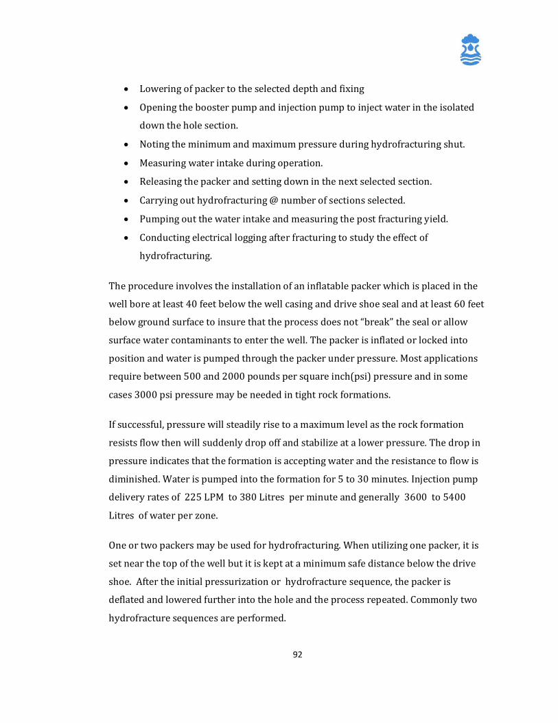
92
• Lowering of packer to the selected depth and fixing
• Opening the booster pump and injection pump to inject water in the isolated
down the hole section.
• Noting the minimum and maximum pressure during hydrofracturing shut.
• Measuring water intake during operation.
• Releasing the packer and setting down in the next selected section.
• Carrying out hydrofracturing @ number of sections selected.
• Pumping out the water intake and measuring the post fracturing yield.
• Conducting electrical logging after fracturing to study the effect of
hydrofracturing.
The procedure involves the installation of an inflatable packer which is placed in the
well bore at least 40 feet below the well casing and drive shoe seal and at least 60 feet
below ground surface to insure that the process does not “break” the seal or allow
surface water contaminants to enter the well. The packer is inflated or locked into
position and water is pumped through the packer under pressure. Most applications
require between 500 and 2000 pounds per square inch(psi) pressure and in some
cases 3000 psi pressure may be needed in tight rock formations.
If successful, pressure will steadily rise to a maximum level as the rock formation
resists flow then will suddenly drop off and stabilize at a lower pressure. The drop in
pressure indicates that the formation is accepting water and the resistance to flow is
diminished. Water is pumped into the formation for 5 to 30 minutes. Injection pump
delivery rates of 225 LPM to 380 Litres per minute and generally 3600 to 5400
Litres of water per zone.
One or two packers may be used for hydrofracturing. When utilizing one packer, it is
set near the top of the well but it is kept at a minimum safe distance below the drive
shoe. After the initial pressurization or hydrofracture sequence, the packer is
deflated and lowered further into the hole and the process repeated. Commonly two
hydrofracture sequences are performed.
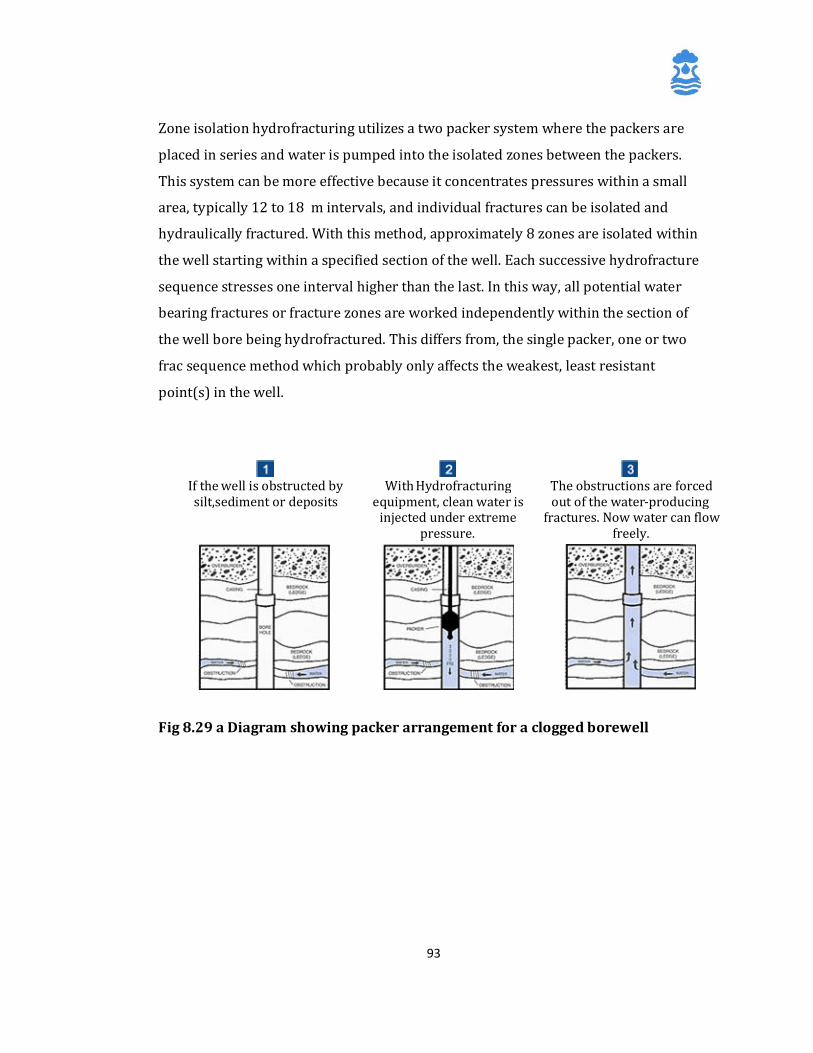
93
Zone isolation hydrofracturing utilizes a two packer system where the packers are
placed in series and water is pumped into the isolated zones between the packers.
This system can be more effective because it concentrates pressures within a small
area, typically 12 to 18 m intervals, and individual fractures can be isolated and
hydraulically fractured. With this method, approximately 8 zones are isolated within
the well starting within a specified section of the well. Each successive hydrofracture
sequence stresses one interval higher than the last. In this way, all potential water
bearing fractures or fracture zones are worked independently within the section of
the well bore being hydrofractured. This differs from, the single packer, one or two
frac sequence method which probably only affects the weakest, least resistant
point(s) in the well.
Fig 8.29 a Diagram showing packer arrangement for a clogged borewell
If the well is obstructed by silt,sediment or deposits
With Hydrofracturing
equipment, clean water is injected under extreme
pressure.
The obstructions are forced out of the water- producing
fractures. Now water can flow freely.
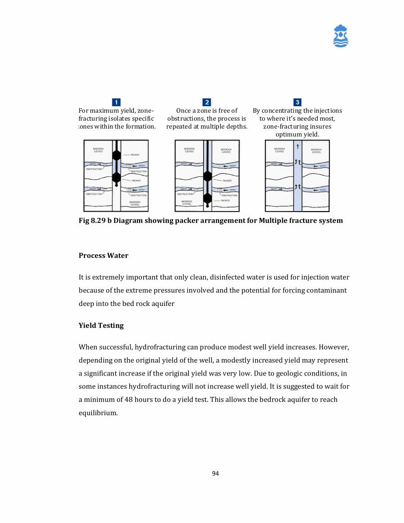
94
Fig 8.29 b Diagram showing packer arrangement for Multiple fracture system
Process Water
It is extremely important that only clean, disinfected water is used for injection water
because of the extreme pressures involved and the potential for forcing contaminant
deep into the bed rock aquifer
Yield Testing
When successful, hydrofracturing can produce modest well yield increases. However,
depending on the original yield of the well, a modestly increased yield may represent
a significant increase if the original yield was very low. Due to geologic conditions, in
some instances hydrofracturing will not increase well yield. It is suggested to wait for
a minimum of 48 hours to do a yield test. This allows the bedrock aquifer to reach
equilibrium.
For maximum yield, zone-fracturing isolates specific
zones within the formation.
Once a zone is free of
obstructions, the process is repeated at multiple depths.
By concentrating the injections
to where it's needed most, zone-fracturing insures
optimum yield.
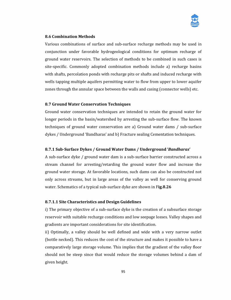
95
8.6 Combination Methods
Various combinations of surface and sub-surface recharge methods may be used in
conjunction under favorable hydrogeological conditions for optimum recharge of
ground water reservoirs. The selection of methods to be combined in such cases is
site-specific. Commonly adopted combination methods include a) recharge basins
with shafts, percolation ponds with recharge pits or shafts and induced recharge with
wells tapping multiple aquifers permitting water to flow from upper to lower aquifer
zones through the annular space between the walls and casing (connector wells) etc.
8.7 Ground Water Conservation Techniques
Ground water conservation techniques are intended to retain the ground water for
longer periods in the basin/watershed by arresting the sub-surface flow. The known
techniques of ground water conservation are a) Ground water dams / sub-surface
dykes / Underground ‘Bandharas’ and b) Fracture sealing Cementation techniques.
8.7.1 Sub-Surface Dykes / Ground Water Dams / Underground ‘Bandharas’
A sub-surface dyke / ground water dam is a sub-surface barrier constructed across a
stream channel for arresting/retarding the ground water flow and increase the
ground water storage. At favorable locations, such dams can also be constructed not
only across streams, but in large areas of the valley as well for conserving ground
water. Schematics of a typical sub-surface dyke are shown in Fig.8.26
8.7.1.1 Site Characteristics and Design Guidelines
i) The primary objective of a sub-surface dyke is the creation of a subsurface storage
reservoir with suitable recharge conditions and low seepage losses. Valley shapes and
gradients are important considerations for site identification.
ii) Optimally, a valley should be well defined and wide with a very narrow outlet
(bottle necked). This reduces the cost of the structure and makes it possible to have a
comparatively large storage volume. This implies that the gradient of the valley floor
should not be steep since that would reduce the storage volumes behind a dam of
given height.
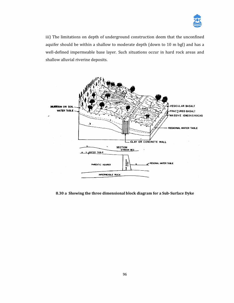
96
iii) The limitations on depth of underground construction deem that the unconfined
aquifer should be within a shallow to moderate depth (down to 10 m bgl) and has a
well-defined impermeable base layer. Such situations occur in hard rock areas and
shallow alluvial riverine deposits.
8.30 a Showing the three dimensional block diagram for a Sub-Surface Dyke
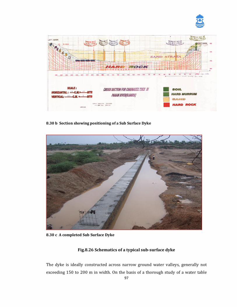
97
8.30 b Section showing positioning of a Sub Surface Dyke
8.30 c A completed Sub Surface Dyke
Fig.8.26 Schematics of a typical sub-surface dyke
The dyke is ideally constructed across narrow ground water valleys, generally not
exceeding 150 to 200 m in width. On the basis of a thorough study of a water table
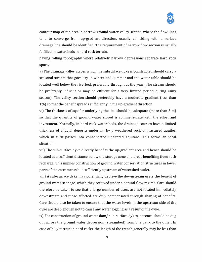
98
contour map of the area, a narrow ground water valley section where the flow lines
tend to converge from up-gradient direction, usually coinciding with a surface
drainage line should be identified. The requirement of narrow flow section is usually
fulfilled in watersheds in hard rock terrain.
having rolling topography where relatively narrow depressions separate hard rock
spurs.
v) The drainage valley across which the subsurface dyke is constructed should carry a
seasonal stream that goes dry in winter and summer and the water table should be
located well below the riverbed, preferably throughout the year (The stream should
be preferably influent or may be effluent for a very limited period during rainy
season). The valley section should preferably have a moderate gradient (less than
1%) so that the benefit spreads sufficiently in the up-gradient direction.
vi) The thickness of aquifer underlying the site should be adequate (more than 5 m)
so that the quantity of ground water stored is commensurate with the effort and
investment. Normally, in hard rock watersheds, the drainage courses have a limited
thickness of alluvial deposits underlain by a weathered rock or fractured aquifer,
which in turn passes into consolidated unaltered aquitard. This forms an ideal
situation.
vii) The sub-surface dyke directly benefits the up-gradient area and hence should be
located at a sufficient distance below the storage zone and areas benefiting from such
recharge. This implies construction of ground water conservation structures in lower
parts of the catchments but sufficiently upstream of watershed outlet.
viii) A sub-surface dyke may potentially deprive the downstream users the benefit of
ground water seepage, which they received under a natural flow regime. Care should
therefore be taken to see that a large number of users are not located immediately
downstream and those affected are duly compensated through sharing of benefits.
Care should also be taken to ensure that the water levels in the upstream side of the
dyke are deep enough not to cause any water logging as a result of the dyke.
ix) For construction of ground water dam/ sub-surface dykes, a trench should be dug
out across the ground water depression (streambed) from one bank to the other. In
case of hilly terrain in hard rocks, the length of the trench generally may be less than
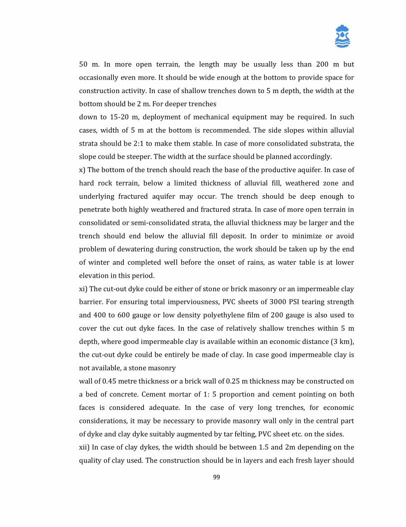
99
50 m. In more open terrain, the length may be usually less than 200 m but
occasionally even more. It should be wide enough at the bottom to provide space for
construction activity. In case of shallow trenches down to 5 m depth, the width at the
bottom should be 2 m. For deeper trenches
down to 15-20 m, deployment of mechanical equipment may be required. In such
cases, width of 5 m at the bottom is recommended. The side slopes within alluvial
strata should be 2:1 to make them stable. In case of more consolidated substrata, the
slope could be steeper. The width at the surface should be planned accordingly.
x) The bottom of the trench should reach the base of the productive aquifer. In case of
hard rock terrain, below a limited thickness of alluvial fill, weathered zone and
underlying fractured aquifer may occur. The trench should be deep enough to
penetrate both highly weathered and fractured strata. In case of more open terrain in
consolidated or semi-consolidated strata, the alluvial thickness may be larger and the
trench should end below the alluvial fill deposit. In order to minimize or avoid
problem of dewatering during construction, the work should be taken up by the end
of winter and completed well before the onset of rains, as water table is at lower
elevation in this period.
xi) The cut-out dyke could be either of stone or brick masonry or an impermeable clay
barrier. For ensuring total imperviousness, PVC sheets of 3000 PSI tearing strength
and 400 to 600 gauge or low density polyethylene film of 200 gauge is also used to
cover the cut out dyke faces. In the case of relatively shallow trenches within 5 m
depth, where good impermeable clay is available within an economic distance (3 km),
the cut-out dyke could be entirely be made of clay. In case good impermeable clay is
not available, a stone masonry
wall of 0.45 metre thickness or a brick wall of 0.25 m thickness may be constructed on
a bed of concrete. Cement mortar of 1: 5 proportion and cement pointing on both
faces is considered adequate. In the case of very long trenches, for economic
considerations, it may be necessary to provide masonry wall only in the central part
of dyke and clay dyke suitably augmented by tar felting, PVC sheet etc. on the sides.
xii) In case of clay dykes, the width should be between 1.5 and 2m depending on the
quality of clay used. The construction should be in layers and each fresh layer should
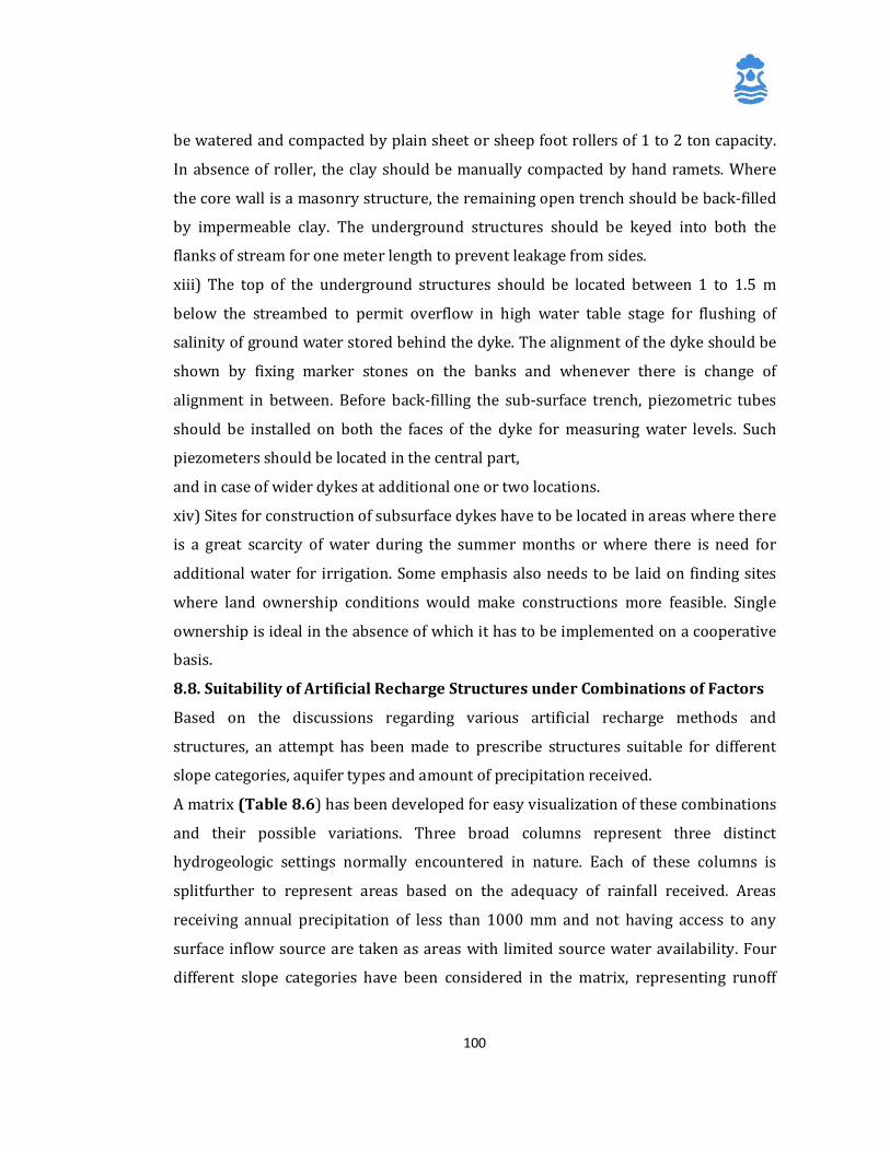
100
be watered and compacted by plain sheet or sheep foot rollers of 1 to 2 ton capacity.
In absence of roller, the clay should be manually compacted by hand ramets. Where
the core wall is a masonry structure, the remaining open trench should be back-filled
by impermeable clay. The underground structures should be keyed into both the
flanks of stream for one meter length to prevent leakage from sides.
xiii) The top of the underground structures should be located between 1 to 1.5 m
below the streambed to permit overflow in high water table stage for flushing of
salinity of ground water stored behind the dyke. The alignment of the dyke should be
shown by fixing marker stones on the banks and whenever there is change of
alignment in between. Before back-filling the sub-surface trench, piezometric tubes
should be installed on both the faces of the dyke for measuring water levels. Such
piezometers should be located in the central part,
and in case of wider dykes at additional one or two locations.
xiv) Sites for construction of subsurface dykes have to be located in areas where there
is a great scarcity of water during the summer months or where there is need for
additional water for irrigation. Some emphasis also needs to be laid on finding sites
where land ownership conditions would make constructions more feasible. Single
ownership is ideal in the absence of which it has to be implemented on a cooperative
basis.
8.8. Suitability of Artificial Recharge Structures under Combinations of Factors
Based on the discussions regarding various artificial recharge methods and
structures, an attempt has been made to prescribe structures suitable for different
slope categories, aquifer types and amount of precipitation received.
A matrix (Table 8.6) has been developed for easy visualization of these combinations
and their possible variations. Three broad columns represent three distinct
hydrogeologic settings normally encountered in nature. Each of these columns is
splitfurther to represent areas based on the adequacy of rainfall received. Areas
receiving annual precipitation of less than 1000 mm and not having access to any
surface inflow source are taken as areas with limited source water availability. Four
different slope categories have been considered in the matrix, representing runoff
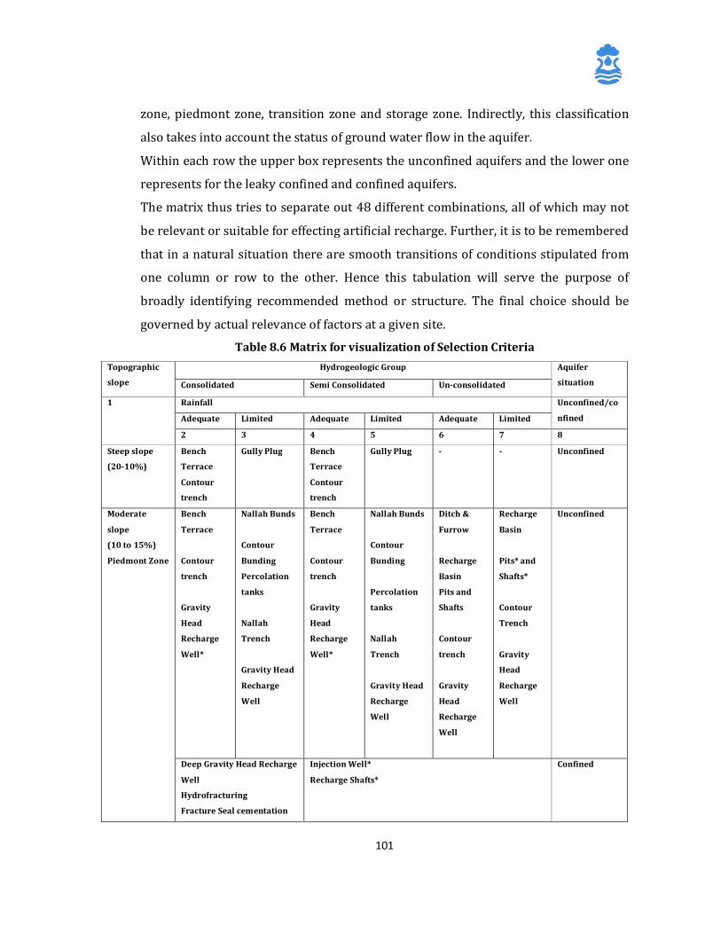
101
zone, piedmont zone, transition zone and storage zone. Indirectly, this classification
also takes into account the status of ground water flow in the aquifer.
Within each row the upper box represents the unconfined aquifers and the lower one
represents for the leaky confined and confined aquifers.
The matrix thus tries to separate out 48 different combinations, all of which may not
be relevant or suitable for effecting artificial recharge. Further, it is to be remembered
that in a natural situation there are smooth transitions of conditions stipulated from
one column or row to the other. Hence this tabulation will serve the purpose of
broadly identifying recommended method or structure. The final choice should be
governed by actual relevance of factors at a given site.
Table 8.6 Matrix for visualization of Selection Criteria Topographic
slope
Hydrogeologic Group Aquifer
situation Consolidated Semi Consolidated Un-consolidated
1 Rainfall Unconfined/co
nfined Adequate Limited Adequate Limited Adequate Limited
2 3 4 5 6 7 8
Steep slope
(20-10%)
Bench
Terrace
Contour
trench
Gully Plug Bench
Terrace
Contour
trench
Gully Plug - - Unconfined
Moderate
slope
(10 to 15%)
Piedmont Zone
Bench
Terrace
Contour
trench
Gravity
Head
Recharge
Well*
Nallah Bunds
Contour
Bunding
Percolation
tanks
Nallah
Trench
Gravity Head
Recharge
Well
Bench
Terrace
Contour
trench
Gravity
Head
Recharge
Well*
Nallah Bunds
Contour
Bunding
Percolation
tanks
Nallah
Trench
Gravity Head
Recharge
Well
Ditch &
Furrow
Recharge
Basin
Pits and
Shafts
Contour
trench
Gravity
Head
Recharge
Well
Recharge
Basin
Pits* and
Shafts*
Contour
Trench
Gravity
Head
Recharge
Well
Unconfined
Deep Gravity Head Recharge
Well
Hydrofracturing
Fracture Seal cementation
Injection Well*
Recharge Shafts*
Confined
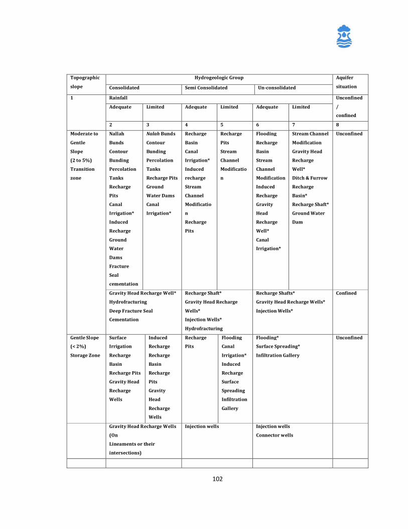
102
Topographic
slope
Hydrogeologic Group Aquifer
situation Consolidated Semi Consolidated Un-consolidated
1 Rainfall Unconfined
/
confined
Adequate Limited Adequate Limited Adequate Limited
2 3 4 5 6 7 8
Moderate to
Gentle
Slope
(2 to 5%)
Transition
zone
Nallah
Bunds
Contour
Bunding
Percolation
Tanks
Recharge
Pits
Canal
Irrigation*
Induced
Recharge
Ground
Water
Dams
Fracture
Seal
cementation
Nalah Bunds
Contour
Bunding
Percolation
Tanks
Recharge Pits
Ground
Water Dams
Canal
Irrigation*
Recharge
Basin
Canal
Irrigation*
Induced
recharge
Stream
Channel
Modificatio
n
Recharge
Pits
Recharge
Pits
Stream
Channel
Modificatio
n
Flooding
Recharge
Basin
Stream
Channel
Modification
Induced
Recharge
Gravity
Head
Recharge
Well*
Canal
Irrigation*
Stream Channel
Modification
Gravity Head
Recharge
Well*
Ditch & Furrow
Recharge
Basin*
Recharge Shaft*
Ground Water
Dam
Unconfined
Gravity Head Recharge Well*
Hydrofracturing
Deep Fracture Seal
Cementation
Recharge Shaft*
Gravity Head Recharge
Wells*
Injection Wells*
Hydrofracturing
Recharge Shafts*
Gravity Head Recharge Wells*
Injection Wells*
Confined
Gentle Slope
(< 2%)
Storage Zone
Surface
Irrigation
Recharge
Basin
Recharge Pits
Gravity Head
Recharge
Wells
Induced
Recharge
Recharge
Basin
Recharge
Pits
Gravity
Head
Recharge
Wells
Recharge
Pits
Flooding
Canal
Irrigation*
Induced
Recharge
Surface
Spreading
Infiltration
Gallery
Flooding*
Surface Spreading*
Infiltration Gallery
Unconfined
Gravity Head Recharge Wells
(On
Lineaments or their
intersections)
Injection wells Injection wells
Connector wells

103
Note: Rainfall is considered ‘adequate’ if annual precipitation is more than 1000 mm.
* Indicate availability of source water supply through canals, trans-basin transfer or
treated wastewater.
(Modified After: Manual on Artificial Recharge of Ground Water, CGWB (1994).
104
9 Rooftop Rainwater Harvesting In most of the rural areas, ground water is the major source of drinking water. In
earlier days, open wells and ponds that belonged to the community were the source of
drinking water supply. With the advent of bore well technology and progress made in
rural electrification, the scenario of rural water supply has considerably changed. The
traditional methods and practices have given way to hand pumps and power pump
schemes. Government organisations have given priority to provide protected water
supply to the villages through rural water supply schemes. Bore wells are drilled and
water from over-head tanks is distributed through supply mains. Statistics reveal that
more than 85% of rural water supply is from the ground water sources at present.
Indiscriminate exploitation of ground water and the decline in ground water levels
have rendered many bore wells dry either seasonally or through out the year. To
overcome such a situation, bore wells and tube wells are now being drilled to greater
depths, often tapping ground water from deep aquifers hitherto considered ‘static’.
Discharge of untreated effluents into surface water streams and lakes by industries
has resulted not only in contaminating the surface water resources, but also the
ground water bodies. In coastal areas, over exploitation of ground water has resulted
in seawater intrusion, rendering ground water sources saline in some areas.
Identification and promotion of simple, reliable and environmental friendly
technologies for augmentation of ground water resources are necessary to overcome
the above problems and to ensure the long-term sustainability of our precious ground
water resources. Reviving the traditional practices of rainwater harvesting along
scientific lines can go a long way in preventing a serious water crisis in the major part
of our country in the years to come.
9.1 Concept of Roof Top Rainwater Harvesting
The concept of rainwater harvesting involves ‘tapping the rainwater where it falls’. A
major portion of rainwater that falls on the earth’s surface runs off into streams and
rivers and finally into the sea. An average of 8-12 percent of the total rainfall recharge
only is considered to recharge the aquifers. The technique of rainwater harvesting
involves collecting the rain from localized catchment surfaces such as roofs, plain /
sloping surfaces etc., either for direct use or to augment the ground water resources

105
depending on local conditions. Construction of small barriers across small streams to
check and store the running water also can be considered as water harvesting.
Among various techniques of water harvesting, harvesting water from roof tops needs
special attention because of the following advantages:
a) Roof top rainwater harvesting is one of the appropriate options for augmenting
ground water recharge/ storage in urban areas where natural recharge is
considerably reduced due to increased urban activities and not much land is available
for implementing any other artificial recharge measure. Roof top rainwater
harvesting can supplement the domestic requirements in rural areas as well.
b) Rainwater runoff which otherwise flows through sewers and storm drains and is
wasted, can be harvested and utilized.
c) Rainwater is bacteriologically safe, free from organic matter and is soft in nature.
d) It helps in reducing the frequent drainage congestion and flooding during heavy
rains in urban areas where availability of open surfaces is limited and surface runoff
is quite high.
e) It improves the quality of ground water through dilution.
f) The harnessed rainwater can be utilized at the time of need.
g) The structures required for harvesting rainwater are simple, economical and
ecofriendly.
h) Roof catchments are relatively cleaner and free from contamination compared to
the ground level catchments.
i) Losses from roof catchments are much less when compared to other catchments.
Collection of rainwater from roof tops for domestic needs is popular in some parts of
India. The simplest method of roof top rainwater harvesting is the collection of
rainwater in a large pot/vessel kept beneath the edge of the roof. The water thus
collected can meet the immediate domestic needs. Tanks made of iron sheets, cement
or bricks can also be used for storing water. In this method, water is collected from
roofs using drain pipes/gutters fixed to roof edge. Though the practice of roof top
rainwater harvesting is an age-old one, systematic
collection and storage of water to meet the drinking water needs has become popular
only recently. The popularity of this practice is limited by the costs involved in
106
collection of water by gutters/pipes and its storage in underground tanks made of
iron or brick. Use of Ferro-cement technology in construction and maintenance of
storage tanks has become popular in recent years as the strength and durability of
ferrocement structures have been found to make the schemes cost-effective.
Rainwater harvesting practices vary widely in size, type of construction material used
and methods of collection and storage. Easy availability of know-how on systematic
and economic methods of construction will encourage the user households to adopt
this practice. There is also a need for creating awareness and for development of
simple techniques of construction/fabrication of the components of rainwater
harvesting system for popularising this technique as a potential alternative source of
drinking water, at least for part of the year.
9.2 Components of Roof Top Rainwater Harvesting System
In a typical domestic roof top rainwater harvesting system, rainwater from the roof is
collected in a storage vessel or tank for use during periods of scarcity. Such systems
are usually designed to support the drinking and cooking needs of the family and
comprise a roof, a storage tank and guttering to transport the water from the roof to
the storage tank. In addition, a first flush system to divert the dirty water, which
contains debris, collected on the roof during non-rainy periods and a filter unit to
remove debris and contaminants before water enters the storage tank are also
provided. Therefore, a typical Roof top Rainwater Harvesting System (Fig.9.1)
comprises following components:
§ Roof catchment.
§ Drain pipes
§ Gutters
§ Down pipe
§ First flush pipe.
§ Filter unit
§ Storage tank.
§ Collection sump.
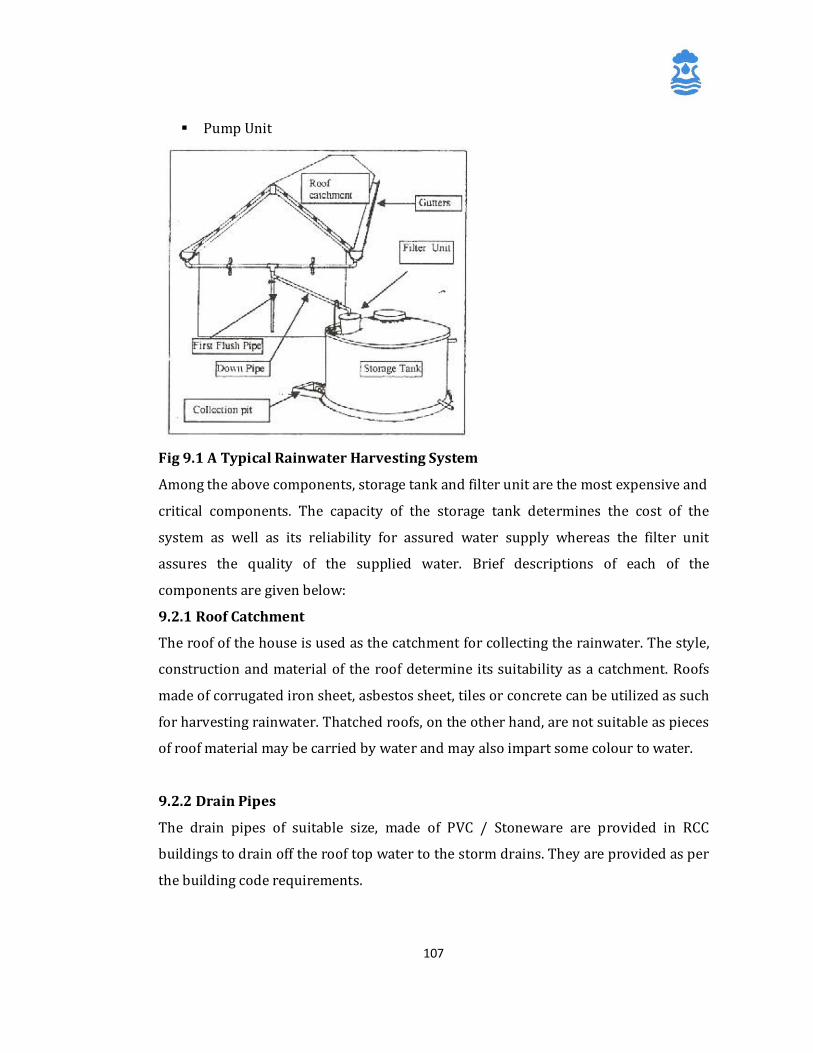
107
§ Pump Unit
Fig 9.1 A Typical Rainwater Harvesting System Among the above components, storage tank and filter unit are the most expensive and
critical components. The capacity of the storage tank determines the cost of the
system as well as its reliability for assured water supply whereas the filter unit
assures the quality of the supplied water. Brief descriptions of each of the
components are given below:
9.2.1 Roof Catchment
The roof of the house is used as the catchment for collecting the rainwater. The style,
construction and material of the roof determine its suitability as a catchment. Roofs
made of corrugated iron sheet, asbestos sheet, tiles or concrete can be utilized as such
for harvesting rainwater. Thatched roofs, on the other hand, are not suitable as pieces
of roof material may be carried by water and may also impart some colour to water.
9.2.2 Drain Pipes
The drain pipes of suitable size, made of PVC / Stoneware are provided in RCC
buildings to drain off the roof top water to the storm drains. They are provided as per
the building code requirements.
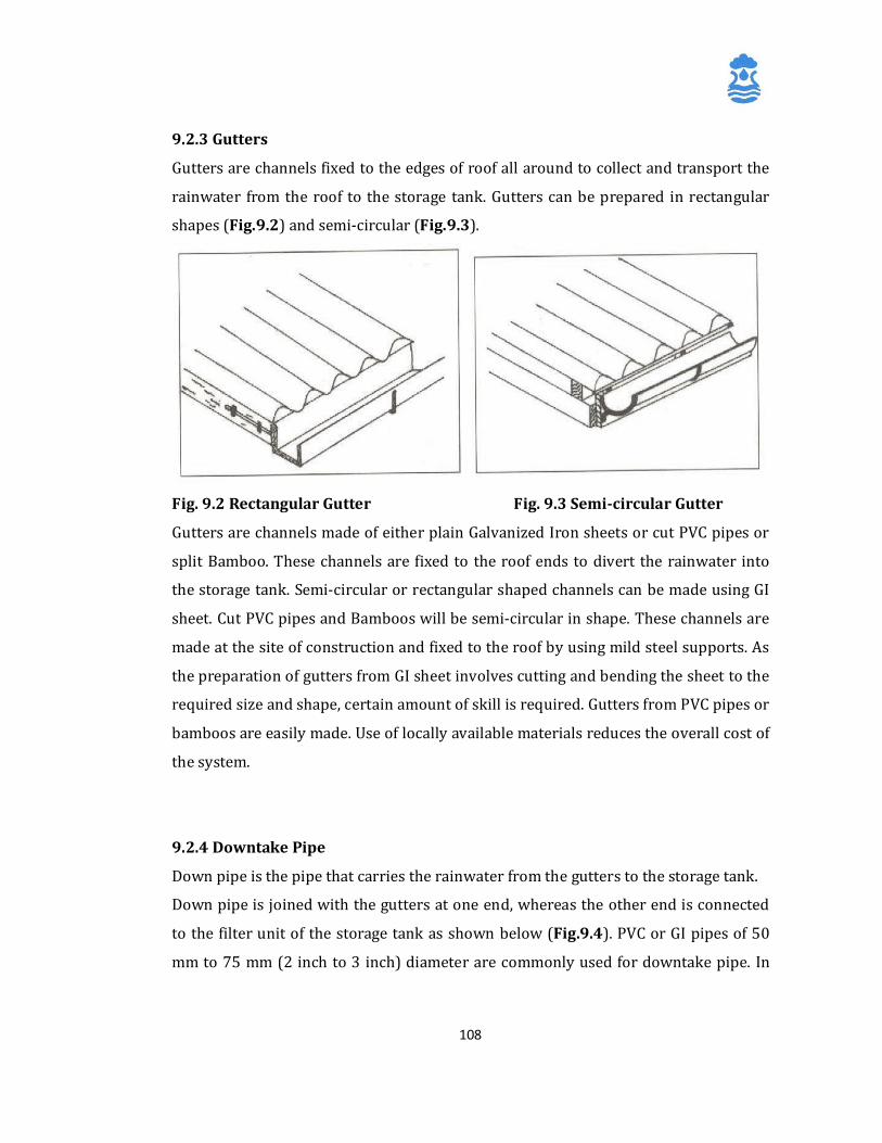
108
9.2.3 Gutters
Gutters are channels fixed to the edges of roof all around to collect and transport the
rainwater from the roof to the storage tank. Gutters can be prepared in rectangular
shapes (Fig.9.2) and semi-circular (Fig.9.3).
Fig. 9.2 Rectangular Gutter Fig. 9.3 Semi-circular Gutter
Gutters are channels made of either plain Galvanized Iron sheets or cut PVC pipes or
split Bamboo. These channels are fixed to the roof ends to divert the rainwater into
the storage tank. Semi-circular or rectangular shaped channels can be made using GI
sheet. Cut PVC pipes and Bamboos will be semi-circular in shape. These channels are
made at the site of construction and fixed to the roof by using mild steel supports. As
the preparation of gutters from GI sheet involves cutting and bending the sheet to the
required size and shape, certain amount of skill is required. Gutters from PVC pipes or
bamboos are easily made. Use of locally available materials reduces the overall cost of
the system.
9.2.4 Downtake Pipe
Down pipe is the pipe that carries the rainwater from the gutters to the storage tank.
Down pipe is joined with the gutters at one end, whereas the other end is connected
to the filter unit of the storage tank as shown below (Fig.9.4). PVC or GI pipes of 50
mm to 75 mm (2 inch to 3 inch) diameter are commonly used for downtake pipe. In
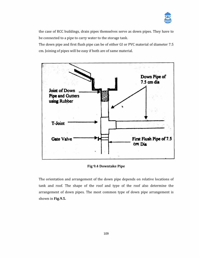
109
the case of RCC buildings, drain pipes themselves serve as down pipes. They have to
be connected to a pipe to carry water to the storage tank.
The down pipe and first flush pipe can be of either GI or PVC material of diameter 7.5
cm. Joining of pipes will be easy if both are of same material.
Fig 9.4 Downtake Pipe
The orientation and arrangement of the down pipe depends on relative locations of
tank and roof. The shape of the roof and type of the roof also determine the
arrangement of down pipes. The most common type of down pipe arrangement is
shown in Fig.9.5.
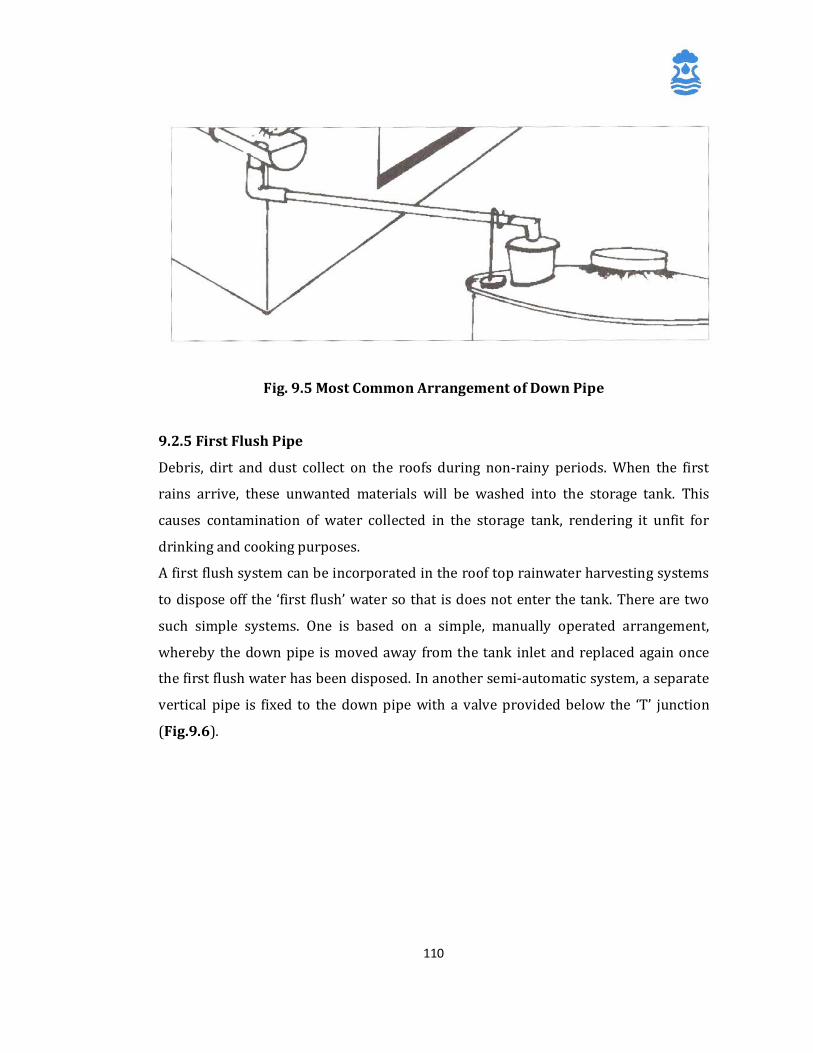
110
Fig. 9.5 Most Common Arrangement of Down Pipe
9.2.5 First Flush Pipe
Debris, dirt and dust collect on the roofs during non-rainy periods. When the first
rains arrive, these unwanted materials will be washed into the storage tank. This
causes contamination of water collected in the storage tank, rendering it unfit for
drinking and cooking purposes.
A first flush system can be incorporated in the roof top rainwater harvesting systems
to dispose off the ‘first flush’ water so that is does not enter the tank. There are two
such simple systems. One is based on a simple, manually operated arrangement,
whereby the down pipe is moved away from the tank inlet and replaced again once
the first flush water has been disposed. In another semi-automatic system, a separate
vertical pipe is fixed to the down pipe with a valve provided below the ‘T’ junction
(Fig.9.6).
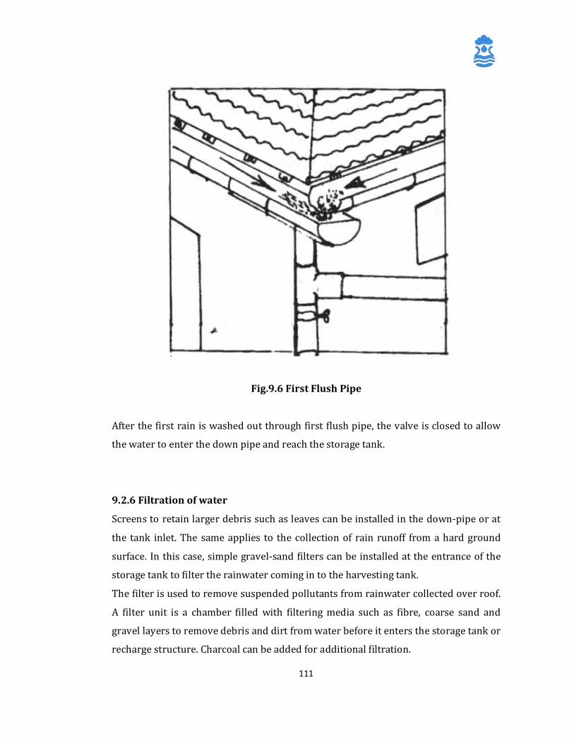
111
Fig.9.6 First Flush Pipe
After the first rain is washed out through first flush pipe, the valve is closed to allow
the water to enter the down pipe and reach the storage tank.
9.2.6 Filtration of water
Screens to retain larger debris such as leaves can be installed in the down-pipe or at
the tank inlet. The same applies to the collection of rain runoff from a hard ground
surface. In this case, simple gravel-sand filters can be installed at the entrance of the
storage tank to filter the rainwater coming in to the harvesting tank.
The filter is used to remove suspended pollutants from rainwater collected over roof.
A filter unit is a chamber filled with filtering media such as fibre, coarse sand and
gravel layers to remove debris and dirt from water before it enters the storage tank or
recharge structure. Charcoal can be added for additional filtration.
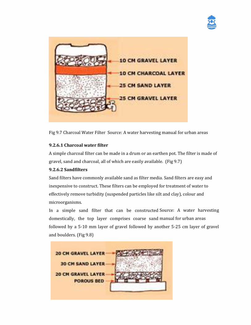
112
9.2.6.1 Charcoal water filter
A simple charcoal filter can be made in a drum or an earthen pot. The filter is made of
gravel, sand and charcoal, all of which are easily available. (Fig 9.7)
9.2.6.2 Sandfilters
Sand filters have commonly available sand as filter media. Sand filters are easy and
inexpensive to construct. These filters can be employed for treatment of water to
effectively remove turbidity (suspended particles like silt and clay), colour and
microorganisms.
In a simple sand filter that can be constructed
domestically, the top layer comprises coarse sand
followed by a 5-10 mm layer of gravel followed by another 5-25 cm layer of gravel
and boulders. (Fig 9.8)
Fig 9.7 Charcoal Water Filter Source: A water harvesting manual for urban areas
Source: A water harvesting
manual for urban areas
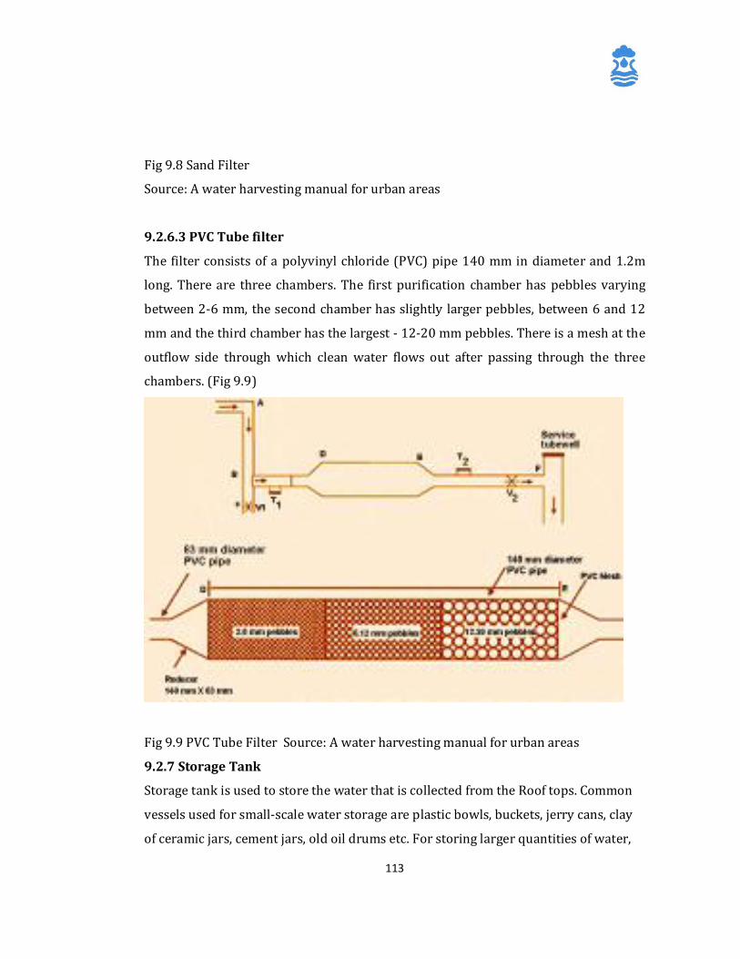
113
Fig 9.8 Sand Filter
Source: A water harvesting manual for urban areas
9.2.6.3 PVC Tube filter
The filter consists of a polyvinyl chloride (PVC) pipe 140 mm in diameter and 1.2m
long. There are three chambers. The first purification chamber has pebbles varying
between 2-6 mm, the second chamber has slightly larger pebbles, between 6 and 12
mm and the third chamber has the largest - 12-20 mm pebbles. There is a mesh at the
outflow side through which clean water flows out after passing through the three
chambers. (Fig 9.9)
Fig 9.9 PVC Tube Filter Source: A water harvesting manual for urban areas
9.2.7 Storage Tank
Storage tank is used to store the water that is collected from the Roof tops. Common
vessels used for small-scale water storage are plastic bowls, buckets, jerry cans, clay
of ceramic jars, cement jars, old oil drums etc. For storing larger quantities of water,
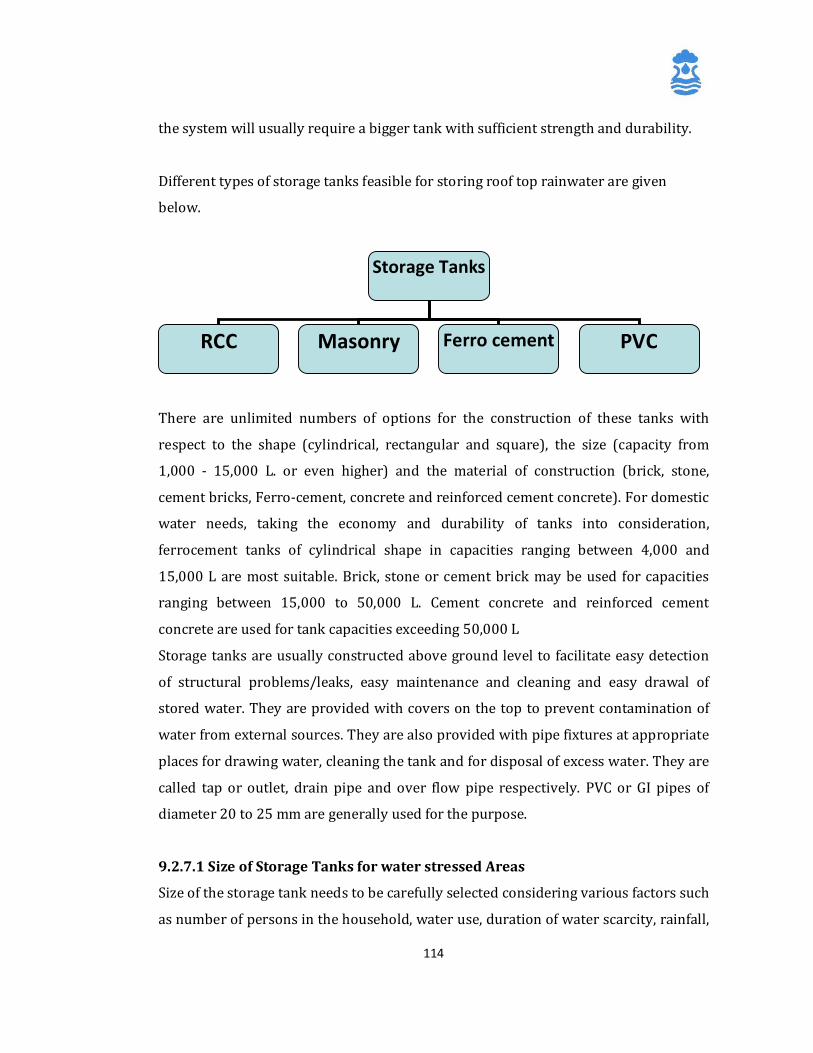
114
the system will usually require a bigger tank with sufficient strength and durability.
Different types of storage tanks feasible for storing roof top rainwater are given
below.
There are unlimited numbers of options for the construction of these tanks with
respect to the shape (cylindrical, rectangular and square), the size (capacity from
1,000 - 15,000 L. or even higher) and the material of construction (brick, stone,
cement bricks, Ferro-cement, concrete and reinforced cement concrete). For domestic
water needs, taking the economy and durability of tanks into consideration,
ferrocement tanks of cylindrical shape in capacities ranging between 4,000 and
15,000 L are most suitable. Brick, stone or cement brick may be used for capacities
ranging between 15,000 to 50,000 L. Cement concrete and reinforced cement
concrete are used for tank capacities exceeding 50,000 L
Storage tanks are usually constructed above ground level to facilitate easy detection
of structural problems/leaks, easy maintenance and cleaning and easy drawal of
stored water. They are provided with covers on the top to prevent contamination of
water from external sources. They are also provided with pipe fixtures at appropriate
places for drawing water, cleaning the tank and for disposal of excess water. They are
called tap or outlet, drain pipe and over flow pipe respectively. PVC or GI pipes of
diameter 20 to 25 mm are generally used for the purpose.
9.2.7.1 Size of Storage Tanks for water stressed Areas
Size of the storage tank needs to be carefully selected considering various factors such
as number of persons in the household, water use, duration of water scarcity, rainfall,
Storage Tanks
RCC Masonry Ferro cement PVC
115
type and size of house roof and the status of existing water sources in the area. In
general, the period of water scarcity for domestic purposes is found to be in the range
of 90 days to 200 days depending upon the quantity and distribution of rainfall and
water sources existing in the area.
The water use of the household should first be studied, considering the local culture
and habits of the people influencing the water use. Availability of water at the
doorstep, as is the case with RRHS, is likely to increase the water use of the
household. This results in increase in required size of storage tank and its cost. It is
found that the per capita water use varies over a range of 3 litres to 10 litres per day.
A per capita water consumption of 5 litres per day for the domestic drinking and
cooking purposes is found optimum. Adding 20% towards additional water
requirement for visitors, festivals and wastage, a per capita water requirement of 6
litres per day may be considered for selecting the size of water storage tank. The size
of water storage tank may be determined using the following relation and
approximating to the nearest thousand:
Size of Storage tank (in litres)
=
No. of persons in the household x
Period of water scarcity (in days) x
Per capita water requirement (in liters per day)
The capacity of storage tank, which reflects the total household water requirement
during the period of water scarcity, need to be checked with the amount of water
available from house rooftop during rains. If the amount of water available from roof
is less than the required capacity of storage tank, then the household shall use the
water available from roof only for a part of the water scarcity period.
Water available from roof is obtained from the following relation:
Water available (in litres) = Annual rainfall (in mm) x Roof area (in sq.m) x
Runoff Coefficient
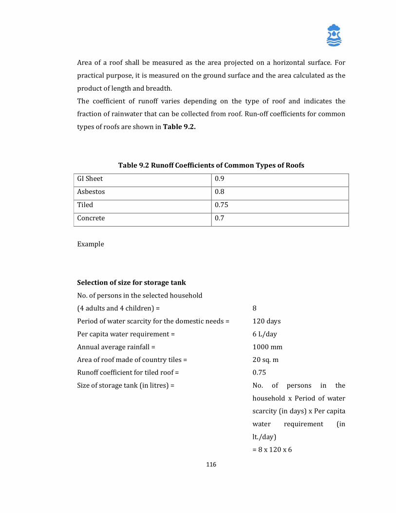
116
Area of a roof shall be measured as the area projected on a horizontal surface. For
practical purpose, it is measured on the ground surface and the area calculated as the
product of length and breadth.
The coefficient of runoff varies depending on the type of roof and indicates the
fraction of rainwater that can be collected from roof. Run-off coefficients for common
types of roofs are shown in Table 9.2.
Table 9.2 Runoff Coefficients of Common Types of Roofs
GI Sheet 0.9
Asbestos 0.8
Tiled 0.75
Concrete 0.7
Example
Selection of size for storage tank
No. of persons in the selected household
(4 adults and 4 children) = 8
Period of water scarcity for the domestic needs = 120 days
Per capita water requirement = 6 L/day
Annual average rainfall = 1000 mm
Area of roof made of country tiles = 20 sq. m
Runoff coefficient for tiled roof = 0.75
Size of storage tank (in litres) = No. of persons in the
household x Period of water
scarcity (in days) x Per capita
water requirement (in
lt./day)
= 8 x 120 x 6
117
= 5,760 L
Say 6,000 L
Check with water availability from roof top
Water available from roof top =
Annual rainfall (in mm) X Area of roof (in sq.m) X Coefficient of runoff for the roof
= 1000 X 20 X 0.75
= 15000 liters
9.2.7.2 Size of Storage Tank for areas having regular water supply
In areas having regular water supply throughout the year, the size of the storage tank
for harvesting roof top rainwater can be decided as per the quantum of rainfall
occurring in a single event. For this, it is assumed that serious water scarcity days are
not counted and collection of roof top rainwater is voluntary/mandatory as an effort
towards saving our natural resources. Moreover, it is difficult to create enough
storage space due to various constraints. In such a situation, it is ideal to create the
storage space to collect the rainfall per spell and utilize the same before the next spell.
In this case,
Water available from roof =
Annual rainfall (in mm) X Area of roof (in sq m) X Runoff coefficient for the roof
Water available per spell of rainfall =
Rainfall per spell X Area of roof (in sq m) X Runoff coefficient for the roof
9.2.8 Collection Sump
A small pit is normally dug in the ground beneath the tap of the storage tank and
constructed in brick masonry to make a chamber, so that a vessel could be
conveniently placed beneath the tap for collecting water form the storage tank. A
small hole is left at the bottom of the chamber, to allow the excess water to drain-out
without stagnation. Size of collection pit shall be 60 cm x 60 cm x 60 cm.
118
9.2.9 Pump Unit
A hand pump or a power pump fitted to the storage sump facilitates lifting of water to
the user. The size of the pump has to be decided depending upon the consumption of
the stored water.
9.3 Data Requirements for Planning Rainwater Harvesting Systems
9.3.1 Amount of Rainfall (mm/year): The total amount of water available is the
product of total available rainfall and the surface area from which it is collected. There
is usually a runoff coefficient included in the computation to account for evaporation
and other losses. Mean annual rainfall data may be used for obtaining rainfalls in an
average year.
9.3.2 Rainfall Distribution: Rainfall pattern as well as the total rainfall determines
the feasibility of a rainwater harvesting system in an area. A climate where rainfall is
received regularly throughout the year will mean that the storage requirement and
hence the system costs will be correspondingly low. On the other hand, in areas
whichreceive a major part of the annual rainfall during a couple of months, the water
collected during the rainy season has to be stored for as long as possible, requiring
huge storage tanks coupled with provision for treatment. In such cases, it may be
more economical to use rainwater to recharge ground water aquifers so that it can be
extracted at times of need. Long-term rainfall records are necessary to ascertain the
rainfall pattern.
9.3.3 Intensity of Rainfall: The maximum intensity of rainfall in mm/hr for a short
duration (normally 20 min) will decide the peak flow to be harvested by the roof top
rainwater harvesting system. The size of the gutter and diameter of down-take pipes
have to be estimated on the basis of the peak flow.
9.3.4 Surface Area: The scope of any roof top rainwater harvesting system is
restricted by the size of the roof forming the catchment. Other surfaces can also be
included to supplement the roof top catchment area wherever feasible. Accurate
estimate of total surface area of the catchment is a necessary prerequisite for
planning the scheme.
119
9.3.5 Storage Capacity: The storage tank is usually the most expensive component of
a rainwater harvesting system and hence, a careful analysis of storage requirements
against the cost has to be carried out prior to implementation of the scheme.
9.3.6 Daily Demand: This varies considerably from 10-15 litre per-capita per day
(lpcd) in some parts of the world to several hundred lpcd in some industrialized
countries. This will have obvious impacts on system specification.
9.3.7 Number of Users: This will greatly influence the requirements and design
specifications of the rainwater harvesting system.
9.3.8 Cost: Cost is a major factor in any rainwater-harvesting scheme.
9.3.9 Alternative Water Sources: Availability of alternative water sources can make
a significant difference to the usage pattern of the water collected using rainwater
harvesting systems. If a sustainable and safe ground water source is available within
economic distances, a rainwater harvesting system may provide a reliable supply of
water for a house/community for the majority of the year. On the other hand, where
rainwater is to be stored and used only for domestic use, the pattern of use will
depend on the quality of water.
9.3.10 Water management Strategy: A judicious water management strategy is
required for proper and optimum use of harvested water. In situations where there is
strong reliance on stored rainwater, there is need to control or manage the amount of
water being used so that it is available for a longer period.
9.4 Feasibility of Roof Top Rainwater Harvesting Systems in Rural Area
In rural area, ponds, streams and wells have traditionally been used as sources of
water for drinking and other domestic uses. In recent years, bore wells with hand
pumps and small water supply schemes have almost replaced these traditional
sources of water. Yet, in many rural habitations, these sources have not been able to
supply water to the rural households round the year, due to various reasons.
Domestic Roof top Rainwater Harvesting System (RRHS) provides a viable solution to
bridge the gap between demand and supply of water in such areas, especially during
periods of water scarcity. Specifically, RRHS is applicable in:
120
• Areas where traditional water sources like ponds, streams and wells dry up
during summer.
• Areas with problems of ground water salinity such as coastal areas.
• Areas where ground water has high concentration of harmful chemical
constituents such as fluoride, iron and arsenic.
• Areas where water sources are contaminated due to pollution from various
sources.
• The advantages of RRHS over conventional water supply systems in rural
areas are:
• It can provide a dependable, economical and durable source of water for
drinking and cooking purposes to the rural households, especially during
periods of water scarcity.
• Water is made available at the doorstep of the house.
• Easy access to the source of water improves the health and hygiene of family.
• Time spent in fetching water from distant water sources is considerably
reduced. This generally being the responsibility of women, the time saved
could be productively used for themselves and their family.
• Rainwater from roof top is free from contamination and pollution, and
generally found clean and potable.
• Requires simple maintenance, which could be carried out by the users easily.
• Construction and maintenance are simple and does not require sophisticated
tools or technology.
The planning of roof top rainwater harvesting systems in an area needs to be done in
terms of its technical suitability, social acceptance and economic viability.
9.5 Technical Suitability
Assessing technical suitability involves the study of factors which influence the need
and reliability of RRHS. Important considerations in this regard are described briefly
in the following sections.
121
9.5.1 Existing Water Sources
Existing water source such as community wells, hand pumps, small water supply
schemes, ponds and streams shall be studied. The availability of water, its quality and
accessibility of these sources during different seasons of the year should be looked
into for determining the period for which water may be required from RRHS.
9.5.2 Roof Catchment
The type of roof determines the quality of water that is collected in the storage tank.
Among the commonly seen roof types in rural areas, concrete, tiled, asbestos sheet
and galvanized iron sheet are most suitable as roof catchments. The roof should be
away from big trees to avoid accumulation of leaf litter and bird droppings. Thatched
roofs are not suitable as roof catchments because the water collected from these roofs
gets brownish colour and carries pieces of roof material.
The slope and shape of the roof are also important in planning a roof top rain top
rainwater harvesting system. Water flows with high velocity on steep-sloped roofs,
causing overflow or wastage of water form gutters and filter. Gentle slopes in the
range of 10 to 30 degrees are most suitable for smooth flow of water into the storage
tank. Roofs having slope more than 30 degrees are to be avoided wherever possible.
The size of roof is another important factor which determines the amount of water
available for storage in the RRHS. Generally, a roof area of 15-20 square meters is
required for collecting sufficient water required for a household. Roof catchments of
lesser sizes could become a limiting factor in designing RRHS to the required capacity.
9.5.3 Rainfall
Roof top rainwater harvesting systems collect rainwater from the roof catchments
during rainy days. Therefore, the amount and distribution of rainfall are major factors
influencing the dependability of such systems.
In India, a major part of the rainfall is received during monsoons. The southwest
monsoon reaches India in June and extends normally up to September. The northeast
monsoon extends from October to December. Kerala and north-eastern states benefit
from both the monsoons and hence receive rainfall extending over a period of 7-8
months. Rest of the country receives rains during southwest monsoon, except Tamil
Nadu, which receives comparatively more rains during northeast monsoon. The
122
rainfall is limited to 3-4 month in these regions. The average annual rainfall received
also varies across the country, from 200-250 mm in western Rajasthan to >3000 mm
in Kerala and north-eastern States.
The amount and period of rainfall at a given place are important factors that
determine the period for which water will be required from RRHS. For example, at
places where rainfall is received only during southwest monsoon (3-4 months), the
period of water requirement form RRHS could be longer than that of places in Kerala
and northeastern States. Also, in low rainfall areas such as western Rajasthan and
northern Gujarat, roof size could become a limiting factor as households in these
areas mayrequire water for an extended dry period of 7-8 months. Here, traditional
water harvesting systems make use of open lands, adjacent to the house, as
catchments areas for domestic water harvesting systems.
9.5.4 Space
Among all the components of roof top rainwater harvesting systems, storage tank is
the component occupying most space, and hence the space required for the system
depends on the size of the storage tank. For a typical 10,000 litre tank, the minimum
space required is 3.0 x 3.0m. Therefore, assessment of availability of space adjacent to
the house shall be done giving due importance to the preferences of the household.
Storage tanks located near the roof reduce the cost of down pipes. The site should be
clean, hygienic and away from cattle sheds to avoid contamination of stored water.
9.6 Social Acceptance
9.6.1 Acceptance of Roof Water as Drinking Water
Colour, odour and taste are the three important considerations for people in choosing
sources of drinking water. Clean water without any odour and with a ‘good taste’ is
usually preferred for dinking purpose. In case of water used for cooking, water having
lesser amounts of dissolved salts is preferred, because it consumes less time to boil
the food grains and vegetables. As the rainwater contains very little dissolved salts
and is almost free from pollutants, it tastes ‘good’ and is suitable for drinking and
cooking purposes.
123
However, in roof top rainwater harvesting systems, water is collected in the storage
tank during rainy season and is drawn from the system only after other sources like
ponds, wells and hand pumps dry up or become inaccessible to the household. This
means that the water collected in RRHS remains stored for a period of 3 to 6 months
before it is actually used. This makes water from RRHS not readily acceptable to many
people. Therefore, awareness and education programmes need to be organized on the
potability of water when the system is appropriately maintained. People’s
perceptions need to be given due importance during such programmes, to enable
them to develop appropriate understanding of the system.
Domestic water use varies from place to place depending on the culture and habits of
people as well as availability of water. Water made available at the doorstep is likely
to increase the water usage. Increased water use would improve the cleanliness and
hygiene within the household as well as improve the health of the people. Yet, people
have to be educated to draw water in controlled quantities so that they could benefit
from the system throughout the period of water scarcity to which the system is
designed.
9.6.2 Willingness of Households to Participate
Domestic Roof top Rainwater Harvesting Systems are meant for meeting the water
needs of individual households and are constructed right at their doorstep. Hence,
proper care and maintenance of the system by the household is essential for a reliable
supply of good quality water. Willingness of household to participate in planning,
construction and maintenance of
such systems are very important for the success of the programme. The motivating
factors such as availability of sufficient water, economy and ease in maintenance,
ownership of the system etc., which encourages the people to participate should be
identified and proper orientation should be given.
9.6.3 Traditional Practices of Roof Water Collection
Collection of roof water on small scale from house roofs to meet the immediate
household needs is a traditional practice in some parts of India such as north-eastern
124
states, Rajasthan and eastern coastal areas of Tamil Nadu. Small vessels or drums are
used to collect and store water. Locally available bamboo is split and used as gutters.
Existence of such practices makes RRHS to meet long-term needs acceptable.
However, training and transfer of knowledge on systematic and economical
construction of these systems is required.
9.7 Water Quality and Health
Rainwater is often used for drinking and cooking and hence it is vital that the highest
possible quality standards are maintained. Rainwater, unfortunately, often does not
meet the World Health Organization (WHO) water quality guidelines. This does not
mean that the water is unsafe to drink. It has been found that a favourable user
perception of rainwater quality (not necessarily perfect water quality) makes an
enormous difference to the acceptance of RWH as a water supply option. Generally,
the chemical quality of rainwater will fall within the WHO guidelines and rarely
presents problems. There are two main issues when looking at the quality and health
aspects of domestic rainwater harvesting systems.
9.7.1 Bacteriological Water Quality
Rainwater can become contaminated by faeces entering the tank from the catchment
area. It is advised that the catchment surface always be kept clean. Rainwater tanks
should be designed to protect the water from contamination by leaves, dust, insects,
vermin and other industrial or agricultural pollutants. Tanks should be located away
from trees, with good-fitting lids and kept in good condition. Incoming water should
be filtered or screened, or allowed to settle to take out foreign matter. Water, which is
relatively clean, on entry to the tank, will usually improve in quality if allowed to be
inside the tank for some time. Bacteria entering the tank will die off rapidly if the
water is relatively clean. Algae will grow inside a tank if sufficient sunlight is available
for photosynthesis. Keeping a tank dark and in a shady spot will prevent algae growth
and also keep the water cool. As already mentioned, there are a number of ways of
diverting the dirty ‘first flush’ water away from the storage tank. The area
surrounding a RWH structure should be kept in good sanitary condition, fenced off to
125
prevent animals fouling the area or children playing around the tank. Any pools of
water gathering around the tank should be drained and filled.
9.7.2 Insect Vectors
There is a need to prevent insect vectors from breeding inside the tank. In areas
where malaria is prevalent, providing water tanks without any care for preventing
insect breeding can cause more problems than it solves. All tanks should be sealed to
prevent insects from entering. Mosquito-proof screens should be fitted to all
openings.
9.7.3 Water Treatment
There are several simple methods of treatment for water to made suitable for
drinking
� Boiling water will kill any harmful bacteria which may be present
� Adding chlorine in the right quantity (35ml of sodium hypochlorite per 1000
litres of water) will disinfect the water
� Slow sand filtration will remove any harmful organisms.
� A recently developed technique called SODIS (Solar Disinfections) utilises plastic
bottles, which are filled with water and placed in the sun for one full day. The back of
the bottle is painted black.
The reasons for variations in chemical constituents and bacteriological properties of
water from RRHS could be many, the most important ones of which are listed below:
� Even though the water flows over the house roof for a short distance, it may
dissolve some chemicals deposited on the roof or the residues of chemical reactions
between the atmospheric gases and the roof material.
� In general, rainwater is pure and free from contamination. However, the air
pollution from factories, industries, mining etc. does influence the chemical quality of
water vapour in the atmosphere. When this water vapour condenses and comes in
contact with the roof material, it may react and leave residue on the roof.
This phenomenon usually occurs over areas surrounding industries. The impact of
this pollution on the rainwater quality is not alarming, but needs attention.
� Rainwater, while passing on the roof may carry the dust and debris resulting in
change in the quality of water.
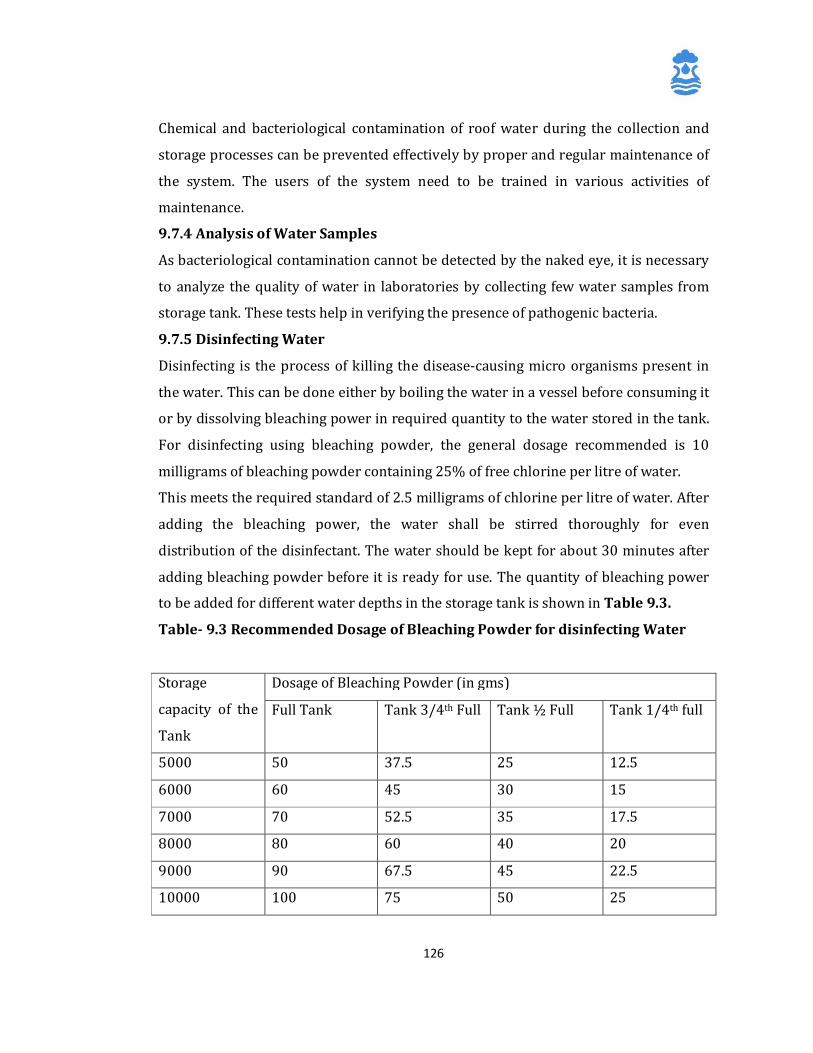
126
Chemical and bacteriological contamination of roof water during the collection and
storage processes can be prevented effectively by proper and regular maintenance of
the system. The users of the system need to be trained in various activities of
maintenance.
9.7.4 Analysis of Water Samples
As bacteriological contamination cannot be detected by the naked eye, it is necessary
to analyze the quality of water in laboratories by collecting few water samples from
storage tank. These tests help in verifying the presence of pathogenic bacteria.
9.7.5 Disinfecting Water
Disinfecting is the process of killing the disease-causing micro organisms present in
the water. This can be done either by boiling the water in a vessel before consuming it
or by dissolving bleaching power in required quantity to the water stored in the tank.
For disinfecting using bleaching powder, the general dosage recommended is 10
milligrams of bleaching powder containing 25% of free chlorine per litre of water.
This meets the required standard of 2.5 milligrams of chlorine per litre of water. After
adding the bleaching power, the water shall be stirred thoroughly for even
distribution of the disinfectant. The water should be kept for about 30 minutes after
adding bleaching powder before it is ready for use. The quantity of bleaching power
to be added for different water depths in the storage tank is shown in Table 9.3.
Table- 9.3 Recommended Dosage of Bleaching Powder for disinfecting Water
Storage
capacity of the
Tank
Dosage of Bleaching Powder (in gms)
Full Tank Tank 3/4th Full Tank ½ Full Tank 1/4th full
5000 50 37.5 25 12.5
6000 60 45 30 15
7000 70 52.5 35 17.5
8000 80 60 40 20
9000 90 67.5 45 22.5
10000 100 75 50 25
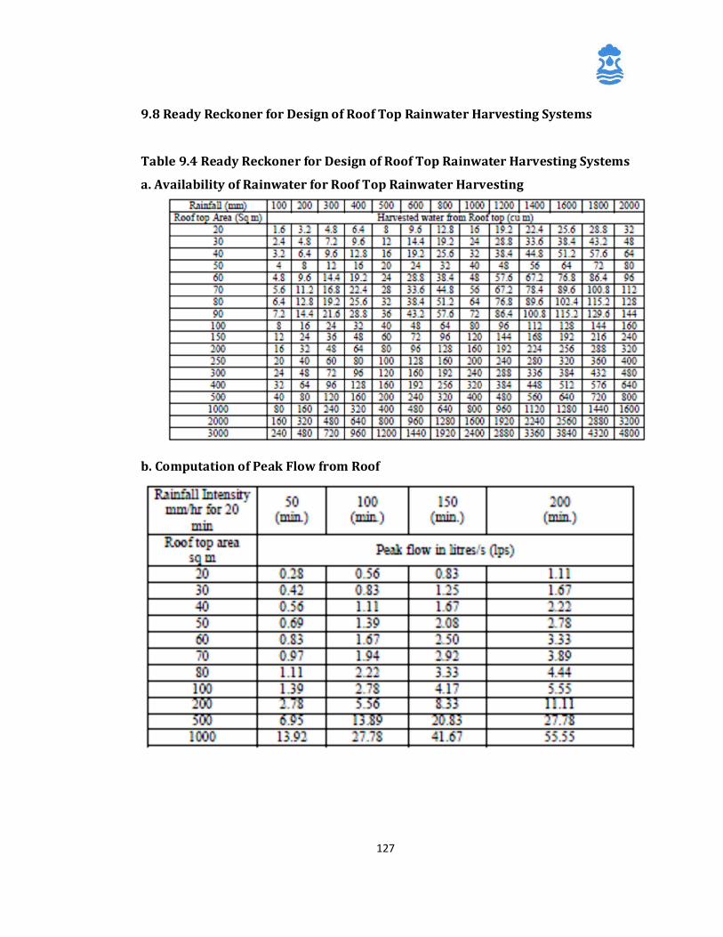
127
9.8 Ready Reckoner for Design of Roof Top Rainwater Harvesting Systems
Table 9.4 Ready Reckoner for Design of Roof Top Rainwater Harvesting Systems
a. Availability of Rainwater for Roof Top Rainwater Harvesting
b. Computation of Peak Flow from Roof
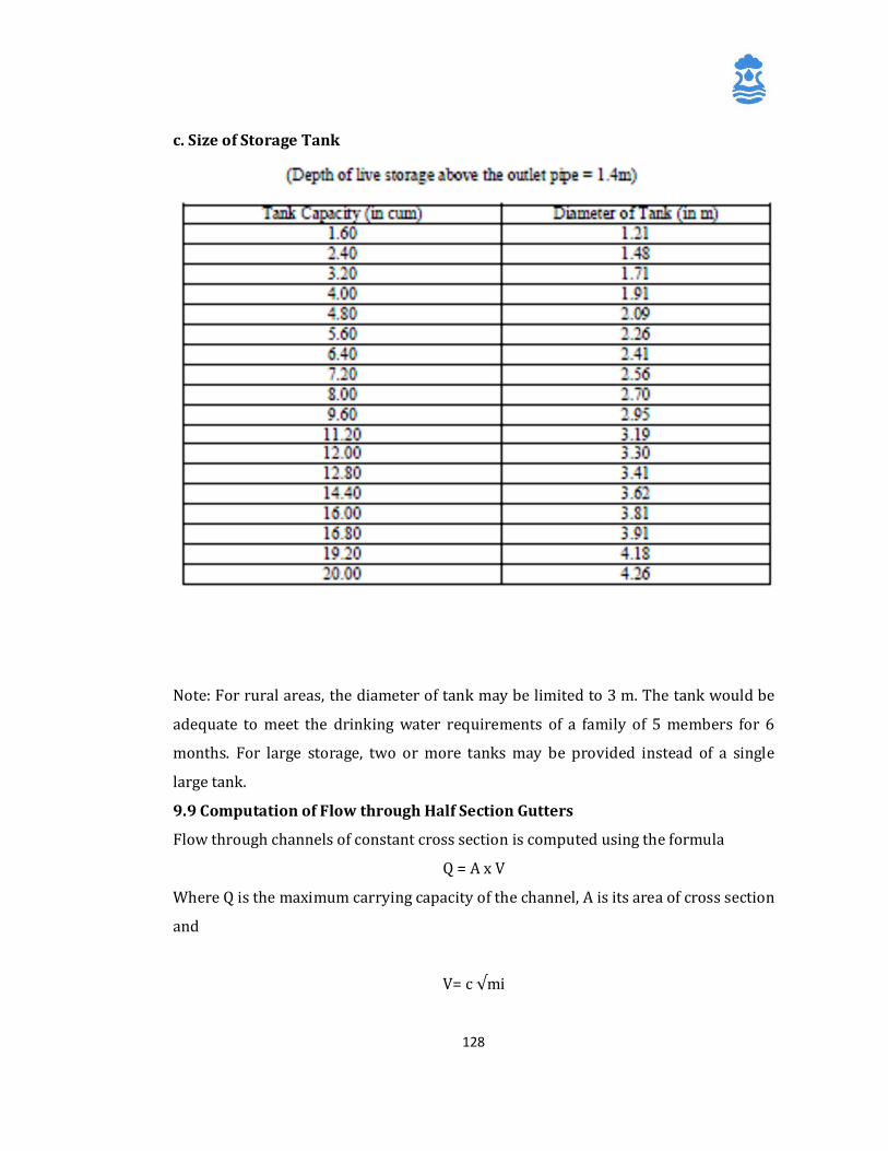
128
c. Size of Storage Tank
Note: For rural areas, the diameter of tank may be limited to 3 m. The tank would be
adequate to meet the drinking water requirements of a family of 5 members for 6
months. For large storage, two or more tanks may be provided instead of a single
large tank.
9.9 Computation of Flow through Half Section Gutters
Flow through channels of constant cross section is computed using the formula
Q = A x V
Where Q is the maximum carrying capacity of the channel, A is its area of cross section
and
V= c √mi
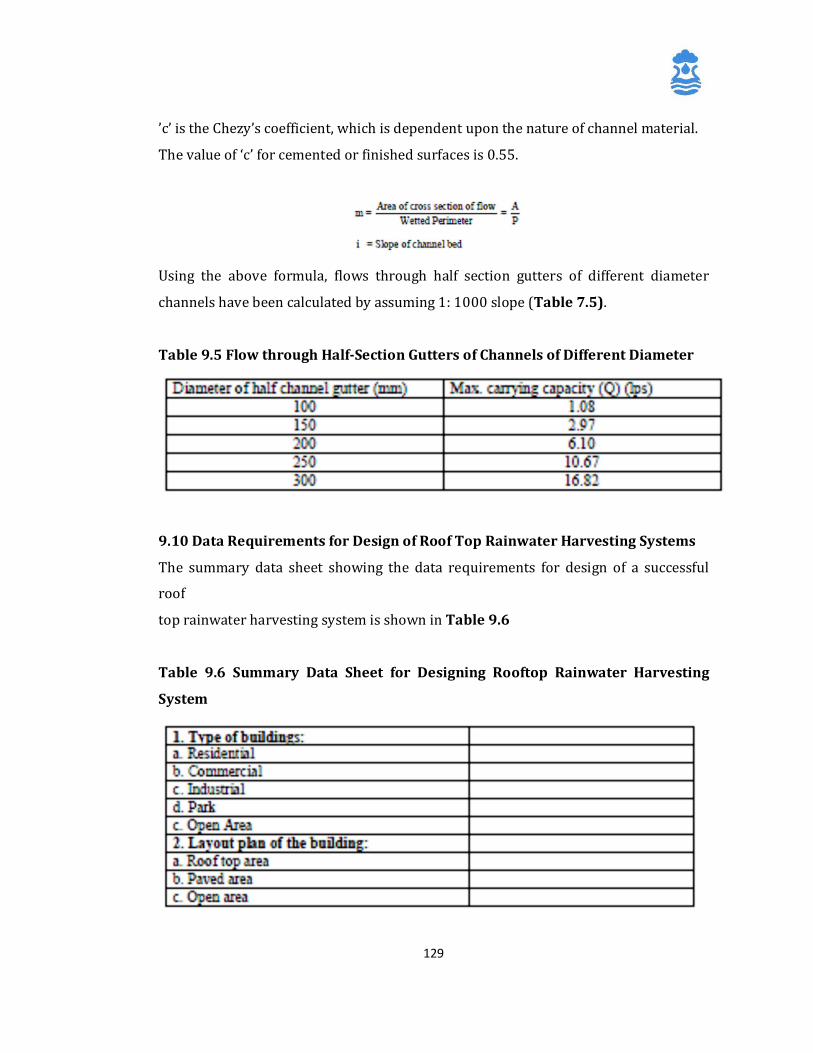
129
’c’ is the Chezy’s coefficient, which is dependent upon the nature of channel material.
The value of ‘c’ for cemented or finished surfaces is 0.55.
Using the above formula, flows through half section gutters of different diameter
channels have been calculated by assuming 1: 1000 slope (Table 7.5).
Table 9.5 Flow through Half-Section Gutters of Channels of Different Diameter
9.10 Data Requirements for Design of Roof Top Rainwater Harvesting Systems
The summary data sheet showing the data requirements for design of a successful
roof
top rainwater harvesting system is shown in Table 9.6
Table 9.6 Summary Data Sheet for Designing Rooftop Rainwater Harvesting
System
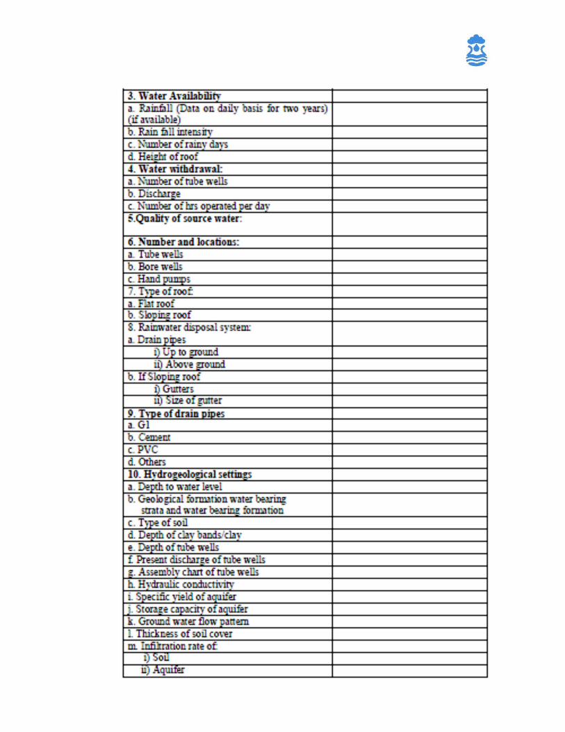
130

131
9.11 Design Example
A house has a sloping roof of G.I.sheet with an area of 50 sq m. The owner of the house
has a family of 5 members. Design a roof water harvesting system. The 10 year rainfall
for the areas is as follows:
The maximum rainfall intensity is 10 mm/hour. The lower edge of the roof is 3 m
above the ground.
Solution:
Arranging the rainfall in descending order, we get: 380, 355,340, 335, 330, 320, 311,
290, 280
The highest rainfall of 380 mm is equalled or exceeded only once in 10 years.
Therefore, it’s expected that the return period of this much rainfall is 1 in 10 years,
which is ‘rare’. On the other hand, the lowest rainfall of 280 mm is equalled or
exceeded in all the 10 years. Thus, this is the most reliable figure. So, the system may
be designed for this rainfall.
From Table 9.4a, for the roof area of 50 sq m and rainfall of 280 mm, the available
water works out as 11.2 cum or 11,200 litres Allowing for a consumption of 10 lpcd,
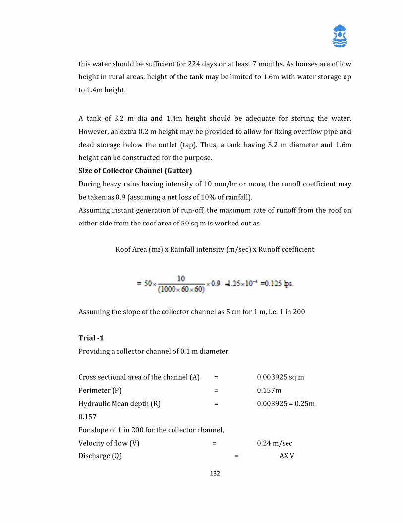
132
this water should be sufficient for 224 days or at least 7 months. As houses are of low
height in rural areas, height of the tank may be limited to 1.6m with water storage up
to 1.4m height. A tank of 3.2 m dia and 1.4m height should be adequate for storing the water.
However, an extra 0.2 m height may be provided to allow for fixing overflow pipe and
dead storage below the outlet (tap). Thus, a tank having 3.2 m diameter and 1.6m
height can be constructed for the purpose.
Size of Collector Channel (Gutter)
During heavy rains having intensity of 10 mm/hr or more, the runoff coefficient may
be taken as 0.9 (assuming a net loss of 10% of rainfall).
Assuming instant generation of run-off, the maximum rate of runoff from the roof on
either side from the roof area of 50 sq m is worked out as
Roof Area (m2) x Rainfall intensity (m/sec) x Runoff coefficient
Assuming the slope of the collector channel as 5 cm for 1 m, i.e. 1 in 200
Trial -1
Providing a collector channel of 0.1 m diameter
Cross sectional area of the channel (A) = 0.003925 sq m
Perimeter (P) = 0.157m
Hydraulic Mean depth (R) = 0.003925 = 0.25m
0.157
For slope of 1 in 200 for the collector channel,
Velocity of flow (V) = 0.24 m/sec
Discharge (Q) = AX V
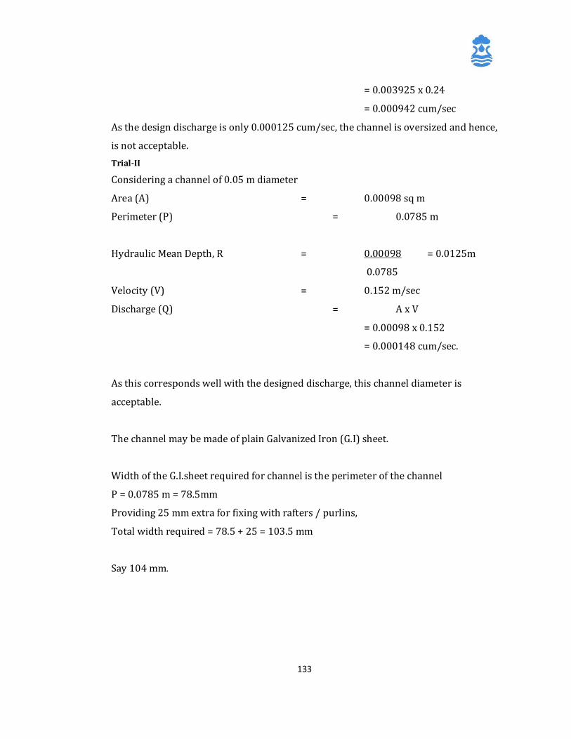
133
= 0.003925 x 0.24
= 0.000942 cum/sec As the design discharge is only 0.000125 cum/sec, the channel is oversized and hence,
is not acceptable. Trial-II
Considering a channel of 0.05 m diameter
Area (A) = 0.00098 sq m
Perimeter (P) = 0.0785 m
Hydraulic Mean Depth, R = 0.00098 = 0.0125m
0.0785
Velocity (V) = 0.152 m/sec
Discharge (Q) = A x V
= 0.00098 x 0.152
= 0.000148 cum/sec.
As this corresponds well with the designed discharge, this channel diameter is
acceptable.
The channel may be made of plain Galvanized Iron (G.I) sheet.
Width of the G.I.sheet required for channel is the perimeter of the channel
P = 0.0785 m = 78.5mm
Providing 25 mm extra for fixing with rafters / purlins,
Total width required = 78.5 + 25 = 103.5 mm
Say 104 mm.
134
10 Impact Assessment Sustainability structures are constructed mostly with the objective of augmenting
drinking water resources and/or to improve its quality. Assessment of impacts of the
sustainability schemes implemented is essential to assess the efficacy of structures
constructed and helps in identification of cost effective mechanisms for optimal
improvements in the sustainability of the Drinking Water sources. It also helps to
make necessary modifications in site selection, design and construction of structures
in future.
Impact assessment may require monitoring of the sustainability structures, ground
water regime, changes in pattern of water supply, cropping pattern, crop productivity
and/or water quality. In case of Recharge structures, tracers such as Tritium,
Rhodomine B, fluorescent dyes and environmental isotopes are also being used for
demarcating the area benefited.
The methodology of impact assessment is highly site-specific and can vary
considerably depending upon various factors such as hydrogeological set-up and
ground water utilization pattern. General guidelines for impact assessment of
sustainability structures are discussed briefly in the following sections.
10.1 Monitoring of Recharge Structures
Surface structures such as percolation ponds, check dams and cement plugs need to
be monitored at regular intervals to assess the actual storage created in the
structures, period of impounding, capacity utilization of the structure, rate of
percolation and siltation problems if any. Quantification of storage in the structures
may require setting up of monitoring devices within the structures. Devices such as
gauges for area-capacity analysis are commonly used in surface recharge structures.
Daily monitoring records are preferred for realistic assessment of storage created by
multiple fillings of the structures. Evaporation and seepage losses from the structures
are also to be accounted properly to evaluate the recharge efficiency of the structures.
In case of subsurface structures, the intake water supplied to the structures is
measured by suitable measuring devices. Appropriate measuring devices such as flow
135
meters and ‘V’ notches can be used for measurement. Daily records of such
measurements help quantify the amount of water utilized for recharge purpose.
10.2 Water Level Monitoring
The objective of water level monitoring is to study the effect of artificial recharge on
the natural ground water system. The monitoring system should be designed
judiciously to monitor impact of individual structures which can further be extended
to monitor the impact of groups of such structures in the area where artificial
recharge is being done. Monitoring of water levels during the planning stage of
artificial recharge projects helps in assessment of the ground water conditions of the
area and helps in identification of the most suitable method for ground water
augmentation. A properly designed observation well network is used for
understanding the ground water flow pattern and the spatial and temporal changes in
water levels/ potentiometric heads in the area.
During the planning and feasibility study stage, the observation well network is
generally of low well density but spread over a large area with the primary aim of
defining the boundaries of the aquifer to be recharged and to know the hydraulic
characteristics of the natural ground water system. After identification of the feasible
artificial recharge structures, the observation well network is redefined in a smaller
area with greater well density.
For effective monitoring of the changes in the water levels due to artificial recharge,
the network should have observation wells near the centre of the recharge facility, at
a sufficient distance from the recharge facility to observe composite effects and also
near the limits of hydrological boundaries. If the aquifer being recharged is overlain
by confining /semi-confining layers, piezometers should be installed to monitor the
water levels of overlying and underlying aquifers separately to study the effects in
both the aquifers. In cases where surface water bodies are hydraulically connected
with the aquifers being recharged, it is advisable to monitor the water level profiles of
both surface water and ground water.
136
Demarcation of the zone of influence of the artificial recharge structure is one of the
main objectives monitoring in the context of artificial recharge projects. The following
observations are generally associated with the area benefited by an artificial recharge
structure:
1. Well hydrographs in the area benefited will have a flat apex during the period when
there is water in the recharge structure (tank, pit etc.).
2. Wells located outside the zone of influence normally show an angular apex during
the period of recharge, whereas those situated within the zone of influence have a
flatter apex.
3. The recession limbs of well hydrographs close to a recharge structure normally
have gentle gradients as compared to those located far off.
4. Crops in the zone of influence are normally healthier when compared to those
outside the benefited area. Furthermore, crops with high water requirements are
more likely to be grown in the zone of influence.
5. Well yields in the zone of influence will normally be higher when compared to those
outside it. Wells in benefited zone may have more sustainability in lean period than
those located outside.
The behaviour of water table / piezometric head profile prepared from the data
collected from the observation well network over a period of time can clearly
establish the efficacy of the artificial recharge scheme. Answers to questions related
to the extent of the area benefited and the quantification of ground water
augmentation could also be worked out from such data. The study of fluctuation over
time for both surface and ground water levels in the same area may also indicate
whether the ground water augmentation is taking place as envisaged or not. In case
any deviation is observed, the reasons for the same could be identified and necessary
remedial measures taken up.
10.3 Water Quality Monitoring
A proper evaluation of potential water quality and aquifer quality problems
associated with artificial recharge is a key component of a ground water recharge
137
scheme. The development of reliable pre-, operational and post-operational
monitoring programs is an integral part of the development of a successful ground
water recharge scheme. A reliable water quality monitoring system for an artificial
recharge scheme will involve i) Evaluation of existing water quality data, ii) pre-
operational monitoring, iii) operational monitoring and iv) post-operational
monitoring.
10.3.1 Evaluation of Existing Water Quality Data
The first step that should be followed in evaluating the potential water quality
problems associated with a proposed ground water recharge project is to obtain
detailed information on the chemical characteristics of the proposed recharge waters.
A critical examination of the existing data on the waters that would be recharged to
the aquifer should be made to first determine their reliability and representativeness.
In case the available data is not considered to be reliable, collection and analysis of
source water samples may be done afresh.
10.3.2 Pre-operational Monitoring
The augmentation of recharge by surface waters and their associated contaminants
can greatly increase the potential for ground water quality problems due to the
increased hydraulic and contaminant loading. The characterization of ground water
quality is often not adequately done to properly evaluate potential ground water and
aquifer quality problems associated with a ground water recharge project. it is
important to properly assess how the variable parameters in sampling such as bore
hole volume purged and rate of purging before sampling influences the composition
of the samples. Chemical parameters of particular importance in reliably assessing
ground water quality samples are the redox conditions within the aquifer and the
presence of suspended solids in the samples. Because of the chemistry of ferrous and
ferric iron, small changes in the redox (oxidation reduction) characteristics of the
sample as a result of the introduction of oxygen into the sample during sampling can
drastically change the chemical characteristics of the samples. Hence, it is important
to maintain the oxygen concentrations in a sample collected from an aquifer the same
as that of the aquifer. Failure to do so could readily change the distribution between
138
dissolved and particulate forms of many trace contaminants of water quality concern.
The presence of suspended solids in a water sample from an aquifer is a clear
indication that the sampling well has been improperly constructed and developed and
/or the sampling procedure used, especially the purging, has been improperly done.
Aquifers typically do not contain large amounts of suspended material. Aquifer
samples that contain suspended material are unreliable to properly characterize
chemical characteristics of the ground waters within the aquifer at the point and time
of sampling.
It is also important that the sampling program for the ground water is properly
developed to reflect the site specific hydrogeology of various principal components of
the aquifer. Failure to do so could readily lead to erroneous conclusions concerning
the chemical characteristics of the aquifer waters and the chemical reactions that can
take place within the aquifer upon introduction of recharge waters to it. Depending on
the situation, at least one year and often several years of data may be needed to
reliably characterize the aquatic system of interest. The best way to determine the
length of time necessary in pre-operational monitoring as well as the frequency of
monitoring a particular system is to examine the ability to predict the chemical
characteristics of the system prior to collecting the next set of samples. Once it
becomes clear that the characteristics of a particular recharge water source and
aquifer are predictable with a high degree of certainty based on past monitoring
results, it should then be possible to reduce the frequency and duration of pre-
operational monitoring. If, however, it is not possible to make these predictions
reliably because of the high variability in the systems, proceeding with the operation
of the proposed recharge project could be met with significant problems in detecting
incipient water quality problems before they adversely impact large parts of the
aquifer.
10.3.3 Operational Monitoring
With the initiation of the recharge activities, a significant increase in the frequency of
sampling, especially near the point of recharge, should occur. Actually the operational
sampling program should be initiated several months before actual recharge starts in
order to evaluate the ability to conduct the monitoring program with the facilities and
139
personnel available. If the pre-operational monitoring program has been passive, then
it should, at the time of initiation of recharge, become an active program, where the
data is examined in detail as soon as it is available for the purpose of determining its
reliability and any potential problems that are developing with the recharge project.
In addition to chemical and microbiological measurements in the recharge waters as
well as within the aquifer, detailed monitoring of the hydraulic characteristics of the
injection / infiltration system should be conducted to determine the changes in the
hydraulic characteristics of the recharge system and the aquifer in the vicinity of the
recharge. In addition to monitoring the chemical contaminants in the recharge waters
as well as aquifer, consideration should be given to the contaminant transformation
products that might be formed in the recharge water. An area of particular concern in
the recharge waters is whether there is sufficient BOD in these waters to exhaust the
dissolved oxygen in the aquifer waters for those aquifer systems that are oxic prior to
initiation of recharge. Bore hole dissolved oxygen measurements should be made at
frequent intervals at various distances from the point of recharge in order to detect
incipient dissolved oxygen depletion that could lead to its exhaustion from the
recharge waters. Since, in general, except for nitrate-related issues, anoxic conditions
in aquifers tend to lead to poor water quality, care should be taken to prevent the
recharge waters from becoming anoxic within the aquifer. Failure to do so could
readily result in iron, manganese and hydrogen sulphide problems. If problems of this
type start to develop, it may be necessary to add dissolved oxygen either directly or
through the introduction of hydrogen peroxide, in the recharge waters in order to
prevent problems of this type from occurring.
Once the operational monitoring program data have become stabilized, i.e. are
predictable based on past monitoring results, then the frequency of operational and
post-operational monitoring can be decreased. This will likely take several years of
operation, however, for fairly constant composition recharge waters and fairly
homogeneous aquifer system with respect to its hydrogeologic and chemical
characteristics.
140
The type of water quality monitoring programme depends on the specific problem
being studied, such as changes in ground water quality, effect of soil salination,
prevention of any contamination etc.
The samples to be collected will also depend on the purpose and are generally
categorized into a) Indicative, b) Basic and c) Comprehensive.
Indicative samples are collected at 1 to 4 months intervals and are used to ascertain
the presence of recharged water in the aquifer. Basic samples are taken at monthly
intervals for wells already influenced by recharge to determine the effect of recharge
on ground water quality and the purification provided by flow through the soil and
aquifer system. Comprehensive samples are taken at intervals of 6 months to 1 year
for observation wells and production wells to determine water quality with respect to
specific standards for intended water use.
10.3.4 Post-operational Monitoring
When groundwater recharge is terminated, it is important that the monitoring of the
aquifer be continued until the waters in the aquifer stabilize in composition. This will
normally take several years of monthly monitoring. This monitoring should continue
for quarterly intervals for several years.
141
11 Sustainability measures based on New and
Renewable energy
The groundwater abstraction mechanism plays a vital role in source
sustainability for groundwater based sources. It has been observed that sources
go unsustainable due to lowering of water levels or the non availability of
electricity to operate the pumps for groundwater abstraction. This issue can be
addressed by adapting the technique of solar dual pump based water supply.
This technique has been successfully demonstrated at various villages in
Maharashtra by Groundwater Survey and Development Agency. The technique
involves installation of a submersible power pump along with the Hand pump
assembly. This submersible power pump runs on solar energy, while the hand
pump installed at the tubewell also functions at the same time. Thus the
groundwater can be extracted even when the water table goes down below the
pumping capacity of ordinary Hand pump, and even when electricity is not
available, thus enhancing the sustainability of the source.
Similar measures are suggested and encouraged to be taken up under
sustainability component using the wind energy for groundwater abstraction,
after a proper feasibility survey for such schemes.
142
Annexure-1 Case Studies
Case Study - 1:
Name of the Project: Artificial Recharge to Ground Water through Check Dam
cum Ground Water Dam
Location: Naker Khad, Renta Dhawala, Tehsil Dehra, District Kangra (H.P)
The catchments of the Naker Khad at village Kundlihar is around 140 sq.km. Due to
structural disturbances a depression has been formed in which fluvial deposits have
been deposited in an area of around 4 sq.kms. This area known as Kundlihar is about
4 sq.km, has a high groundwater potential and around 2 mcm of water is being
pumped annually for water supply to Jwalamukhi town and adjoining areas from
here. It has been observed that over the last 10 to 15 years the yield of the wells has
decreased considerably during the summers, affecting the water supply to the holy
town of Jwalamukhi.
Observations made to design the scheme:
Desaturated Zone: The water level fluctuation during the pre-monsoon season
ranges from 5 to 6 meters, thus leaving about 5 meters of desaturated zones during
summer which is highly potential for storing the water for sustainable yield of the
existing 12 percolation wells.
Source of water: Only source of water is from the stream Naker Khad, which flows
for almost entire year, but during summer the base flow become negligible.
Lithology and Bedrock: The active flood plain area of Naker Khad (1.5 sq.km.)
underlain by pebbles and sands is highly permeable and most suitable for recharge.
Availability of water for recharge: In the period from October onwards there is
considerable base flow in the stream, which can be harnessed to recharge the
dried/desaturated zones of the flood plain of Naker Khad.
143
Salient features :
1. Site : Renta Dhawala
2. Co-ordinates : N 31° 51’ 40” – E 76° 16’ 00”
3. Stream : Naker Khad
4. Catchment area : 140 sq.km
5. Average annual rainfall : 1272 mm
6. Total runoff available at site : 120 mcm
7. Rock formation : Alluvium and sandstones
8. Structure : Check dam cum ground water dam
9. Volume of impounded water : 0.5 mcm
10. Total storage due to
repetitive fillings
: 2.625 mcm
11. Anticipitated recharge to
ground water
: 2.10 mcm
12. Cost of scheme : Rs. 24.14 lakhs
13. Life of scheme : 20 years
14. Cost per cubic meter of water : 5 paisa
Aims and objectives of the scheme:
1. Construction of recharge/conservation structure to augment the ground water
recharge throughout the year through surplus flow available in the Naker Khad
stream.
2. To restrict the desaturation of aquifer during the summer thereby giving
sustainability to the existing water supply.
3. To monitor the impact of additional ground water recharge on ground water regime.
4. To evaluate the cost benefit of artificial recharge techniques.
5. To train the State Government personnel in designing, implementing and operating
the artificial recharge schemes.
6. To create awareness among the farmers and local population about protecting and
proper management of ground water resources.
144
Hydrogeology Areal extent of alluvium : 4 sq.km. Thickness of alluvium : 15-20 m Thickness of saturated alluvium : 5-10 m Thickness of saturated alluvium during summer : 1-5 m Bed rock : sandstone Aquifer : sand, gravel, pebble Depth to ground water River bed : surface to 2 m bgl Adjoining area : 5-10 mbgl Ground water flow direction : south east Average yield of percolation wells : 8 lps Ground water quality : fresh Recharge and Monitoring Structures
Check Dam cum Ground Water Dam : 1 Piezometers : 6 Depth of piezometer : 15 m bgl Length of casing pipe : 13 m Length of filter pipe : 2 m Life of the structure : 20 years Cost Check Dam cum Ground Water Dam (1 no.) : Rs. 22,11,200 Piezometer (6 no.) : Rs. 2,02,500 Total : Rs.24,13,700 Cost per cubic meter of water recharged : Rs.0.05 Benefits of the Scheme:
Ø Arresting of ground water out flow
Ø Proper utilization of storm water
Ø Rise in water level by 2.5 m
Ø Sustainability of wells and springs
Ø Reviving dried up wells for assured irrigation and water supply
Ø Conservation of energy during pumping
Ø Reducing flood hazards and soil erosion
Ø Reclaiming 45 hectares of waste land into cultivable land
145
Ø Employment generation through improved ecology and environment
Impact of the scheme :
Ø Rise in water level by 2.5 m
Ø Saving of energy during pumping
Ø Reclamation of wasteland
Ø Generation of employment like fisheries
Case Study - 2: Demonstrative Project on Artificial Recharge to Ground Water
taken up during 2009-12
1. Karuvatar Watershed, Namakkal District, Tamil Nadu
Name of State: Tamil Nadu
Name of District: Namakkal
Name of Watershed: Karuvatar
Blocks benefited: Namakkal, Mohanur, Erumapetty
Total Target
Total number of Structures Proposed: 52
Total numbers of Check Dams: 10
Total numbers of Recharge Shaft: 20
Total numbers of Recharge bore wells: 20
Total numbers of Desilting of Pond: 02
Estimated Cost: Rs.275.35 lakhs.
Fund releasd Rs.275.35 lakhs
146
Location
Karuvatar watershed falls in parts of Namakkal, Erumapatty and Mohanur blocks of
Namakkal District in the central part of Tamil Nadu state. The total geographical area
of the watershed is 180 Sq. km. The block lies between Longitudes 780 08’ 51”: 780
18’ 25” and latitudes 110 05’ 02”: 110 14’ 58”.
Rainfall & Climate
Rainfall data collected from the nearest rain gauge station located at Paramathi is
about 640.50 mm per annum. The study area enjoys a tropical climate. The hot
weather begins early in March, the highest temperature being reached in April and
May. The mean daily maximum temperature is 30.2°C, while the mean daily minimum
is 19.2°C. The weather is pleasant during the period from November to January and
the humidity exceeding 78% on an average. In the period June to November the
afternoon humidity exceeds 66% on an average. In the rest of the year the afternoons
are drier, the summer afternoons being the driest.
Hydrology & Geomorphology
The study area is falling in part of east flowing Cauvery river basin. Cauvery river is
flowing in the southern boundary of the study area. Its contribution to ground water
source at Namakkal district is very low, since the riverbed is low lying than the
adjacent areas. There is no major reservoir in Namakkal district. The river Karuvatar
originating in the western slope of Kolli hills flows towards southwestern direction at
initial stage and then flows north to south direction in major areas of its course. It is
ephemeral in nature and drains major parts of Erumapatty and Mohanur blocks of
Namakkal district.
The study area forms part of the upland plateau region of Tamil Nadu slopping
towards south from north. It is bordered by Kolli hills in the northeastern portion and
small isolated hills in western part. The prominent geomorphic units identified in the
vicinity of water shed through interpretation of Satellite imagery are 1) Isolated hills,
2) Bazada Zone, 3) Shallow Pediments and 4) Deep Pediments. The elevation of the
study area varies from 120 m to 1080 m (Kolli hills) above Mean sea level.
147
Soils
The soils of the area under investigation can be broadly classified into 4 major types
viz., Black Soil, Red Soil, Alluvial soil and forest loam. Black Soil covers major part of
the area under investigation. Red soil is the second predominant one, seen in the
study area. Alluvial Soil is seen along the river course of Karuvatar River and forest
loam is seen in the northeastern part covered by parts of Kolli hills.
Hydrogeology
The area is underlain by crystalline rocks of Archaean age consisting gneisses,
charnockites and pyroxene granulites. Thin layer of Recent alluvium is observed along
the course of Karuvatar River. The occurrence and movement of ground water are
controlled by various factors such as physiography, climate, geology and structural
features. The important aquifer systems in the sstudy area are constituted by
weathered, fissured and fractured crystalline rocks and the Recent alluvial deposits.
Depth to water level
Groundwater occurs under water table conditions in weathered zone and semi-
confined to confined conditions in the fractured zones. The thickness of weathered
residuum varies from 2 to 34 m. The depth of dug wells ranges from 10 to 25 m bgl.
Depth to water level in dug wells ranges from 7 – 20 m bgl during Pre monsoon and
it ranges from 4 –16 m bgl during post monsoon. The depth of bore wells tapping the
fracture zones ranges from 150 – 200 m bgl. The depth to piezometric surface (Pre
monsoon) ranges from 5 to 15 m bgl. In general.
Aquifer parameters
The Specific Capacity in the fractured formation ranges from 4 lpm/m to 59.92 lpm/m
(Valayapatti, Mohanur block). The wells recorded transmissivity values ranging from
2 m2/ day to 106 m2/ day with low to very low permeability values.
The presence of deep fractures in select pockets of the study area has resulted in the
mushrooming of deep bore wells for sustaining irrigation. The shallow weathered
148
zone has limitations in sustaining the peak water demand and hence the deep bore
wells are being utilized for meeting the demand. The resultant of the increased bore
well usage has caused the declining trend of water levels in the bore well.
Long Term water Level Fluctuation
Water level data of two numbers of National Hydrograph Stations located near the
study area at Namakkal and Mohanur are analysed to know the long-term water level
fluctuation. The analysed data of both NH-Stations are showing falling trend in pre
and post monsoon periods. The fall in the water level of – 1.106 m per year and –
0.294 m/year is observed during pre monsoon and post moon soon periods
respectively in the NH-Station located at Namakkal. The NH-Station located at
Mohanur also shows fall in water level of – 0.059 and - 0.008 m /year during pre
monsoon and post moon soon reaspectively.
Stage of Development (as on 31st march 2004)
The ground water resources have been computed jointly by Central Ground Water
Board and State Ground & Surface Water Resources and Development Centre (PWD,
WRO, Govt. of Tamil Nadu) as on 31st March 2004. The salient features of the
computations are furnished below. The computation of ground water resources
available in the district has been done using GEC 1997 methodology.
149
Available Surplus Run off
*Harnessable surface water
(M.Cu.m)
**Capacity of
existing Tanks
(MCM)
Committed Supply
for existing Tanks
(MCM) (2 Fillings)
Surplus available for AR
(MCM)
137 14 28 109
Data Source:
* Project report entitled “ Identification of Recharge areas using Remote Sensing & GIS
in Tamil Nadu “ by Institute of Remote Sensing, Anna University, Chennai (1998-99)
Ground Water Resources of Erumapatti & Mohanur blocks of Namakkal District, Tamil Nadu ( 2004) (in ha.m)( As per GEC
1997 Methodology)
Sl.N Blocks Net
Ground
Water
Availability
Irrigation
Draft
January-
04
Existing
Gross
ground
water
draft for
Domestic &
Industrial
Water
Supply
Allocation for
Domestic and
Industrial
Requirement
for next 25
Years
Existing
Ground
Water Draft
Balance
Ground Water
Available for
Future
Development
Stage of
Ground water
Development
Category
(As in
Jan 2004)
Jan-04 Jan-04 Jan-04
1 Namakkal 2258.51 2176.82 171.77 178.03 2348.59 0.00 104 Over Explioted
1 Erumaipatti 3504.73 4627.15 167.39 173.49 4794.54 0.00 137 Overexploited
2 Mohanur 4776.78 3598.63 183.81 190.52 3782.44 987.63 79 Semi Critical
Total 10540.02 10402.60 522.97 542.04 10925.57 0.00 107 Overexploited
150
** Capacity of existing surface water structures computed from data available with
SG&SWRDC, Govt. of Tamil Nadu on water spread area, assuming average depth of 1.0
m.
Structures proposed
Based on the above studies sites were identified to recharge the shallow and deeper
fracture zones. The surface run off generated from rainfall flows out rapidly in
streams with little time for recharge. Thus artificial recharge structures would aid in
augmenting the groundwater resources of the area. It has been decided to augment
the groundwater resources of the area.
Accordingly, the scheme has been proposed by Public Works Department (PWD),
WRO), Sarabanga Division, Namakkal, Tamil Nadu.
52 numbers of structures (Desilting of Tanks –2Nos, Check dams / Check weirs –10
Nos, Recharge Shaft – 20 Nos. and Recharge bore wells –20Nos.) were proposed.
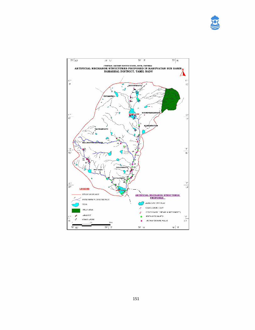
151
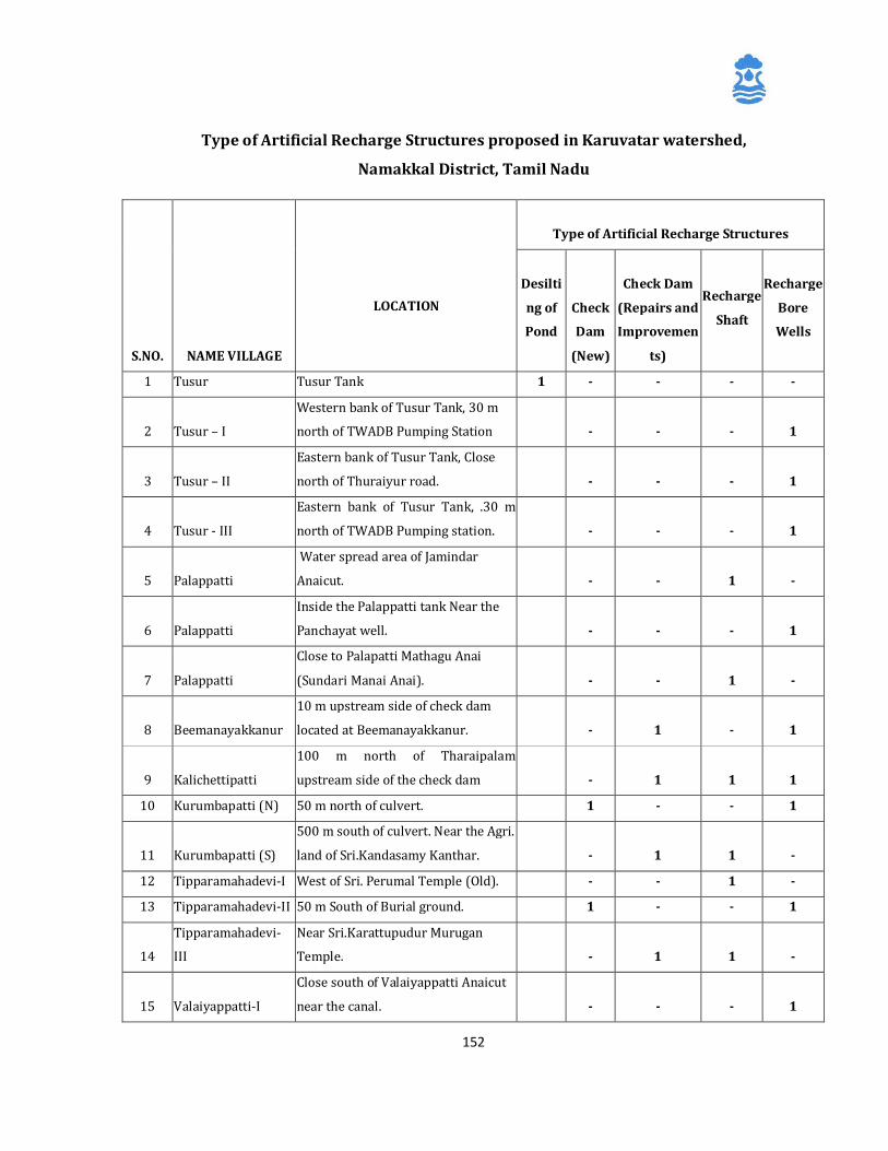
152
Type of Artificial Recharge Structures proposed in Karuvatar watershed,
Namakkal District, Tamil Nadu
S.NO. NAME VILLAGE
LOCATION
Type of Artificial Recharge Structures
Desilti
ng of
Pond
Check
Dam
(New)
Check Dam
(Repairs and
Improvemen
ts)
Recharge
Shaft
Recharge
Bore
Wells
1 Tusur Tusur Tank 1 - - - -
2 Tusur – I
Western bank of Tusur Tank, 30 m
north of TWADB Pumping Station
- - - 1
3 Tusur – II
Eastern bank of Tusur Tank, Close
north of Thuraiyur road.
- - - 1
4 Tusur - III
Eastern bank of Tusur Tank, .30 m
north of TWADB Pumping station.
- - - 1
5 Palappatti
Water spread area of Jamindar
Anaicut.
- - 1 -
6 Palappatti
Inside the Palappatti tank Near the
Panchayat well.
- - - 1
7 Palappatti
Close to Palapatti Mathagu Anai
(Sundari Manai Anai).
- - 1 -
8 Beemanayakkanur
10 m upstream side of check dam
located at Beemanayakkanur.
- 1 - 1
9 Kalichettipatti
100 m north of Tharaipalam
upstream side of the check dam
- 1 1 1
10 Kurumbapatti (N) 50 m north of culvert. 1 - - 1
11 Kurumbapatti (S)
500 m south of culvert. Near the Agri.
land of Sri.Kandasamy Kanthar.
- 1 1 -
12 Tipparamahadevi-I West of Sri. Perumal Temple (Old). - - 1 -
13 Tipparamahadevi-II 50 m South of Burial ground. 1 - - 1
14
Tipparamahadevi-
III
Near Sri.Karattupudur Murugan
Temple.
- 1 1 -
15 Valaiyappatti-I
Close south of Valaiyappatti Anaicut
near the canal.
- - - 1
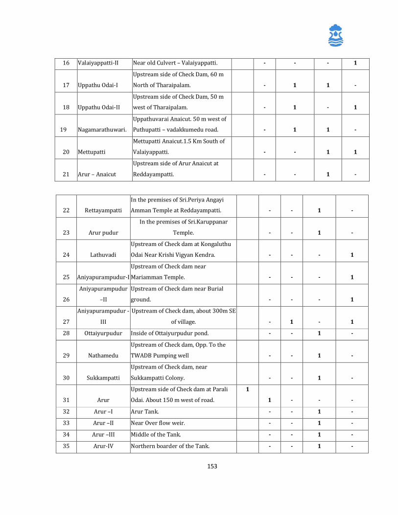
153
16 Valaiyappatti-II Near old Culvert – Valaiyappatti. - - - 1
17 Uppathu Odai-I
Upstream side of Check Dam, 60 m
North of Tharaipalam.
- 1 1 -
18 Uppathu Odai-II
Upstream side of Check Dam, 50 m
west of Tharaipalam.
- 1 - 1
19 Nagamarathuwari.
Uppathuvarai Anaicut. 50 m west of
Puthupatti – vadakkumedu road.
- 1 1 -
20 Mettupatti
Mettupatti Anaicut.1.5 Km South of
Valaiyappatti.
- - 1 1
21 Arur – Anaicut
Upstream side of Arur Anaicut at
Reddayampatti.
- - 1 -
22 Rettayampatti
In the premises of Sri.Periya Angayi
Amman Temple at Reddayampatti.
- - 1 -
23 Arur pudur
In the premises of Sri.Karuppanar
Temple.
- - 1 -
24 Lathuvadi
Upstream of Check dam at Kongaluthu
Odai Near Krishi Vigyan Kendra.
- - - 1
25 Aniyapurampudur-I
Upstream of Check dam near
Mariamman Temple.
- - - 1
26
Aniyapurampudur
–II
Upstream of Check dam near Burial
ground.
- - - 1
27
Aniyapurampudur -
III
Upstream of Check dam, about 300m SE
of village.
- 1 - 1
28 Ottaiyurpudur Inside of Ottaiyurpudur pond. - - 1 -
29 Nathamedu
Upstream of Check dam, Opp. To the
TWADB Pumping well
- - 1 -
30 Sukkampatti
Upstream of Check dam, near
Sukkampatti Colony.
- - 1 -
31 Arur
Upstream side of Check dam at Parali
Odai. About 150 m west of road.
1
1 - - -
32 Arur –I Arur Tank. - - 1 -
33 Arur –II Near Over flow weir. - - 1 -
34 Arur –III Middle of the Tank. - - 1 -
35 Arur-IV Northern boarder of the Tank. - - 1 -
154
Blockwise Details of Artificial Recharge Structures being constructed in
Karuvatar watershed, Namakkal District, Tamil Nadu
Recharge Shaft in namakkal District in Tamilnadu
36 Muthukapatti I In the premises of Thachan Anaicut. - - - 1
37 Muthukapatti-II
In the premises of Cheethakattu
Anaicut.
- - - 1
38 Salappalayam Upstream side of Check Dam. - - - 1
39 Palayapalayam In the premises of Palayapalayam Tank - - - 1
40 Sivanayakkampatti
In the premises of Sivanayakkampatti
Tank
- - 1 -
Total
02 02 08 20 20
S.No. Name of
blocks
Type of Artificial Recharge Structures
Desilting
of pond
Check
Dam
(New)
Check Dam
(Repairs and
Improvements)
Recharge
Shaft
Recharge
Bore Wells
1 Erumapatti 1 2 7 9 15
2 Mohanur 1 - - 11 2
3 Namakkal - - 1 - 3
Total 2 2 8 20 20
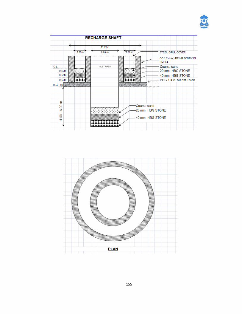
155
Construction design for the Recharge Shaft
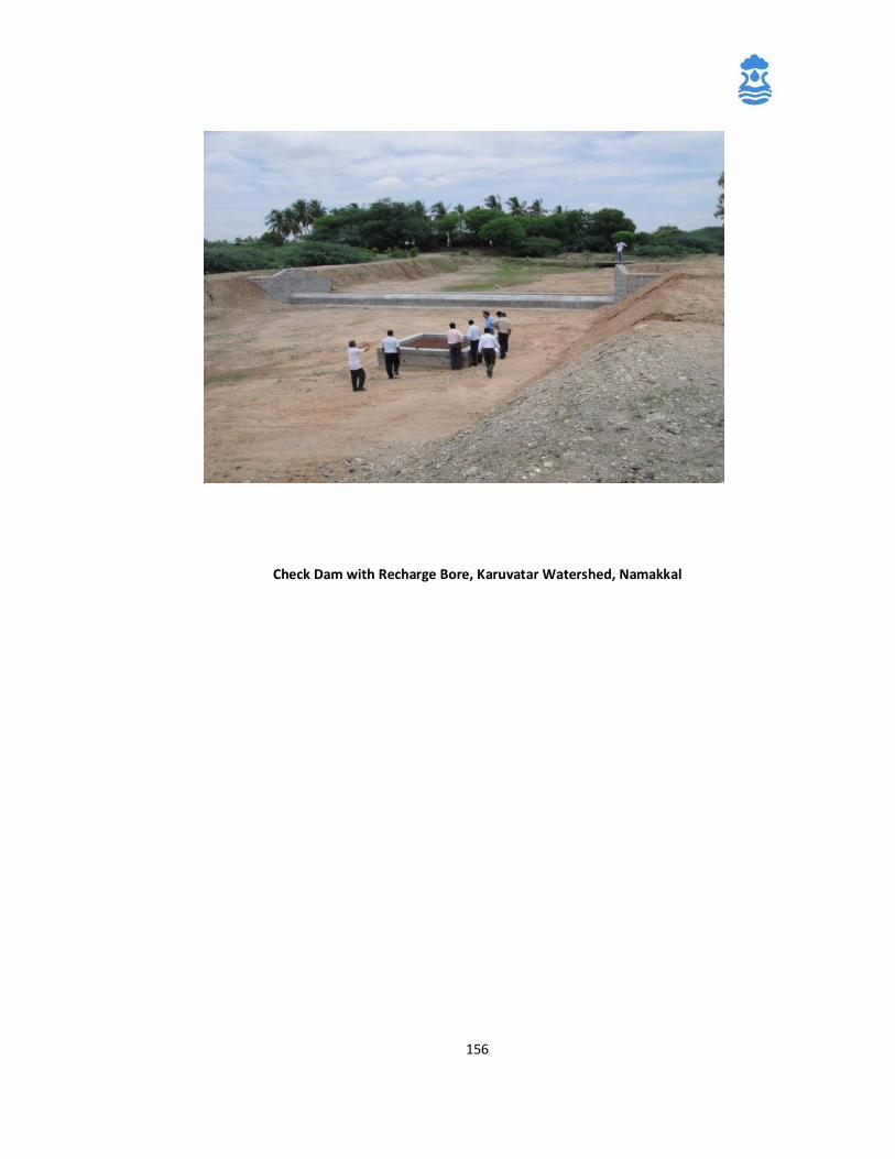
156
Check Dam with Recharge Bore, Karuvatar Watershed, Namakkal
157
Annexure-2
References used in this manual, suggested readings for Design elements for
sustainability structures, and sources recommended for further readings.
1. Rajiv Gandhi National Drinking water Mission- National Drinking water
Program- Framework for Implementation,
2. Manual on Artificial Recharge of Ground Water, CGWB, MOWR, 2007
3. “Water Harvesting and Artificial recharge” published by DDWS, Ministry of
Rural Development, Govt of India
4. ‘Guide on sustainability of drinking water source for implementers and the
users” published by Department of Drinking Water & Sanitation, GoI.
5. “Bringing Sustainability to Drinking Water Systems in Rural India” published
by Department of Drinking Water & Sanitation, Govt of India, 2007.
6. “Implementation manual on National Rural Water Quality Monitoring &
Surveillance Programme” published by Department of Drinking Water &
Sanitation.
7. Success stories and Case studies at
http://www.ddws.gov.in/documentreports/term/42
8. http://www.cseindia.org/
158
Annexure-3
List of Abbreviations used in the manual
GPS Global Positioning System
GP Gram Panchayat
GPs Gram Panchayats
PRI Panchayati Raj Institutions
MDWS Ministry of Drinking water and Sanitation
NRDWP National Rural Drinking Water Program
VWSC Village Water and Sanitation Committee


