",-~ ~, ,:,. : R. & M. No. 2803 (9714) (A.R.0. Teolmieal I~r0 ...... i .,-( MINISTRY OF SUPPLY AERONAUTICAL RESEARCH COUNCIL REPORTS AND MEMORANDA - . .... , -- . :. i ? . A Brief Review of the Problem of Exhaust Silencing F. L. W~.sr Crow~z Copyrig,~t Reserved LONDON: HER MAJESTY'S STATIONERY OFFICE I954 FOUR SHILLINGS NET
Transcript
",-~ ~, ,:,. :
R. & M. No. 2803 (9714)
(A.R.0. Teolmieal I ~ r 0
. . . . . . i
.,-(
MINISTRY OF SUPPLY
AERONAUTICAL RESEARCH COUNCIL REPORTS AND M E M O R A N D A
- . . . . . , -- . :.
i ? .
A Brief Review of the Problem of Exhaust Silencing
F. L. W~.sr
Crow~z Copyrig,~t Reserved
LONDON: HER MAJESTY'S STATIONERY OFFICE
I954
F O U R S H I L L I N G S N E T
A Brief Review of the Problem
F. L. W:EST
of Exhaust Silencing
COMMUNICATED BY THE PRINCIPAL DIRECTOR OF SCIENTIFIC RESEARCH (AIR), MINISTRY OF SUPPLY
Reports and Memoranda !Vo. 28 o 3"
May, 194 6
r
} . :. / - 2. ':."
Summary.--This note reviews past and present work on noise reduction of the reciprocating engine exhaust.
Collected measurements of t h e noise level surrounding various engine installations and the effect of silencing experiments on engine and aircraft performance are presented. In view of the growing application of the gas turbine, some recent observations of its noise characteristics are included.
The adverse effects of simple baffle silencers on engine power illustrate the need for renewed investigation of silencing by acoustical interference methods allowing unrestricted gas flow. In this respect, limitations of past work on the theory of silencers are discussed and possible improvements suggested.
In conclusion, a tentative method of calculating the influence of engine and exhaust pipe design on the noise spectrum is applied to a typical system.
1. Introduction.--During the war the trend of exhaust system development has been towards higher performance and lower weight without regard to any effects such development might have had on noise. In civil aircraft however the reduction of noise to bearable limits is of first importance.
In the past, efforts have been made to achieve some measure of silence, the criteria being maximum attenuation with a minimum exhaust back pressure and added weight, but the need to maintain useful exhaust thrust imposes a further condition, which demands a renewed and more thorough investigation of the problem.
Simple jet engines present a somewhat different problem to the conventional reciprocator but with certain modifications the general principles of noise reduction still apply.
111. Sensation Level and A2bparent Loudness.--Early acoustical theories at tempted to use the phon unit as a measure of sensation level. The system is hovcever of little use when analysis of a complex noise is required and it is preferable to deal with intensi ty in decibels on a frequency basis. As the ear is not equally sensitive to all frequencies, the loudness of a sound is not t ru ly represented by tile decibel scale and further, it is not always possible to reduce results to obtain overall noise levels ; but these minor faults are more than outweighed by the ease of application and the fact tha t overall noise levels are rarely of much scientific value.
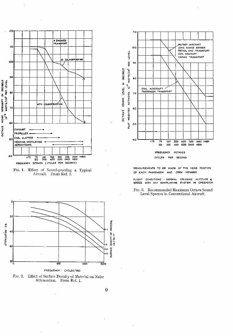
1.2. Silencing of Low _Frequency Noise.--The noise spectrum inside a conventional aircraft cabin is shown in Fig. 1 extracted from Ref. 1. Curve A is for an untreated cabin and B for a cabin soundproofed by standard methods with a material of about 0.5 lb/sq ft surface density. Fig. 2 shows how the at tenuat ing quali ty varies with surface density for an average sound proofing material. I t is considered tha t a material with the surface density stated above is the heaviest tha t can be economically used at present.
* R.A.E. Tech. Note Gas 20, received 13th June, 1946. (60496) A
From the curves it will be apparent that low-frequency noise cannot be satisfactorily reduced by soundproofing, any such reduction must therefore be achieved by suitable t reatment at the source.
1.3. Recommended Maximum Noise Level.---From comfort considerations it is necessary to specify the maximum allowable noise level in the aircraft cabin.
The maximum sound level spectrum recommended for a conventional aircraft cabiri is shown in Fig. 3 for measurements taken with a flat weighted network and a reference level of 10 -1" watt/sq cm.
An increased high-frequency noise intensi ty may have to be tolerated in jet-propelled aircraft owing to the greater level of noise generated in this region and the economical limiting surface density of the soundproofing material.
1.4. Exhaust Silencers.--The methods of reducing noise from a reciprocating engine exhaust by passing the pulsating gases through a silencer are well known. In most cases some form of baffle or constriction is present in tile gas stream with the consequent dissipation and loss of thrust. Such a design must therefore be abandoned and attention directed towards acoustical interference rather than reflection by baffles in order to disperse acoustic pulsations without restricting the gas flow.
Simple methods of interference by branched pipes are common, but owing to the pipe lengths involved a silencer of prohibitive size would be required to effect the fundamental frequency to any great extent.
1.5. Theoretical Approach.--From theoretical considerations the at tenuating characteristics of some types of acoustic filters can be predicted within the limits of the basic assumptions (Refs. 2 and 3).
Considering the close analogy between the passage of sound-waves through tubes and of a current through the equivalent electrical circuit, it should be possible to s tudy the acoustical properties of different silencer designs by applying tile advanced mathematics of electrical networks.
A method of calculating the wave form of the exhaust noise from the dimensions of the cylinder and exhaust pipe is also required for a full understanding of the piston engine noise problem.
2. Royal Aircraft Establishment Work on Silencing.--Experimental work at the R.A.E. prior to 1937 is described in R. & M. 1760 ~.
2.1. Silencing Trials of a Heyford Bomber.---The last comprehensive exhaust silencing experi- ments at the R.A.E. were made on a Heyford aircraft (2 Kestrel X engines).
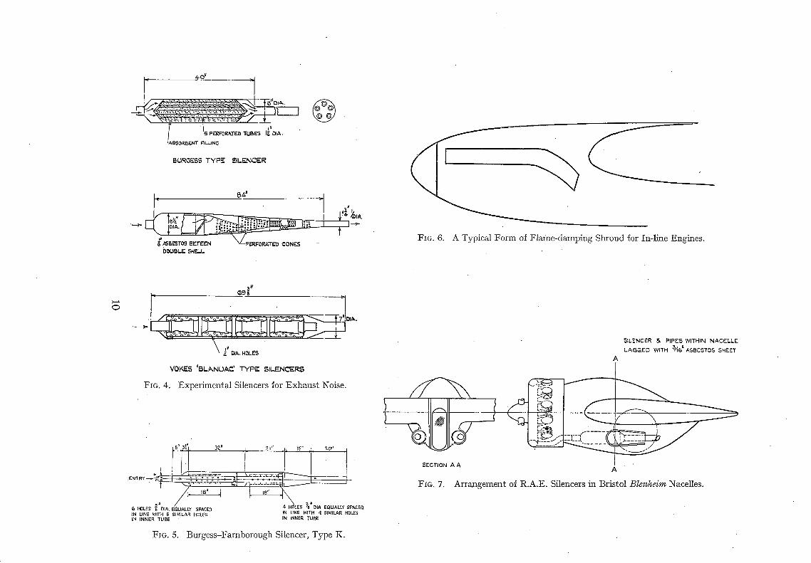
Test-bed measurements of a Kestrel engine fitted with type K Burgess-Farnborough silencers gave a noise reduction of 24 B.S. phons with a back pressure of 0.5 lb/sq in. at full throttle (225 b.h.p, per silencer), and subsequently satisfactory flight tests were obtained on the He)ford, but it was found that the silencing modifications, which included new propellers, were too heavy for service use (Ref. 5).
This experiment serves as a good example of what may happen when an at tempt is made to reduce the propeller and engine noise on an existing aircraft. To reduce the propeller tip speed a heavier propeller and larger reduction gear were required. This necessitated two extra engine mounting feet to support the gear so that larger engine mountings were necessary. The extra engine and propeller weight plus the silencers then made it necessary to stiffen parts of the wing structure. As a result of the weight additions forward of the c.g. it became necessary to add ballast to the tail. The net result was a decrease in useful load out of all proportion to the silencing achieved.
2.2. Trainer Aircraft Silencing.--In an at tempt to reduce the aural disturbance in the region of training aerodromes, various experimental silencers were fitted to trainer aircraft at R.A.E. and the resulting noise reduction and loss of performance were measured (Refs. 6, 7 and 8).
2
Three types of silencer were tested, the Burgess, Vokes ' Blanvac ' and R.A.E. (Figs. 4 and 5), noise measurements being made from the ground with the aircraft flying a straight and level course at 500 ft altitude to pass directly overhead of the recording apparatus. The results obtained are summarised in Appendix I.
Consistent results are not apparent for each design of silencer owing to the wide variation of size to accommodate the exhaust discharge mass from the respective engines. General results indicate the Vokes silencer to be overbaffled which should give good at tenuation of low-frequency noise but involves excessive back pressure and develops predominant high-frequency bands in the transmission.
These experiments supply good quanti tat ive data on the effects of exhaust silencers on aircraft performance, but failing a frequency analysis of the transmitted spectra the actual merits of the respective silencers from the acoustic aspect cannot be fully appreciated.
2.3. Silencing Trials of a Bristol 142 Aircraft.--Flight tests were made during 1937 on a Bristol 142 aircraft (2 Mercury engines). The object here was to t ry to obtain some measure of low- frequency silencing in order to improve the general noise level in the aircraft although calculations indicated that no overall reduction could be expected on account of the high propeller-tip speed.
The starboard engine was fitted with Burgess-Farnborough silencers enclosed within the engine nacelle (Fig. 7) while the port engine exhausted into the standard collector ring. Each silencer weighed 40 lb making a total of 80 lb added to the weight of the aircraft.
Noise measurements taken in flight first with the silenced engine at full power and the unsilenced one thrott led right back and then vice versa indicated tha t the noise intensi ty was unaffected.
There was apprehension over the additional fire risk due to installing the silencers inside the engine nacelle despite their asbestos lagging, and small louvres in the cowling were found necessary for ventilation of the nacelle. Under flight conditions the temperature of the silencer lagging was about 215 deg C and reached a maximum value of 300 deg C approximately one minute after landing the aircraft and stopping the engine. The temperatures within the nacelle, measured in case of ill effects to the landing gear, where found to reach a maximum of 31 deg C.
The experiment gave no useful cabin silencing and the scheme was abandoned.
3. Experiments on the Acoustical Features of Exhaust Silencers.--3.1. Model Experiments.-- In an at tempt to correlate the results of a tentative theory 3 of the acoustical features of exhaust silencers with practice, experiments were made at the National Physical Laboratory on model silencers considering primarily acoustic flow Mone 9 but subsequently with a steady flow of air imposed I° to similate the exhaust discharge from an engine.
Considering the acoustic flow only, sounds of various frequencies covering the audible scale of pitch were introduced at the inlet to the silencer, and observations made of the sound.transmitted. Fig. 8 shows the good agreement between calculated and observed attenuation for a 4-section baffle silencer and a Stewart low-pass filter.
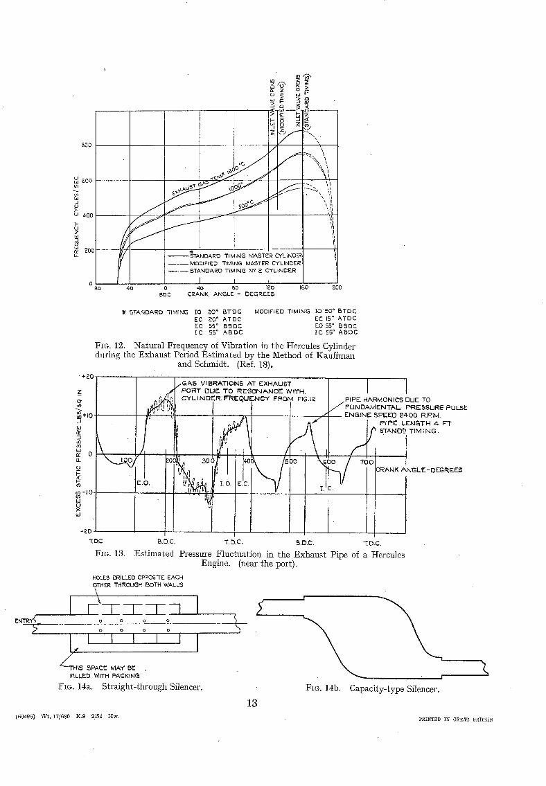
The presence of an air flow through the silencer, induced in the case of the experiments by means of a fan at the entry end of the Silencer, showed an appreciable modification in the at tenuating characteristics of the baffle silencer in particular. For baffles having but few holes the effect of the air flow is to increase at tenuation (Fig. 9), mainly at low frequencies. This increase is of the order calculable from an approximate formula put forward by Griffith I~ but agreement is not uniformly good. For straight-through silencers (Fig. 14) including the Stewart type, air flow had negligible effect on the performance.
3.2. Full-Scale Silencers.--Tests were made on a Kestrel engine at the R.A.E. in collaboration with the National Physical Laboratory who made the noise measurements. The primary object of the investigation was to determine by objective measurements the variation with frequency of
3 ( 6 0 4 9 6 ) " A *
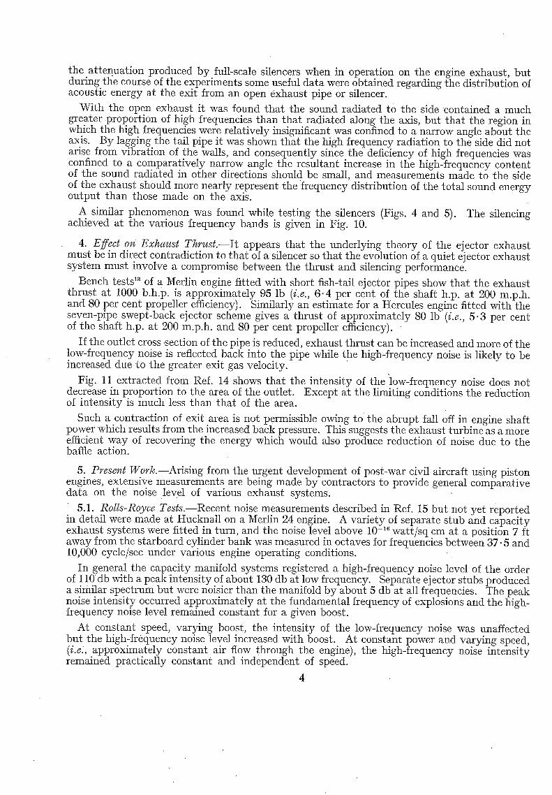
the attenuation produced by full-scale silencers when in operation on the engine exhaust, but during tl~e course of the experiments some useful data were obtained regarding the distribution of acoustic energy at the exit from an open exhaust pipe or silencer.
With the open exhaust it was found that the sound radiated to the side contained a much greater proportion of high frequencies than that radiated along the axis, but tha t the region in which the high frequencies were relatively insignificant was confined to a narrow angle about the axis. By lagging the tail pipe it was shown that the high frequency radiation to the side did not arise from vibration of the walls, and consequently since the deficiency of high frequencies was confined to a comparatively narrow angle the resultant increase in the high-frequency content of the sound radiated in other directions should be small, and measurements made to the side of the exhaust should more nearly represent the frequency distribution of the total sound energy output than those made on the axis.
A similar phenomenon was found while testing the silencers (Figs. 4 and 5). The silencing achieved at the various frequency bands is given in Fig. 10.
4. Effect on Exhaust Thrust .--I t appears that the underlying theory of the ejector exhaust must be in direct contradiction to tha t of a silencer so that the evolution of a quiet ej ector exhaust system must involve a compromise between the thrust and silencing performance.
Bench tests 1'~ of a Merlin engine fitted with short fish-tail ejector pipes show that the exhaust thrust at 1000 b.h.p, is approximately 95 lb (i.e., 6.4 per cent of the shaft h.p. at 200 m.p.h. and 80 per cent propeller efficiency). Similarly an estimate for a Hercules engine fitted with the seven-pipe swept-back ejector scheme gives a thrust of approximately 80 lb (i.e., 5 .3 per cent of the shaft h.p. at 200 m.p.h, and 80 per cent propeller efficiency).
If the outlet cross-section of the pipe is reduced, exhaust thrust can be increased and more of the low-frequency noise is reflected back into the pipe while the high-frequency noise is likely to be increased due to the greater exit gas velocity.
Fig. 11 extracted from Ref. 14 shows that the intensity of the "low-frequency noise does not decrease in proportion to the area of the outlet. Except at the limiting conditions the reduction of intensity is much less than that of the area.
Such a contraction of exit area is not permissible owing to the abrupt fall off in engine shaft power which results from the increased back pressure. This suggests the exhaust turbine as a more efficient way of recovering the energy which would also produce reduction of noise due to the baffle action.
5. Present Work.--Arising from the urgent development of post-war civil aircraft using piston engines, extensive measurements are being made by contractors to provide general comparative data on the noise level of various exhaust systems.
5.1. Rolls-Royce Tests.--Recent noise measurements described in Ref. 15 but not yet reported in detail were made at Hucknall on a Merlin 24 engine. A variety of separate stub and capacity exhaust systems were fitted in turn, and the noise level above 10 -16 watt/sq cm at a position 7 ft away from the starboard cylinder bank was measured in octaves for frequencies between 37.5 and 10,000 cycle/sec under various engine operating conditions.
In general the capacity manifold systems registered a high-frequency noise level of the order of 110 db with a peak intensity of about 180 db at low frequency. Separate ej ector stubs produced a similar spectrum but were noisier than the manifold by about 5 db at all frequencies. The peak noise intensity occurred approximately at the fundamental frequency of explosions and the high- frequency noise level remained constant for a given boost.
At constant speed, varying boost, the intensity of the low-frequency noise was unaffected but the high-frequency noise level increased with boost. At constant power and varying speed, (i.e., approximately constant air flow through the engine), the high-frequency noise intensity remained practically constant and independent of speed.
A further series of tests with exhaust systems having reduced outlet areas were not very conclusive but it did appear that restricting the exit area caused a definite reduction of low- frequency noise intensity and increased the high-frequency level.
5.2. Bristol Aircraft Compa~y.~The Bristol Aircraft Company has recently made ground test comparisons of noise intensity inside a Beaufighter fuselage using the port engine (Hercules xvII) fitted with various exhaust systems and a De Havilland 4-blade (thin) propeller TM.
Comparative data is presented in Ref. 16 for each exhaus t sys tem showing the increase in noise with engine power at constant crankshaft speed conditions, both for overall (flat response) noise level and in the various frequency octaves from 37.5 to 1200 cycle/sec.
At all conditions the respective power outputs for each exhaust system are within :~ 30 b.h.p. the same, a front exhaust manifold with single outboard tail pipe being the quietest at all powers and r.p.m, while open rear-swept stubs are the noisiest. An intermediate system consisting of a rear collector ring having five outlets with either fish-tail or ' g ra te r ' end fitments attached is considered the most suitable for it part ly achieves the low-frequency noise suppression characteristic of the single-exit manifold while maintaining engine power comparable with the separate ejector system. This rear collector ring should not have the unsatisfactory effect on the engine cooling associated in the past with the front collector ring.
Considering the overall noise intensity, both the outlet arrangements on the rear manifold gave noise levels of 3 db greater than the front manifold while a 7 db increase was recorded with the open stubs. With the front manifold system it appeared that the major noise was from the propeller. As a tentative figure an increase of 300 b.h.p, at constant r.p.m, or 400 r.p.m, at constant' power involves an increase in general noise level of 3 db (from 100 db at 1600 r.p.m, and 400 b.h.p.).
The frequency analysis of the cabin noise indicated a low-frequency intensity of about 105 db and neither a change of power nor substitution of another exhaust varied the mean figure by more than 4- 3 db. This suggests that the noise levels of both the propeller and exhaust were almost equal in this frequency region and consequently efforts have to be made to modify tile propeller before any appreciable reduction of noise can be achieved by exhaust silencing.
5.3. Simple Jet Engims.--In connection with the sound proofing of gas turbine engine test houses the National Physical Laboratory have recently carried out some noise measurements on simple jet engines at Power Jets Ltd., Whetstone. The measurements were not t ruly characteristic of the spectra to be expected in flight, but in the absence of flight data the results are of some interest.
Rather surprisingly a frequency analysis of the incident noise produced a spectrum very similar both in ultimate and relative intensities of the frequency octaves to that expected from a conventional engine of comparable power output. Notable features were the absence of the definite peak intensity prominent at the firing frequency of the reciprocator and the rather iower high-frequency level than one would be led to expect from aural listening. This latter feature can however be at tr ibuted to the absorptive material present in the test house.
The distribution of sound energy around a jet of air has been investigated at Rolls Royce Ltd. A nozzle of throat diameter 1 in. was chosen for the tests and the pressure ratio across the nozzle varied in order to study the effects of jet velocity on noise intensity of the component tones. Searchwi th a recording microphone detected a local source of low-frequency noise about 3 It from the nozzle on the axis Of the jet, and as in the case of the exhaust pipe (section 3.2) a preponderence of high-frequency components existed at the side of the jet. By traversing the sound field with the recording microphone following a semi-circular path, nozzle exit as source, it was verified that the mean of all the measurements could be represented very closely by the /'eadings taken at 45 deg to the jet axis from the source.
5
Variation of the nozzle pressure ratio up to the critical value led to the conclusion tha t the noise intensity was proportional to (jet velocity)" where the index n varied between 4 and 8 for low- or high-frequency tones respectively.
An experimental silencing scheme in the form of a venturi shroud leading to a silencing chamber w a s now presented throat forward to the nozzle in order to surround the air jet. About 30 db noise reduction was achieved by this means and it was shown that axial adjustment of the linear distance between the nozzle exit and the rear end of the shroud between ½ in. and 3 in. had negligible effect on the transmission. This fact may be of major importance as it would appear tha t little or no sound energy is propagated from a gas jet until turbulent mixing with the surrounding medium is established.
6. Theoretical Work.--6.1. Past Acoustical Theory.--Early theories on the action of acoustic filters, of the baffle type, though successful in ideal cases (Fig. 8) when applied to exhaust silencing have proved inadequate for explaining experimental results. This is clearly due to errors arising from the basic assumptions.
In the theory the effects of viscosity dissipation and temperature gradients within the acoustic filter circuit are neglected. Within the limits recorded in practice, only a slight error in the esti- mated attenuation is expected from temperature variation, but viscosity, especially with orifices or perforations of small diameter can cause appreciable reduction of intensity dependent on the frequency of the acoustic vibration. A further necessary assumption restricts the application of the simple formulae to filters whose dimensions are small compared with the wave length, the physical limitation being tha t the medium within a capacity chamber is considered to vibrate as a whole with uniform sectional velocity distribution. At the higher frequencies of incident noise, the transmission cannot be predicted with any degree of confidence on this account. Pressure distribution again is assumed uniform in any one chamber of the filter.
The acoustic properties Of a baffle-type silencer will be affected by the presence of a steady flow. The classical theory was modified by Griffith ~ to take account of this and much more rational results were claimed, but the model experiments by Davis and Fleming 11 showed incon- sistent agreement with Grifflth's theory (Fig. 9), leaving discrepancies not yet satisfactorily explained. Finally, present theories assume a completely inert outer case and baffles. Shell and diaphragm vibrations may have an important influence on the action of the acoustic filter and an exact theory must necessarily take them into account.
6.2. Analogy with Electrical Circuits.--The close analogy between acoustical filter problems and the action of alternating currents in equivalent electrical circuits is well known. In the modern developments in the electrical theory the errors introduced by simplifications analogous to these iust described for the acoustic filter theory are overcome by an appropriate adjustment of the impedances of the various branches of the network. There is a possibility that errors in the present acoustical theories could be eliminated by similar methods.
6.3. Analysis of Exhaust Noise of Piston Engines.--Kauffman and Schmidt ~7 have put forward a method for obtaining the frequency of the component tones contained in the exhaust noise spectrum of a piston engine, but without an experimental frequency analysis of the noise the relative intensi ty at each frequency cannot be determined by their methods. Pressure pulses excited by the mass discharge" from the cylinder set up vibrations. . of the column18 of gas in the exhaust pipe and have a marked effect on the acoustic transm~sslon. Kastner has developed a method to estimate the amplitude of this pulse by a series of successive approximations. For a given engine and exhaust pipe tile variation of wave form and relative amplitude of the funda- mental pressure wave with engine speed and power output can be obtained. It will be appreciated tha t the transmitted noise intensity is dependent primarily on the pressure fluctuation inside the pipe. Therefore if the complete pressure-wave including disturbances due to ' edge tones '
6
and the resonator effect of Kauffman and Schmidt can be determined from theoretical considera- tions, it becomes possible to predict the external noise intensity from the design details and operating conditions of the engine.
An at tempt has been made to apply Kauffman and Schmidt 's and Kastner's methods to a Hercules engine. Fig~ 12 illustrates the estimated frequency of acoustic resonance at the exhaust port while Fig. 13 shows the mean variation of exhaust pipe pressure. The cylinder resonance vibrations will be superimposed on the mean pressure-wave and their frequency can be determined from Fig. 12 but the relative amplitudes present a more formidable problem. Stewart 2 gives an expression (p. 51) for the magnification factor of the ideal cylinder resonator but consider- able experimental data is necessary before the application to the Hercules can proceed further.
. . Principles of Sound Control in Aeroplanes. Crnft Laboratory, Harvard University. O.S.R.D. 1543. 1944.
. . Acoustics. D. Van Nostrand Coy. Inc., New York.
.. Acoustical Theory of the Exhaust Silencer, Particularly of the Baffle Type. Physics Dept. N.P.L. 1933. A.R.C. Report 389.
. . Progress of Experiments in Aero-Engine Exhaust Silencing. R. & 1Vi. 1760. 1937.
. . Note on Noise and Performance Tests of a Silenced Heyford Airplane. A.R.C. Report 1681. March, 1935.
. . Flight Tests of Silencers for Tiger Moth Aeroplanes. A.R.C. Report 3157. July, 1937.
. . Flight Tests of Silencers for Tutor Aeroplanes. A.R.C. Report 3156. July, 1937.
.. Flight Tests of Silencers for Har t Trainer Aeroplanes. A.R.C. Report 3155. June, 1937.
. . Progress Report oi1 Model Experiments Concerning Acoustical Features of Exhaust Silencers. A.R.C. Report 1118. March, 1934.
. . Further Model Experiments Concerning the Acoustical Features of Exhaust Silencers. A.R.C. Report 1421. February, 1935.
.. The Attenuation Characteristics of Some Aero-Engine Exhaust Silencers. A.R.C. Report 2249. February, 1936.
.. Note on the Action of Baffle Silencers. A.R.C. Report 1129. February, 1984.
B. Exhaust Ejector Tests of a Merlin 46 Engine. A.R.C. Report 7624. February, 1944.
.. The Problem of Exhaust Silencing and Engine Efficiency. Proc. I . A . E . , Vol. XXVII , p. 614. March, 1983.
•. The Silencing of Aircraft. Proc. R.Ae.S . April, 1946.
Ltd. Ground Test Comparisons of Noise Intensi ty Inside a Beaufighter Fuselage. Interim development report H17/BFR.11/JL.955/1 .
. . Schalld~mpfer f u r AutomobiImoteren. M. Krayn. Berlin. 1932.
.. A Study of the Release Process in a Four-Stroke Engine including an Investigation of Conditions both in the Engine Cylinder and in the Exhaust Port. Manchester University.
7 (60496) A **
APPENDIX I
Trainer Aircraft Silencing
Tiger Moth Trainer (Gipsy Major engine).--The Vokes ' Blanvac ' silencer gave the greatest noise reduction but resulted in an undue increase in exhaust back pressure (2 lb/sq in. at full throttle) and loss of performance (13½ per cent rate of climb and 4 m.p.h, speed).
A decrease of between 8½ and 10 B.S. phons when the aircraft was directly overhead and 5½ to 6 phons on either flank was achieved with the Burgess silencer which involved a loss of 8 per cent in optimum rate of climb and 1 m.p.h, maximum speed. The observed increase of exhaust back pressure was negligible.
The R.A.E. silencer was slightly less efficient than the Burgess, giving a noise reduction of 6 to 8½ phons overhead and between 4 and 5½ phons on the flank. A back pressure of about 0 .2 lb/sq in. was observed, the effect on performance being 9½ per cent in rate of climb and 4 m.p.h, in speed.
Tutor Aircraft (Lynx IV engine).--Using the standard exhaust collector ring for reference purposes comparative noise measurements indicated slight superiority of the Burgess silencer over the R.A.E. type as regards noise reduction and performance. The Vokes silencer increased the noise with the engine port thrott led and was considered unsuitable.
Performance tests showed a reduction of 8 per cent. in the optimum rate of climb with the Burgess and Vokes silencers and 13 per cent with the R.A.E., whilst the maximum level speed at 3000 ft was decreased by 2½, 2½, and 1 m.p.h., the increase of back pressure being 0.2, 1.1, and 0.3 lb/sq in. respectively.
Hart Trainer (Kestrel 1B engine).--The R.A.E. and Vokes silencers gave almost equally good noise reductions (9 to 11 phons) when compared with the standard system of down-swept pipes for the same parasitic cost, while the Burgess type achieved only about 4 phons for a greater loss of performance.
Regarding flying performance the optimum rate of climb was reduced 7 per cent by the R.A.E. and Vokes silencers and by 11 per cent in the case of the Burgess. Maximum level speed was decreased by 5, 3{ and 5 m.p.h, respectively with a corresponding increase of exhaust back pressure of 1, 1-2 and 1 lb/sq in.
On this machine the silencers rendered entrance to and exit from the aeroplane difficult to the crew especially when the metal was hot. This could be overcome by fitting them below the wings which however would increase the risk of fire in the event of undercarriage failure, a point of some importance in the case of trainer planes.
FIG. 12. Natural Frequency of Vibration ill the Hercules Cylinder during the Exhaust Period Estimated by the Method of Kauffman
mid Schmidt. (Ref. 18).
~ - - f G A S VIBRATIONS AT E X H A U S T - - ] 1 ,#' PORT DUE TO R E S O N A N C E WITH. | I
~,,'; C Y L I N D E R . F R E Q U E N C Y FROM F'IG.12 PiPE HARMONICS DUE TO . , i i,l~i ~ / F L L I N I D A M E N T / k L PRESSURE PULSE
"-~. I ' - - - - ~ - - - - - - - 7 L - - ENGINE SPEED 84.00 IR.P.M. L ,,~ .d I I a " [ P i P E L E N G T H 4- F T I; ~j,.~-r I ] t~, I t ~ STANIDt2 T I M I N G .
L_ J_ '~,~'1 ~ t [ 1 1 \ / ] ' " - ~ / I I CRANKANGLE-DEGREEs
I:.%;.,.,L I , , , ~-gl " r o t 1 It I I ; ; t ~ M , M I . . . . . . . . I I / , r l - - I I
2 : J X U B.DC. T.O.C. B.O.C. "ZD.C.
Estimated Pressume Fluctuation m the Exhaust Pipe of a Hercules Engine. (near the port).
HOLES DRILLED OPPOSI'i'E EACH OTHER THROUGH BOTH WALLS
l--~-T--1 1 l o o o o
o o o o
I I I I I I
HIS SPACE MAY BE FILLED WITH PACKII'4G
FIG. 14a. Straight-through Silencer. I
FIG. 14b. Capacity-type Silencer.
13
\
t60496) Wt. 17/680 K.9 2/54 Hw. PRINTED IN GREAT BRITAIN
Re & Mo MOo 2803
Yubtica6ons of Aeronsudcs][ Research
the Council
ANNUAL TBCHNffCAL IZBPO~T~ OF THE AERONAUTffCAL I~E~EAIkC~ff COUNC]IL (BOUND VOLY@~IEg)
I936 Vol. I. Aerodynamics General, Performance, Airscrews, Fluttel" and Spinning. 4as. (4as. 9d.) Vol. II. Stabihty and Control, Structures, Seaplanes, Engines, etc. ~;os. (5as. iod.)
1937 Vol. L Aerodynamics General, Performance, Airscrews, Flutter and Spinning. 4as. (4as. Iod.) VoL II. Stability and Control, Structures, Seaplanes~ Engines, etc. 6as. (6IS.)
1938 Vol. L Aerodynamics General, Performance, Airscrews. 5as. (5is.) VoL !I. Stability and Control, Flutter, Structures; Seaplanes, Wind Tunnels, Materials. 3as.
(3os. 9d.)
1939 Vol. I. Aerodynamics General, Perkormance, Airscrews, Engines. 5os. (5os. txd.) VoL II. Stability and Control, Flutter and Vibration, Instruments, Structures, 8enplanes, etc.
63s. (643. 2d.)
x94o Aero and Hydrodynamics, Aero£oils, Airscrews, Engines, Flutter, Icing, Stability and Control, 8tructures, and a miscellaneous section. 5 °£ (5 IS.)
{941 Aero and Hydrodynamics, Aerot~oils, Airscrews, Engines, Flutter, Stability and Control, Structures. 63s. (64< ad.)
1942 Vol. L Aero and Hydrodynamics, Aero£oils, Airscrews, Engines. 75s. (7 @. 3d.) Vol. II. Noise, Parachutes, Stability and Control, Structures, Vibration, Wind Tunnds
47 s. 6d. (483. 5,/.) 1943 Vol. L (In tYze press.)
Vol. II. (In the press.)
ANNUAL ]~kEIPOFkT5 elf THB A~ONAUT~CAL ~kESE_~C}II COUNC~L-- 1933-34 IS. 6d. (is. 8d.) i937 zs. (2s. zd.) 1934-35 Is. 6d. (Ia. 8d.) I938 Is. 6d. (Is. 8d.)
April ~, 1935 to Dee. 3x, 1936. 4 s. (4 s. 4d.) 1939-48 33. (3s- 2d.)
~ND~X TO ALL IIEPO~T5 AND I'x~EBIORANDA PUBLiSHeD ~N THE ANNUAL T~CHN]tCAL REPOI~TS~ AND 5EPARATEL~_(--
April, 195o - R. & M. No. 2600. 2s. 6d. (as. 7½d.)
~bqDBXE$ TO T H E T B C H N ~ C A L ~EPORT5 O~ ¢ T H B AB~ONAUT~CAL ]~Z~BAB~C~{ C O U N C ] I L - -
December I, I936- -June 30, 1939. July I, I 939 - - june 3 o, 1945. July I, 1945 - - June 3 o, 1946. July I, 1 9 4 6 - December 3~, I946. January I, x 9 4 7 - June 30, t947. July, I95n
R. & M. No. 185o. R. & M. No. 195o. R. & M. No. 2050. R. & M. No. 215o. R. ~5 M. NO. 22~0. R. & M. No. 2350.
rs. 3d. (lS. 4½d.) Is. (Is. !½,/.) u. (13. 1½d.) is. 3d. (1s. 4½d.) Is. 3d. (IS. 4½d.) Zs. 9 d. (IS. Io½d.)
Prices in brackets include postage.
Obtainable from
H E R M A J E S T Y ' S S T A T I O N E R Y O F F I C E 'York House, Kingsway, London, W.C.2; 423 Oxford Street, London, W.1 (Post Orders : P.O. Box 569, London, S.E.1) ; 13a Castle Street, Edinburgh 2 ; 39, King Street, Manchester, 2 ; 2 Edmund Street, Birminghara 3 ; 1 St. Andrew% Crescent, Cardiff; Tower Lane, Bristol 1;
80 Chichester Street, Belfast, or through any bookseller