46
MiniView™ DVI 2/4 PORT USB KVMP Switch User Manual (GCS1762 / GCS1764) ®

MiniView™DVI 2/4 PORT USB KVMP SwitchUser Manual (GCS1762 / GCS1764)
®

Thank you for purchasing one of the most feature-rich DVI KVM with USB peripheral sharing and audiotechnology on the market. You can save money and space by eliminating the need for multiple DVI monitors,keyboards, mice, and USB peripheral devices such as printers, scanners, and more. Up to 127 USBdevices can be daisy chained from this KVMP switch. Sharing speakers and a microphone also offers extravalue and convenience for the users.
USB and KVM technology together makes cross-platform management easy. A single USB console cancontrol a PC and a MAC workstation, and share peripherals and audio between the computers.
We hope you enjoy using your Miniview DVI USB KVMP switch, yet another first-rate connectivity solutionfrom IOGEAR
©2005 IOGEAR. All Rights Reserved. PKG-M0140
IOGEAR, the IOGEAR logo, are trademarks or registered trademarks of IOGEAR, Inc. Microsoft and Windows are registered trademarks of MicrosoftCorporation. IBM is a registered trademark of International Business Machines, Inc. Macintosh, G3/G4 and iMac are registered trademarks of AppleComputer, Inc. All other brand and product names are trademarks or registered trademarks of their respective holders. IOGEAR makes no warranty of anykind with regards to the information presented in this document. All information furnished here is for informational purposes only and is subject to changewithout notice. IOGEAR, Inc. assumes no responsibility for any inaccuracies or errors that may appear in this document.
Welcome
Table of Contents
○ ○ ○ ○ ○ ○ ○ ○ ○ ○ ○ ○ ○ ○ ○ ○ ○ ○ ○ ○ ○ ○ ○ ○ ○ ○ ○ ○ ○ ○ ○ ○ ○ ○ ○ ○ ○ ○ ○ ○
02
03
04
05
06
10
13
15
29
37
38
40
41
42
○ ○ ○ ○ ○ ○ ○ ○ ○ ○ ○ ○ ○ ○ ○ ○ ○ ○ ○ ○ ○ ○ ○ ○ ○ ○ ○ ○ ○ ○ ○ ○ ○ ○ ○ ○
○ ○ ○ ○ ○ ○ ○ ○ ○ ○ ○ ○ ○ ○ ○ ○ ○ ○ ○ ○ ○ ○ ○ ○ ○ ○ ○ ○ ○ ○ ○ ○ ○ ○ ○ ○ ○ ○ ○ ○
○ ○ ○ ○ ○ ○ ○ ○ ○ ○ ○ ○ ○ ○ ○ ○ ○ ○ ○ ○ ○ ○ ○ ○ ○ ○ ○ ○ ○ ○ ○ ○ ○ ○
○ ○ ○ ○ ○ ○ ○ ○ ○ ○ ○ ○ ○ ○ ○ ○ ○ ○ ○ ○ ○ ○ ○ ○ ○ ○ ○ ○ ○ ○ ○ ○ ○ ○ ○ ○ ○ ○
○ ○ ○ ○ ○ ○ ○ ○ ○ ○ ○ ○ ○ ○ ○ ○ ○ ○ ○ ○ ○ ○ ○ ○ ○ ○ ○ ○ ○ ○ ○ ○ ○ ○ ○ ○
○ ○ ○ ○ ○ ○ ○ ○ ○ ○ ○ ○ ○ ○ ○ ○ ○ ○ ○ ○ ○ ○ ○ ○ ○ ○ ○ ○ ○ ○ ○ ○ ○ ○ ○ ○ ○
○ ○ ○ ○ ○ ○ ○ ○ ○ ○ ○ ○ ○ ○ ○ ○ ○ ○ ○ ○ ○ ○ ○ ○ ○ ○ ○ ○ ○ ○ ○ ○ ○ ○ ○ ○ ○ ○ ○
○ ○ ○ ○ ○ ○ ○ ○ ○ ○ ○ ○ ○ ○ ○ ○ ○ ○ ○ ○ ○ ○ ○ ○ ○ ○ ○ ○ ○ ○ ○ ○ ○
○ ○ ○ ○ ○ ○ ○ ○ ○ ○ ○ ○ ○ ○ ○ ○ ○ ○ ○ ○ ○ ○ ○ ○ ○ ○ ○ ○ ○ ○ ○ ○ ○ ○ ○ ○ ○ ○ ○
○ ○ ○ ○ ○ ○ ○ ○ ○ ○ ○ ○ ○ ○ ○ ○ ○ ○ ○ ○ ○ ○ ○ ○ ○ ○ ○ ○ ○ ○ ○ ○ ○ ○ ○ ○
○ ○ ○ ○ ○ ○ ○ ○ ○ ○ ○ ○ ○ ○ ○ ○ ○ ○ ○ ○ ○ ○ ○ ○ ○ ○ ○ ○
○ ○ ○ ○ ○ ○ ○ ○ ○ ○ ○ ○ ○ ○ ○ ○ ○ ○ ○ ○ ○ ○ ○ ○ ○ ○ ○ ○ ○ ○ ○ ○ ○ ○ ○ ○
Package Contents
Overview
Features
System Requirements
Introduction
Installation
Basic Operation
Hotkey Operation
Firmware Upgrade Utility
Appendix
Specifications
Technical Support
Radio & TV Interference Statement
Limited Warranty ○ ○ ○ ○ ○ ○ ○ ○ ○ ○ ○ ○ ○ ○ ○ ○ ○ ○ ○ ○ ○ ○ ○ ○ ○ ○ ○ ○ ○ ○ ○ ○ ○ ○ ○ ○ ○
2
Package Contents
This package contains:
1 x GCS1762 or GCS1764 KVMP Switch2 x Custom 6’ KVM Cables (GCS1762)4 x Custom 6’ KVM Cables (GCS1764)1 x Firmware Upgrade Cable1 x Power Adapter1 x User Manual1 x Quick Start Guide
Check to make sure that all the components are present and that nothing was damaged in shipping. If youencounter a problem, contact your dealer.
Read this manual thoroughly and follow the installation and operation procedures carefully to prevent anydamage to the unit, and/or any of the devices that connect to it.
3
Overview
The GCS1762/GCS1764 DVI KVM Switch charts a revolutionary new direction in KVM switch functionality bycombining a switch with a 2 port USB hub at the same time as it provides an interface for a digital monitor(DVI). The new IOGEAR GCS1762/GCS1764 enhances some of the great features found in the MiniViewKVM line and adds DVI technology into the mix.
The independent (asynchronous) switching feature, allows the KVM focus to be on one computer while theUSB peripheral/Audio focus is on another computer. This gives the user greater control over and moreflexibility. It also eliminates the need to purchase a separate USB hub as well as additional speakers set foryour other computers; thus reducing cost and maximizing user space.
The Miniview DVI USB KVMP Switch fully supports the DVI specification for both digital video input (flat paneldisplays, data projectors, plasma displays) and analog video input (traditional monitors).
4
Features
• Independent switching of KVM video, audio and USB hub
• Fully compliant with USB 1.1 specs for data transfer rates of up to 12 Mbps
• DVI digital and analog monitor support – fully compliant with the DVI specifications
• Computer selection via front panel switches and hotkeys
• LED display for easy status monitoring
• Auto Scan mode for monitoring of all computers
• Complete keyboard emulation for error free booting
• Superior video quality – 1600 x 1200; DDC2B
• Hot pluggable – add or remove computers without powering down the switch
• Supports Windows and MAC systems
5
System Requirements
ConsoleDVI monitor compliant with DVI-I specs that can support resolution of KVM switchUSB style mouseUSB style keyboardMicrophone and speakers*
*Must be set of powered speakers
ComputerAvailable DVI port for video**Type A USB portAudio ports
CablesGCS1762 includes set of 2 cables (6’ long)GCS1764 includes set of 4 cables (6’ long)
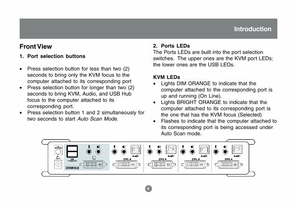
Front View1. Port selection buttons
• Press selection button for less than two (2)seconds to bring only the KVM focus to thecomputer attached to its corresponding port
• Press selection button for longer than two (2)seconds to bring KVM, Audio, and USB Hubfocus to the computer attached to itscorresponding port.
• Press selection button 1 and 2 simultaneously fortwo seconds to start Auto Scan Mode.
2. Ports LEDsThe Ports LEDs are built into the port selectionswitches. The upper ones are the KVM port LEDs;the lower ones are the USB LEDs.
KVM LEDs• Lights DIM ORANGE to indicate that the
computer attached to the corresponding port isup and running (On Line).
• Lights BRIGHT ORANGE to indicate that thecomputer attached to its corresponding port isthe one that has the KVM focus (Selected)
• Flashes to indicate that the computer attached toits corresponding port is being accessed underAuto Scan mode.
6
Introduction
USB LED• Lights GREEN to indicate that the computer
attached to its corresponding port is the onethat has access to the USB Peripherals.
3. USB Console portsYour USB keyboard and USB mouse plug in here.
7
Introduction
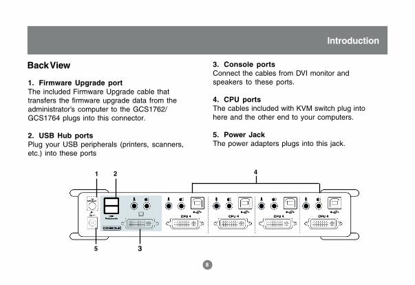
Back View
1. Firmware Upgrade portThe included Firmware Upgrade cable thattransfers the firmware upgrade data from theadministrator’s computer to the GCS1762/GCS1764 plugs into this connector.
2. USB Hub portsPlug your USB peripherals (printers, scanners,etc.) into these ports
3. Console portsConnect the cables from DVI monitor andspeakers to these ports.
4. CPU portsThe cables included with KVM switch plug intohere and the other end to your computers.
5. Power JackThe power adapters plugs into this jack.
1 2
3
4
5
8
Introduction
USB KVM Cable
9
Introduction
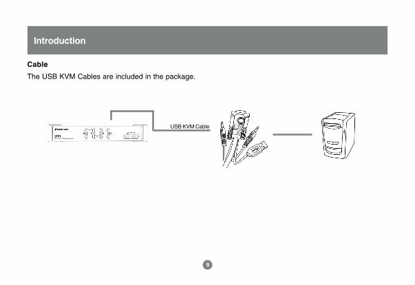
Cable
The USB KVM Cables are included in the package.
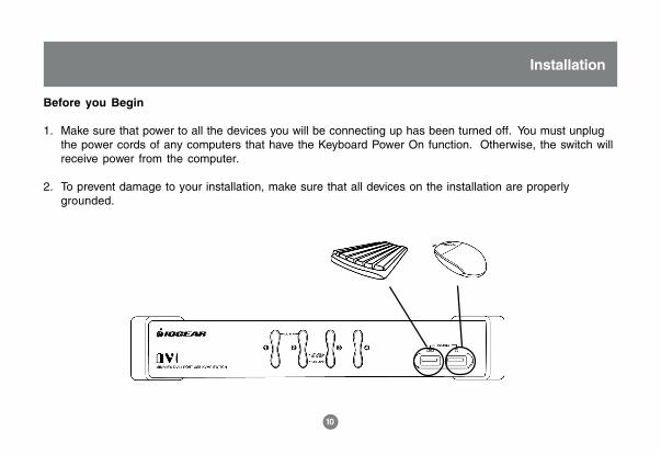
Before you Begin
1. Make sure that power to all the devices you will be connecting up has been turned off. You must unplugthe power cords of any computers that have the Keyboard Power On function. Otherwise, the switch willreceive power from the computer.
2. To prevent damage to your installation, make sure that all devices on the installation are properlygrounded.
10
Installation
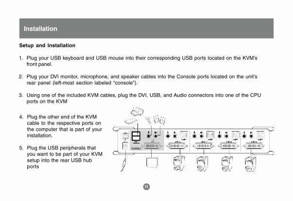
1. Plug your USB keyboard and USB mouse into their corresponding USB ports located on the KVM’sfront panel.
2. Plug your DVI monitor, microphone, and speaker cables into the Console ports located on the unit’srear panel (left-most section labeled “console”).
3. Using one of the included KVM cables, plug the DVI, USB, and Audio connectors into one of the CPUports on the KVM
4. Plug the other end of the KVMcable to the respective ports onthe computer that is part of yourinstallation.
5. Plug the USB peripherals thatyou want to be part of your KVMsetup into the rear USB hubports
11
Installation
Setup and Installation
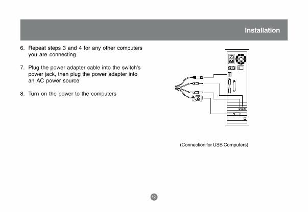
6. Repeat steps 3 and 4 for any other computersyou are connecting
7. Plug the power adapter cable into the switch’spower jack, then plug the power adapter intoan AC power source
8. Turn on the power to the computers
12
Installation
(Connection for USB Computers)
Hot Plugging
The GCS1762/GCS1764 supports USB hot plugging – components can be removed and added back intothe installation by unplugging their cables from the USB hub ports without the need to shut the unit down.
Powering Off and Restarting
If it becomes necessary to Power Off the KVM unit, before starting it back up you must do the following:
1. Shut down all the computers that are attached to the switch.2. Unplug power adapter cable from the switch3. Wait 10 seconds, then plug the switch’s power adapter cable back in.4. After the switch is up, Power On the computers.
NOTE: If the KVM switch has become unresponsive or shows erratic behavior, it is highly suggested that you unplug allcables from the KVM (all KVM cables and power cable) and leave the unit disconnected for 30 minutes. After this, plug all theKVM cables back and power ON the unit.
13
Basic Operation
Port ID Numbering
Each CPU port on the GCS1762/GCS1764 switch is assigned a port number (1 or 2 for GCS1762; 1 to 4 forGCS1764). The port numbers are marked on the rear panel of the switch.
The Port ID of a computer is derived from the CPU port number it is connected to. For example, a computerconnected to CPU port 2 has a Port ID of 2.
The Port ID is used to specify which computer gets the KVM USB peripheral, and audio focus with theHotkey port selection method.
Port SwitchingThere are two ways to access the computers in your KVM setup:· Manual switching – pressing the push-buttons on the unit’s front panel· Hotkey switching – entering commands from the keyboard
14
Basic Operation

Manual Switching
1. Press and release a port selection switch to bring the KVM focus to the computer attached to itscorresponding port. The USB and Audio focus does not change; they stay on the port that they’re alreadyon.
2. Press and hold a port selection switch for more than 2 seconds to bring the KVM, USB, and Audio focusto the computer attached to its corresponding port
3. Press and hold port selection switches 1 and 2 for more than two seconds to start Auto Scan Mode. Tip:To stop Auto Scan mode, simply press any of the port selection switches on the KVM.
15
Hotkey Operation
Hotkey Operation
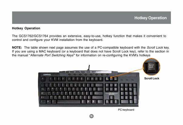
The GCS1762/GCS1764 provides an extensive, easy-to-use, hotkey function that makes it convenient tocontrol and configure your KVM installation from the keyboard.
NOTE: The table shown next page assumes the use of a PC-compatible keyboard with the Scroll Lock key.If you are using a MAC keyboard (or a keyboard that does not have Scroll Lock key), refer to the section inthe manual “Alternate Port Switching Keys” for information on re-configuring the KVM’s hotkeys
PC keyboard
Scroll Lock
16
Hotkey Operation
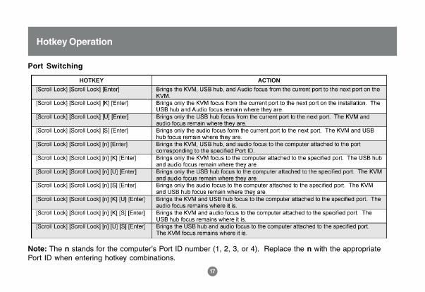
Port Switching
t
17
Hotkey Operation
Note: The n stands for the computer’s Port ID number (1, 2, 3, or 4). Replace the n with the appropriatePort ID when entering hotkey combinations.
18
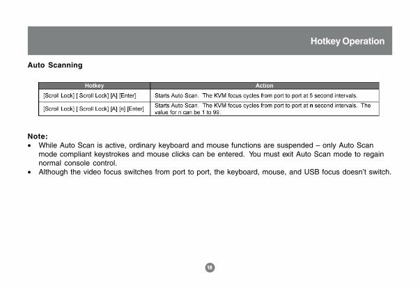
OSD OperationAuto Scanning
Hotkey Operation
Note:• While Auto Scan is active, ordinary keyboard and mouse functions are suspended – only Auto Scan
mode compliant keystrokes and mouse clicks can be entered. You must exit Auto Scan mode to regainnormal console control.
• Although the video focus switches from port to port, the keyboard, mouse, and USB focus doesn’t switch.

19
Hotkey Operation
Hotkey Setting Mode
Invoking HSMFor all Hotkey operations, you must use the number keypad on the right side of your keyboard.
To Invoke HSM (PC-Compatible keyboard):
1. Press and hold the Num Lock key2. Press and release the Minus key
PC keyboard
3. Release the Num Lock key within one half second after releasing Minus key;otherwise the KVM will not go into Hotkey mode.
Num Lock
Minus
20
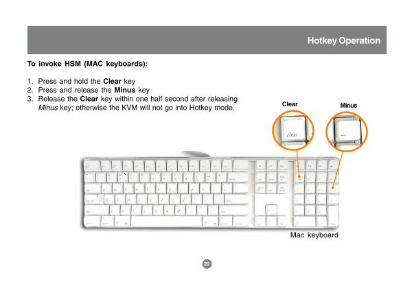
To invoke HSM (MAC keyboards):
1. Press and hold the Clear key2. Press and release the Minus key3. Release the Clear key within one half second after releasing
Minus key; otherwise the KVM will not go into Hotkey mode.
Mac keyboard
Hotkey Operation
Clear Minus
21
Hotkey Operation
Note:• If using the Num Lock and Minus key to invoke Hotkey function is not optimal for your setup, refer to the
next page to change the hotkey invocation keys.
When HSM is active, the Caps Lock and Scroll Lock LEDs flash in succession to indicate that HSM is ineffect. They stop flashing and revert to normal status when you exit HSM.
Ordinary keyboard and mouse functions are suspended – only Hotkey compliant keystrokes and mouseclicks can be input.
At the conclusion of some hotkey operations, you automatically exit Hotkey mode. With some operations,you must exit manually by pressing the Esc or Spacebar on your keyboard.
Alternate HSM Invocation Keys
In case the default HSM invocation keys (Num Lock and Minus) are not optimal in your setup, you maychange them to Ctrl and F12, respectively.
To switch to an alternate HSM invocation, do the following:
1. Invoke HSM (see page 19)2. Press and release H3. This will change the HSM invocation key to Ctrl and F12 (instead of Num Lock and Minus).
Note: This procedure is a toggle between the two methods. To revert back to the original HSM invocationkeys, repeat the above procedure again.
22
Hotkey Operation
23
Hotkey Operation
Alternate Port Switching Keys
The port switching activation keys can be changed from tapping Scroll Lock key twice ([Scroll Lock] [ScrollLock]) to tapping Ctrl key twice ([Ctrl] [Ctrl]).
If you have a MAC keyboard (or your keyboard does not have Scroll Lock), you can change the portswitching activation keys by doing the following:
1. Invoke HSM (see page 19)2. Press and release T
Now you can tap [Ctrl], [Ctrl] to switch between ports on your KVM. Please note that any hotkey operationsin the manual that use Scroll Lock, will now work with the new [Ctrl][Ctrl] port switching key.Note: This procedure is a toggle between the two methods. To revert back to the original port switchingkeys, repeat the above procedure.
24
Hotkey Operation
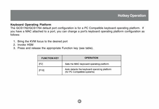
Keyboard Operating PlatformThe GCS1762/GCS1764 default port configuration is for a PC Compatible keyboard operating platform. Ifyou have a MAC attached to a port, you can change a port’s keyboard operating platform configuration asfollows:
1. Bring the KVM focus to the desired port2. Invoke HSM3. Press and release the appropriate Function key (see table).
25
Hotkey Operation
List Hotkey Settings
To see a list of the current hotkey settings, do the following:1. Invoke HSM2. Open a text editor (such as Notepad or Word)3. Press F4 on your keyboard to ‘paste’ this information
USB ResetIf the USB loses focus and needs to be reset, do the following:1. Invoke HSM2. Press and release F5 function key
Hotkey Beeper ControlThe beep sound the KVM makes when switching can be Toggled ON and OFF by doing the following:1. Invoke HSM2. Press and release B
Disable Port Switching KeysTo disable the port switching keys (Scroll Lock or Ctrl), please do the following:1. Invoke HSM2. Press [X] [Enter]
26
Hotkey Operation
Note: This procedure is a toggle. To re-enable the keys, repeat the procedure above.
Firmware Upgrade ModeTo set the GCS1762/GCS1764 in firmware upgrade mode:1. Invoke HSM2. Key in: upgrade3. Press [Enter]
Note: The front panel LEDs will flash to indicate that the KVM is in firmware upgrade mode. To exit firmwareupgrade mode, you must power off the switch.
Restore Default Settings
To reset the GCS1762/GCS1764 to its factory default settings, do the following:1. Invoke HSM2. Press [R] [Enter]
All hotkey settings return to factory default.
27
Hotkey Operation
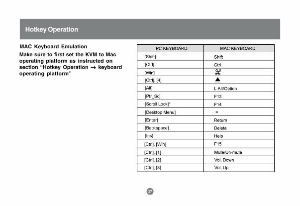
MAC Keyboard Emulation
Make sure to first set the KVM to Macoperating platform as instructed onsection “Hotkey Operation →→→→→ keyboardoperating platform”
28
Hotkey Operation
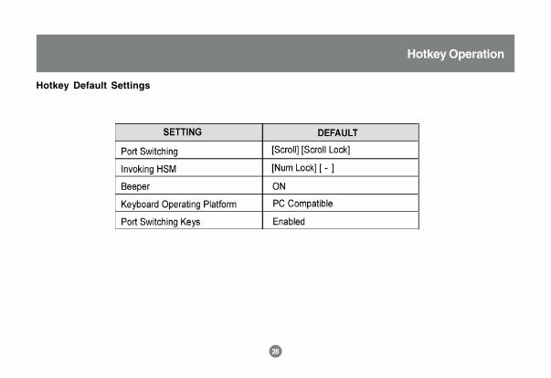
Hotkey Default Settings
29
The Windows-based Firmware Upgrade Utility (FWUpgrade.exe) provides a smooth, automated process forupgrading the KVM switch’s firmware. To run the firmware, you will need to use a windows based PC with anavailable serial port.
The Utility comes as part of a Firmware Upgrade Package that is specific for each device. New firmwareupgrade packages are posted on our web site as new firmware revisions become available. Check the website regularly to find the latest packages and information relating to them:
http://www.iogear.com
Before You Begin
To prepare for the firmware upgrade, do the following:
From a computer that is not part of your KVM installation, go to the IOGEAR support site and selectthe product part number (GCS1762 or GCS1764) to get a list of available Firmware UpgradePackages.
Choose the Firmware Upgrade Package you want to install (usually the most recent), and downloadit to your computer.
Use the Firmware Upgrade Cable provided with this unit, to connect to a serial port on yourcomputer to the Firmware Upgrade Port of your switch.
1.
2.
3.
The Firmware Upgrade Utility
30
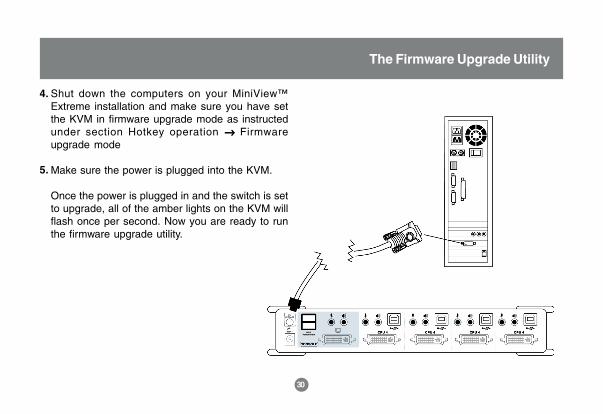
Shut down the computers on your MiniView™Extreme installation and make sure you have setthe KVM in firmware upgrade mode as instructedunder section Hotkey operation → → → → → Firmwareupgrade mode
Make sure the power is plugged into the KVM.
Once the power is plugged in and the switch is setto upgrade, all of the amber lights on the KVM willflash once per second. Now you are ready to runthe firmware upgrade utility.
4.
5.
The Firmware Upgrade Utility
31
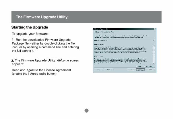
To upgrade your firmware:
Run the downloaded Firmware UpgradePackage file - either by double-clicking the fileicon, or by opening a command line and enteringthe full path to it.
The Firmware Upgrade Utility Welcome screenappears:
Read and Agree to the License Agreement(enable the I Agree radio button).
1.
2.
Starting the Upgrade
The Firmware Upgrade Utility
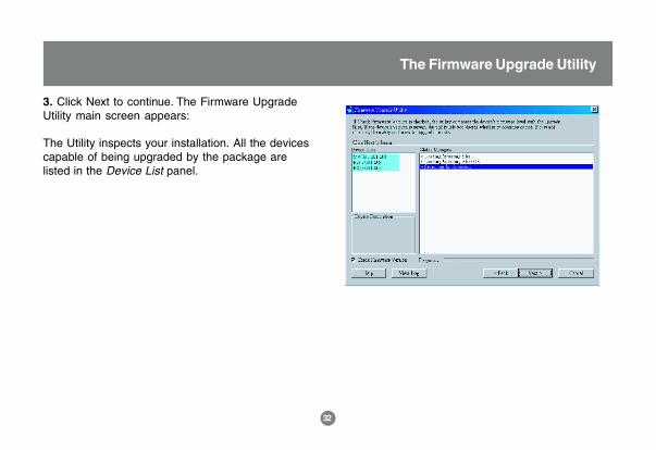
3. Click Next to continue. The Firmware UpgradeUtility main screen appears:
The Utility inspects your installation. All the devicescapable of being upgraded by the package arelisted in the Device List panel.
32
The Firmware Upgrade Utility
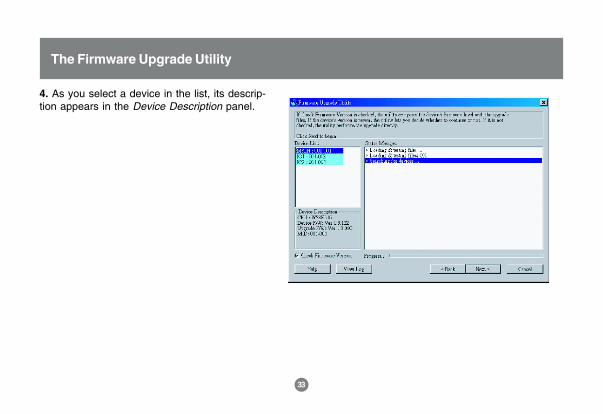
4. As you select a device in the list, its descrip-tion appears in the Device Description panel.
33
The Firmware Upgrade Utility
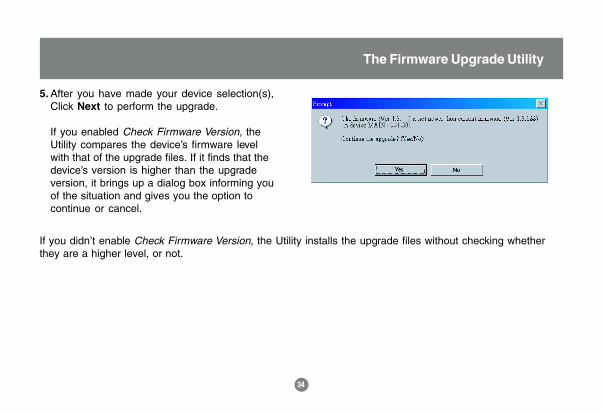
After you have made your device selection(s),Click Next to perform the upgrade.
If you enabled Check Firmware Version, theUtility compares the device’s firmware levelwith that of the upgrade files. If it finds that thedevice’s version is higher than the upgradeversion, it brings up a dialog box informing youof the situation and gives you the option tocontinue or cancel.
5.
If you didn’t enable Check Firmware Version, the Utility installs the upgrade files without checking whetherthey are a higher level, or not.
34
The Firmware Upgrade Utility
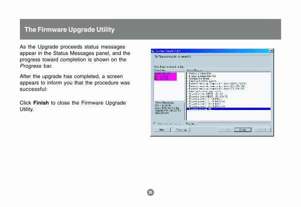
As the Upgrade proceeds status messagesappear in the Status Messages panel, and theprogress toward completion is shown on theProgress bar.
After the upgrade has completed, a screenappears to inform you that the procedure wassuccessful:
Click Finish to close the Firmware UpgradeUtility.
The Firmware Upgrade Utility
35
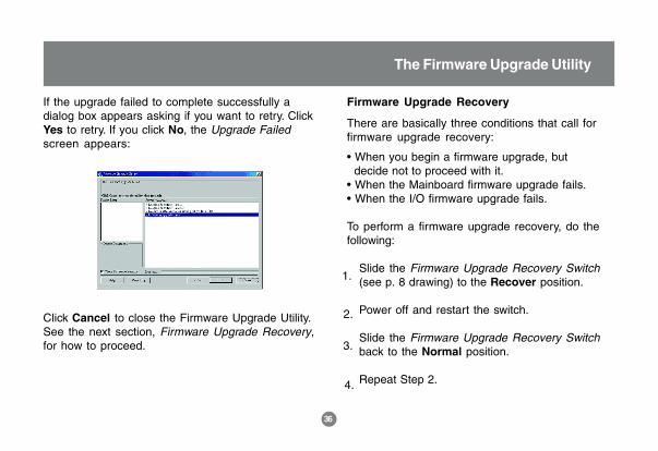
If the upgrade failed to complete successfully adialog box appears asking if you want to retry. ClickYes to retry. If you click No, the Upgrade Failedscreen appears:
Click Cancel to close the Firmware Upgrade Utility.See the next section, Firmware Upgrade Recovery,for how to proceed.
Firmware Upgrade Recovery
There are basically three conditions that call forfirmware upgrade recovery:
• When you begin a firmware upgrade, but decide not to proceed with it.• When the Mainboard firmware upgrade fails.• When the I/O firmware upgrade fails.
To perform a firmware upgrade recovery, do thefollowing:
Slide the Firmware Upgrade Recovery Switch(see p. 8 drawing) to the Recover position.
Power off and restart the switch.
Slide the Firmware Upgrade Recovery Switchback to the Normal position.
Repeat Step 2.
1.
2.
3.
4.
The Firmware Upgrade Utility
36

Appendix
Troubleshooting
37
38
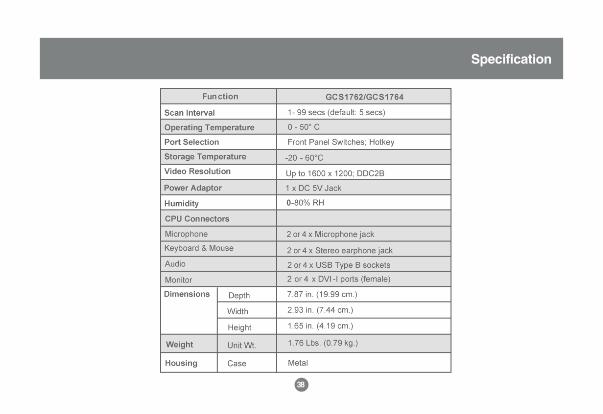
Specification
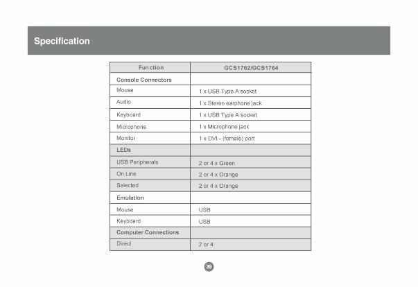
Specification
39

Technical Support
If you need technical support, please check out our IOGEAR Tech Info Library (T.I.L.) at www.iogear.com/support for the latest tips, tricks, and troubleshooting. The IOGEAR T.I.L. was designed to provide you withthe latest technical information about our products. Most of the answers to your questions can be foundhere, so please try it out before contacting technical support.
Technical support is available Monday through Friday from 8:00 am to 5:00 pm PST and can be reached at(949) 453-8782.
40
Radio & TV Interference Statement
WARNING!!! This equipment generates, uses and can radiate radio frequency energy and, if not installedand used in accordance with the instruction manual, may cause interference to radio communications. Thisequipment has been tested and found to comply with the limits for a Class B computing device pursuant toSubpart J of Part 15 of FCC Rules, which are designed to provide reasonable protection against suchinterference when operated in a commercial environment. Operation of this equipment in a residential area islikely to cause interference, in which case the user at his own expense will be required to take whatevermeasures may be required to correct the interference.
41
IN NO EVENT SHALL THE DIRECT VENDOR’S LIABILITY FOR DIRECT, INDIRECT, SPECIAL, INCIDEN-TAL OR CONSEQUENTIAL DAMAGES RESULTING FROM THE USE OF THE PRODUCT, DISK, OR ITSDOCUMENTATION EXCEED THE PRICE PAID FOR THE PRODUCT.
The direct vendor makes no warranty or representation, expressed, implied, or statutory with respect to thecontents or use of this documentation, and especially disclaims its quality, performance, merchantability, orfitness for any particular purpose.
The direct vendor also reserves the right to revise or update the device or documentation without obligationto notify any individual or entity of such revisions, or updates. For further inquires please contact your directvendor.
Limited Warranty
42

23 Hubble • Irvine, CA 92618 • (P) 949.453.8782 • (F) 949.453.8785 • www.iogear.com
Contact info.
®


