15
Minto Mine QML-0001 Underground Mine Development and Operations Plan Amendment Copper Keel Ramp March 2018 Prepared by: Minto Explorations Ltd.
Minto Mine QML-0001
Underground Mine Development and Operations Plan Amendment
Copper Keel Ramp March 2018
Prepared by:
Minto Explorations Ltd.
Minto Mine QML-0001 UMDOP Amendment – Copper Keel Ramp – March 2018
i
Table of Contents
1 Introduction ........................................................................................................................................................1 2 Operations Overview ..........................................................................................................................................1 3 Deposits and Ore Reserves .................................................................................................................................1 4 Mine Development and Design ..........................................................................................................................4
4.1 Ramp Development ....................................................................................................................................4 5 Mine Operation ..................................................................................................................................................4
5.1 Material Handling .......................................................................................................................................4 6 Geotechnical .......................................................................................................................................................5
6.1 Ground Support Requirements ..................................................................................................................5 6.2 Monitoring ..................................................................................................................................................6 6.3 Hydrogeological Assessment ......................................................................................................................6
7 Ventilation, Ancillary Infrastructure, and Dewatering .......................................................................................7 7.1 Ventilation ..................................................................................................................................................7 7.2 Compressed Air ..........................................................................................................................................9 7.3 Underground Electrical Power ................................................................................................................ 10 7.4 Water Supply ........................................................................................................................................... 10 7.5 Dewatering .............................................................................................................................................. 10 7.6 Communications ...................................................................................................................................... 10 7.7 Blasting Procedure and Infrastructure .................................................................................................... 10 7.8 Explosive Storage and Handling .............................................................................................................. 11
8 Conclusion ....................................................................................................................................................... 11
List of Figures
Figure 3-1: Plan view of underground development and ore zones. .........................................................................2
Figure 3-2: Section view through Copper Keel Ramp, showing Copper Keel West ore lenses. .................................3
Figure 7-1: Ventilation configuration for Copper Keel Ramp prior to Minto East raise commissioning. ...................7
Figure 7-2: Ventilation configuration for Copper Keel Ramp after Minto East raise commissioning. .......................8
List of Tables
Table 6-1: Ground Support Elements .........................................................................................................................5
Table 6-2: Minimum Ground Support for Development and Production Openings ..................................................5
Table 6-3: Summary of Ground Control Monitoring ..................................................................................................6
Table 7-1: Ventilation requirements for the Minto South Underground ..................................................................9
Minto Mine QML-0001 UMDOP Amendment – Copper Keel Ramp – March 2018
1
1 Introduction
This document amends the Underground Mine Development and Operations Plan (UMDOP) to include 310m of
ramp development toward the Copper Keel zone.
This ramp is to be developed in Q2 2018 to allow for in-fill diamond drilling of small satellite lenses northwest of
the main Copper Keel zone, and to serve as an access to the main Copper Keel zone.
The design of Copper Keel stopes, accesses, ventilation, escapeway, and other related infrastructure, will be
finalized in Q2 2018 and presented in a revision to the UMDOP.
2 Operations Overview
As of March 2018, production continues in the Area 2 zone.
Development continues in Minto East, but is limited to waste pending completion of an escapeway from that area.
An escapeway consisting of a 1.4m-diameter bored raise with a Safescape ladder tube system was installed in
December 2017 but is no longer operational due to ground instability. Installation of a replacement using the
same technique is currently in progress. Prior to raiseboring, the ground was stabilized by a grouting campaign,
and the upper portion of the completed raise will be shotcreted before a ladder tube is installed.
3 Deposits and Ore Reserves
The Copper Keel zone consists of a main lens, located approximately 450m southeast of the Minto East ramp, and
several small satellite lenses (Copper Keel West and Copper Keel North) located closer to the Minto East ramp.
Production will begin in the Main lens, while the small satellite lenses require additional diamond drilling,
geological modeling, and design work.
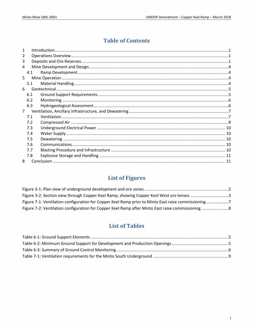
A preliminary design for Copper Keel is shown in Figure 3-1 on the following page. The design is not yet finalized
for the Copper Keel Main lens, and infrastructure such as the ventilation raise, escapeway, truck loadout, sump,
and electrical substation have not been included.
The West and North lenses are shown only as preliminary stope shapes; access ramps are omitted, as additional
diamond drilling will likely result in a significant redesign. These zones are located beneath the proposed ramp. A
section view through the ramp is shown in Figure 3-2.
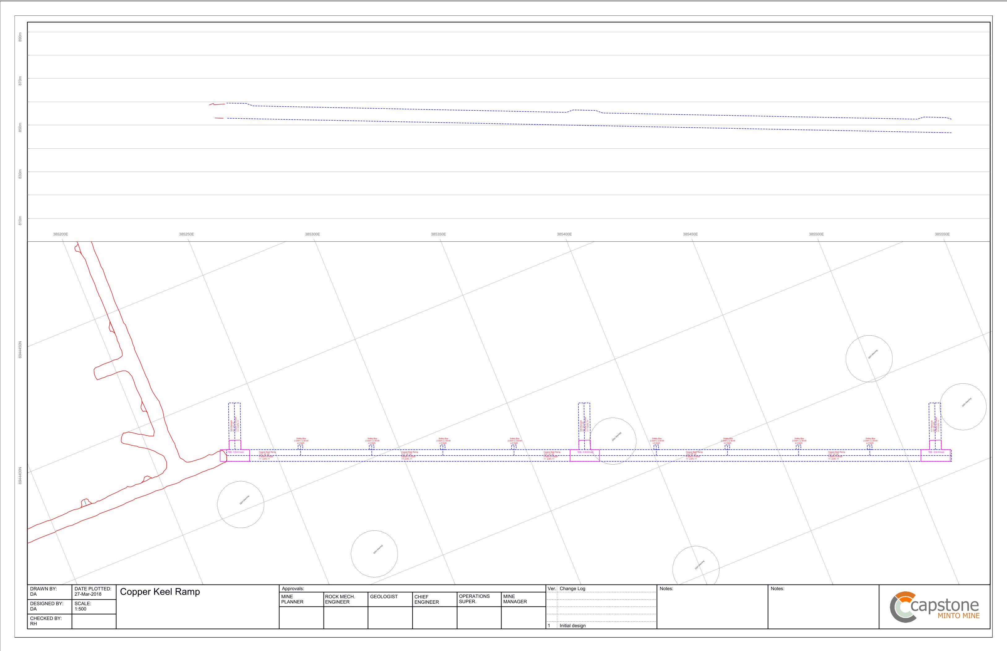
The scope of this document is limited to the 310m of ramp development shown in green in this figure. A block
plan for the ramp development is attached in Appendix 1.
No ore is expected from ramp development, as it does not pass through any known ore lenses.
Minto Mine QML-0001 UMDOP Amendment – Copper Keel Ramp – March 2018
2
Figure 3-1: Plan view of underground development and ore zones.

Minto Mine QML-0001 UMDOP Amendment – Copper Keel Ramp – March 2018
3
Figure 3-2: Section view through Copper Keel Ramp, showing Copper Keel West ore lenses.
Minto Mine QML-0001 UMDOP Amendment – Copper Keel Ramp – March 2018
4
4 Mine Development and Design
4.1 Ramp Development
The ramp is 5.0m wide and 5.5m high, consistent with the main ramp to the Area 2 with Minto East zones. It will
be used for all ore and waste haulage, personnel/equipment access, and services running to the Copper Keel zone.
Re-muck bays are developed every 150 m to improve the efficiency of the development cycle; they are designed
to hold two rounds of development muck. The re-muck bays have the same dimensions as the decline and are 20
m in length. Additional cutouts for drill bays, sumps, etc. are developed as required.
5 Mine Operation
5.1 Material Handling
A combination of 7- and 10-yard LHD units and 42 tonne trucks are used for haulage. The back height is increased
to 6.5m at remuck intersections to provide the height necessary for the LHD units to load trucks.
Waste rock from development headings is hauled to a surface stockpile adjacent to the portal. Development
rounds are assayed and the waste is moved to the appropriate waste dump as outlined in the Waste Rock and
Overburden Management Plan (WROMP). The protocols for segregation and placement of waste materials are
consistent with the protocols for surface mining.
Minto Mine QML-0001 UMDOP Amendment – Copper Keel Ramp – March 2018
5
6 Geotechnical
6.1 Ground Support Requirements
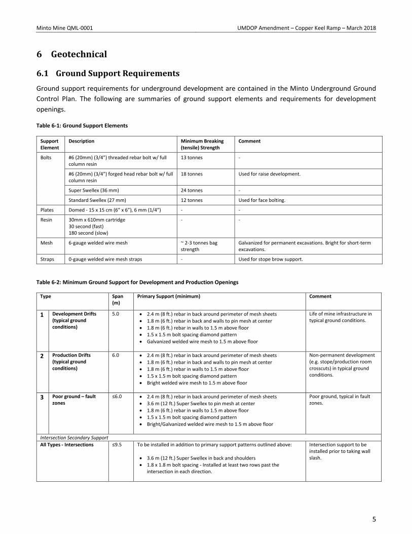
Ground support requirements for underground development are contained in the Minto Underground Ground
Control Plan. The following are summaries of ground support elements and requirements for development
openings.
Table 6-1: Ground Support Elements
Support Element
Description Minimum Breaking (tensile) Strength
Comment
Bolts #6 (20mm) (3/4”) threaded rebar bolt w/ full column resin
13 tonnes -
#6 (20mm) (3/4”) forged head rebar bolt w/ full column resin
18 tonnes Used for raise development.
Super Swellex (36 mm) 24 tonnes -
Standard Swellex (27 mm) 12 tonnes Used for face bolting.
Plates Domed - 15 x 15 cm (6” x 6”), 6 mm (1/4”) - -
Resin 30mm x 610mm cartridge 30 second (fast) 180 second (slow)
- -
Mesh 6-gauge welded wire mesh ~ 2-3 tonnes bag strength
Galvanized for permanent excavations. Bright for short-term excavations.
Straps 0-gauge welded wire mesh straps - Used for stope brow support.
Table 6-2: Minimum Ground Support for Development and Production Openings
Type Span (m)
Primary Support (minimum) Comment
1 Development Drifts (typical ground conditions)
5.0 2.4 m (8 ft.) rebar in back around perimeter of mesh sheets
1.8 m (6 ft.) rebar in back and walls to pin mesh at center
1.8 m (6 ft.) rebar in walls to 1.5 m above floor
1.5 x 1.5 m bolt spacing diamond pattern
Galvanized welded wire mesh to 1.5 m above floor
Life of mine infrastructure in typical ground conditions.
2 Production Drifts (typical ground conditions)
6.0 2.4 m (8 ft.) rebar in back around perimeter of mesh sheets
1.8 m (6 ft.) rebar in back and walls to pin mesh at center
1.8 m (6 ft.) rebar in walls to 1.5 m above floor
1.5 x 1.5 m bolt spacing diamond pattern
Bright welded wire mesh to 1.5 m above floor
Non-permanent development (e.g. stope/production room crosscuts) in typical ground conditions.
3 Poor ground – fault zones
≤6.0 2.4 m (8 ft.) rebar in back around perimeter of mesh sheets
3.6 m (12 ft.) Super Swellex to pin mesh at center
1.8 m (6 ft.) rebar in walls to 1.5 m above floor
1.5 x 1.5 m bolt spacing diamond pattern
Bright/Galvanized welded wire mesh to 1.5 m above floor
Poor ground, typical in fault zones.
Intersection Secondary Support
All Types - Intersections
≤9.5 To be installed in addition to primary support patterns outlined above:
3.6 m (12 ft.) Super Swellex in back and shoulders
1.8 x 1.8 m bolt spacing - Installed at least two rows past the intersection in each direction.
Intersection support to be installed prior to taking wall slash.
Minto Mine QML-0001 UMDOP Amendment – Copper Keel Ramp – March 2018
6
6.2 Monitoring
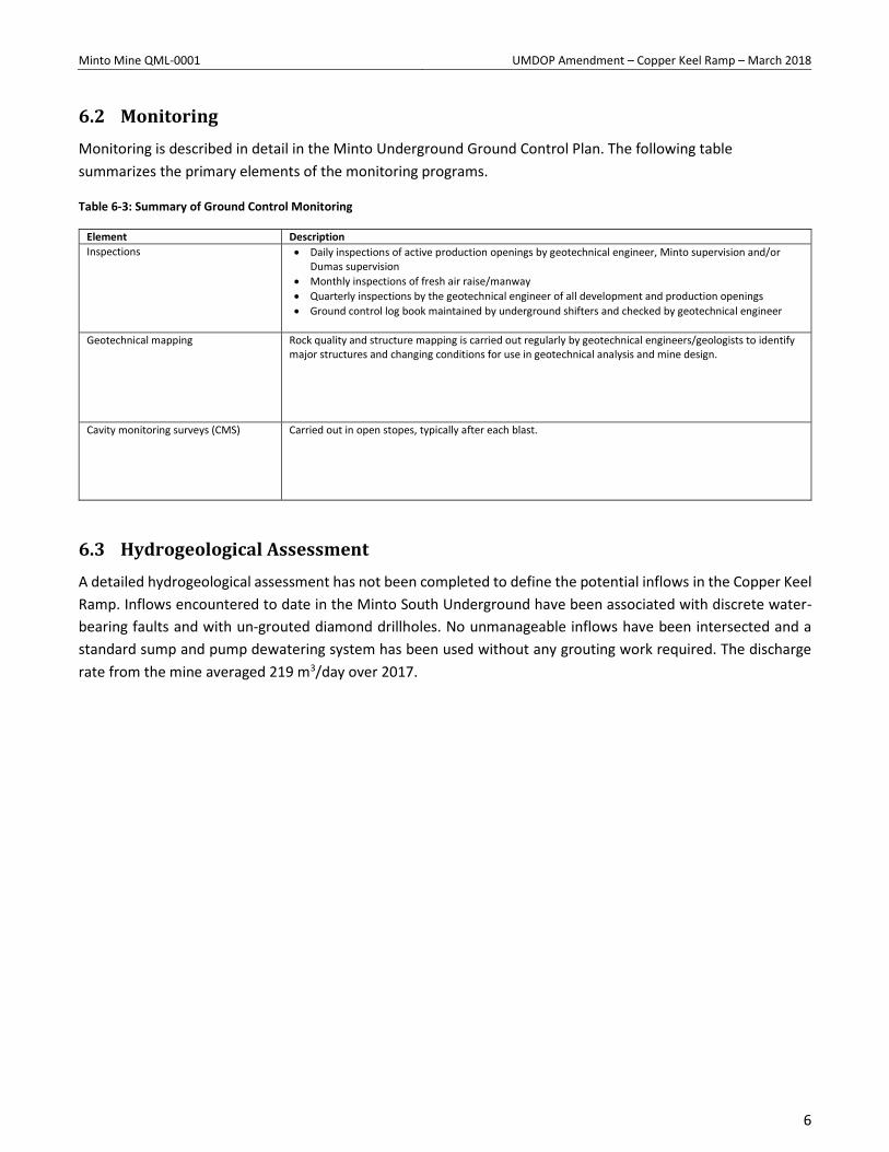
Monitoring is described in detail in the Minto Underground Ground Control Plan. The following table
summarizes the primary elements of the monitoring programs.
Table 6-3: Summary of Ground Control Monitoring
Element Description
Inspections Daily inspections of active production openings by geotechnical engineer, Minto supervision and/or Dumas supervision
Monthly inspections of fresh air raise/manway
Quarterly inspections by the geotechnical engineer of all development and production openings
Ground control log book maintained by underground shifters and checked by geotechnical engineer
Geotechnical mapping Rock quality and structure mapping is carried out regularly by geotechnical engineers/geologists to identify major structures and changing conditions for use in geotechnical analysis and mine design.
Cavity monitoring surveys (CMS) Carried out in open stopes, typically after each blast.
6.3 Hydrogeological Assessment
A detailed hydrogeological assessment has not been completed to define the potential inflows in the Copper Keel
Ramp. Inflows encountered to date in the Minto South Underground have been associated with discrete water-
bearing faults and with un-grouted diamond drillholes. No unmanageable inflows have been intersected and a
standard sump and pump dewatering system has been used without any grouting work required. The discharge
rate from the mine averaged 219 m3/day over 2017.
Minto Mine QML-0001 UMDOP Amendment – Copper Keel Ramp – March 2018
7
7 Ventilation, Ancillary Infrastructure, and Dewatering
7.1 Ventilation
The Copper Keel Ramp will be ventilated by a single 48” steel duct with in-line 150 hp 48” electric fans. This
approach has been used throughout the life of the mine to ventilate development headings and will be carried
forward unchanged. A second duct will be hung in parallel with the first in preparation for more intensive
development in the Copper Keel zone, but the inline booster fans in the second duct will not be powered up until
development begins in multiple headings.
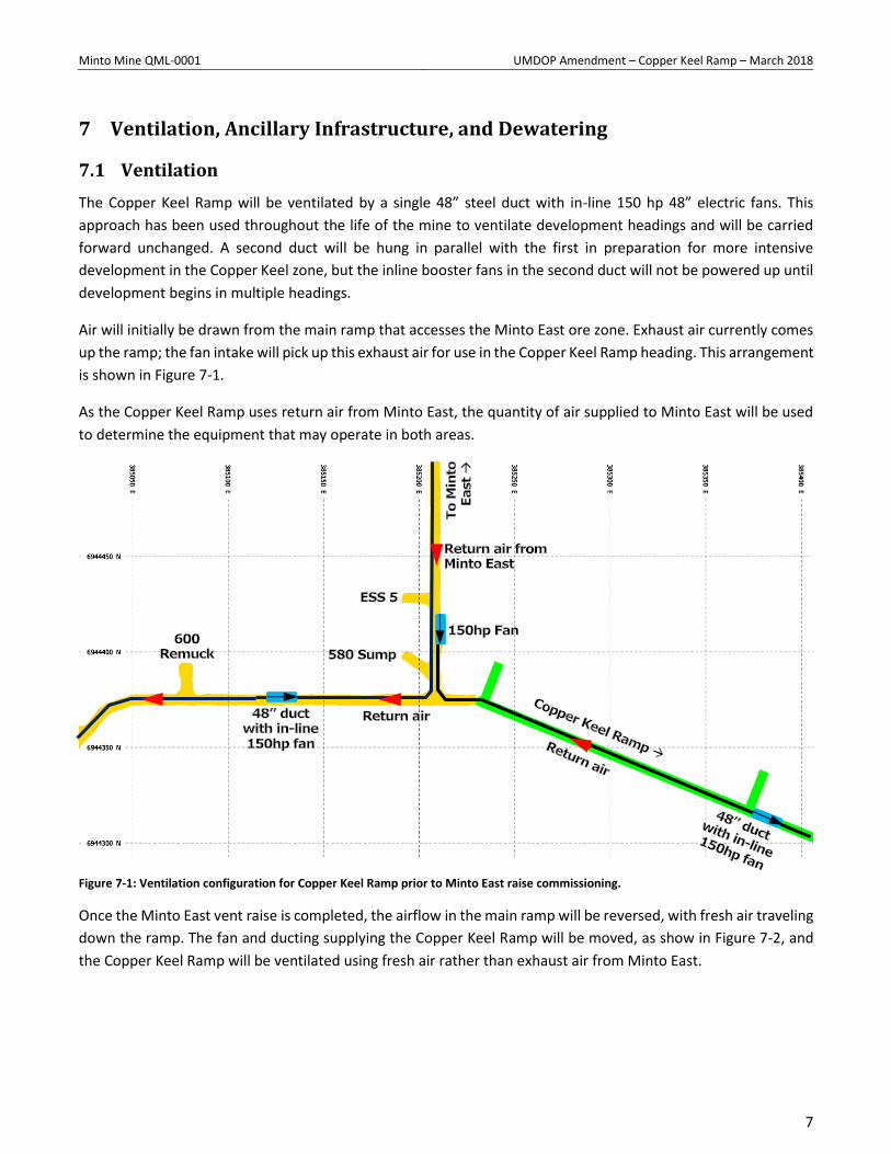
Air will initially be drawn from the main ramp that accesses the Minto East ore zone. Exhaust air currently comes
up the ramp; the fan intake will pick up this exhaust air for use in the Copper Keel Ramp heading. This arrangement
is shown in Figure 7-1.
As the Copper Keel Ramp uses return air from Minto East, the quantity of air supplied to Minto East will be used
to determine the equipment that may operate in both areas.
Figure 7-1: Ventilation configuration for Copper Keel Ramp prior to Minto East raise commissioning.
Once the Minto East vent raise is completed, the airflow in the main ramp will be reversed, with fresh air traveling
down the ramp. The fan and ducting supplying the Copper Keel Ramp will be moved, as show in Figure 7-2, and
the Copper Keel Ramp will be ventilated using fresh air rather than exhaust air from Minto East.
Minto Mine QML-0001 UMDOP Amendment – Copper Keel Ramp – March 2018
8
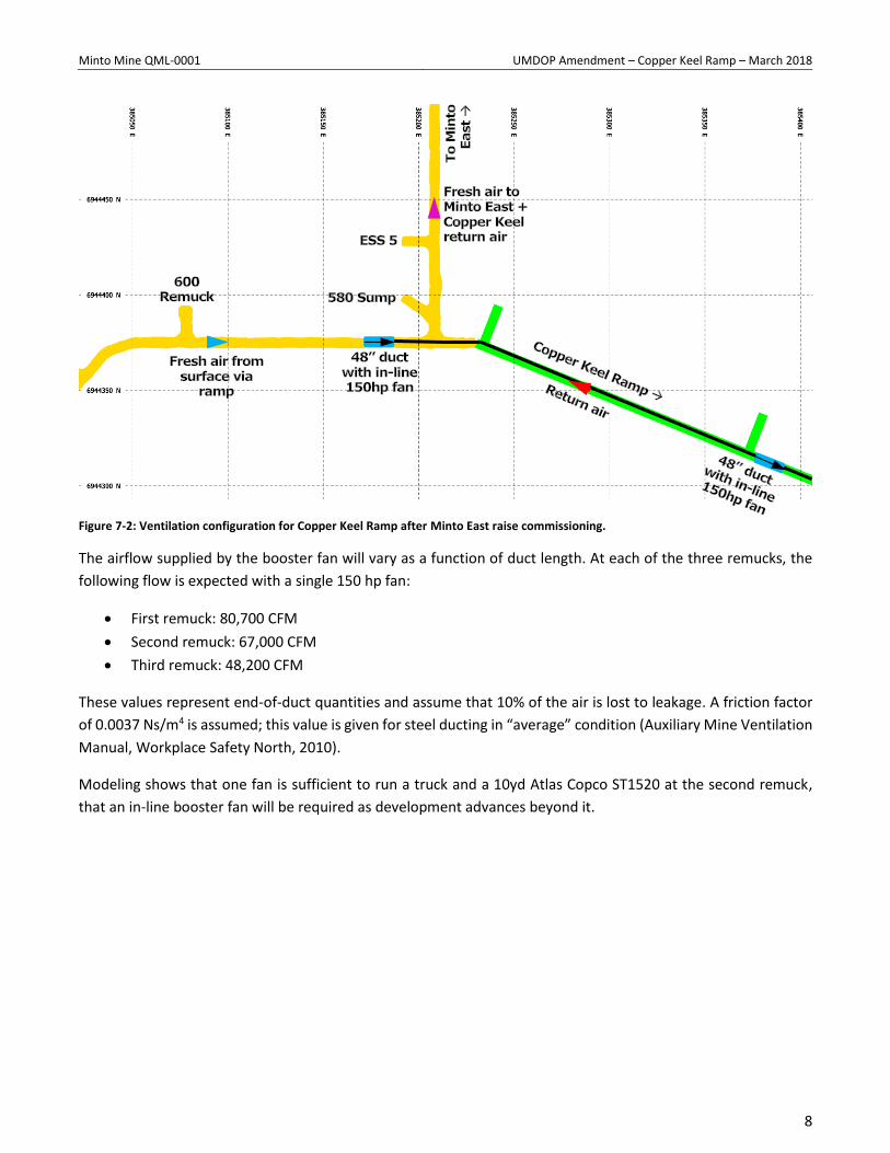
Figure 7-2: Ventilation configuration for Copper Keel Ramp after Minto East raise commissioning.
The airflow supplied by the booster fan will vary as a function of duct length. At each of the three remucks, the
following flow is expected with a single 150 hp fan:
First remuck: 80,700 CFM
Second remuck: 67,000 CFM
Third remuck: 48,200 CFM
These values represent end-of-duct quantities and assume that 10% of the air is lost to leakage. A friction factor
of 0.0037 Ns/m4 is assumed; this value is given for steel ducting in “average” condition (Auxiliary Mine Ventilation
Manual, Workplace Safety North, 2010).
Modeling shows that one fan is sufficient to run a truck and a 10yd Atlas Copco ST1520 at the second remuck,
that an in-line booster fan will be required as development advances beyond it.
Minto Mine QML-0001 UMDOP Amendment – Copper Keel Ramp – March 2018
9
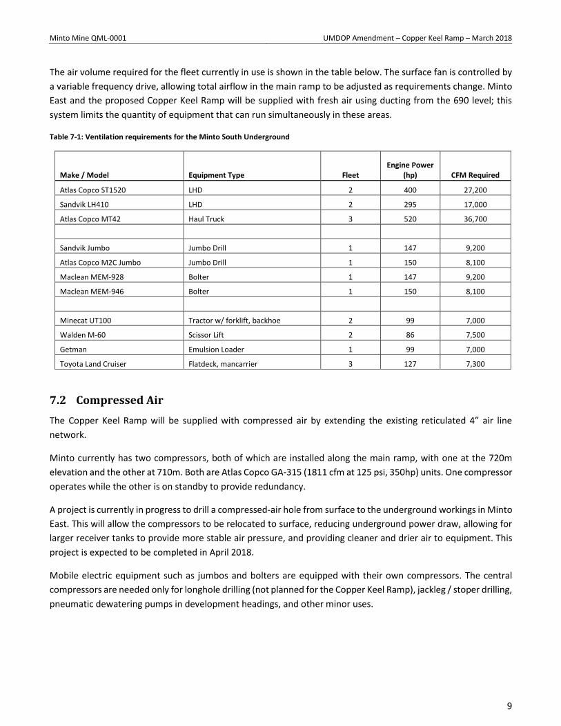
The air volume required for the fleet currently in use is shown in the table below. The surface fan is controlled by
a variable frequency drive, allowing total airflow in the main ramp to be adjusted as requirements change. Minto
East and the proposed Copper Keel Ramp will be supplied with fresh air using ducting from the 690 level; this
system limits the quantity of equipment that can run simultaneously in these areas.
Table 7-1: Ventilation requirements for the Minto South Underground
Make / Model Equipment Type Fleet Engine Power
(hp) CFM Required
Atlas Copco ST1520 LHD 2 400 27,200
Sandvik LH410 LHD 2 295 17,000
Atlas Copco MT42 Haul Truck 3 520 36,700
Sandvik Jumbo Jumbo Drill 1 147 9,200
Atlas Copco M2C Jumbo Jumbo Drill 1 150 8,100
Maclean MEM-928 Bolter 1 147 9,200
Maclean MEM-946 Bolter 1 150 8,100
Minecat UT100 Tractor w/ forklift, backhoe 2 99 7,000
Walden M-60 Scissor Lift 2 86 7,500
Getman Emulsion Loader 1 99 7,000
Toyota Land Cruiser Flatdeck, mancarrier 3 127 7,300
7.2 Compressed Air
The Copper Keel Ramp will be supplied with compressed air by extending the existing reticulated 4” air line
network.
Minto currently has two compressors, both of which are installed along the main ramp, with one at the 720m
elevation and the other at 710m. Both are Atlas Copco GA-315 (1811 cfm at 125 psi, 350hp) units. One compressor
operates while the other is on standby to provide redundancy.
A project is currently in progress to drill a compressed-air hole from surface to the underground workings in Minto
East. This will allow the compressors to be relocated to surface, reducing underground power draw, allowing for
larger receiver tanks to provide more stable air pressure, and providing cleaner and drier air to equipment. This
project is expected to be completed in April 2018.
Mobile electric equipment such as jumbos and bolters are equipped with their own compressors. The central
compressors are needed only for longhole drilling (not planned for the Copper Keel Ramp), jackleg / stoper drilling,
pneumatic dewatering pumps in development headings, and other minor uses.
Minto Mine QML-0001 UMDOP Amendment – Copper Keel Ramp – March 2018
10
7.3 Underground Electrical Power
The Copper Keel Ramp is supplied with 600V power for fans, pumps, and mobile equipment by Electrical
Substation 5 (ESS 5), located 50m down-ramp of the Minto East / Copper Keel intersection. A 1000 kVA air-cooled
substation is installed at this location, along with starter panels for fans, pumps, and mobile equipment.
This substation currently supplies power to the Minto East zone, and has adequate capacity for the loads expected
during development of the Copper Keel Ramp. A new 1000 kVA electrical substation will be installed closer to
Minto East, freeing up capacity on ESS 5 for further mining of Copper Keel.
Mobile equipment will be powered by 2/0 G-GC cable run from an existing starter panel to the working face.
7.4 Water Supply
The Copper Keel Ramp will be supplied with water for drilling and dust suppression by extending the existing
reticulated 4” water line network.
7.5 Dewatering
The ramp is developed at a -2.0% grade; water will be collected at the face and transferred to the nearest sump
in the Minto East ramp.
Water is currently transferred to surface via a series of eight sumps with submersible pumps. This system will be
replaced by a new pump station installed in Minto East, equipped with redundant high-pressure pumps that will
transfer water directly to surface via a new pipeline installed in a borehole.
The borehole will break through to surface adjacent to the Main Pit Tailings Management Facility (MPTMF), which
will receive the underground water stream.
7.6 Communications
In February 2018, a mine-wide leaky feeder radio system was installed. This provides three channels: one for ramp
traffic, one spare, and one emergency channel. The latter is repeated on surface, providing a unified site-wide
emergency channel.
Refuge stations will continue to be equipped with telephones connected to the mine’s internal communications
network via a fiber optic network that runs throughout the Minto South Underground.
An analog emergency communication system (Femco phone) is also installed inside and outside the refuge
stations, the base of the fresh air raise at 760 level, the surface muster station adjacent to the portal, and the
Dumas shop on surface.
7.7 Blasting Procedure and Infrastructure
The mine’s electric central blasting system will be extended into the Copper Keel Ramp. This typically fires a single
electric blasting cap, which is used to initiate the network of non-electric caps that time and fire each hole in a
development blast. The mine is completely cleared of personnel for both production and development blasting.
Minto Mine QML-0001 UMDOP Amendment – Copper Keel Ramp – March 2018
11
7.8 Explosive Storage and Handling
Emulsion will be used for development blasting. A bulk emulsion product, Dyno Titan RU, is delivered via a
dedicated mobile loading unit mounted on a mine utility vehicle. A perimeter blasting product (Dynosplit D) is
used to reduce overbreak in the back, and Dyno AP (a cartridge emulsion) is used in wet lifter holes.
There will be no changes to magazine locations or licensed quantities.
8 Conclusion
This document presents a plan to mine 310m of ramp development toward the Copper Keel zone. This will allow
for diamond drilling to better define the West and North lenses and provide access to the Main lens.
Copper Keel design work will continue and, when complete, will be presented in a new Underground Mine
Development and Operations Plan.

Appendix 1 – Copper Keel Ramp Block Plan
385200E 385250E 385300E 385350E 385400E 385450E 385500E 385550E
6944
400N
6944
450N
SCALE:
DATE PLOTTED:
CHECKED BY:
DESIGNED BY:
DRAWN BY:
GEOLOGIST
Approvals:
MINTO MINEcapstone
Notes: Notes:Change LogVer.Copper Keel RampDA
DA
RH
27-Mar-2018
1 Initial design
TDB - 6.5mH backTDB - 6.5mH back TDB - 6.5mH back
DDH Warn
ing
DDH Warn
ing
DDH Warn
ing
DDH Warn
ing
DDH Warn
ing
DDH Warn
ing
DDH Warn
ing
DDH Warn
ing
DDH Warn
ing
DDH Warn
ing
DDH Warn
ing
DDH Warn
ing
810m
830m
850m
870m
890m
1:500
MINEMANAGER
OPERATIONSSUPER.
CHIEFENGINEER
ROCK MECH.ENGINEER
MINEPLANNER
Safety Bay2.0mH x 2.0mW x 2.0mD
Safety Bay2.0mH x 2.0mW x 2.0mD
Safety Bay2.0mH x 2.0mW x 2.0mD
Safety Bay2.0mH x 2.0mW x 2.0mD
Safety Bay2.0mH x 2.0mW x 2.0mD
Safety Bay2.0mH x 2.0mW x 2.0mD
Safety Bay2.0mH x 2.0mW x 2.0mD
Safety Bay2.0mH x 2.0mW x 2.0mD
Copper Keel Ramp112° 12' 12"5.5mH x 5.0mW>> -2.0% >>
Copper Keel Ramp112° 12' 12"5.5mH x 5.0mW>> -2.0% >>
Copper Keel Ramp112° 12' 12"5.5mH x 5.0mW>> -2.0% >>
Copper Keel Ramp112° 12' 12"5.5mH x 5.0mW>> -2.0% >>
583
Rem
uck
22°
12' 1
2"5.
5mH
x 5
.0m
W>>
+2.
0% >
>
580
Rem
uck
22°
12' 1
2"5.
5mH
x 5
.0m
W>>
+2.
0% >
>
577
Rem
uck
22°
12' 1
2"5.
5mH
x 5
.0m
W>>
+2.
0% >
>
Copper Keel Ramp112° 12' 12"5.5mH x 5.0mW>> -2.0% >>


