Important! This product is suitable for mains fed cold water only. Installation Guide Mira Advance ATL ADJUSTABLE TEMPERATURE LIMIT THERMOSTATIC 9.0 and 9.8 kW For SPARES, ADVICE or REPAIRS Please call us on 0844 571 5000 (UK Only)
Transcript
1
Important! This product is suitable for mains fed cold water only.
Installation Guide
Mira Advance ATLADJUSTABLE TEMPERATURE LIMIT THERMOSTATIC
Guarantee ............................................................................................4Patents and Design Registration ..........................................................5
Important Safety Information .................................................................5Warning ................................................................................................5Caution .................................................................................................6
Standards and Approvals .....................................................................8Dimensions ...........................................................................................9
Installation .............................................................................................13Priming the Shower ............................................................................14
Mira Advance Shower Models for use with the Instantmatch by Whale® Digital Pump ................................................16
Electrical Schematic Diagram (Drain Pump) ......................................17Instantmatch by Whale® Digital Pump ................................................18
Wireless Installation ...........................................................................19 Wireless Signal Schematic Diagram ..........................................19 Drain Pump Registration ............................................................20 Drain Pump Test .........................................................................20 Registration or Test Failure ........................................................21Basic Post Installation Checks ...........................................................22
Commissioning .....................................................................................23Set Maximum Temperature and Commissioning Cycle ......................23Commissioning Failures .....................................................................24BEAB Care .........................................................................................25Memory Model ....................................................................................25
If you experience any difficulty with the installation or operation of your new Electric Shower, then please refer to 'Fault Diagnosis', before contacting Mira Showers. Our contact details can be found on the back cover of this guide.
BEAB Care In-Service Tests .................................................................32Maintenance ...........................................................................................35Spare Parts and Accessories ...............................................................36Wiring Diagram ......................................................................................38Customer Service .................................................................. Back Cover
4
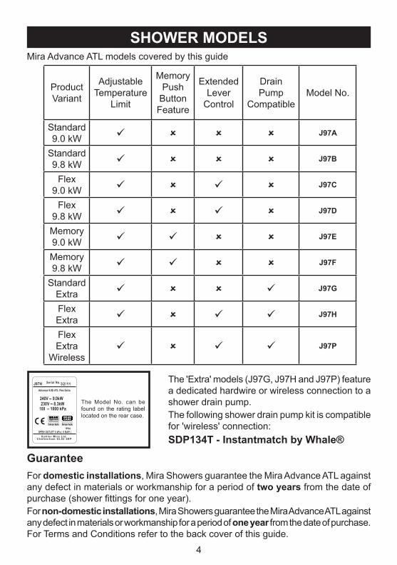
SHOWER MODELSMira Advance ATL models covered by this guide
Product Variant
Adjustable Temperature
Limit
Memory Push
Button Feature
Extended Lever
Control
Drain Pump
CompatibleModel No.
Standard 9.0 kW J97A
Standard 9.8 kW J97B
Flex 9.0 kW J97C
Flex 9.8 kW J97D
Memory 9.0 kW J97E
Memory 9.8 kW J97F
Standard Extra J97G
Flex Extra J97H
Flex Extra
Wireless J97P
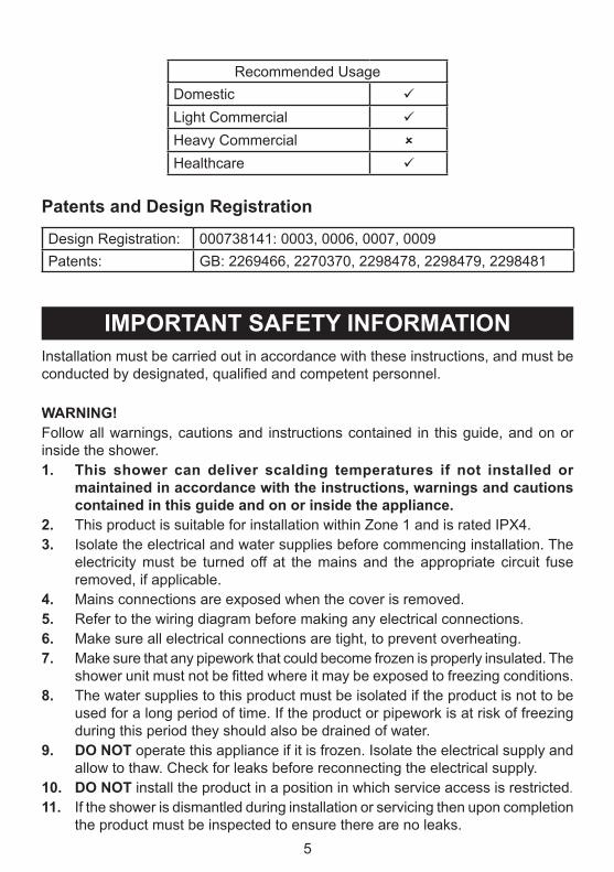
GuaranteeFor domestic installations, Mira Showers guarantee the Mira Advance ATL against any defect in materials or workmanship for a period of two years from the date of purchase (shower fittings for one year).For non-domestic installations, Mira Showers guarantee the Mira Advance ATL against any defect in materials or workmanship for a period of one year from the date of purchase. For Terms and Conditions refer to the back cover of this guide.
J97H 32/11Advance 9.0S ATL Flex Extra
Serial No.
OPEN OUTLET 0 kPa ( 0 BAR )IPX4
230V 8.3kW100 – 1000 kPa
Kohle r M i ra L td .Che l tenham GL52 5EP
The Model No. can be found on the rating label located on the rear case.
The 'Extra' models (J97G, J97H and J97P) feature a dedicated hardwire or wireless connection to a shower drain pump.The following shower drain pump kit is compatible for 'wireless' connection:SDP134T - Instantmatch by Whale®
IMPORTANT SAFETY INFORMATIONInstallation must be carried out in accordance with these instructions, and must be conducted by designated, qualified and competent personnel.
WARNING! Follow all warnings, cautions and instructions contained in this guide, and on or inside the shower.1. This shower can deliver scalding temperatures if not installed or
maintained in accordance with the instructions, warnings and cautions contained in this guide and on or inside the appliance.
2. This product is suitable for installation within Zone 1 and is rated IPX4. 3. Isolate the electrical and water supplies before commencing installation. The
electricity must be turned off at the mains and the appropriate circuit fuse removed, if applicable.
4. Mains connections are exposed when the cover is removed.5. Refer to the wiring diagram before making any electrical connections.6. Make sure all electrical connections are tight, to prevent overheating. 7. Make sure that any pipework that could become frozen is properly insulated. The
shower unit must not be fitted where it may be exposed to freezing conditions.8. The water supplies to this product must be isolated if the product is not to be
used for a long period of time. If the product or pipework is at risk of freezing during this period they should also be drained of water.
9. DO NOT operate this appliance if it is frozen. Isolate the electrical supply and allow to thaw. Check for leaks before reconnecting the electrical supply.
10. DO NOT install the product in a position in which service access is restricted.
11. If the shower is dismantled during installation or servicing then upon completion the product must be inspected to ensure there are no leaks.
6
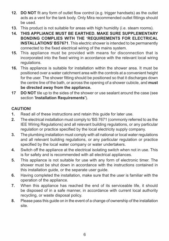
12. DO NOT fit any form of outlet flow control (e.g. trigger handsets) as the outlet acts as a vent for the tank body. Only Mira recommended outlet fittings should be used.
13. This product is not suitable for areas with high humidity (i.e. steam rooms).14. THIS APPLIANCE MUST BE EARTHED. MAKE SURE SUPPLEMENTARY
BONDING COMPLIES WITH THE ‘REQUIREMENTS FOR ELECTRICAL INSTALLATIONS’ BS7671. This electric shower is intended to be permanently connected to the fixed electrical wiring of the mains system.
15. This appliance must be provided with means for disconnection that is incorporated into the fixed wiring in accordance with the relevant local wiring regulations.
16. This appliance is suitable for installation within the shower area. It must be positioned over a water catchment area with the controls at a convenient height for the user. The shower fitting should be positioned so that it discharges down the centre line of the bath, or across the opening of a shower cubicle, and must be directed away from the appliance.
17 DO NOT tile up to the sides of the shower or use sealant around the case (see section 'Installation Requirements').
CAUTION!1. Read all of these instructions and retain this guide for later use.2. The electrical installation must comply to 'BS 7671 (commonly referred to as the
IEE Wiring Regulations) and all relevant building regulations, or any particular regulation or practice specified by the local electricity supply company.
3. The plumbing installation must comply with all national or local water regulations and all relevant building regulations, or any particular regulation or practice specified by the local water company or water undertakers.
4. Switch off the appliance at the electrical isolating switch when not in use. This is for safety and is recommended with all electrical appliances.
5. This appliance is not suitable for use with any form of electronic timer. The shower must be shut down in accordance with the instructions contained in this installation guide, or the separate user guide.
6. Having completed the installation, make sure that the user is familiar with the operation of the appliance.
7. When this appliance has reached the end of its serviceable life, it should be disposed of in a safe manner, in accordance with current local authority recycling, or waste disposal policy.
8. Please pass this guide on in the event of a change of ownership of the installation site.
7
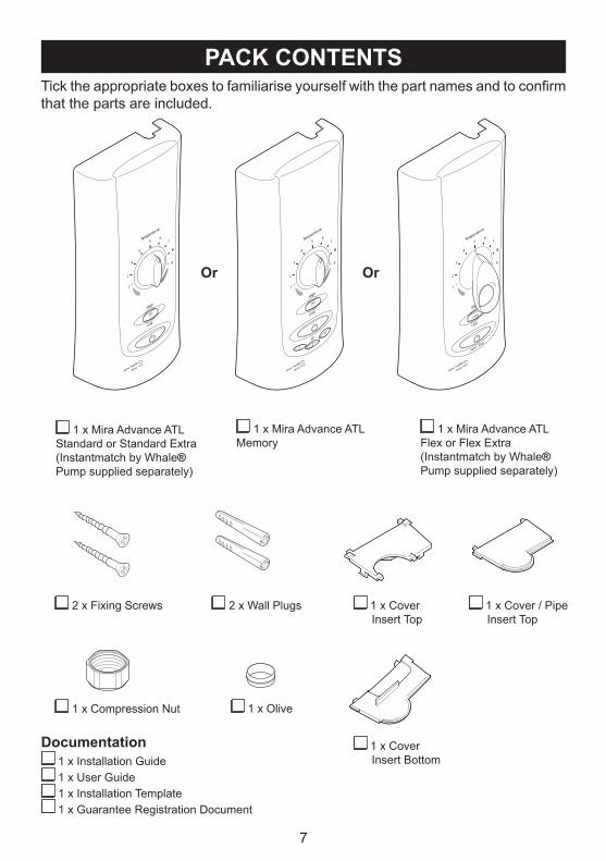
PACK CONTENTSTick the appropriate boxes to familiarise yourself with the part names and to confirm that the parts are included.
Documentation 1 x Installation Guide 1 x User Guide 1 x Installation Template 1 x Guarantee Registration Document
1 x Olive 1 x Compression Nut
1 x Mira Advance ATL Standard or Standard Extra (Instantmatch by Whale® Pump supplied separately)
Or Or
1 x Mira Advance ATL Memory
1 x Mira Advance ATL Flex or Flex Extra (Instantmatch by Whale® Pump supplied separately)
1 x Cover Insert Top
2 x Fixing Screws 2 x Wall Plugs 1 x Cover / Pipe Insert Top
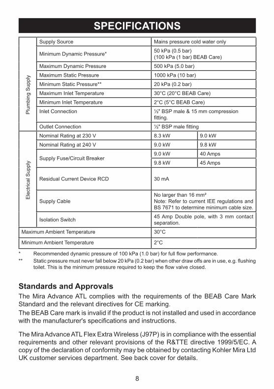
Inlet Connection ½" BSP male & 15 mm compression fitting.
Outlet Connection ½" BSP male fitting
Ele
ctric
al S
uppl
y
Nominal Rating at 230 V 8.3 kW 9.0 kW
Nominal Rating at 240 V 9.0 kW 9.8 kW
Supply Fuse/Circuit Breaker9.0 kW 40 Amps
9.8 kW 45 Amps
Residual Current Device RCD 30 mA
Supply CableNo larger than 16 mm²Note: Refer to current IEE regulations and BS 7671 to determine minimum cable size.
Isolation Switch 45 Amp Double pole, with 3 mm contact separation.
Maximum Ambient Temperature 30°C
Minimum Ambient Temperature 2°C
* Recommended dynamic pressure of 100 kPa (1.0 bar) for full flow performance.** Static pressure must never fall below 20 kPa (0.2 bar) when other draw offs are in use, e.g. flushing
toilet. This is the minimum pressure required to keep the flow valve closed.
Standards and ApprovalsThe Mira Advance ATL complies with the requirements of the BEAB Care Mark Standard and the relevant directives for CE marking.The BEAB Care mark is invalid if the product is not installed and used in accordance with the manufacturer's specifications and instructions.
The Mira Advance ATL Flex Extra Wireless (J97P) is in compliance with the essential requirements and other relevant provisions of the R&TTE directive 1999/5/EC. A copy of the declaration of conformity may be obtained by contacting Kohler Mira Ltd UK customer services department. See back cover for details.
9
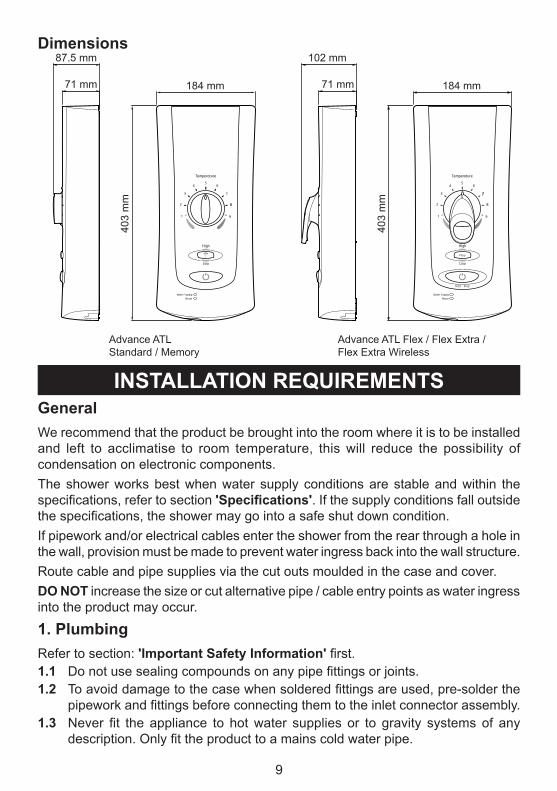
Dimensions
Advance ATL Standard / Memory
Advance ATL Flex / Flex Extra / Flex Extra Wireless
403
mm
184 mm
87.5 mm
71 mm
403
mm
184 mm
102 mm
71 mm
INSTALLATION REQUIREMENTSGeneralWe recommend that the product be brought into the room where it is to be installed and left to acclimatise to room temperature, this will reduce the possibility of condensation on electronic components.The shower works best when water supply conditions are stable and within the specifications, refer to section 'Specifications'. If the supply conditions fall outside the specifications, the shower may go into a safe shut down condition.If pipework and/or electrical cables enter the shower from the rear through a hole in the wall, provision must be made to prevent water ingress back into the wall structure.Route cable and pipe supplies via the cut outs moulded in the case and cover. DO NOT increase the size or cut alternative pipe / cable entry points as water ingress into the product may occur.
1. PlumbingRefer to section: 'Important Safety Information' first.1.1 Do not use sealing compounds on any pipe fittings or joints.1.2 To avoid damage to the case when soldered fittings are used, pre-solder the
pipework and fittings before connecting them to the inlet connector assembly.1.3 Never fit the appliance to hot water supplies or to gravity systems of any
description. Only fit the product to a mains cold water pipe.
10
1.4 Avoid layouts where the shower hose will be sharply kinked. This may reduce the life of the hose.
1.5 Supply pipework MUST be flushed to clear debris before connecting the appliance. Debris will reduce the performance of the shower and may damage the product.
Avoid running the pipework through excessively hot or cold areas such as hot loft spaces, airing cupboards, or in close proximity to hot water pipes. If this cannot be avoided, we would recommend insulating the pipes.
1.6 The shower must be fitted onto a tiled or sealed finished surface, i.e. on top of the tiles: [DO NOT tile up to the sides of the shower or use a sealant around the case.] Failure to do this may cause appliance failure. To ensure the case and other components are not put under strain during installation always provide mechanical support when making plumbing connections. Upon completion of the installation ensure connections and back case are not under any stress due to misaligned pipework or electrical cables.
1.7 We recommend that a non-restrictive (free flowing) isolating valve is fitted in the cold water supply pipe to allow maintenance of the appliance.
1.8 When installed in very hard water areas (above 200 ppm temporary hardness) your installer may advise the installation of a water treatment device, to reduce the effects of limescale formation. Any malfunction due to limescale is not covered by the manufacturer's guarantee. Your local water company will be able to advise the hardness of water in your area.
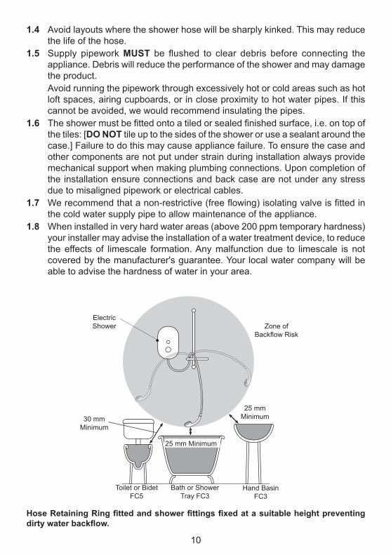
Hose Retaining Ring fitted and shower fittings fixed at a suitable height preventing dirty water backflow.
Zone of Backflow Risk
30 mm Minimum
Toilet or Bidet FC5
Hand Basin FC3
Bath or Shower Tray FC3
Electric Shower
25 mm Minimum
25 mm Minimum
11
2. ElectricalRefer to section: 'Important Safety Information' first.2.1 In a domestic installation, the rating of the electricity supplier’s fuse and the
consumer unit must be adequate for the additional demand. All Mira Advance ATL electric showers are high power appliances. Voltage drop due to local heavy demand will reduce the shower’s performance.
2.2 The appliance must be earthed by connecting the supply-cable earth conductor to the earth terminal.
Any supplementary bonding and supply cable size must conform to BS 7671.2.3 As a guide only, and in accordance with BS 7671 we recommend close circuit
protection:i.e. 9.0 kW = 40 Amp 9.8 kW = 45 Amp
In accordance with BS 7671, a 30 mA Residual Current Device (RCD) MUST be included in the electrical circuit. This may be part of the consumer unit or a separate unit.
A separate, permanently connected supply must taken from the consumer unit to the appliance through a double-pole switch, which has at least 3 mm contact separation. The switch can be a ceiling mounted pullcord type within the shower room or a wall mounted switch in the applicable zone area.
2.4 DO NOT exert strain on the terminal block. Make sure that the electrical connections are tightly screwed down.
2.5 DO NOT turn on the electrical supply until the plumbing has been completed.2.6 Unless otherwise stated, electrical equipment such as extractor fans, pumps
must not be connected via this product.
1.9 The position of the shower and shower fittings must provide a minimum gap of 25 mm between the showerhead and the spill over level of any bath, shower tray or basin and a minimum gap of 30 mm between the showerhead and the spill over level of any toilet, bidet or other appliance with a Fluid Category 5 backflow risk.
Note! There will be occasions when the hose retaining ring will not provide a suitable solution for Fluid Category 3 installations, in these instances an outlet double checkvalve must be fitted, this will increase the required supply pressure typically by 10kPa (0.1 bar). Double checkvalves fitted in the inlet supply to the appliance cause a pressure build up, which affect the maximum static inlet pressure for the appliance and must not be fitted. For Fluid category 5 double checkvalves are not suitable.
1.10 Wall fixings are supplied for solid wall structures. For other wall structures such as panels alternative fixings may be required. A minimum of 2 fixing screws must be used.
12
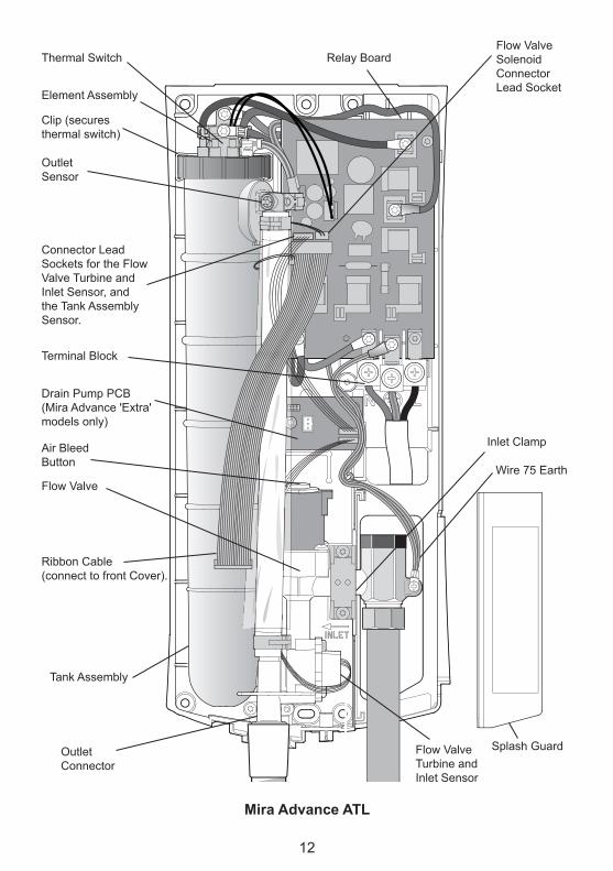
Terminal Block
Tank Assembly
Outlet Connector
Flow Valve Turbine and Inlet Sensor
Wire 75 Earth
Inlet Clamp
Splash Guard
Relay BoardFlow Valve Solenoid Connector Lead Socket
Thermal Switch
Element Assembly
Clip (secures thermal switch)
Outlet Sensor
Connector Lead Sockets for the Flow Valve Turbine and Inlet Sensor, and the Tank Assembly Sensor.
Ribbon Cable(connect to front Cover).
Flow Valve
Air Bleed Button
Drain Pump PCB(Mira Advance 'Extra' models only)
Mira Advance ATL
13
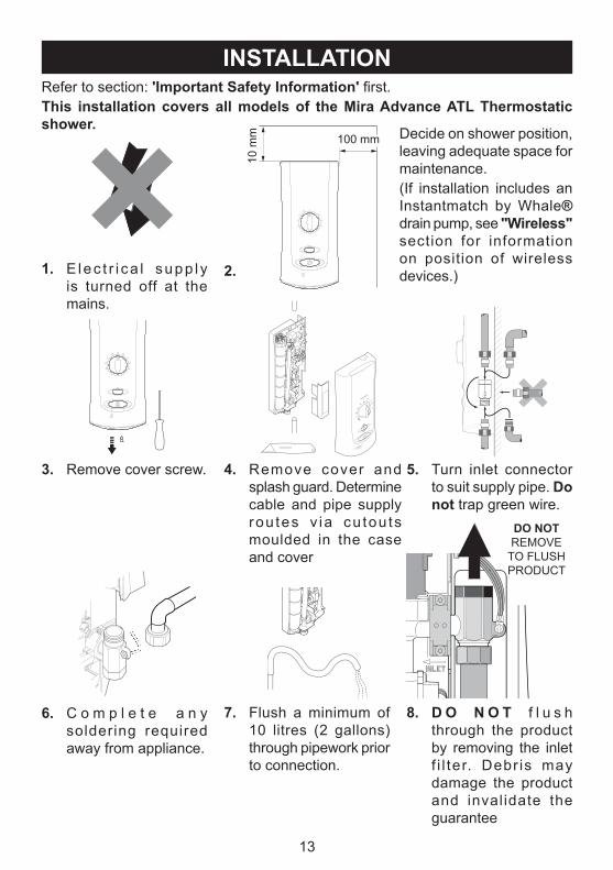
INSTALLATIONRefer to section: 'Important Safety Information' first.This installation covers all models of the Mira Advance ATL Thermostatic shower.
1. E lec t r i ca l supp l y is turned off at the mains.
2.
Decide on shower position, leaving adequate space for maintenance.(If installation includes an Instantmatch by Whale® drain pump, see "Wireless" section for information on position of wireless devices.)
3. Remove cover screw. 5. Turn inlet connector to suit supply pipe. Do not trap green wire.
6. C o m p l e t e a n y soldering required away from appliance.
8. D O N O T f l u s h through the product by removing the inlet f i l ter. Debr is may damage the product and invalidate the guarantee
7. Flush a minimum of 10 litres (2 gallons) through pipework prior to connection.
10 m
m 100 mm
4. Remove cover and splash guard. Determine cable and pipe supply rou tes v ia cu tou ts moulded in the case and cover
DO NOT REMOVE
TO FLUSH PRODUCT
14
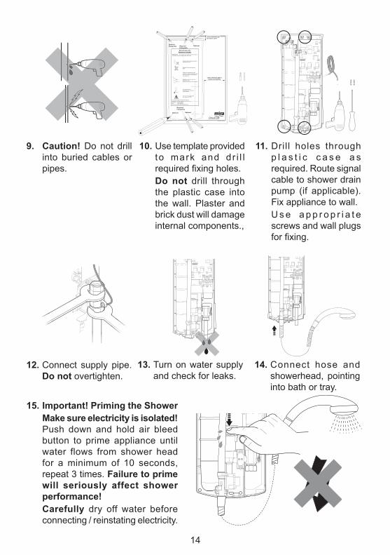
9. Caution! Do not drill into buried cables or pipes.
10. Use template provided to mark and dr i l l required fixing holes.
Do not drill through the plastic case into the wall. Plaster and brick dust will damage internal components.,
Mira Advance ATLAttention Installer
IMPORTANT! The following key details should be read in conjunction with the Installation and User Guide.
For technical support and general enquires, spare parts and after sales service contact us on:Telephone : 0870 241 0888Fax : 01242 282 595email : [email protected]
Optional Optional
Leave minimum gap to install and maintain
Do not install the appliance where it may become frozen.
Do not drill into buried cables or pipes.
Avoid dust contamination of the product by using this template to mark and drill into the wall. Drill appliance case separately.
Do not use alternative screws to secure the cover.Do not seal any part of the appliance.
Use the correct supply cable size. Refer to BS 7671.
Leave minimum gap to remove cover
Required Fixing Hole
Thoroughly fl ush the pipework before connecting to the appliance.
11. Drill holes through p l a s t i c c a s e a s required. Route signal cable to shower drain pump (if applicable). Fix appliance to wall.
U s e a p p r o p r i a t e screws and wall plugs for fixing.
14. Connect hose and showerhead, pointing into bath or tray.
13. Turn on water supply and check for leaks.
12. Connect supply pipe. Do not overtighten.
15. Important! Priming the Shower Make sure electricity is isolated!
Push down and hold air bleed button to prime appliance until water flows from shower head for a minimum of 10 seconds, repeat 3 times. Failure to prime will seriously affect shower performance!
Carefully dry off water before connecting / reinstating electricity.
15
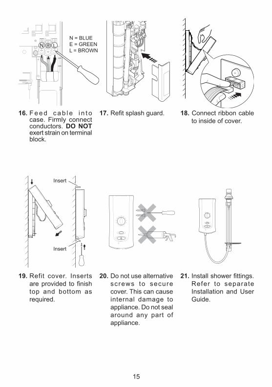
17. Refit splash guard.
N = BLUEE = GREENL = BROWN
N L
16. F e e d c a b l e i n t o case. Firmly connect conductors. DO NOT exert strain on terminal block.
20. Do not use alternative screws to secure cover. This can cause internal damage to appliance. Do not seal around any part of appliance.
21. Install shower fittings. Refer to separate Installation and User Guide.
19. Refit cover. Inserts are provided to finish top and bottom as required.
18. Connect ribbon cable to inside of cover.
Insert
Insert
16
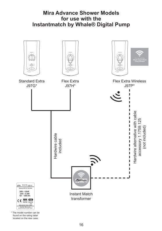
Mira Advance Shower Modelsfor use with the
Instantmatch by Whale® Digital Pump
Standard Extra J97G*
Instant Match transformer
Flex Extra J97H*
Flex Extra Wireless J97P*
Har
dwire
alte
rnat
ive
with
cab
le
acce
ssor
y 1.
1759
.125
(n
ot in
clud
ed)
Har
dwire
cab
le
incl
uded
For use with theWhale Instant Match
Pump Wireless
Instant Match
For use with theWhale Instant Match
Pump Wireless
Instant Match
J97H 32/11Advance 9.0S ATL Flex Extra
Serial No.
OPEN OUTLET 0 kPa ( 0 BAR )IPX4
230V 8.3kW100 – 1000 kPa
Kohle r M i ra L td .Che l tenham GL52 5EP
* The model number can be found on the rating label located on the rear case.
17
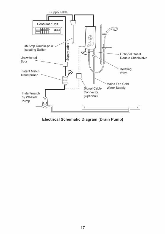
Electrical Schematic Diagram (Drain Pump)
Optional Outlet Double Checkvalve
45 Amp Double-pole Isolating Switch
Mains Fed Cold Water SupplySignal Cable
Connector (Optional)
Consumer Unit
Isolating Valve
Unswitched Spur
Instant Match Transformer
Instantmatch by Whale® Pump
Supply cable
Sup
ply
cabl
e
18
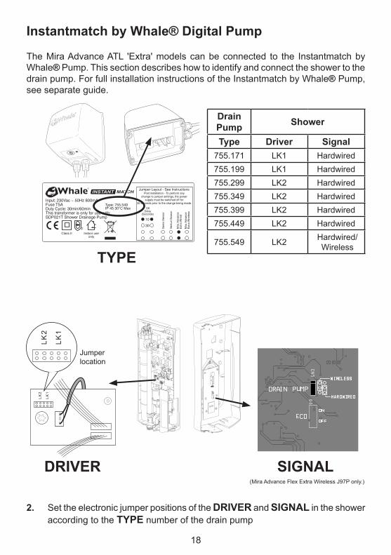
Instantmatch by Whale® Digital Pump
The Mira Advance ATL 'Extra' models can be connected to the Instantmatch by Whale® Pump. This section describes how to identify and connect the shower to the drain pump. For full installation instructions of the Instantmatch by Whale® Pump, see separate guide.
1. Identify the drain pump model using the TYPE number in the table. The corresponding number is shown on the drain pump transformer.
2. Set the electronic jumper positions of the DRIVER and SIGNAL in the shower according to the TYPE number of the drain pump
Input: 230Vac ~ 50Hz 800mAFuse T5ADuty Cycle: 30min/60minThis transformer is only for use with:SDP021T Shower Drainage Pump
Type: 755.549IP 45 30°C Max
Class II Indoor use only
F
Jumper Layout - See InstructionsPost installation - To perform any
change to jumper settings, the powersupply must be switched off for
30 seconds prior to the change being made.
OffDelay
(Seconds)
10
30
Gem
s S
enso
r
Ven
turi
Sen
sor
Mira
Adv
ance
E
xtra
Wire
d
Mira
Adv
ance
E
xtra
Wire
less
19
Maximum for
Wireless Signal
Range = 5 metresShower
Bathroom
Drain Pump
to waste
ConsumerUnitDrain Pump
Transformer
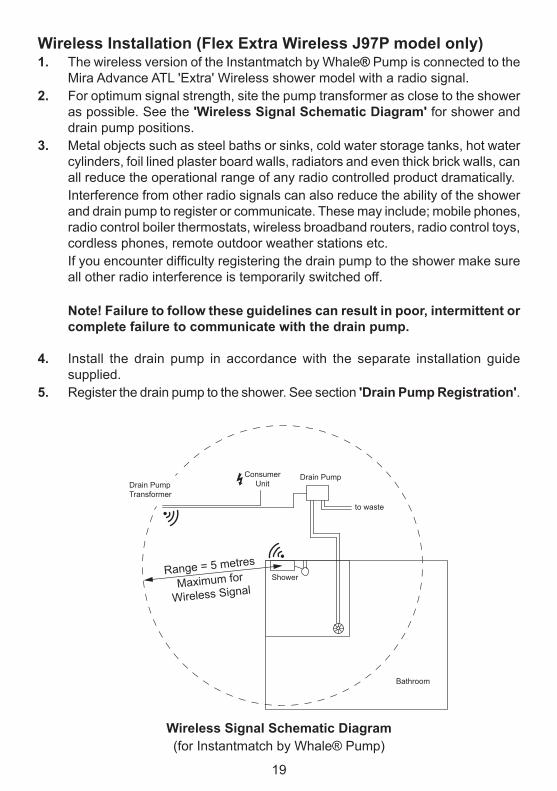
Wireless Installation (Flex Extra Wireless J97P model only)1. The wireless version of the Instantmatch by Whale® Pump is connected to the
Mira Advance ATL 'Extra' Wireless shower model with a radio signal.2. For optimum signal strength, site the pump transformer as close to the shower
as possible. See the 'Wireless Signal Schematic Diagram' for shower and drain pump positions.
3. Metal objects such as steel baths or sinks, cold water storage tanks, hot water cylinders, foil lined plaster board walls, radiators and even thick brick walls, can all reduce the operational range of any radio controlled product dramatically.Interference from other radio signals can also reduce the ability of the shower and drain pump to register or communicate. These may include; mobile phones, radio control boiler thermostats, wireless broadband routers, radio control toys, cordless phones, remote outdoor weather stations etc.If you encounter difficulty registering the drain pump to the shower make sure all other radio interference is temporarily switched off.
Note! Failure to follow these guidelines can result in poor, intermittent or complete failure to communicate with the drain pump.
4. Install the drain pump in accordance with the separate installation guide supplied.
5. Register the drain pump to the shower. See section 'Drain Pump Registration'.
Wireless Signal Schematic Diagram(for Instantmatch by Whale® Pump)
20
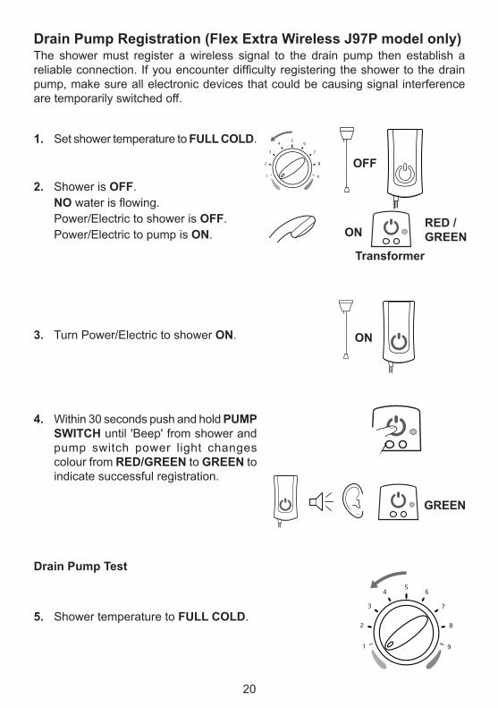
Drain Pump Registration (Flex Extra Wireless J97P model only)The shower must register a wireless signal to the drain pump then establish a reliable connection. If you encounter difficulty registering the shower to the drain pump, make sure all electronic devices that could be causing signal interference are temporarily switched off.
Drain Pump Test
1. Set shower temperature to FULL COLD.
2. Shower is OFF. NO water is flowing. Power/Electric to shower is OFF. Power/Electric to pump is ON. ON
RED / GREEN
OFF
3. Turn Power/Electric to shower ON.
5. Shower temperature to FULL COLD.
ON
Transformer
4. Within 30 seconds push and hold PUMP SWITCH until 'Beep' from shower and pump switch power light changes colour from RED/GREEN to GREEN to indicate successful registration.
GREEN
21
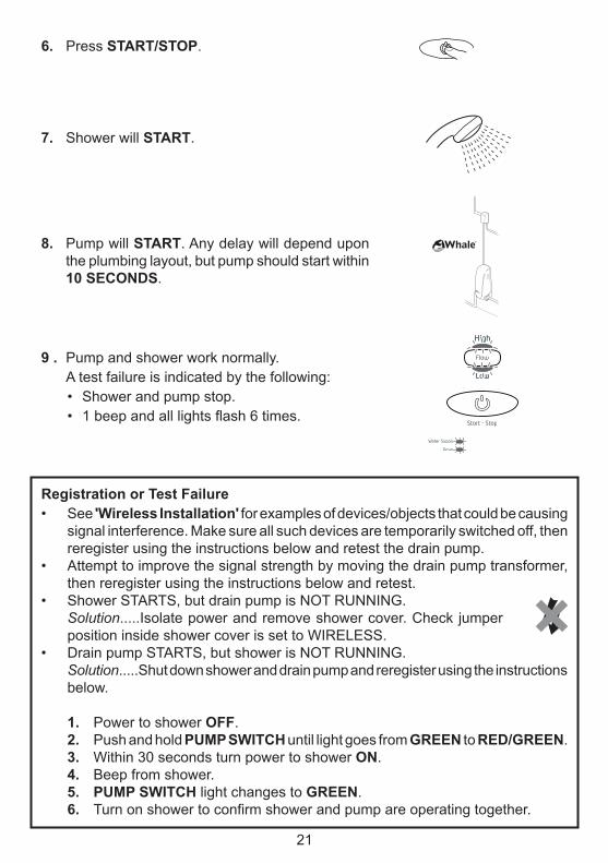
6. Press START/STOP.
Registration or Test Failure• See 'Wireless Installation' for examples of devices/objects that could be causing
signal interference. Make sure all such devices are temporarily switched off, then reregister using the instructions below and retest the drain pump.
• Attempt to improve the signal strength by moving the drain pump transformer, then reregister using the instructions below and retest.
• Shower STARTS, but drain pump is NOT RUNNING.Solution.....Isolate power and remove shower cover. Check jumper position inside shower cover is set to WIRELESS.
• Drain pump STARTS, but shower is NOT RUNNING.Solution.....Shut down shower and drain pump and reregister using the instructions below.
1. Power to shower OFF.2. Push and hold PUMP SWITCH until light goes from GREEN to RED/GREEN.3. Within 30 seconds turn power to shower ON.4. Beep from shower.5. PUMP SWITCH light changes to GREEN.6. Turn on shower to confirm shower and pump are operating together.
8. Pump will START. Any delay will depend upon the plumbing layout, but pump should start within 10 SECONDS.
9 . Pump and shower work normally. A test failure is indicated by the following:
• Shower and pump stop.• 1 beep and all lights flash 6 times.
R
7. Shower will START.
22
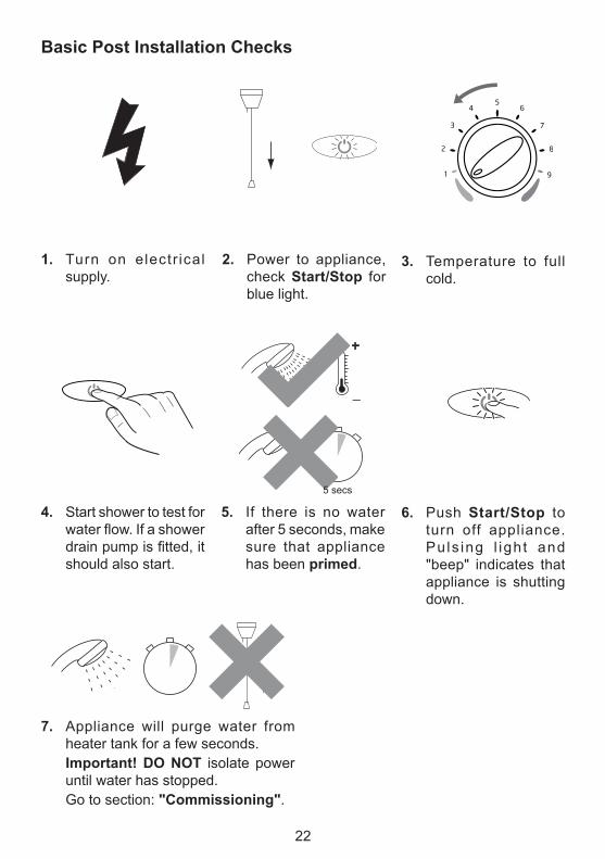
Basic Post Installation Checks
1. Turn on electr ical supply.
3. Temperature to full cold.
4. Start shower to test for water flow. If a shower drain pump is fitted, it should also start.
5. If there is no water after 5 seconds, make sure that appliance has been primed.
5 secs
2. Power to appliance, check Start/Stop for blue light.
6. Push Start/Stop to turn off appliance. Pu ls ing l igh t and "beep" indicates that appliance is shutting down.
7. Appliance will purge water from heater tank for a few seconds.
Important! DO NOT isolate power until water has stopped.
Go to section: "Commissioning".
23
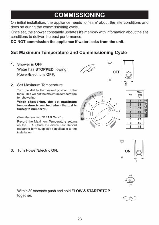
COMMISSIONINGOn initial installation, the appliance needs to 'learn' about the site conditions and does so during the commissioning cycle.Once set, the shower constantly updates it's memory with information about the site conditions to deliver the best performance.DO NOT commission the appliance if water leaks from the unit.
Set Maximum Temperature and Commissioning Cycle
1. Shower is OFF. Water has STOPPED flowing. Power/Electric is OFF.
3. Turn Power/Electric ON.
Within 30 seconds push and hold FLOW & START/STOP together.
OFF
ON
2. Set Maximum Temperature Turn the dial to the desired position in the
table. This will set the maximum temperature for showering.
When showering, the set maximum temperature is reached when the dial is turned to number '9'.
(See also section: "BEAB Care".) Record the Maximum Temperature setting
on the BEAB Care In-Service Test Record (separate form supplied) if applicable to the installation.
BE
AB
Car
e Range 1-5 No.
Max. Temp
°C1 372 383 394 405 416 427 458 48
BE
AB
CA
RE
24
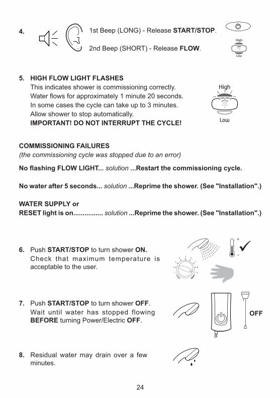
1st Beep (LONG) - Release START/STOP.
2nd Beep (SHORT) - Release FLOW.
4.
5. HIGH FLOW LIGHT FLASHES This indicates shower is commissioning correctly. Water flows for approximately 1 minute 20 seconds. In some cases the cycle can take up to 3 minutes. Allow shower to stop automatically. IMPORTANT! DO NOT INTERRUPT THE CYCLE!
6. Push START/STOP to turn shower ON. Check that maximum temperature is
acceptable to the user.
COMMISSIONING FAILURES(the commissioning cycle was stopped due to an error)
No flashing FLOW LIGHT... solution ...Restart the commissioning cycle.
No water after 5 seconds... solution ...Reprime the shower. (See "Installation".)
WATER SUPPLY or RESET light is on................ solution ...Reprime the shower. (See "Installation".)
_
+
7. Push START/STOP to turn shower OFF. Wait until water has stopped flowing
BEFORE turning Power/Electric OFF.
8. Residual water may drain over a few minutes.
OFF
25
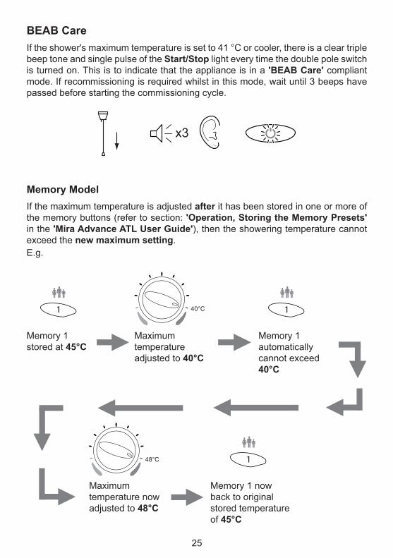
BEAB CareIf the shower's maximum temperature is set to 41 °C or cooler, there is a clear triple beep tone and single pulse of the Start/Stop light every time the double pole switch is turned on. This is to indicate that the appliance is in a 'BEAB Care' compliant mode. If recommissioning is required whilst in this mode, wait until 3 beeps have passed before starting the commissioning cycle.
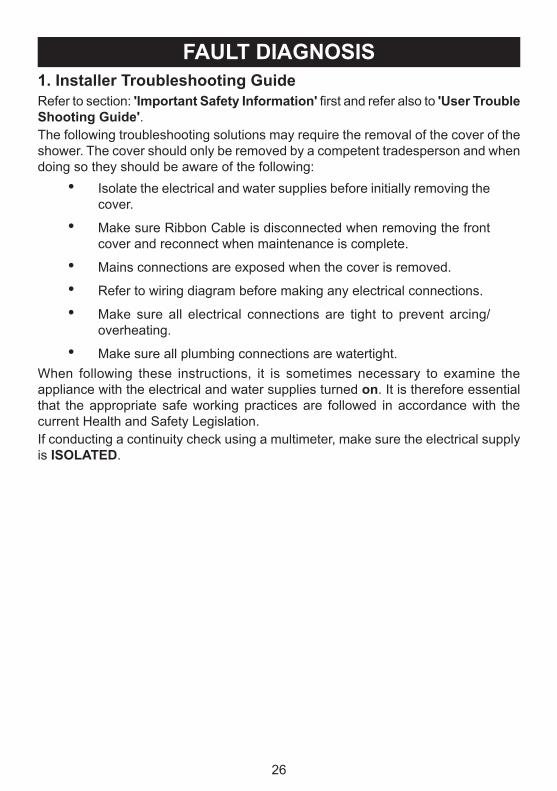
Memory ModelIf the maximum temperature is adjusted after it has been stored in one or more of the memory buttons (refer to section: 'Operation, Storing the Memory Presets' in the 'Mira Advance ATL User Guide'), then the showering temperature cannot exceed the new maximum setting.E.g.
Memory 1 stored at 45°C
Maximum temperature adjusted to 40°C
Memory 1 automatically cannot exceed 40°C
Maximum temperature now adjusted to 48°C
Memory 1 now back to original stored temperature of 45°C
40°C
48°C
x3
26
FAULT DIAGNOSIS1. Installer Troubleshooting GuideRefer to section: 'Important Safety Information' first and refer also to 'User Trouble Shooting Guide'.The following troubleshooting solutions may require the removal of the cover of the shower. The cover should only be removed by a competent tradesperson and when doing so they should be aware of the following:
• Isolate the electrical and water supplies before initially removing the cover.
• Make sure Ribbon Cable is disconnected when removing the front cover and reconnect when maintenance is complete.
• Mains connections are exposed when the cover is removed.
• Refer to wiring diagram before making any electrical connections.
• Make sure all electrical connections are tight to prevent arcing/overheating.
• Make sure all plumbing connections are watertight.When following these instructions, it is sometimes necessary to examine the appliance with the electrical and water supplies turned on. It is therefore essential that the appropriate safe working practices are followed in accordance with the current Health and Safety Legislation.If conducting a continuity check using a multimeter, make sure the electrical supply is ISOLATED.
27
2. DIAGNOSTIC PROCEDURE1. Ensure the shower pullcord / isolator switch is in the OFF position, then turn
ON the pullcord / isolator switch.2. If the unit ‘Beeps’ & the Start / Stop button is flashing WAIT for 20 SECONDS
until the button stops flashing.NOTE! If the Start / Stop button continues to flash & no beep was heard upon start up, refer to ERROR CODE 16 on the fault code sheet.
3. Start the shower & observe light fault indication (if any) & refer to Error Code Sheet to determine failure and rectify.NOTE! If the shower operates normally run the unit for at least 5 minutes at showering temperature & ensure the temperature remains stable.
4. Turn the shower off at the Start / Stop Button & observe ‘phased shutdown’. DO NOT isolate the power at the pullcord / isolator switch until the water flow stops.
5. Turn off the power at the pullcord / isolator switch, then turn the power back on and commission the shower.
6. Run the shower for at least 5 minutes.7. Show the user the correct start / stop procedure and general operation of the
shower. Advise user that isolating the shower before the flow has stopped may damage the shower.For the fault codes 0 to 14 and 18, the reset light will be on or flashing. This will require the shower to be turned off at the pullcord / isolator switch to reset the unit. When the pullcord / isolation switch is turned back on the shower may beep and the Start / Stop button may flash. If this occurs go back to action number 2 and re-follow the Diagnostic Procedure.
28
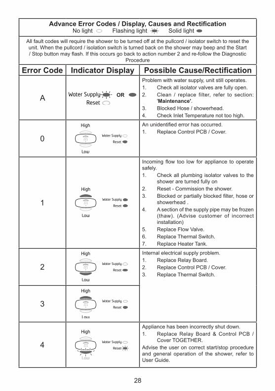
Advance Error Codes / Display, Causes and Rectification
All fault codes will require the shower to be turned off at the pullcord / isolator switch to reset the unit. When the pullcord / isolation switch is turned back on the shower may beep and the Start / Stop button may flash. If this occurs go back to action number 2 and re-follow the Diagnostic
Procedure
Error Code Indicator Display Possible Cause/Rectification
A OR
Problem with water supply, unit still operates.1. Check all isolator valves are fully open.2. Clean / replace filter, refer to section:
'Maintenance'.3. Blocked Hose / showerhead.4. Check Inlet Temperature not too high.
0
An unidentified error has occurred.1. Replace Control PCB / Cover.
1
Incoming flow too low for appliance to operate safely. 1. Check all plumbing isolator valves to the
shower are turned fully on2. Reset - Commission the shower.3. Blocked or partially blocked filter, hose or
showerhead .4. A section of the supply pipe may be frozen
(thaw). (Advise customer of incorrect installation)
Appliance has been incorrectly shut down.1. Replace Relay Board & Control PCB /
Cover TOGETHER.Advise the user on correct start/stop procedure and general operation of the shower, refer to User Guide.
29
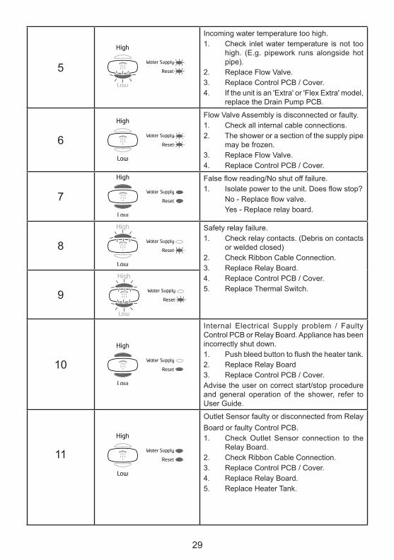
5
Incoming water temperature too high.1. Check inlet water temperature is not too
high. (E.g. pipework runs alongside hot pipe).
2. Replace Flow Valve.3. Replace Control PCB / Cover.4. If the unit is an 'Extra' or 'Flex Extra' model,
replace the Drain Pump PCB.
6
Flow Valve Assembly is disconnected or faulty.1. Check all internal cable connections.2. The shower or a section of the supply pipe
may be frozen.3. Replace Flow Valve.4. Replace Control PCB / Cover.
7
False flow reading/No shut off failure.1. Isolate power to the unit. Does flow stop? No - Replace flow valve. Yes - Replace relay board.
8
Safety relay failure.1. Check relay contacts. (Debris on contacts
or welded closed)2. Check Ribbon Cable Connection.3. Replace Relay Board. 4. Replace Control PCB / Cover.5. Replace Thermal Switch.9
10
Internal Electrical Supply problem / Faulty Control PCB or Relay Board. Appliance has been incorrectly shut down.1. Push bleed button to flush the heater tank.2. Replace Relay Board3. Replace Control PCB / Cover.Advise the user on correct start/stop procedure and general operation of the shower, refer to User Guide.
11
Outlet Sensor faulty or disconnected from Relay Board or faulty Control PCB.1. Check Outlet Sensor connection to the
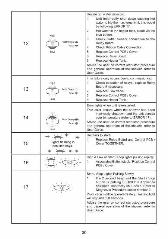
Unsafe hot water detected.1. Unit incorrectly shut down causing hot
water to trip the max temp limit, this would be following ERROR 17.
2. Hot water in the heater tank, bleed via the blue button.
3. Check Outlet Sensor connection to the Relay Board.
4. Check Ribbon Cable Connection.5. Replace Control PCB / Cover.6. Replace Relay Board.7. Replace Heater Tank.Advise the user on correct start/stop procedure and general operation of the shower, refer to User Guide.
13
This failure only occurs during commissioning.1. Check operation of relays / replace Relay
Board if necessary.2. Replace Flow valve. 3. Replace Control PCB / Cover.4. Replace Heater Tank.
14
Error lights when unit is re-started.This error occurs when the shower has been
incorrectly shutdown and the unit senses over temperature (refer to ERROR 17).
Advise the user on correct start/stop procedure and general operation of the shower, refer to User Guide.
15
Unit fails to start.1. Replace Relay Board and Control PCB /
Cover TOGETHER.
16High & Low or Start / Stop lights pulsing rapidly.1. Associated Button stuck / Replace Control
PCB / Cover.
17
Start / Stop Lights Pulsing Slowly 1. If a 2 second beep and the Start / Stop
button is pulsing SLOWLY = Appliance has been incorrectly shut down. Refer to Diagnostic Procedure action number 2.
Product can still be operated safely. Flashing light will stop after 20 seconds.Advise the user on correct start/stop procedure and general operation of the shower, refer to User Guide.
Lights flashing in peculiar ways.
31
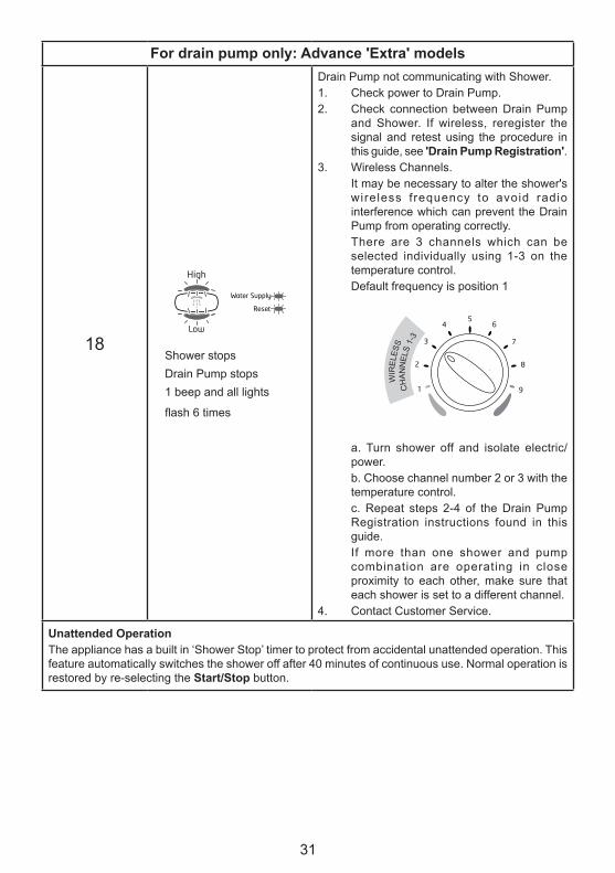
For drain pump only: Advance 'Extra' models
18
Drain Pump not communicating with Shower.1. Check power to Drain Pump.2. Check connection between Drain Pump
and Shower. If wireless, reregister the signal and retest using the procedure in this guide, see 'Drain Pump Registration'.
3. Wireless Channels.It may be necessary to alter the shower's wireless frequency to avoid radio interference which can prevent the Drain Pump from operating correctly.There are 3 channels which can be selected individually using 1-3 on the temperature control.Default frequency is position 1
a. Turn shower off and isolate electric/power.b. Choose channel number 2 or 3 with the temperature control.c. Repeat steps 2-4 of the Drain Pump Registration instructions found in this guide.If more than one shower and pump combination are operating in close proximity to each other, make sure that each shower is set to a different channel.
4. Contact Customer Service.
Unattended OperationThe appliance has a built in ‘Shower Stop’ timer to protect from accidental unattended operation. This feature automatically switches the shower off after 40 minutes of continuous use. Normal operation is restored by re-selecting the Start/Stop button.
CH
ANN
ELS
1-3
WIR
ELES
S
Shower stopsDrain Pump stops1 beep and all lights
flash 6 times
32
BEAB CARE IN-SERVICE TESTSThe following procedure applies to products operated and maintained within the BEAB Care requirements. This procedure should be conducted by designated, qualified and competent personnel only.
To maintain the validity of the BEAB Care mark, regular inspections of the installation and appliance should be carried out. The purpose of the in-service tests is to monitor and record the performance of the shower. Any deterioration in performance can indicate the need for maintenance work on the appliance and/or the water supplies.
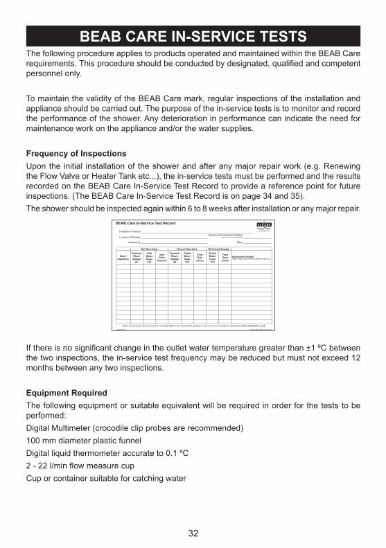
Frequency of InspectionsUpon the initial installation of the shower and after any major repair work (e.g. Renewing the Flow Valve or Heater Tank etc...), the in-service tests must be performed and the results recorded on the BEAB Care In-Service Test Record to provide a reference point for future inspections. (The BEAB Care In-Service Test Record is on page 34 and 35).The shower should be inspected again within 6 to 8 weeks after installation or any major repair.
If there is no significant change in the outlet water temperature greater than ±1 ºC between the two inspections, the in-service test frequency may be reduced but must not exceed 12 months between any two inspections.
Equipment RequiredThe following equipment or suitable equivalent will be required in order for the tests to be performed:Digital Multimeter (crocodile clip probes are recommended)100 mm diameter plastic funnelDigital liquid thermometer accurate to 0.1 ºC2 - 22 l/min flow measure cupCup or container suitable for catching water
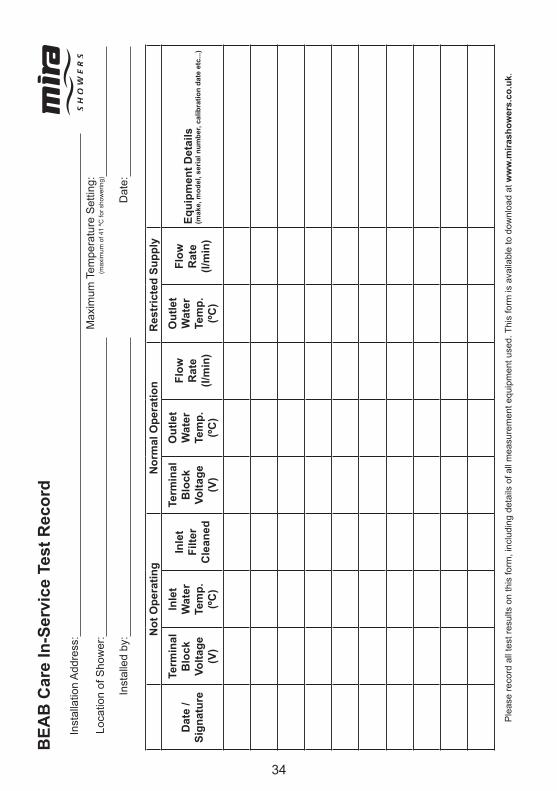
BEAB Care In-Service Test Record
Installation Address:
Location of Shower:Maximum Temperature Setting:
(maximum of 41 ºC for showering)
Installed by:
Please record all test results on this form, including details of all measurement equipment used. This form is available to download at www.mirashowers.co.uk.
(l/min)Equipment Details(make, model, serial number, calibration date etc...)
33
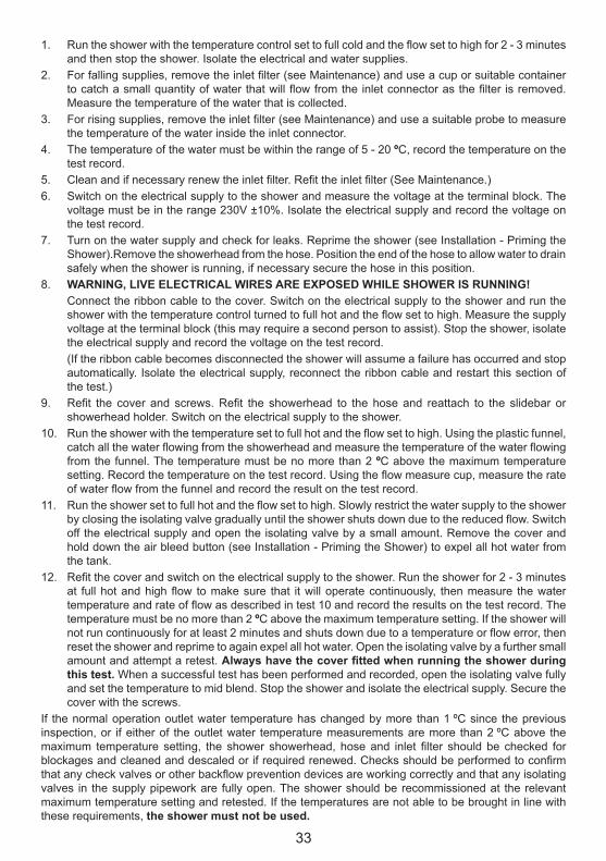
1. Run the shower with the temperature control set to full cold and the flow set to high for 2 - 3 minutes and then stop the shower. Isolate the electrical and water supplies.
2. For falling supplies, remove the inlet filter (see Maintenance) and use a cup or suitable container to catch a small quantity of water that will flow from the inlet connector as the filter is removed. Measure the temperature of the water that is collected.
3. For rising supplies, remove the inlet filter (see Maintenance) and use a suitable probe to measure the temperature of the water inside the inlet connector.
4. The temperature of the water must be within the range of 5 - 20 ºC, record the temperature on the test record.
5. Clean and if necessary renew the inlet filter. Refit the inlet filter (See Maintenance.)6. Switch on the electrical supply to the shower and measure the voltage at the terminal block. The
voltage must be in the range 230V ±10%. Isolate the electrical supply and record the voltage on the test record.
7. Turn on the water supply and check for leaks. Reprime the shower (see Installation - Priming the Shower).Remove the showerhead from the hose. Position the end of the hose to allow water to drain safely when the shower is running, if necessary secure the hose in this position.
8. WARNING, LIVE ELECTRICAL WIRES ARE EXPOSED WHILE SHOWER IS RUNNING!Connect the ribbon cable to the cover. Switch on the electrical supply to the shower and run the shower with the temperature control turned to full hot and the flow set to high. Measure the supply voltage at the terminal block (this may require a second person to assist). Stop the shower, isolate the electrical supply and record the voltage on the test record.(If the ribbon cable becomes disconnected the shower will assume a failure has occurred and stop automatically. Isolate the electrical supply, reconnect the ribbon cable and restart this section of the test.)
9. Refit the cover and screws. Refit the showerhead to the hose and reattach to the slidebar or showerhead holder. Switch on the electrical supply to the shower.
10. Run the shower with the temperature set to full hot and the flow set to high. Using the plastic funnel, catch all the water flowing from the showerhead and measure the temperature of the water flowing from the funnel. The temperature must be no more than 2 ºC above the maximum temperature setting. Record the temperature on the test record. Using the flow measure cup, measure the rate of water flow from the funnel and record the result on the test record.
11. Run the shower set to full hot and the flow set to high. Slowly restrict the water supply to the shower by closing the isolating valve gradually until the shower shuts down due to the reduced flow. Switch off the electrical supply and open the isolating valve by a small amount. Remove the cover and hold down the air bleed button (see Installation - Priming the Shower) to expel all hot water from the tank.
12. Refit the cover and switch on the electrical supply to the shower. Run the shower for 2 - 3 minutes at full hot and high flow to make sure that it will operate continuously, then measure the water temperature and rate of flow as described in test 10 and record the results on the test record. The temperature must be no more than 2 ºC above the maximum temperature setting. If the shower will not run continuously for at least 2 minutes and shuts down due to a temperature or flow error, then reset the shower and reprime to again expel all hot water. Open the isolating valve by a further small amount and attempt a retest. Always have the cover fitted when running the shower during this test. When a successful test has been performed and recorded, open the isolating valve fully and set the temperature to mid blend. Stop the shower and isolate the electrical supply. Secure the cover with the screws.
If the normal operation outlet water temperature has changed by more than 1 ºC since the previous inspection, or if either of the outlet water temperature measurements are more than 2 ºC above the maximum temperature setting, the shower showerhead, hose and inlet filter should be checked for blockages and cleaned and descaled or if required renewed. Checks should be performed to confirm that any check valves or other backflow prevention devices are working correctly and that any isolating valves in the supply pipework are fully open. The shower should be recommissioned at the relevant maximum temperature setting and retested. If the temperatures are not able to be brought in line with these requirements, the shower must not be used.
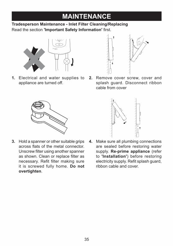
1. Electrical and water supplies to appliance are turned off.
2. Remove cover screw, cover and splash guard. Disconnect ribbon cable from cover
3. Hold a spanner or other suitable grips across flats of the metal connector. Unscrew filter using another spanner as shown. Clean or replace filter as necessary. Refit filter making sure it is screwed fully home. Do not overtighten.
4. Make sure all plumbing connections are sealed before restoring water supply. Re-prime appliance (refer to 'Installation') before restoring electricity supply. Refit splash guard, ribbon cable and cover.
36
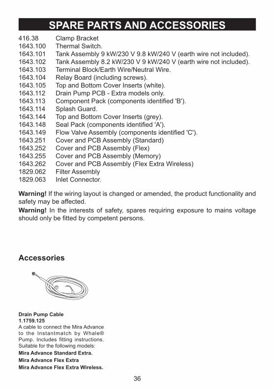
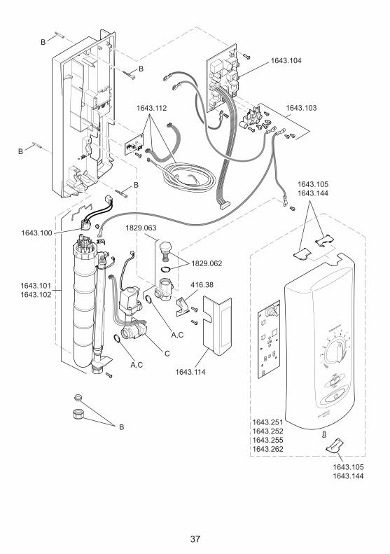
SPARE PARTS AND ACCESSORIES416.38 Clamp Bracket1643.100 Thermal Switch.1643.101 Tank Assembly 9 kW/230 V 9.8 kW/240 V (earth wire not included).1643.102 Tank Assembly 8.2 kW/230 V 9 kW/240 V (earth wire not included).1643.103 Terminal Block/Earth Wire/Neutral Wire.1643.104 Relay Board (including screws).1643.105 Top and Bottom Cover Inserts (white).1643.112 Drain Pump PCB - Extra models only.1643.113 Component Pack (components identified 'B').1643.114 Splash Guard.1643.144 Top and Bottom Cover Inserts (grey).1643.148 Seal Pack (components identified 'A').1643.149 Flow Valve Assembly (components identified 'C').1643.251 Cover and PCB Assembly (Standard)1643.252 Cover and PCB Assembly (Flex)1643.255 Cover and PCB Assembly (Memory)1643.262 Cover and PCB Assembly (Flex Extra Wireless)1829.062 Filter Assembly1829.063 Inlet Connector.
Warning! If the wiring layout is changed or amended, the product functionality and safety may be affected.Warning! In the interests of safety, spares requiring exposure to mains voltage should only be fitted by competent persons.
Drain Pump Cable1.1759.125A cable to connect the Mira Advance to the Instantmatch by Whale® Pump. Includes fitting instructions. Suitable for the following models:Mira Advance Standard Extra.Mira Advance Flex ExtraMira Advance Flex Extra Wireless.
Accessories
37
B
1829.062
1643.100
1643.1011643.102
1643.103
1643.104
1643.105 1643.144
1643.105 1643.144
1643.2511643.2521643.2551643.262
1643.112
B
B
B
B
1643.114
C
A,C
416.38
A,C
1829.063
38
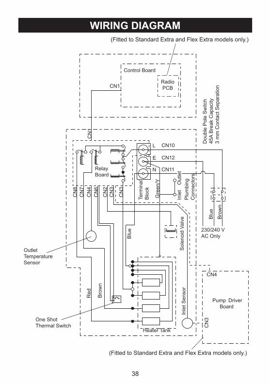
WIRING DIAGRAM
RelayBoard
N
Inle
t Sen
sor
Red
Bro
wn
Sol
enoi
d Va
lve
230/240 VAC Only
Bro
wn
Dou
ble
Pol
e S
witc
h45
A B
reak
Cap
acity
3 m
m C
onta
ct S
epar
atio
n
L
E
Control BoardC
N8
Gre
en/Y
Term
inal
Blo
ck
OutletTemperatureSensor
One ShotThermal Switch
Blu
e
Heater Tank
Plu
mbi
ngC
onne
ctor
s
Out
let
Inle
t
Pump Driver Board
(Fitted to Standard Extra and Flex Extra models only.)
(Fitted to Standard Extra and Flex Extra models only.)
Mira is a registered trade mark of Kohler Mira Limited.
The company reserves the right to alter product specifi cations without notice. FM 14648
GuaranteeYour product has the benefit of our manufacturer’s guarantee which starts from the date of purchase.To activate this guarantee, please return your completed registration card, visit our website or free phone 0800 0731248 within 30 days of purchase (UK only).
Within the guarantee period we will resolve defects in materials or workmanship, free of charge, by repairing or replacing parts or product as we may choose.This guarantee is in addition to your statutory rights and is subject to the following conditions: ● The guarantee applies solely to the original installation under normal use and to the original purchaser only. The product must be installed and maintained in accordance with the instructions given in this user guide. ● Servicing must only be undertaken by us or our appointed representative. Note! if a service visit is required the product must be fully installed and connected to services. ● Repair under this guarantee does not extend the original expiry date. The guarantee on any replacement parts or product ends at the original expiry date. ● For shower fi ttings or consumable items we reserve the right to supply replacement parts only.The guarantee does not cover: ● Call out charges for non product faults (such as
damage or performance issues arising from incorrect installation, improper use, inappropriate cleaning, lack of maintenance, build up of limescale, frost damage, corrosion, system debris or blocked fi lters) or where no fault has been found with the product.
● Water or electrical supply, waste and isolation issues. ● Compensation for loss of use of the product or
consequential loss of any kind. ● Damage or defects caused if the product is repaired
or modifi ed by persons not authorised by us or our appointed representative.
● Routine maintenance or replacement parts to comply with the requirements of the TMV 2 or TMV 3 healthcare schemes.
● Accidental or wilful damage. ● Products purchased ex-showroom display.
What to do if something goes wrongIf your product does not work correctly refer to this manual for fault diagnosis and check that it is installed and commissioned in accordance with our instructions.If this does not resolve the issue, contact us for help and advice.Extended GuaranteesA selection of protection plans are available that enable you to cover repair bills (excludes Eire). Ring 01922 471763 for more details.
01 531 9337
Mira Customer Services Dept, Cromwell Road, Cheltenham, Gloucestershire, GL52 5EP
Helpdesk Service - Ring our Customer Services Team for product advice, to purchase spare parts or accessories or to set up service visit. You can contact us via phone or e-mail, details below. Please provide your model name, power rating (if applicable) and date of purchase.Mira Showers Website (www.mirashowers.co.uk)Visit our website to register your guarantee, download user guides, diagnose faults, purchase our full range of accessories and popular spares, or request a service visit.Spares and Accessories - We hold the largest stocks of genuine Mira spares and accessories. Contact us for a price or visit our website to purchase items from our accessory range and popular spares. Service/Repairs - No one knows our products better than our nationwide team of Service Technicians. We can carry out service or repair work to your product both during and after the guarantee period. Ask about our fi xed price service repairs.