52
Installation & User Guide MIRA COMBIFLOW These instructions are to be left with the user SHOWER CONTROL
1
Installation & User Guide
MIRA COMBIFLOW
These instructions are to be left with the user
SHOWER CONTROL
2
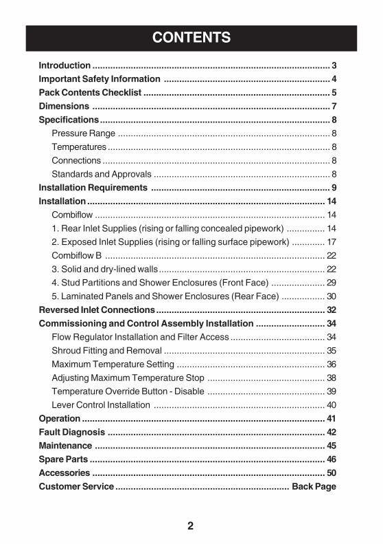
CONTENTS
Introduction ............................................................................................. 3Important Safety Information ................................................................. 4
Pack Contents Checklist ......................................................................... 5
Dimensions ............................................................................................. 7
Specifications.......................................................................................... 8Pressure Range ................................................................................... 8
Temperatures ....................................................................................... 8
Connections ......................................................................................... 8
Standards and Approvals ..................................................................... 8
Installation Requirements ...................................................................... 9
Installation ............................................................................................. 14
Combiflow .......................................................................................... 14
1. Rear Inlet Supplies (rising or falling concealed pipework) ............... 14
2. Exposed Inlet Supplies (rising or falling surface pipework) ............. 17
Combiflow B ...................................................................................... 22
3. Solid and dry-lined walls................................................................. 22
4. Stud Partitions and Shower Enclosures (Front Face) ..................... 29
5. Laminated Panels and Shower Enclosures (Rear Face) ................. 30
Reversed Inlet Connections.................................................................. 32
Commissioning and Control Assembly Installation ........................... 34Flow Regulator Installation and Filter Access ..................................... 34
Shroud Fitting and Removal ............................................................... 35
Maximum Temperature Setting .......................................................... 36
Adjusting Maximum Temperature Stop .............................................. 38
Temperature Override Button - Disable .............................................. 39
Lever Control Installation ................................................................... 40
Operation ............................................................................................... 41
Fault Diagnosis ..................................................................................... 42Maintenance .......................................................................................... 45
Spare Parts ............................................................................................ 46
Accessories ........................................................................................... 50
Customer Service .................................................................... Back Page
3
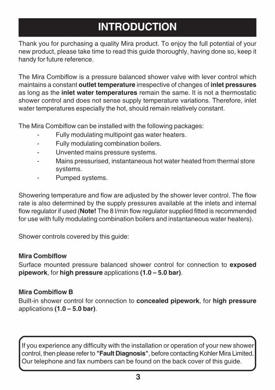
INTRODUCTIONThank you for purchasing a quality Mira product. To enjoy the full potential of yournew product, please take time to read this guide thoroughly, having done so, keep ithandy for future reference.
The Mira Combiflow is a pressure balanced shower valve with lever control whichmaintains a constant outlet temperature irrespective of changes of inlet pressuresas long as the inlet water temperatures remain the same. It is not a thermostaticshower control and does not sense supply temperature variations. Therefore, inletwater temperatures especially the hot, should remain relatively constant.
The Mira Combiflow can be installed with the following packages:- Fully modulating multipoint gas water heaters.- Fully modulating combination boilers.- Unvented mains pressure systems.- Mains pressurised, instantaneous hot water heated from thermal store
systems.- Pumped systems.
Showering temperature and flow are adjusted by the shower lever control. The flowrate is also determined by the supply pressures available at the inlets and internalflow regulator if used (Note! The 8 l/min flow regulator supplied fitted is recommendedfor use with fully modulating combination boilers and instantaneous water heaters).
Shower controls covered by this guide:
Mira CombiflowSurface mounted pressure balanced shower control for connection to exposedpipework, for high pressure applications (1.0 – 5.0 bar).
Mira Combiflow BBuilt-in shower control for connection to concealed pipework, for high pressureapplications (1.0 – 5.0 bar).
If you experience any difficulty with the installation or operation of your new showercontrol, then please refer to "Fault Diagnosis", before contacting Kohler Mira Limited.Our telephone and fax numbers can be found on the back cover of this guide.
4
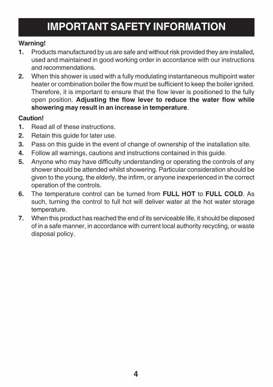
IMPORTANT SAFETY INFORMATIONWarning!1. Products manufactured by us are safe and without risk provided they are installed,
used and maintained in good working order in accordance with our instructionsand recommendations.
2. When this shower is used with a fully modulating instantaneous multipoint waterheater or combination boiler the flow must be sufficient to keep the boiler ignited.Therefore, it is important to ensure that the flow lever is positioned to the fullyopen position. Adjusting the flow lever to reduce the water flow whileshowering may result in an increase in temperature.
Caution!1. Read all of these instructions.2. Retain this guide for later use.3. Pass on this guide in the event of change of ownership of the installation site.4. Follow all warnings, cautions and instructions contained in this guide.5. Anyone who may have difficulty understanding or operating the controls of any
shower should be attended whilst showering. Particular consideration should begiven to the young, the elderly, the infirm, or anyone inexperienced in the correctoperation of the controls.
6. The temperature control can be turned from FULL HOT to FULL COLD. Assuch, turning the control to full hot will deliver water at the hot water storagetemperature.
7. When this product has reached the end of its serviceable life, it should be disposedof in a safe manner, in accordance with current local authority recycling, or wastedisposal policy.
5
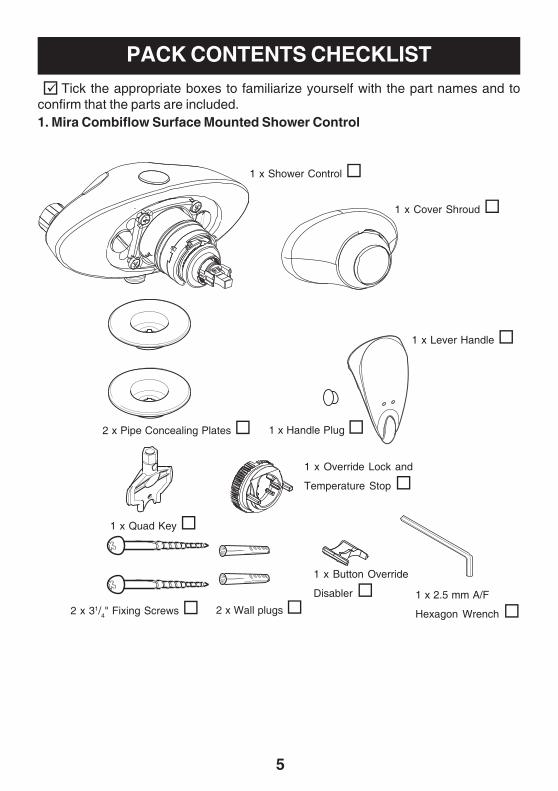
PACK CONTENTS CHECKLIST Tick the appropriate boxes to familiarize yourself with the part names and toconfirm that the parts are included.1. Mira Combiflow Surface Mounted Shower Control
1 x Shower Control
2 x Pipe Concealing Plates
1 x Quad Key
1 x 2.5 mm A/F
Hexagon Wrench 2 x 31/4" Fixing Screws 2 x Wall plugs
1 x Handle Plug
1 x Lever Handle
1 x Cover Shroud
1 x Override Lock and
Temperature Stop
1 x Button Override
Disabler
6
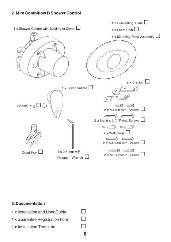
2. Mira Combiflow B Shower Control
3. Documentation
1 x Installation and User Guide
1 x Guarantee Registration Form
1 x Installation Template
1 x Shower Control with Building-in Cover
2 x M4 x 30 mm Screws
2 x No. 8 x 11/2" Fixing Screws
2 x Wall plugs
2 x M4 x 8 mm Screws
1 x 2.5 mm A/F
Hexagon Wrench
Handle Plug
1 x Concealing Plate
1 x Foam Seal
1 x Mounting Plate Assembly
1 x Lever Handle
Quad Key
2 x Bracket
2 x M5 x 25mm Screws
7
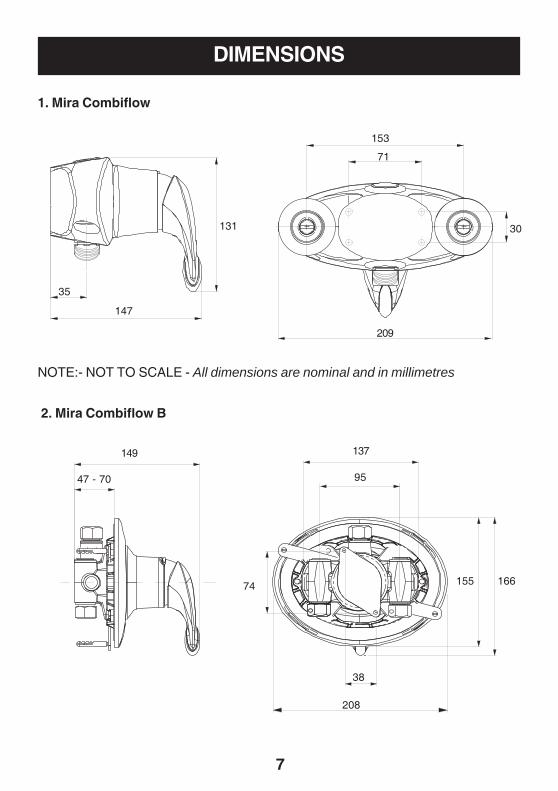
DIMENSIONS
1. Mira Combiflow
NOTE:- NOT TO SCALE - All dimensions are nominal and in millimetres
147
131
153
209
149
74 166
35
208
2. Mira Combiflow B
71
30
47 - 70
137
95
38
155
8
Mira Combiflow and Mira Combiflow BPressure Range
Minimum maintained pressure: 1.0 bar
Maximum maintained pressure: 5.0 bar
Maximum static pressure: 10 bar.
Note! For optimum performance, the initial supply pressures should be nominallyequal.
Temperatures
Hot and cold water supply temperatures MUST remain relatively constant.
Maximum hot water temperature: 80°C.
Ideally the hot water temperature should never exceed 65°C. A water temperature of60°C is considered sufficient to meet all normal requirements and will minimize thedeposition of scale in hard water areas.
Connections
Inlet15 mm Compression (Combiflow B).15 mm Compression (Combiflow).
Outlet1/
2'' BSP male (Combiflow).
15 mm Compression (Combiflow B).
Standards and Approvals
1. Designed to be used within systems in line with BS6700.
2. BS 6700 recommends that the temperature of stored water should never exceed65 °C. A stored water temperature of 60 °C is considered sufficient to meet allnormal requirements and will minimise the deposition of scale in hard water areas.
SPECIFICATIONS
9
INSTALLATION REQUIREMENTSRead the section 'Important Safety Information' first.Installation must be carried out in accordance with these instructions, and must beconducted by designated, qualified and competent personnel.1. Installations must comply with UK Water Regulations/ Bye-laws (Scotland), and
Building and Plumbing Regulations in force at the time of installation.2. Layout and sizing of pipework must be such that when other services are used,
pressures at the shower mixer control inlets do not fall below the recommendedminimum (1 bar). The pressure balancing performance is impaired below 1 bar.When fitted with some heater appliances the minimum maintained pressure mayneed to be above 1 bar, to keep the flow rate sufficiently high in order to ensurethe gas flame stays lit.
3. The Mira Combiflow is not suitable for installation as part of a gravity-fed plumbingsystem (i.e. in conjunction with a hot water cylinder and cold water storage cistern),unless used in conjunction with an inlet pump producing a maintained pressureof at least 1 bar.
4. When used with a fully modulating multipoint or combination boiler above 5 barmaintained pressure, a pressure reducing valve will be necessary. Forinformation on measuring system pressures refer to section: 'InstallationRequirements, Measuring System Pressures'. For further information onpressure reducing valves consult your local plumbing stockist.
5. Supply pipes MUST be flushed to clear debris before connecting the showercontrol.
6. Conveniently situated isolating valves are recommended to be fitted for servicingpurposes.
7. If the shower control is to be used with a fully modulating multipoint water heater,fully modulating combination boiler, thermal store or unvented system anexpansion vessel must be fitted to accommodate the expansion of water in thedomestic hot water supply (this may already be part of the system, check thedetails on the boiler/heater or contact the boiler/heater manufacturer).
8. No form of outlet flow control should be fitted, only Mira recommended fittingsshould be used in the outlet pipework.
9. Do not install the product in a position in which service access is restricted.10. Do not fit any form of flow control in the shower outlet.11. Do not use excessive force when making connections.12. Do not install the product in a position where it could become frozen.
10
Typical Suitable Installations
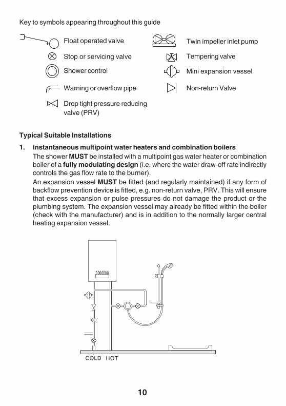
1. Instantaneous multipoint water heaters and combination boilersThe shower MUST be installed with a multipoint gas water heater or combinationboiler of a fully modulating design (i.e. where the water draw-off rate indirectlycontrols the gas flow rate to the burner).An expansion vessel MUST be fitted (and regularly maintained) if any form ofbackflow prevention device is fitted, e.g. non-return valve, PRV. This will ensurethat excess expansion or pulse pressures do not damage the product or theplumbing system. The expansion vessel may already be fitted within the boiler(check with the manufacturer) and is in addition to the normally larger centralheating expansion vessel.
HOTCOLD
Float operated valve
Non-return Valve
Drop tight pressure reducingvalve (PRV)
Shower control
Stop or servicing valve
Warning or overflow pipe
Twin impeller inlet pump
Tempering valve
Mini expansion vessel
Key to symbols appearing throughout this guide
11
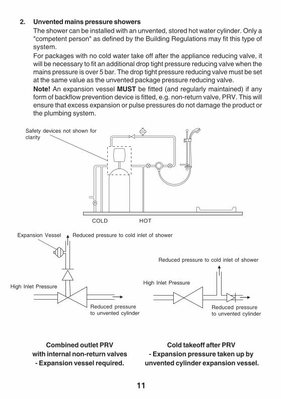
HOTCOLD
Combined outlet PRVwith internal non-return valves- Expansion vessel required.
Cold takeoff after PRV- Expansion pressure taken up by
unvented cylinder expansion vessel.
Reduced pressure to cold inlet of shower
Reduced pressureto unvented cylinder
High Inlet Pressure
Reduced pressure to cold inlet of shower
Expansion Vessel
Safety devices not shown forclarity
2. Unvented mains pressure showersThe shower can be installed with an unvented, stored hot water cylinder. Only a"competent person" as defined by the Building Regulations may fit this type ofsystem.For packages with no cold water take off after the appliance reducing valve, itwill be necessary to fit an additional drop tight pressure reducing valve when themains pressure is over 5 bar. The drop tight pressure reducing valve must be setat the same value as the unvented package pressure reducing valve.Note! An expansion vessel MUST be fitted (and regularly maintained) if anyform of backflow prevention device is fitted, e.g. non-return valve, PRV. This willensure that excess expansion or pulse pressures do not damage the product orthe plumbing system.
High Inlet Pressure
Reduced pressureto unvented cylinder
12
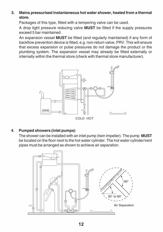
3. Mains pressurised instantaneous hot water shower, heated from a thermalstore.Packages of this type, fitted with a tempering valve can be used.A drop tight pressure reducing valve MUST be fitted if the supply pressuresexceed 5 bar maintained.An expansion vessel MUST be fitted (and regularly maintained) if any form ofbackflow prevention device is fitted, e.g. non-return valve, PRV. This will ensurethat excess expansion or pulse pressures do not damage the product or theplumbing system. The expansion vessel may already be fitted externally orinternally within the thermal store (check with thermal store manufacturer).
COLD HOT
4. Pumped showers (inlet pumps)The shower can be installed with an inlet pump (twin impeller). The pump MUSTbe located on the floor next to the hot water cylinder. The hot water cylinder/ventpipes must be arranged as shown to achieve air separation.
90°
30° to 60°
Air Separation
13
Measuring System Pressures
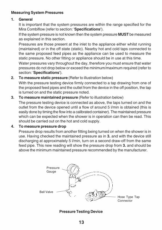
1. GeneralIt is important that the system pressures are within the range specified for theMira Combiflow (refer to section: 'Specifications').If the system pressure is not known then the system pressure MUST be measuredas explained in this section.Pressures are those present at the inlet to the appliance either whilst running(maintained) or in the off state (static). Nearby hot and cold taps connected tothe same proposed feed pipes as the appliance can be used to measure thestatic pressure. No other fitting or appliance should be in use at this time.Water pressures vary throughout the day, therefore you must ensure that waterpressures do not drop below or exceed the minimum/maximum required (refer tosection: 'Specifications').
2. To measure static pressure (Refer to illustration below)With the pressure testing device firmly connected to a tap drawing from one ofthe proposed feed pipes and the outlet from the device in the off position, the tapis turned on and the static pressure noted.
3. To measure maintained pressure (Refer to illustration below)The pressure testing device is connected as above, the taps turned on and theoutlet from the device opened until a flow of around 5 l/min is obtained (this iseasily done by timing the flow into a calibrated container). The maintained pressurewhich can be expected when the shower is in operation can then be read. Thisshould be carried out on the hot and cold supply.
4. To measure pressure dropPressure drop results from another fitting being turned on when the shower is inuse. Having checked the maintained pressure as in 3. and with the device stilldischarging at approximately 5 l/min, turn on a second draw-off from the samefeed pipe. This new reading will show the pressure drop from 3. and should beabove the minimum maintained pressure recommended by the manufacturer.
PressureGauge
Hose Type TapConnector
Ball Valve
Pressure Testing Device
14
INSTALLATIONCombiflow
1. Rear Inlet Supplies (rising or falling concealed pipework)
Read the section 'Installation Requirements' first.
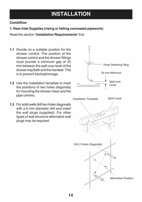
1.1 Decide on a suitable position for theshower control. The position of theshower control and the shower fittingsmust provide a minimum gap of 25mm between the spill-over level of theshower tray/bath and the handset. Thisis to prevent backsiphonage.
1.2 Use the installation template to markthe positions of two holes diagonallyfor mounting the shower mixer and thepipe centres.
1.3 For solid walls drill two holes diagonallywith a 6 mm diameter drill and insertthe wall plugs (supplied). For othertypes of wall structure alternative wallplugs may be required.
Hose Retaining Ring
25 mm Minimum
Spill-overLevel
Spirit LevelInstallation Template
Alternative Position
Drill 2 Holes Diagonally
15
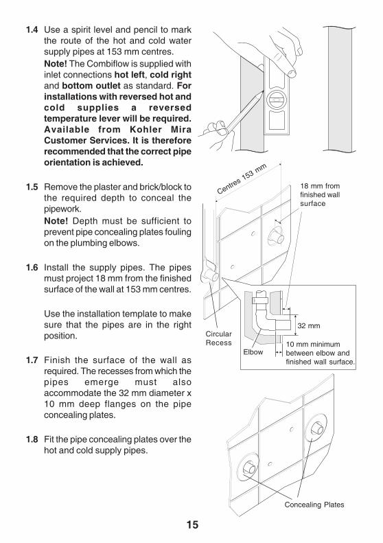
1.4 Use a spirit level and pencil to markthe route of the hot and cold watersupply pipes at 153 mm centres.Note! The Combiflow is supplied withinlet connections hot left, cold rightand bottom outlet as standard. Forinstallations with reversed hot andcold supplies a reversedtemperature lever will be required.Available from Kohler MiraCustomer Services. It is thereforerecommended that the correct pipeorientation is achieved.
1.5 Remove the plaster and brick/block tothe required depth to conceal thepipework.Note! Depth must be sufficient toprevent pipe concealing plates foulingon the plumbing elbows.
1.6 Install the supply pipes. The pipesmust project 18 mm from the finishedsurface of the wall at 153 mm centres.
Use the installation template to makesure that the pipes are in the rightposition.
1.7 Finish the surface of the wall asrequired. The recesses from which thepipes emerge must alsoaccommodate the 32 mm diameter x10 mm deep flanges on the pipeconcealing plates.
1.8 Fit the pipe concealing plates over thehot and cold supply pipes.
18 mm fromfinished wallsurface
Centres 153 m
m
Concealing Plates
32 mm
10 mm minimumbetween elbow andfinished wall surface.
CircularRecess
Elbow
16
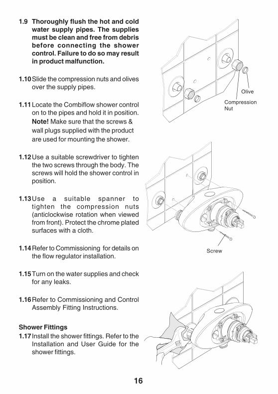
1.9 Thoroughly flush the hot and coldwater supply pipes. The suppliesmust be clean and free from debrisbefore connecting the showercontrol. Failure to do so may resultin product malfunction.
1.10Slide the compression nuts and olivesover the supply pipes.
1.11Locate the Combiflow shower controlon to the pipes and hold it in position.Note! Make sure that the screws &wall plugs supplied with the productare used for mounting the shower.
1.12Use a suitable screwdriver to tightenthe two screws through the body. Thescrews will hold the shower control inposition.
1.13Use a suitable spanner totighten the compression nuts(anticlockwise rotation when viewedfrom front). Protect the chrome platedsurfaces with a cloth.
1.14Refer to Commissioning for details onthe flow regulator installation.
1.15Turn on the water supplies and checkfor any leaks.
1.16Refer to Commissioning and ControlAssembly Fitting Instructions.
Shower Fittings1.17 Install the shower fittings. Refer to the
Installation and User Guide for theshower fittings.
Olive
CompressionNut
Screw
17
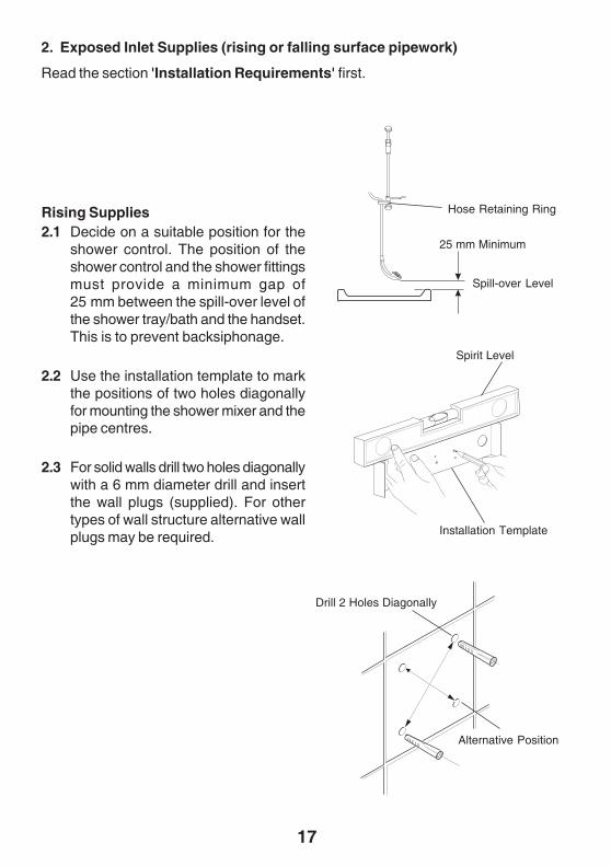
2. Exposed Inlet Supplies (rising or falling surface pipework)
Read the section 'Installation Requirements' first.
Rising Supplies2.1 Decide on a suitable position for the
shower control. The position of theshower control and the shower fittingsmust provide a minimum gap of25 mm between the spill-over level ofthe shower tray/bath and the handset.This is to prevent backsiphonage.
2.2 Use the installation template to markthe positions of two holes diagonallyfor mounting the shower mixer and thepipe centres.
2.3 For solid walls drill two holes diagonallywith a 6 mm diameter drill and insertthe wall plugs (supplied). For othertypes of wall structure alternative wallplugs may be required.
Hose Retaining Ring
25 mm Minimum
Spill-over Level
Spirit Level
Installation Template
Alternative Position
Drill 2 Holes Diagonally
18
Blanking Plugs
Inlet Nipples
Quad Key
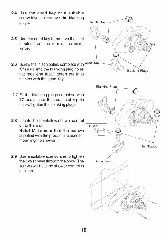
2.4 Use the quad key or a suitablescrewdriver to remove the blankingplugs.
2.5 Use the quad key to remove the inletnipples from the rear of the mixervalve.
2.6 Screw the inlet nipples, complete with'O' seals, into the blanking plug holesflat face end first.Tighten the inletnipples with the quad key.
2.7 Fit the blanking plugs complete with'O' seals, into the rear inlet nippleholes.Tighten the blanking plugs.
2.8 Locate the Combiflow shower controlon to the wall.Note! Make sure that the screwssupplied with the product are used formounting the shower.
2.9 Use a suitable screwdriver to tightenthe two screws through the body. Thescrews will hold the shower control inposition.
Blanking Plugs
Inlet Nipples
'O' Seal
Quad Key
19
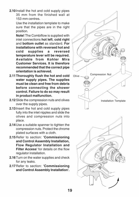
2.10 Install the hot and cold supply pipes35 mm from the finished wall at153 mm centres.Use the installation template to makesure that the pipes are in the rightposition.Note! The Combiflow is supplied withinlet connections hot left, cold rightand bottom outlet as standard. Forinstallations with reversed hot andcold supplies a reversedtemperature lever will be required.Available from Kohler MiraCustomer Services. It is thereforerecommended that the correct pipeorientation is achieved.
2.11Thoroughly flush the hot and coldwater supply pipes. The suppliesmust be clean and free from debrisbefore connecting the showercontrol. Failure to do so may resultin product malfunction.
2.12Slide the compression nuts and olivesover the supply pipes.
2.13 Insert the hot and cold supply pipesfully into the inlet nipples and slide theolives and compression nuts intoplace.
2.14Use a suitable spanner to tighten thecompression nuts. Protect the chromeplated surfaces with a cloth.
2.15Refer to section: 'Commissioningand Control Assembly Installation,Flow Regulator Installation andFilter Access' for details on the flowregulator installation.
2.16Turn on the water supplies and checkfor any leaks.
2.17Refer to section: 'Commissioningand Control Assembly Installation'.
OliveCompression Nut
Installation Template
20
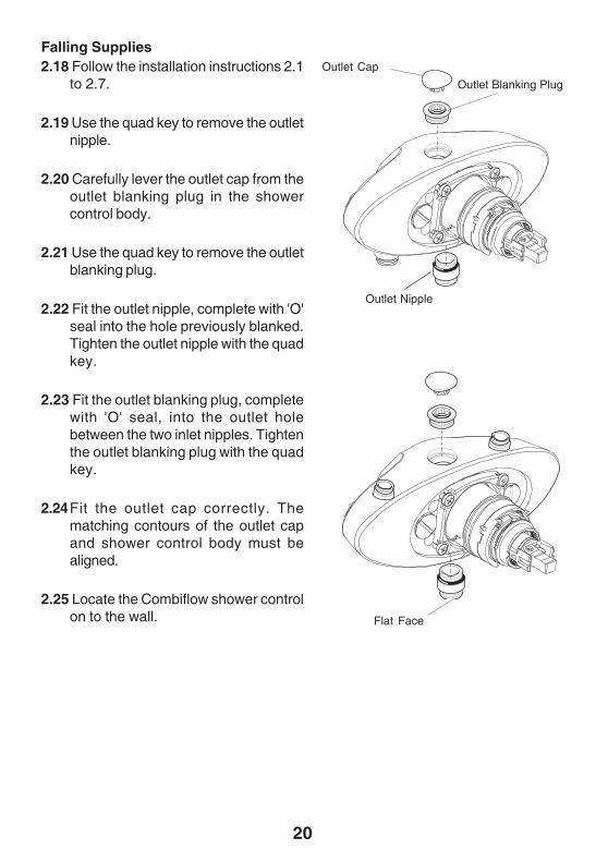
Falling Supplies2.18 Follow the installation instructions 2.1
to 2.7.
2.19 Use the quad key to remove the outletnipple.
2.20 Carefully lever the outlet cap from theoutlet blanking plug in the showercontrol body.
2.21 Use the quad key to remove the outletblanking plug.
2.22 Fit the outlet nipple, complete with 'O'seal into the hole previously blanked.Tighten the outlet nipple with the quadkey.
2.23 Fit the outlet blanking plug, completewith 'O' seal, into the outlet holebetween the two inlet nipples. Tightenthe outlet blanking plug with the quadkey.
2.24Fit the outlet cap correctly. Thematching contours of the outlet capand shower control body must bealigned.
2.25 Locate the Combiflow shower controlon to the wall.
Outlet Cap
Outlet Blanking Plug
Outlet Nipple
Flat Face
21
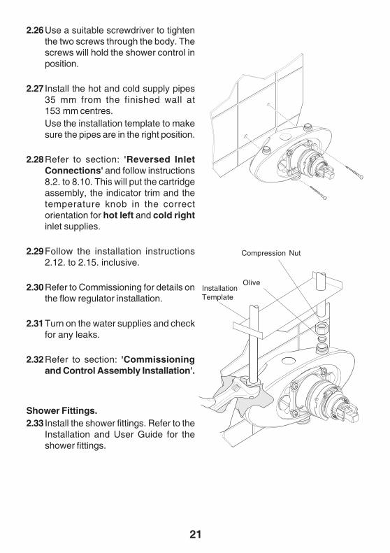
2.26Use a suitable screwdriver to tightenthe two screws through the body. Thescrews will hold the shower control inposition.
2.27 Install the hot and cold supply pipes35 mm from the finished wall at153 mm centres.Use the installation template to makesure the pipes are in the right position.
2.28Refer to section: 'Reversed InletConnections' and follow instructions8.2. to 8.10. This will put the cartridgeassembly, the indicator trim and thetemperature knob in the correctorientation for hot left and cold rightinlet supplies.
2.29Follow the installation instructions2.12. to 2.15. inclusive.
2.30Refer to Commissioning for details onthe flow regulator installation.
2.31Turn on the water supplies and checkfor any leaks.
2.32Refer to section: 'Commissioningand Control Assembly Installation'.
Shower Fittings.2.33 Install the shower fittings. Refer to the
Installation and User Guide for theshower fittings.
Compression Nut
OliveInstallationTemplate
22
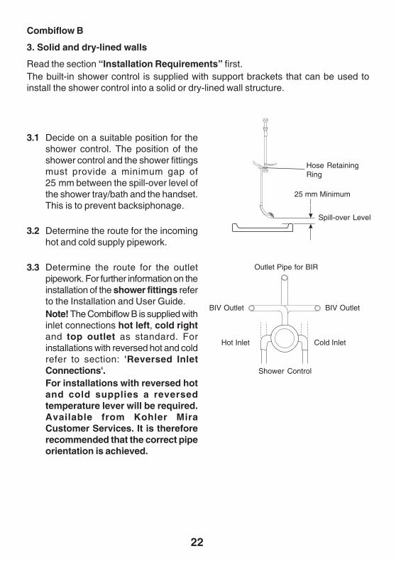
3.1 Decide on a suitable position for theshower control. The position of theshower control and the shower fittingsmust provide a minimum gap of25 mm between the spill-over level ofthe shower tray/bath and the handset.This is to prevent backsiphonage.
3.2 Determine the route for the incominghot and cold supply pipework.
3.3 Determine the route for the outletpipework. For further information on theinstallation of the shower fittings referto the Installation and User Guide.Note! The Combiflow B is supplied withinlet connections hot left, cold rightand top outlet as standard. Forinstallations with reversed hot and coldrefer to section: 'Reversed InletConnections'.For installations with reversed hotand cold supplies a reversedtemperature lever will be required.Available from Kohler MiraCustomer Services. It is thereforerecommended that the correct pipeorientation is achieved.
Combiflow B
3. Solid and dry-lined walls
Read the section “Installation Requirements” first.The built-in shower control is supplied with support brackets that can be used toinstall the shower control into a solid or dry-lined wall structure.
Hose RetainingRing
25 mm Minimum
Spill-over Level
Shower Control
Hot Inlet Cold Inlet
Outlet Pipe for BIR
BIV Outlet BIV Outlet
23
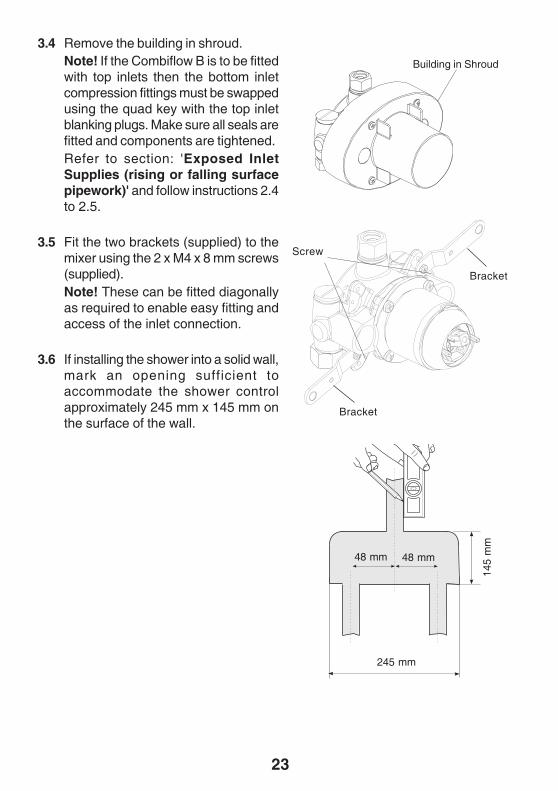
3.4 Remove the building in shroud.Note! If the Combiflow B is to be fittedwith top inlets then the bottom inletcompression fittings must be swappedusing the quad key with the top inletblanking plugs. Make sure all seals arefitted and components are tightened.Refer to section: 'Exposed InletSupplies (rising or falling surfacepipework)' and follow instructions 2.4to 2.5.
3.5 Fit the two brackets (supplied) to themixer using the 2 x M4 x 8 mm screws(supplied).Note! These can be fitted diagonallyas required to enable easy fitting andaccess of the inlet connection.
3.6 If installing the shower into a solid wall,mark an opening sufficient toaccommodate the shower controlapproximately 245 mm x 145 mm onthe surface of the wall.
145
mm
245 mm
Bracket
Bracket
Screw
Building in Shroud
48 mm 48 mm
24
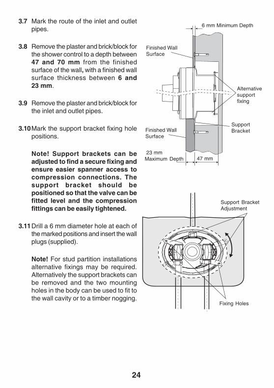
Support BracketAdjustment
Fixing Holes
6 mm Minimum Depth
Finished WallSurface
23 mmMaximum Depth 47 mm
SupportBracketFinished Wall
Surface
3.7 Mark the route of the inlet and outletpipes.
3.8 Remove the plaster and brick/block forthe shower control to a depth between47 and 70 mm from the finishedsurface of the wall, with a finished wallsurface thickness between 6 and23 mm.
3.9 Remove the plaster and brick/block forthe inlet and outlet pipes.
3.10Mark the support bracket fixing holepositions.
Note! Support brackets can beadjusted to find a secure fixing andensure easier spanner access tocompression connections. Thesupport bracket should bepositioned so that the valve can befitted level and the compressionfittings can be easily tightened.
3.11Drill a 6 mm diameter hole at each ofthe marked positions and insert the wallplugs (supplied).
Note! For stud partition installationsalternative fixings may be required.Alternatively the support brackets canbe removed and the two mountingholes in the body can be used to fit tothe wall cavity or to a timber nogging.
Alternativesupportfixing
25
Fixing Screw
Support BracketAdjustment
Alternative RearFixing
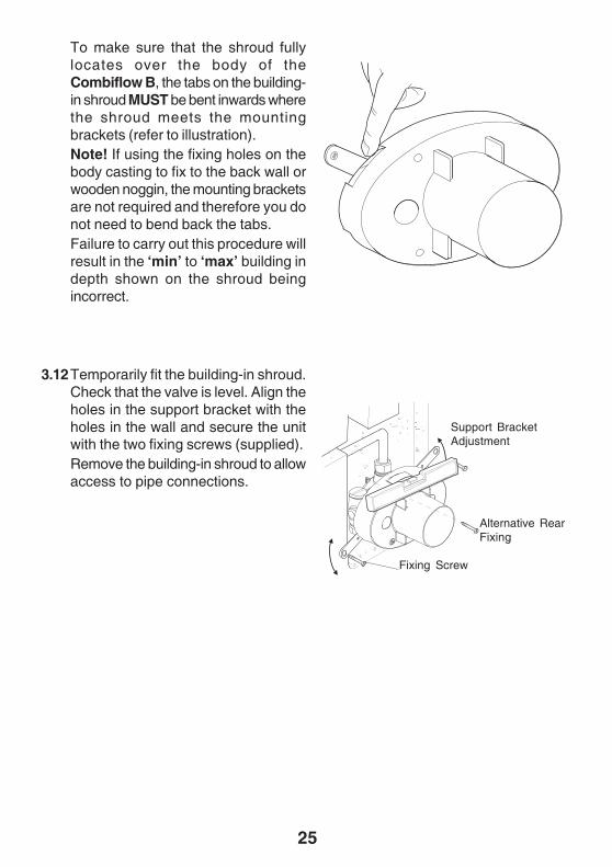
To make sure that the shroud fullylocates over the body of theCombiflow B, the tabs on the building-in shroud MUST be bent inwards wherethe shroud meets the mountingbrackets (refer to illustration).Note! If using the fixing holes on thebody casting to fix to the back wall orwooden noggin, the mounting bracketsare not required and therefore you donot need to bend back the tabs.Failure to carry out this procedure willresult in the ‘min’ to ‘max’ building indepth shown on the shroud beingincorrect.
3.12Temporarily fit the building-in shroud.Check that the valve is level. Align theholes in the support bracket with theholes in the wall and secure the unitwith the two fixing screws (supplied).Remove the building-in shroud to allowaccess to pipe connections.
26
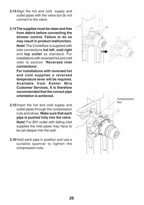
3.13Align the hot and cold supply andoutlet pipes with the valve but do notconnect to the valve.
3.14The supplies must be clean and freefrom debris before connecting theshower control. Failure to do somay result in product malfunction.Note! The Combiflow is supplied withinlet connections hot left, cold rightand top outlet as standard. Forinstallations with reversed hot and coldrefer to section: 'Reversed inletconnections'.For installations with reversed hotand cold supplies a reversedtemperature lever will be required.Available from Kohler MiraCustomer Services. It is thereforerecommended that the correct pipeorientation is achieved.
3.15 Insert the hot and cold supply andoutlet pipes through the compressionnuts and olives. Make sure that eachpipe is pushed fully into the valve.Note! For BIV outlet with falling inletsupplies the inlet pipes may have tobe set deeper into the wall.
3.16Hold each pipe in position and use asuitable spanner to tighten thecompression nuts.
CompressionNut
27
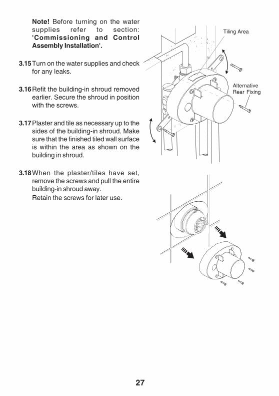
Note! Before turning on the watersupplies refer to section:'Commissioning and ControlAssembly Installation'.
3.15Turn on the water supplies and checkfor any leaks.
3.16Refit the building-in shroud removedearlier. Secure the shroud in positionwith the screws.
3.17Plaster and tile as necessary up to thesides of the building-in shroud. Makesure that the finished tiled wall surfaceis within the area as shown on thebuilding in shroud.
3.18When the plaster/tiles have set,remove the screws and pull the entirebuilding-in shroud away.Retain the screws for later use.
Tiling Area
AlternativeRear Fixing
28
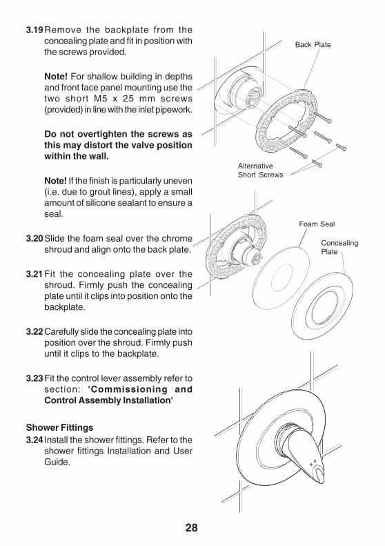
3.19Remove the backplate from theconcealing plate and fit in position withthe screws provided.
Note! For shallow building in depthsand front face panel mounting use thetwo short M5 x 25 mm screws(provided) in line with the inlet pipework.
Do not overtighten the screws asthis may distort the valve positionwithin the wall.
Note! If the finish is particularly uneven(i.e. due to grout lines), apply a smallamount of silicone sealant to ensure aseal.
3.20Slide the foam seal over the chromeshroud and align onto the back plate.
3.21Fit the concealing plate over theshroud. Firmly push the concealingplate until it clips into position onto thebackplate.
3.22Carefully slide the concealing plate intoposition over the shroud. Firmly pushuntil it clips to the backplate.
3.23Fit the control lever assembly refer tosection: 'Commissioning andControl Assembly Installation'
Shower Fittings3.24 Install the shower fittings. Refer to the
shower fittings Installation and UserGuide.
Back Plate
ConcealingPlate
AlternativeShort Screws
Foam Seal
29
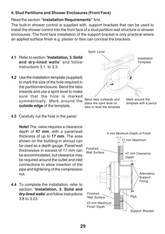
4. Stud Partitions and Shower Enclosures (Front Face)
Read the section “Installation Requirements” first.The built-in shower control is supplied with support brackets that can be used toinstall the shower control into the front face of a stud partition wall structure or showerenclosures. The front face installation of the support bracket is only practical wherean applied surface finish e.g. plaster or tiles can conceal the brackets.
4.1 Refer to section: 'Installation, 3. Solidand dry-lined walls' and followinstructions 3.1. to 3.3.
4.2 Use the installation template (supplied)to mark the size of the hole required inthe partition/enclosure. Bend the tabsinwards and use a spirit level to makesure that the hole is markedsymmetrically. Mark around theoutside edge of the template.
4.3 Carefully cut the hole in the panel.
Note! The valve requires a clearancedepth of 47 mm, with a panel/wallthickness of up to 17 mm. The areashown on the building-in shroud canbe used as a depth gauge. Panel/wallthicknesses in excess of 17 mm canbe accommodated, but clearance maybe required around the outlet and inletconnections to allow insertion of thepipe and tightening of the compressionnut.
4.4 To complete the installation, refer tosection: 'Installation, 3. Solid anddry-lined walls' and follow instructions3.8 to 3.23.
Mark around thetemplate with a pencil
6 mm Minimum Depth of Finish
FinishedWall Surface
23 mm MaximumFinish Depth
47 mm ClearanceDepth
Support Bracket
FinishedWall Surface
17 mm Maximum
Spirit Level
InstallationTemplate
Bend tabs outwards andplace the spirit level ontabs to level the template
AlternativeSupportFixing
Pipe

30
Mark through theslots in the templatewith a pencil
Spirit Level
InstallationTemplate
Bend tabs inwards andplace the spirit level ontabs to level the template
5. Laminated Panels and Shower Enclosures (Rear Face)
Read the section 'Installation Requirements' first.The built-in shower control is supplied with support brackets that can be used toinstall the shower control onto the rear face of a laminated panel or preformed showercubicle.
Note! This installation is possible witha finished wall thickness of between4 and 21 mm.
5.1 Refer to section: 'Installation, 3. Solidand dry-lined walls' and followinstructions 3.1. to 3.3.
5.2 Use the installation template (supplied)to mark the size of the hole requiredon the panel.
Bend the tabs inwards and use a spiritlevel to make sure that the hole ismarked symmetrically.
Mark through the inner slots of thetemplate.
5.3 Carefully cut the hole in the panel.
Note! The valve requires a clearancedepth of 47 mm, with a finished wallthickness of between 4 and 21 mm
5.4 Drill a 5 mm diameter hole at each ofthe marked positions.
4 mm Minimum Depth
21 mmMaximum Depth
47 mm Clearance Depth
AlternativeSupportFixing
31
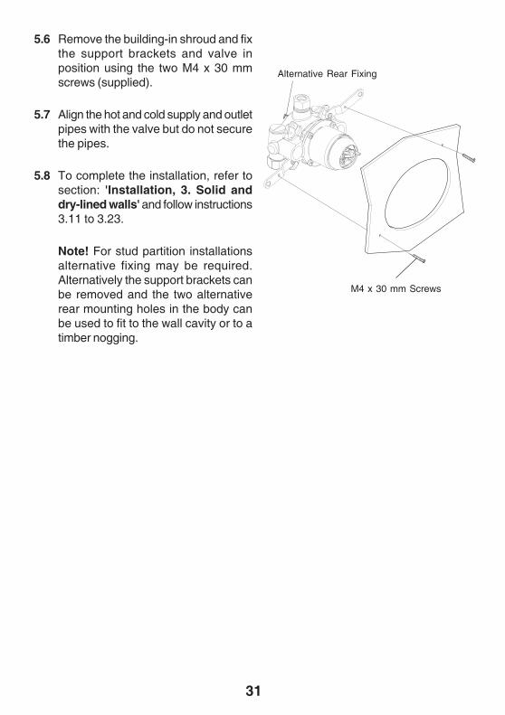
5.6 Remove the building-in shroud and fixthe support brackets and valve inposition using the two M4 x 30 mmscrews (supplied).
5.7 Align the hot and cold supply and outletpipes with the valve but do not securethe pipes.
5.8 To complete the installation, refer tosection: 'Installation, 3. Solid anddry-lined walls' and follow instructions3.11 to 3.23.
Note! For stud partition installationsalternative fixing may be required.Alternatively the support brackets canbe removed and the two alternativerear mounting holes in the body canbe used to fit to the wall cavity or to atimber nogging.
M4 x 30 mm Screws
Alternative Rear Fixing
32
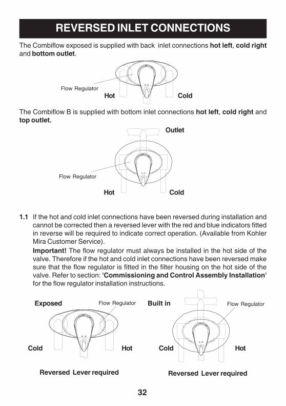
REVERSED INLET CONNECTIONSThe Combiflow exposed is supplied with back inlet connections hot left, cold rightand bottom outlet.
The Combiflow B is supplied with bottom inlet connections hot left, cold right andtop outlet.
Reversed Lever required Reversed Lever required
ColdHot
1.1 If the hot and cold inlet connections have been reversed during installation andcannot be corrected then a reversed lever with the red and blue indicators fittedin reverse will be required to indicate correct operation. (Available from KohlerMira Customer Service).Important! The flow regulator must always be installed in the hot side of thevalve. Therefore if the hot and cold inlet connections have been reversed makesure that the flow regulator is fitted in the filter housing on the hot side of thevalve. Refer to section: 'Commissioning and Control Assembly Installation'for the flow regulator installation instructions.
ColdHot
Cold Hot Cold Hot
Exposed Built in
Outlet
Flow Regulator
Flow Regulator
Flow Regulator
Flow Regulator
33
1.2 If the water supply has been connected and turned on, isolate the supplies andoperate the control lever to relieve the pressure.
1.3 Carefully pull off the control lever and shroud assembly. (refer to section:'Commissioning and Control Assembly Installation').
1.4 Remove the four cartridge retaining screws (refer to section: 'Maintenance').
1.5 Remove the upper body / flow cartridge assembly (refer to section: 'Maintenance').
1.6 Lever the pressure balancing cartridge from the body and rotate the cartridge180° and replace.Caution! Take care not to damage the two inlet seals during assembly (referto section: 'Maintenance').
1.7 Refit the upper cartridge body and make sure that the two ports are aligned withthe two ports on the pressure balancing cartridge.
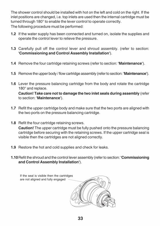
1.8 Refit the four cartridge retaining screws.Caution! The upper cartridge must be fully pushed onto the pressure balancingcartridge before securing with the retaining screws. If the upper cartridge seal isvisible then the cartridges are not aligned correctly.
1.9 Restore the hot and cold supplies and check for leaks.
1.10Refit the shroud and the control lever assembly (refer to section: 'Commissioningand Control Assembly Installation').
The shower control should be installed with hot on the left and cold on the right. If theinlet positions are changed, i.e. top inlets are used then the internal cartridge must beturned through 180° to enable the lever control to operate correctly.The following procedure must be performed:
If the seal is visible then the cartridgesare not aligned and fully engaged
34
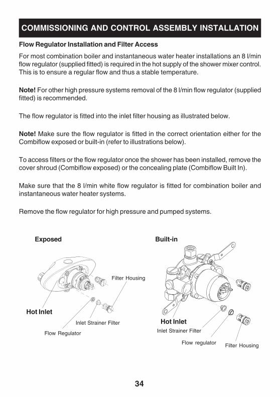
Flow Regulator Installation and Filter Access
For most combination boiler and instantaneous water heater installations an 8 l/minflow regulator (supplied fitted) is required in the hot supply of the shower mixer control.This is to ensure a regular flow and thus a stable temperature.
Note! For other high pressure systems removal of the 8 l/min flow regulator (suppliedfitted) is recommended.
The flow regulator is fitted into the inlet filter housing as illustrated below.
Note! Make sure the flow regulator is fitted in the correct orientation either for theCombiflow exposed or built-in (refer to illustrations below).
To access filters or the flow regulator once the shower has been installed, remove thecover shroud (Combiflow exposed) or the concealing plate (Combiflow Built In).
Make sure that the 8 l/min white flow regulator is fitted for combination boiler andinstantaneous water heater systems.
Remove the flow regulator for high pressure and pumped systems.
Hot InletHot Inlet
Filter Housing
Filter Housing
Flow Regulator
Flow regulator
Inlet Strainer Filter
Inlet Strainer Filter
COMMISSIONING AND CONTROL ASSEMBLY INSTALLATION
Exposed Built-in
35
Override Button at the1 O' Clock Position
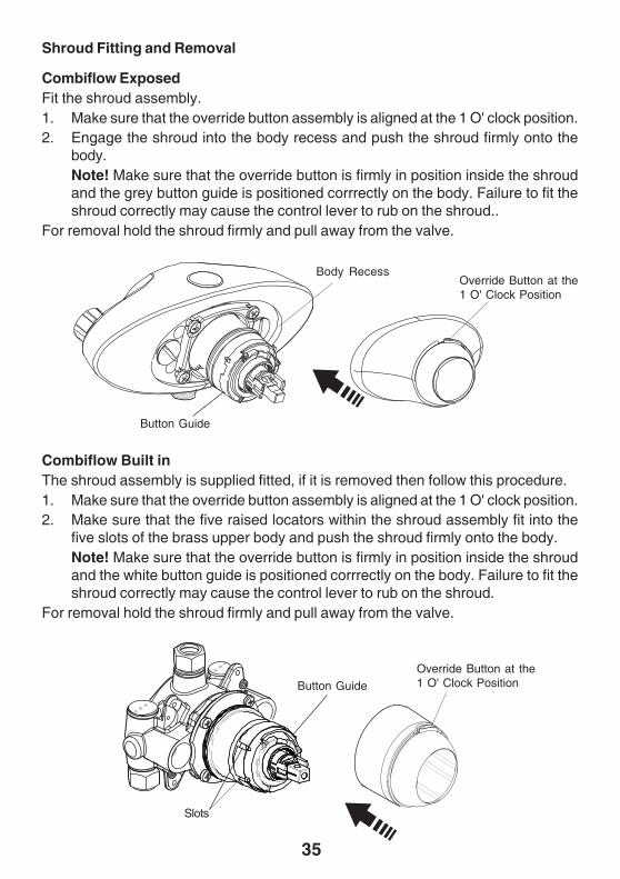
Shroud Fitting and Removal
Combiflow ExposedFit the shroud assembly.1. Make sure that the override button assembly is aligned at the 1 O' clock position.2. Engage the shroud into the body recess and push the shroud firmly onto the
body.Note! Make sure that the override button is firmly in position inside the shroudand the grey button guide is positioned corrrectly on the body. Failure to fit theshroud correctly may cause the control lever to rub on the shroud..
For removal hold the shroud firmly and pull away from the valve.
Combiflow Built inThe shroud assembly is supplied fitted, if it is removed then follow this procedure.1. Make sure that the override button assembly is aligned at the 1 O' clock position.2. Make sure that the five raised locators within the shroud assembly fit into the
five slots of the brass upper body and push the shroud firmly onto the body.Note! Make sure that the override button is firmly in position inside the shroudand the white button guide is positioned corrrectly on the body. Failure to fit theshroud correctly may cause the control lever to rub on the shroud.
For removal hold the shroud firmly and pull away from the valve.
Slots
Body Recess
Button Guide
Override Button at the1 O' Clock Position
Button Guide
36
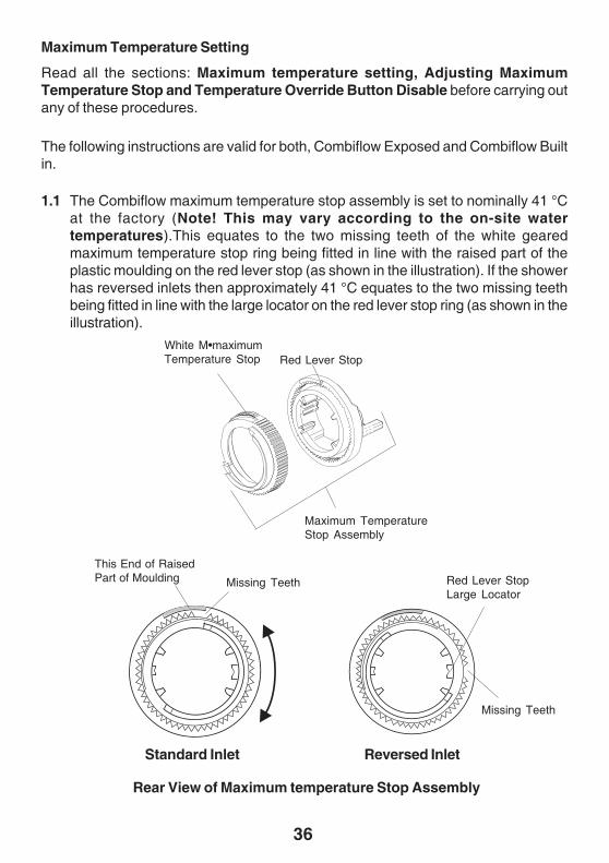
Maximum Temperature Setting
Read all the sections: Maximum temperature setting, Adjusting MaximumTemperature Stop and Temperature Override Button Disable before carrying outany of these procedures.
The following instructions are valid for both, Combiflow Exposed and Combiflow Builtin.
1.1 The Combiflow maximum temperature stop assembly is set to nominally 41 °Cat the factory (Note! This may vary according to the on-site watertemperatures).This equates to the two missing teeth of the white gearedmaximum temperature stop ring being fitted in line with the raised part of theplastic moulding on the red lever stop (as shown in the illustration). If the showerhas reversed inlets then approximately 41 °C equates to the two missing teethbeing fitted in line with the large locator on the red lever stop ring (as shown in theillustration).
White M•maximumTemperature Stop Red Lever Stop
Rear View of Maximum temperature Stop Assembly
Maximum TemperatureStop Assembly
Reversed Inlet
Missing Teeth
Missing Teeth
Standard Inlet
This End of RaisedPart of Moulding Red Lever Stop
Large Locator
37
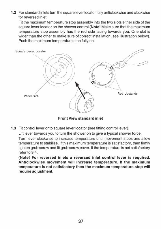
1.3 Fit control lever onto square lever locator (see fitting control lever).Lift lever towards you to turn the shower on to give a typical shower force.Turn lever clockwise to increase temperature until movement stops and allowtemperature to stabilise. If this maximum temperature is satisfactory, then firmlytighten grub screw and fit grub screw cover. If the temperature is not satisfactoryrefer to 9.4.(Note! For reversed inlets a reversed inlet control lever is required.Anticlockwise movement will increase temperature. If the maximumtemperature is not satisfactory then the maximum temperature stop willrequire adjustment.
Front View standard inlet
Square Lever Locator
1.2 For standard inlets turn the square lever locator fully anticlockwise and clockwisefor reversed inlet.Fit the maximum temperature stop assembly into the two slots either side of thesquare lever locator on the shower control (Note! Make sure that the maximumtemperature stop assembly has the red side facing towards you. One slot iswider than the other to make sure of correct installation, see illustration below).Push the maximum temperature stop fully on.
Wider SlotRed Upstands
38
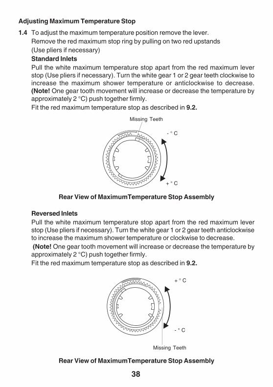
Adjusting Maximum Temperature Stop
1.4 To adjust the maximum temperature position remove the lever.Remove the red maximum stop ring by pulling on two red upstands(Use pliers if necessary)Standard InletsPull the white maximum temperature stop apart from the red maximum leverstop (Use pliers if necessary). Turn the white gear 1 or 2 gear teeth clockwise toincrease the maximum shower temperature or anticlockwise to decrease.(Note! One gear tooth movement will increase or decrease the temperature byapproximately 2 °C) push together firmly.Fit the red maximum temperature stop as described in 9.2.
- ° C
+ ° C
Missing Teeth
- ° C
+ ° C
Missing Teeth
Rear View of MaximumTemperature Stop Assembly
Reversed InletsPull the white maximum temperature stop apart from the red maximum leverstop (Use pliers if necessary). Turn the white gear 1 or 2 gear teeth anticlockwiseto increase the maximum shower temperature or clockwise to decrease. (Note! One gear tooth movement will increase or decrease the temperature byapproximately 2 °C) push together firmly.Fit the red maximum temperature stop as described in 9.2.
Rear View of MaximumTemperature Stop Assembly
39
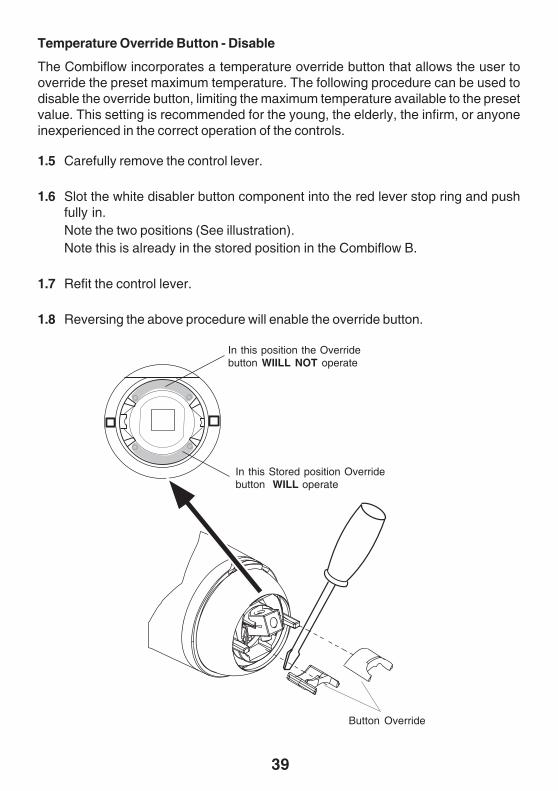
1.5 Carefully remove the control lever.
1.6 Slot the white disabler button component into the red lever stop ring and pushfully in.Note the two positions (See illustration).Note this is already in the stored position in the Combiflow B.
1.7 Refit the control lever.
1.8 Reversing the above procedure will enable the override button.
Temperature Override Button - Disable
The Combiflow incorporates a temperature override button that allows the user tooverride the preset maximum temperature. The following procedure can be used todisable the override button, limiting the maximum temperature available to the presetvalue. This setting is recommended for the young, the elderly, the infirm, or anyoneinexperienced in the correct operation of the controls.
In this position the Overridebutton WIILL NOT operate
In this Stored position Overridebutton WILL operate
Button Override
40
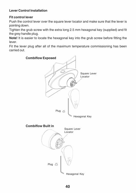
Lever Control Installation
Fit control leverPush the control lever over the square lever locator and make sure that the lever ispointing down.Tighten the grub screw with the extra long 2.5 mm hexagonal key (supplied) and fitthe grey handle plug.Note! It is easier to locate the hexagonal key into the grub screw before fitting thelever.Fit the lever plug after all of the maximum temperature commissioning has beencarried out.
Combiflow Built in
Combiflow Exposed
Square LeverLocator
Plug
Plug
Square LeverLocator
Hexagonal Key
Hexagonal Key
41
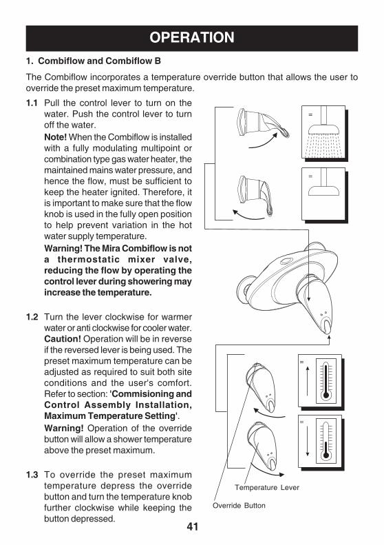
1. Combiflow and Combiflow B
The Combiflow incorporates a temperature override button that allows the user tooverride the preset maximum temperature.
OPERATION
1.1 Pull the control lever to turn on thewater. Push the control lever to turnoff the water.Note! When the Combiflow is installedwith a fully modulating multipoint orcombination type gas water heater, themaintained mains water pressure, andhence the flow, must be sufficient tokeep the heater ignited. Therefore, itis important to make sure that the flowknob is used in the fully open positionto help prevent variation in the hotwater supply temperature.Warning! The Mira Combiflow is nota thermostatic mixer valve,reducing the flow by operating thecontrol lever during showering mayincrease the temperature.
1.2 Turn the lever clockwise for warmerwater or anti clockwise for cooler water.Caution! Operation will be in reverseif the reversed lever is being used. Thepreset maximum temperature can beadjusted as required to suit both siteconditions and the user's comfort.Refer to section: 'Commisioning andControl Assembly Installation,Maximum Temperature Setting'.Warning! Operation of the overridebutton will allow a shower temperatureabove the preset maximum.
1.3 To override the preset maximumtemperature depress the overridebutton and turn the temperature knobfurther clockwise while keeping thebutton depressed.
Temperature Lever
Override Button
42
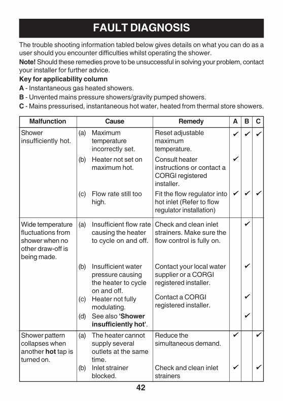
FAULT DIAGNOSISThe trouble shooting information tabled below gives details on what you can do as auser should you encounter difficulties whilst operating the shower.Note! Should these remedies prove to be unsuccessful in solving your problem, contactyour installer for further advice.Key for applicability columnA - Instantaneous gas heated showers.B - Unvented mains pressure showers/gravity pumped showers.C - Mains pressurised, instantaneous hot water, heated from thermal store showers.
Shower patterncollapses whenanother hot tap isturned on.
Reduce thesimultaneous demand.
(a) The heater cannotsupply severaloutlets at the sametime.
(b) Inlet strainerblocked.
Check and clean inletstrainers
Showerinsufficiently hot.
Wide temperaturefluctuations fromshower when noother draw-off isbeing made.
(a) Maximumtemperatureincorrectly set.
Reset adjustablemaximumtemperature.
(b) Heater not set onmaximum hot.
(c) Flow rate still toohigh.
Consult heaterinstructions or contact aCORGI registeredinstaller.
Fit the flow regulator intohot inlet (Refer to flowregulator installation)
Contact your local watersupplier or a CORGIregistered installer.
(d) See also 'Showerinsufficiently hot'.
RemedyMalfunction Cause A B C
Check and clean inletstrainers. Make sure theflow control is fully on.
(a) Insufficient flow ratecausing the heaterto cycle on and off.
(b) Insufficient waterpressure causingthe heater to cycleon and off.
(c) Heater not fullymodulating.
Contact a CORGIregistered installer.
43
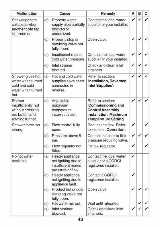
(a) Property watersupply pipe partiallyblocked orundersized.
Shower patterncollapses whenanother cold tapis turned on.
Shower gives hotwater when turnedcold and coldwater when turnedhot.
Showerinsufficiently hotwithout pressingred button androtating further.
(b) Property stop orservicing valve notfully open.
(c) Insufficient mainscold water pressure.
(a) Hot and cold watersupplies have beenconnected inreverse.
(a) Adjustablemaximumtemperatureincorrectly set.
Contact the local watersupplier or your installer.
Contact the local watersupplier or your installer.
Refer to section:'Installation, ReversedInlet Supplies'.
Refer to section:'Commissioning andControl AssemblyInstallation, MaximumTemperature Setting'.
Open valve.
(d) Inlet strainerblocked.
Check and clean inletstrainers.
Shower force toostrong.
Fit flow regulator.(c) Flow regulator notfitted.
RemedyMalfunction Cause A B C
(a) Flow control fullyopen.
Reduce the flow. Referto section: 'Operation'.
(b) Pressure above 5bar.
Contact installer to fit apressure reducing valve.
(a) Heater appliancenot igniting due toinsufficient mainspressure or flow.
(b) Heater appliancenot igniting due toappliance fault.
(c) Product hot or coldisolating valve notfully open.
No hot wateravailable.
Contact the local watersupplier or a CORGIregistered installer.
Contact a CORGIregistered installer.
Open valve.
Wait until reheated.(d) Hot water run out.Check and clean inletstrainers.
(e) Inlet strainerblocked.
44
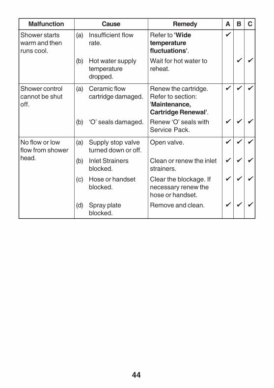
RemedyMalfunction Cause A B C
Refer to 'Widetemperaturefluctuations'.
Wait for hot water toreheat.
Renew the cartridge.Refer to section:'Maintenance,Cartridge Renewal'.
Renew ‘O’ seals withService Pack.
(a) Insufficient flowrate.
(b) Hot water supplytemperaturedropped.
(a) Ceramic flowcartridge damaged.
(b) ‘O’ seals damaged.
Shower startswarm and thenruns cool.
Shower controlcannot be shutoff.
No flow or lowflow from showerhead.
(a) Supply stop valveturned down or off.
(b) Inlet Strainersblocked.
(c) Hose or handsetblocked.
Open valve.
Clean or renew the inletstrainers.
Clear the blockage. Ifnecessary renew thehose or handset.
(d) Spray plateblocked.
Remove and clean.
45
MAINTENANCEThe Mira Combiflow is designed to be maintenance free, as such there are noserviceable parts within the flow or pressure balancing cartridge. However regularcleaning will keep the shower in pristine condition, refer to '1. Cleaning'. Strainers arefitted to the inlets of the mixer to protect the cartridge and should give many years oftrouble free showering. Filters should be checked at yearly intervals and cleaned orreplaced to maintain optimum shower performance. Refer to section: 'Commissioningand Control Assembly Installation, Flow Regulator Installation' for details on theinlet filter location.
1. CleaningMany household cleaners contain abrasive and chemical substances, and should notbe used for cleaning plated or plastic fittings. These finishes should be cleaned witha mild washing up detergent or soap solution, and then wiped dry using a soft cloth.
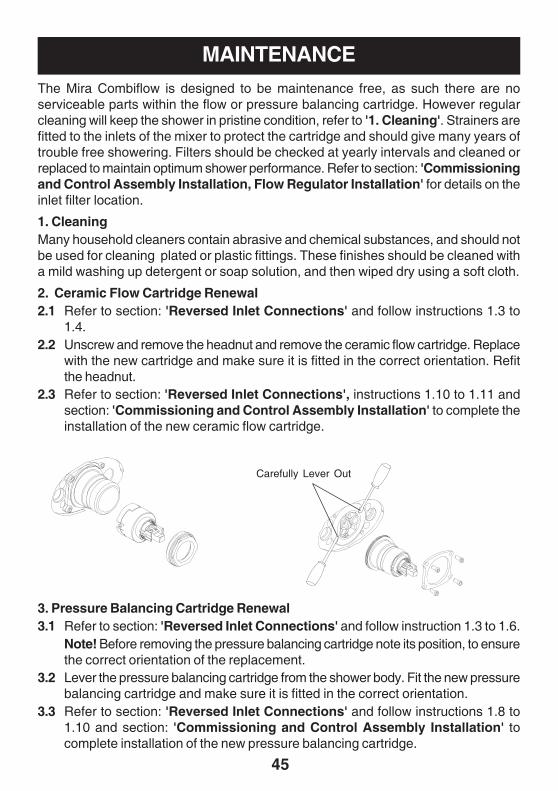
2. Ceramic Flow Cartridge Renewal2.1 Refer to section: 'Reversed Inlet Connections' and follow instructions 1.3 to
1.4.2.2 Unscrew and remove the headnut and remove the ceramic flow cartridge. Replace
with the new cartridge and make sure it is fitted in the correct orientation. Refitthe headnut.
2.3 Refer to section: 'Reversed Inlet Connections', instructions 1.10 to 1.11 andsection: 'Commissioning and Control Assembly Installation' to complete theinstallation of the new ceramic flow cartridge.
3. Pressure Balancing Cartridge Renewal3.1 Refer to section: 'Reversed Inlet Connections' and follow instruction 1.3 to 1.6.
Note! Before removing the pressure balancing cartridge note its position, to ensurethe correct orientation of the replacement.
3.2 Lever the pressure balancing cartridge from the shower body. Fit the new pressurebalancing cartridge and make sure it is fitted in the correct orientation.
3.3 Refer to section: 'Reversed Inlet Connections' and follow instructions 1.8 to1.10 and section: 'Commissioning and Control Assembly Installation' tocomplete installation of the new pressure balancing cartridge.
Carefully Lever Out
46
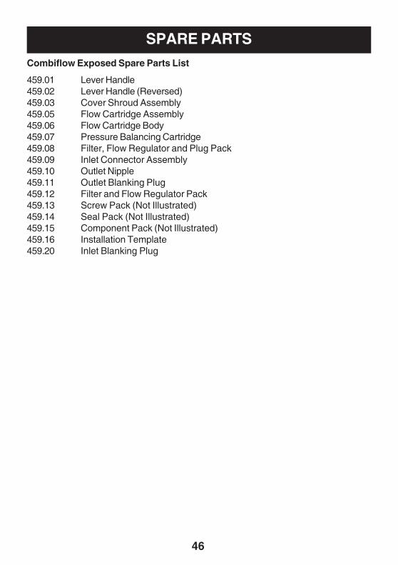
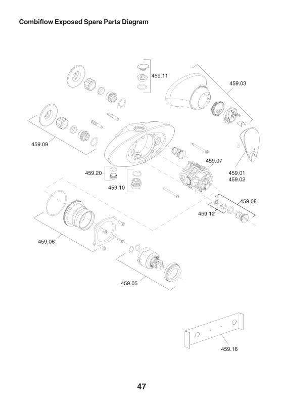
Combiflow Exposed Spare Parts List
459.01 Lever Handle459.02 Lever Handle (Reversed)459.03 Cover Shroud Assembly459.05 Flow Cartridge Assembly459.06 Flow Cartridge Body459.07 Pressure Balancing Cartridge459.08 Filter, Flow Regulator and Plug Pack459.09 Inlet Connector Assembly459.10 Outlet Nipple459.11 Outlet Blanking Plug459.12 Filter and Flow Regulator Pack459.13 Screw Pack (Not Illustrated)459.14 Seal Pack (Not Illustrated)459.15 Component Pack (Not Illustrated)459.16 Installation Template459.20 Inlet Blanking Plug
SPARE PARTS
47
Combiflow Exposed Spare Parts Diagram
459.03459.11
459.01459.02
459.08
459.12
459.10
459.07
459.20
459.16
459.09
459.06
459.05
48
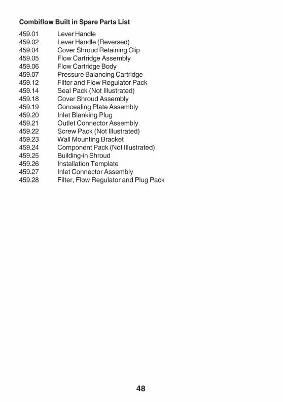
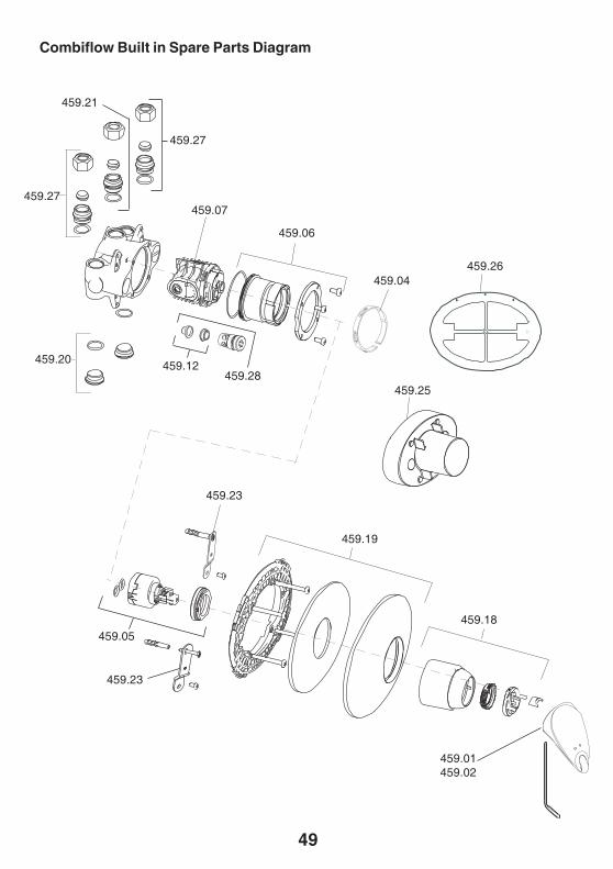
Combiflow Built in Spare Parts List
459.01 Lever Handle459.02 Lever Handle (Reversed)459.04 Cover Shroud Retaining Clip459.05 Flow Cartridge Assembly459.06 Flow Cartridge Body459.07 Pressure Balancing Cartridge459.12 Filter and Flow Regulator Pack459.14 Seal Pack (Not Illustrated)459.18 Cover Shroud Assembly459.19 Concealing Plate Assembly459.20 Inlet Blanking Plug459.21 Outlet Connector Assembly459.22 Screw Pack (Not Illustrated)459.23 Wall Mounting Bracket459.24 Component Pack (Not Illustrated)459.25 Building-in Shroud459.26 Installation Template459.27 Inlet Connector Assembly459.28 Filter, Flow Regulator and Plug Pack
49
Combiflow Built in Spare Parts Diagram
459.18
459.01459.02
459.19
459.05
459.27
459.20 459.12
459.04
459.06
459.26
459.25
459.07
459.23
459.23
459.27
459.21
459.28
50
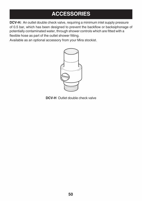
ACCESSORIESDCV-H: An outlet double check valve, requiring a minimum inlet supply pressureof 0.5 bar, which has been designed to prevent the backflow or backsiphonage ofpotentially contaminated water, through shower controls which are fitted with aflexible hose as part of the outlet shower fitting.Available as an optional accessory from your Mira stockist.
DCV-H Outlet double check valve

51
NOTES
52P4479/2 © Kohler Mira Limited, July 2005
Mira ShowersKohler Mira LtdCromwell Road,Cheltenham GL52 5EP.
Mira is a registered trade mark ofKohler Mira Limited.
The company reserves the right to alterproduct specifications without notice.
www.mirashowers.com
CUSTOMER SERVICESpare PartsWe maintain an extensive stock of spares, and aim to havefunctional parts available for ten years from the date of finalmanufacture of the product.Spares can be purchased from approved stockists ormerchants (locations on request) or direct from CustomerServices.Spares direct will normally be despatched within two workingdays. Payment can be made by Visa or Mastercard at thetime of ordering. Should payment by cheque be preferred apro-forma invoice will be sent.Note! In the interests of safety, spares requiring exposureto mains voltages can only be sent to competent persons.
ServiceOur Service Force is available to provide a quality serviceat a reasonable cost. You will have the assurance of a Miratrained engineer/agent, genuine Mira spares, and a 12 monthguarantee on the repair.Payment should be made directly to the ServiceEngineer/Agent, using Visa, Mastercard or a chequesupported by a banker’s card.
To contact usEngland, Scotland & WalesMira Showers Customer ServicesTelephone: 0870 241 08888:30 am to 5:00 pm Working days (4:30 pm Friday)8:30 am to 12.30 pm SaturdayE-mail: [email protected]: 01242 282595By Post: Cromwell Road
CheltenhamGloucestershireGL52 5EP
Northern IrelandWm H Leech & Son LtdTelephone: 028 9044 9257 – Mon to Fri 9 am-5pmFax: 028 9044 9234 – 24 hoursPost: Maryland Industrial Estate
Ballygowan RoadMoneyreagh, Co DownBT23 6BL
Republic of IrelandModern Plant LtdTelephone: 01 4591344 – Mon to Fri 9am to 5pmFax: Dublin 01 4592329 – 24 hoursPost: Otter House
Naas RoadClondalkinDublin 22
Guarantee of QualityMira Showers guarantee your product against any defect inmaterials or workmanship for the period shown in theGuarantee Registration Document included with your shower.Alternatively, to confirm the applicable guarantee periodplease contact Customer Services.To validate the guarantee, please return your completedregistration card.Within the guarantee period we will resolve defects, free ofcharge, by repairing or replacing parts or modules as wemay choose.To be free of charge, service work must only be undertakenby Mira Showers or our approved agents in Northern Irelandand Republic of Ireland.Service under this guarantee does not affect the expirydate. The guarantee on any exchanged parts or productends when the normal product guarantee period expires.Not covered by this guarantee:Damage or defects arising from incorrect installation,improper use or lack of maintenance, including build-up oflimescale.Damage or defects if the product is taken apart, repaired ormodified by any person not authorised by Mira Showers orour approved agents.This guarantee is in addition to your statutory and otherlegal rights.
Before using your showerPlease take the time to read and understand the operatingand safety instructions detailed in this manual.
What to do if something goes wrongIf when you first use your shower it doesn’t function correctly,first contact your installer to check that installation andcommissioning are satisfactory and in accordance with theinstructions in this manual. We are on-hand to offer you oryour installer any advice you may need.Should this not resolve the difficulty, simply contact ourCustomer Services who will give every assistance, and ifnecessary arrange for our service engineer to visit.If later the performance of your shower declines, consultthis manual to see whether simple home maintenance isrequired. Please call our Customer Services to talk thedifficulty through, request service under guarantee ifapplicable, or take advantage of our comprehensiveAfter-Sales service.As part of our quality and training programme calls may berecorded or monitored.Our Customer Services Team is comprehensively trainedto provide every assistance you may need: help and advice,spare parts or a service visit.
UKASQUALITY
MANAGEMENT
003
FM 14648


