44
These instructions are to be left with the user Installation & User Guide MIRA EXCEL SHOWER CONTROL

1
These instructions are to be left with the user
Installation & User Guide
mIra ExcEl
SHOWEr cONTrOl
2
ConTenTsIntroduction .............................................................................................3
Patents and Design registration ..........................................................3Important safety Information .................................................................4Pack Contents Checklist ........................................................................5Dimensions ..............................................................................................7Specifications ..........................................................................................8Installation Requirements ....................................................................10Installation .............................................................................................12
General ...............................................................................................12Excel ...................................................................................................131. Back inlet supplies (rising or falling concealed pipework) ..............132. Exposed supplies (rising or falling surface pipework) ....................16Excel B ...............................................................................................213. Solid and dry-lined walls .................................................................214. Stud Partitions and Shower Enclosures (Front Face) ....................255. laminated Panels and Shower Enclosures (rear Face) ...............26
Reversed Inlet Connections .................................................................27Control Assembly ..................................................................................29Commissioning .....................................................................................30
1. maximum temperature setting ........................................................302. maximum Temperature Settings for reversed Inlet connections .323. Temperature override button - disable ............................................33
operation ...............................................................................................34Fault Diagnosis ......................................................................................35Maintenance ...........................................................................................39
1. cleaning .........................................................................................392. cartridge assembly - renewal .........................................................393. cartridge assembly 'O' seals/inlet strainers - renewal ....................39
spare Parts ............................................................................................40Accessories ...........................................................................................43Customer service ..................................................................................44

3
Thank you for purchasing a quality mira product. To enjoy the full potential of your new product, please take time to read this guide thoroughly, having done so, keep it handy for future reference.
The mira Excel is a Thermostatic mixer with independent selection of spray force and temperature. The Thermostatic mixer incorporates a wax capsule temperature sensing unit. This provides an almost immediate response to changes in pressures or temperature of the incoming water supplies to maintain the selected temperature. an adjustable maximum temperature stop is provided which limits the temperature to the desired level. an override button allows the user to exceed the preset maximum temperature. The flow control utilizes ceramic plate technology operating directly on the hot and cold inlets to provide precise control and isolation of the incoming water supplies. Inlet filters are fitted to protect the thermostatic control mechanism.The Mira Excel (Exposed Version) has adjustable inlets to fit pipework centres between 150 mm and 155 mm.
Mira excel: an exposed shower control for connection to wall mounted or rear entry pipework.Mira excel B: a built-in shower control for connection to concealed pipework.
Patents and Design Registration
Design registration: 3 003 921, 3 003 922Patents: GB 2 291 693
France 0 694 721(E)Germany 695 13 455.8
GuaranteeFor domestic installations, mira Showers guarantee the mira Excel against any defect in materials or workmanship for a period of 5 years from the date of purchase (shower fittings for one year).For non-domestic installations, mira Showers guarantee the mira Excel against any defect in materials or workmanship for a period of one year from the date of purchase.For terms and conditions refer to the back cover of this guide.
InTRoDuCTIon
If you experience any difficulty with the installation or operation of your new Thermostatic mixer, please refer to ‘Fault Diagnosis’, before contacting Kohler mira ltd. Our telephone and fax numbers can be found on the back cover of this guide.
4
IMPoRTAnT sAFeTy InFoRMATIonThis mira Excel is precision engineered and should give continued safe and controlled performance, provided:1. It is installed, commissioned, operated and maintained in accordance with
manufacturers recommendations.2. Periodic attention is given, when necessary, to maintain the product in good
functional order.Caution!1. read all of these instructions.2. retain this guide for later use.3. Pass on this guide in the event of change of ownership of the installation
site.4. Follow all warnings, cautions and instructions contained in this guide.5. Anyone who may have difficulty understanding or operating the controls of any
shower should be attended whilst showering. Particular consideration should be given to the young, the elderly, the infirm or anyone inexperienced in the correct operation of the controls.
6. When this product has reached the end of its serviceable life, it should be disposed of in a safe manner, in accordance with current local authority recycling, or waste disposal policy.
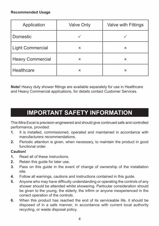
Recommended usage
application Valve Only Valve with Fittings
Domestic
light commercial
Heavy commercial
Healthcare
note! Heavy duty shower fittings are available separately for use in Healthcare and Heavy commercial applications, for details contact customer Services.
5
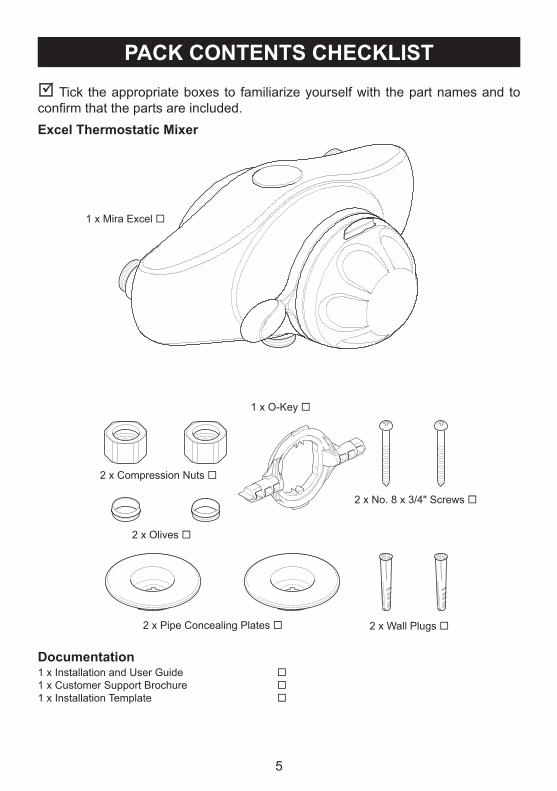
PACk ConTenTs CheCklIsT Tick the appropriate boxes to familiarize yourself with the part names and to confirm that the parts are included.excel Thermostatic Mixer
Documentation1 x Installation and User Guide 1 x customer Support Brochure 1 x Installation Template
1 x mira Excel
1 x O-Key
2 x compression Nuts
2 x Olives
2 x Pipe concealing Plates 2 x Wall Plugs
2 x No. 8 x 3/4" Screws
6
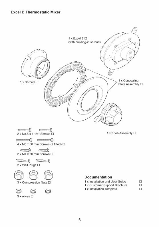
excel B Thermostatic Mixer
Documentation1 x Installation and User Guide 1 x customer Support Brochure 1 x Installation Template
1 x concealingPlate assembly
1 x Excel B (with building-in shroud)
1 x Shroud
1 x Knob assembly 2 x No.8 x 1 1/4" Screws
4 x M5 x 50 mm Screws (2 fitted)
2 x m4 x 30 mm Screws
2 x Wall Plugs
3 x compression Nuts
3 x olives
7
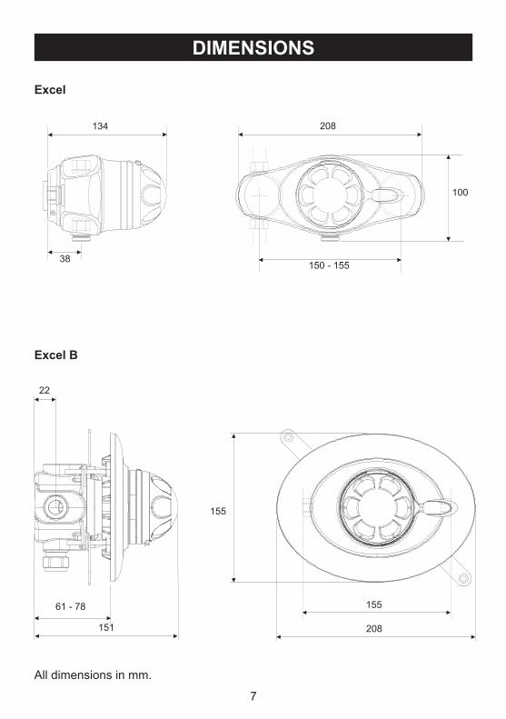
DIMensIons
excel
all dimensions in mm.
excel B
134 208
150 - 155
100
38
22
61 - 78
151
155
155
208
Documentation1 x Installation and User Guide 1 x customer Support Brochure 1 x Installation Template
8
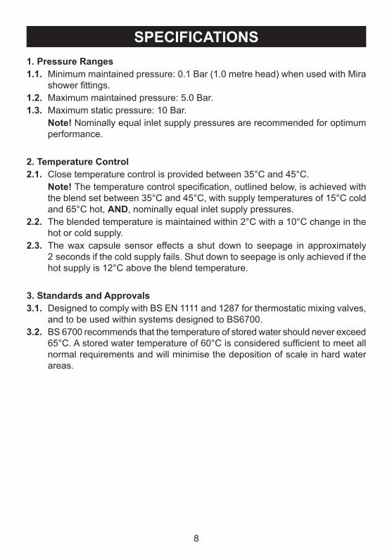
sPeCIFICATIons1. Pressure Ranges1.1. minimum maintained pressure: 0.1 Bar (1.0 metre head) when used with mira
shower fittings.1.2. maximum maintained pressure: 5.0 Bar.1.3. maximum static pressure: 10 Bar. note! Nominally equal inlet supply pressures are recommended for optimum
performance.
2. Temperature Control2.1. close temperature control is provided between 35°c and 45°c. note! The temperature control specification, outlined below, is achieved with
the blend set between 35°c and 45°c, with supply temperatures of 15°c cold and 65°c hot, AnD, nominally equal inlet supply pressures.
2.2. The blended temperature is maintained within 2°c with a 10°c change in the hot or cold supply.
2.3. The wax capsule sensor effects a shut down to seepage in approximately 2 seconds if the cold supply fails. Shut down to seepage is only achieved if the hot supply is 12°c above the blend temperature.
3. standards and Approvals3.1. Designed to comply with BS EN 1111 and 1287 for thermostatic mixing valves,
and to be used within systems designed to BS6700.3.2. BS 6700 recommends that the temperature of stored water should never exceed
65°C. A stored water temperature of 60°C is considered sufficient to meet all normal requirements and will minimise the deposition of scale in hard water areas.
9
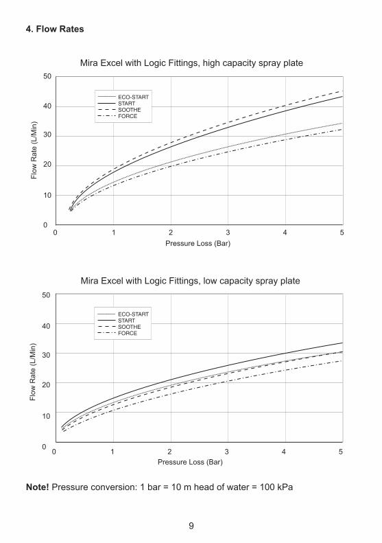
4. Flow Rates
note! Pressure conversion: 1 bar = 10 m head of water = 100 kPa
ECO-STARTSTARTSOOTHEFORCE
mira Excel with logic Fittings, high capacity spray plate
00
1 2 3 4 5Pressure loss (Bar)
Flow
rat
e (l
/min
)
10
20
30
40
50
ECO-STARTSTARTSOOTHEFORCE
mira Excel with logic Fittings, low capacity spray plate
00
1 2 3 4 5
Flow
rat
e (l
/min
)
10
20
30
40
50
Pressure loss (Bar)
10
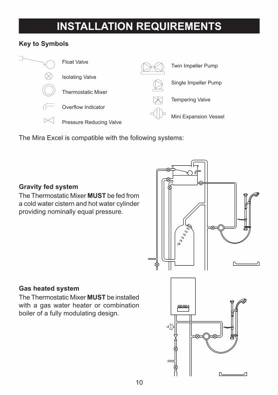
InsTAllATIon RequIReMenTs
Isolating Valve
Thermostatic mixer
Overflow Indicator
Pressure reducing Valve
Float ValveTwin Impeller Pump
Single Impeller Pump
Tempering Valve
mini Expansion Vessel
key to symbols
The mira Excel is compatible with the following systems:
Gravity fed systemThe Thermostatic mixer MusT be fed from a cold water cistern and hot water cylinder providing nominally equal pressure.
Gas heated system The Thermostatic mixer MusT be installed with a gas water heater or combination boiler of a fully modulating design.
11
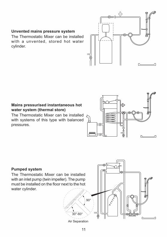
unvented mains pressure systemThe Thermostatic mixer can be installed with a unvented, stored hot water cylinder.
Mains pressurised instantaneous hot water system (thermal store)The Thermostatic mixer can be installed with systems of this type with balanced pressures.
Pumped system The Thermostatic mixer can be installed with an inlet pump (twin impeller). The pump must be installed on the floor next to the hot water cylinder.
air Separation
30°-60°
90°
12
InsTAllATIonGeneral
Installation must be carried out in accordance with these instructions, and must be conducted by designated, qualified and competent personnel.The installation must comply with the “Water Supply regulations 1999 (Water Fittings)” or any particular regulations and practices, specified by the local water company or water undertakers.note! make sure that all site requirements correspond to the information given in section: ‘Specifications’.1. The Mixer must not be installed in an area where it may freeze.2. For stud partitions alternative fixings may be required.3. Isolating valves must be installed close to the mixer for ease of maintenance.4. Pipework must be rigidly supported and avoid any strain on the connections.5. Pipework dead-legs should be kept to a minimum.6. Supply pipework layout should be arranged to minimise the effect of other outlet
usage upon the dynamic pressures at the mixer inlets.7. Inlet and outlet threaded joint connections should be made with PTFE tape or
liquid sealant. Do not use oil-based, non-setting joint compounds.8. To eliminate pipe debris it is essential that supply pipes are thoroughly flushed
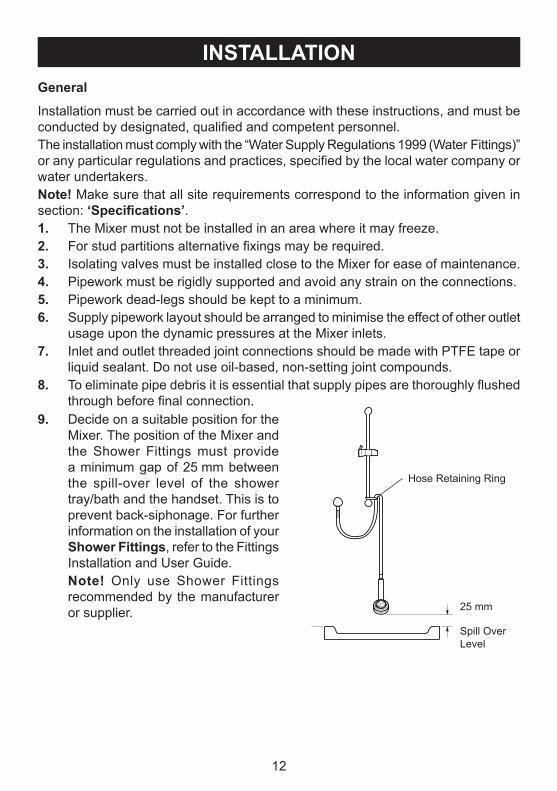
through before final connection.9. Decide on a suitable position for the
mixer. The position of the mixer and the Shower Fittings must provide a minimum gap of 25 mm between the spill-over level of the shower tray/bath and the handset. This is to prevent back-siphonage. For further information on the installation of your shower Fittings, refer to the Fittings Installation and User Guide.
note! Only use Shower Fittings recommended by the manufacturer or supplier. 25 mm
Spill Over level
Hose retaining ring
13
excel
1. Back inlet supplies (rising or falling concealed pipework)
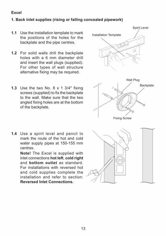
1.1 Use the installation template to mark the positions of the holes for the backplate and the pipe centres.
1.2 For solid walls drill the backplate holes with a 6 mm diameter drill and insert the wall plugs (supplied). For other types of wall structure alternative fixing may be required.
1.3 Use the two No. 8 x 1 3/4" fixing screws (supplied) to fix the backplate to the wall. make sure that the two angled fixing holes are at the bottom of the backplate.
1.4 Use a spirit level and pencil to mark the route of the hot and cold water supply pipes at 150-155 mm centres.
note! The Excel is supplied with inlet connections hot left, cold right and bottom outlet as standard. For installations with reversed hot and cold supplies complete the installation and refer to section: Reversed Inlet Connections.
Spirit level
Installation Template
I&MRepro\Orion\New Excel\P384180
Fixing Screw
Backplate
Wall Plug
14
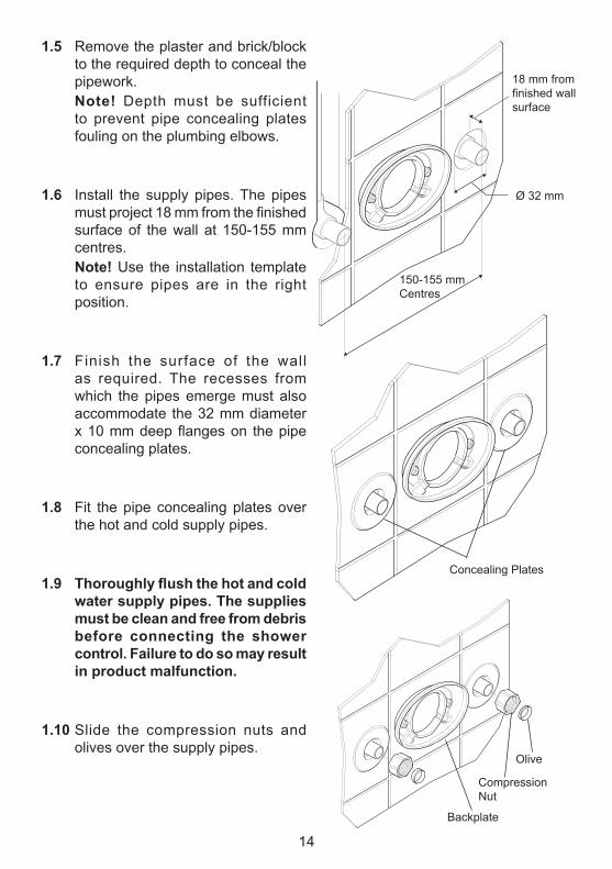
1.5 remove the plaster and brick/block to the required depth to conceal the pipework.
note! Depth must be sufficient to prevent pipe concealing plates fouling on the plumbing elbows.
1.6 Install the supply pipes. The pipes must project 18 mm from the finished surface of the wall at 150-155 mm centres.
note! Use the installation template to ensure pipes are in the right position.
1.7 Finish the surface of the wall as required. The recesses from which the pipes emerge must also accommodate the 32 mm diameter x 10 mm deep flanges on the pipe concealing plates.
1.8 Fit the pipe concealing plates over the hot and cold supply pipes.
1.9 Thoroughlyflushthehotandcoldwater supply pipes. The supplies must be clean and free from debris before connecting the shower control. Failure to do so may result in product malfunction.
1.10 Slide the compression nuts and olives over the supply pipes.
concealing Plates
18 mm fromfinished wallsurface
150-155 mmcentres
Ø 32 mm
Olive
compressionNut
Backplate
15
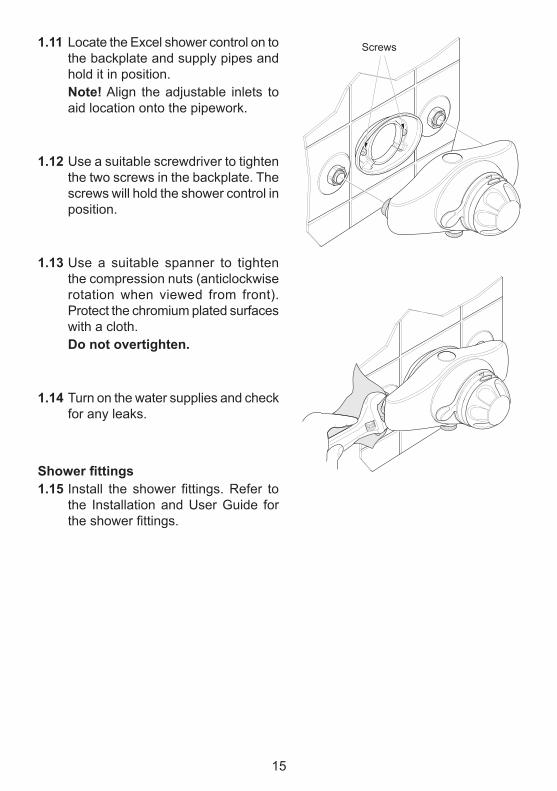
1.11 locate the Excel shower control on to the backplate and supply pipes and hold it in position.
note! align the adjustable inlets to aid location onto the pipework.
1.12 Use a suitable screwdriver to tighten the two screws in the backplate. The screws will hold the shower control in position.
1.13 Use a suitable spanner to tighten the compression nuts (anticlockwise rotation when viewed from front). Protect the chromium plated surfaces with a cloth.
Do not overtighten.
1.14 Turn on the water supplies and check for any leaks.
Showerfittings1.15 Install the shower fittings. Refer to
the Installation and User Guide for the shower fittings.
Screws
16
2. exposed supplies (rising or falling surface pipework)
Rising supplies
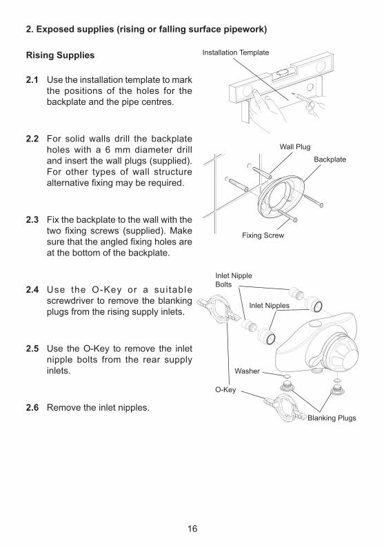
2.1 Use the installation template to mark the positions of the holes for the backplate and the pipe centres.
2.2 For solid walls drill the backplate holes with a 6 mm diameter drill and insert the wall plugs (supplied). For other types of wall structure alternative fixing may be required.
2.3 Fix the backplate to the wall with the two fixing screws (supplied). Make sure that the angled fixing holes are at the bottom of the backplate.
2.4 Use the O-Key or a sui table screwdriver to remove the blanking plugs from the rising supply inlets.
2.5 Use the O-Key to remove the inlet nipple bolts from the rear supply inlets.
2.6 remove the inlet nipples.
I&MRepro\Orion\New Excel\P384180
Fixing Screw
Backplate
Wall Plug
Installation Template
Blanking Plugs
Inlet Nipple Bolts
O-Key
Inlet Nipples
Washer
17
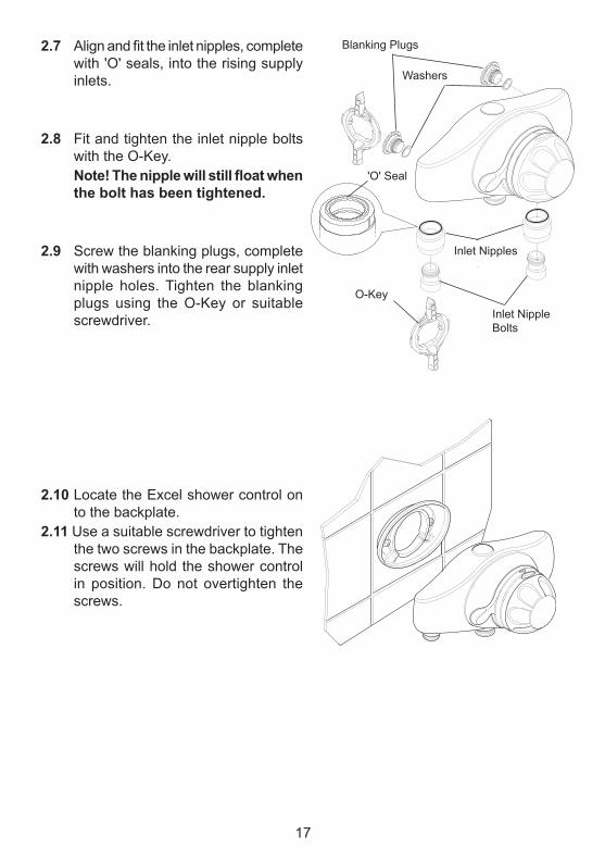
2.7 Align and fit the inlet nipples, complete with 'O' seals, into the rising supply inlets.
2.8 Fit and tighten the inlet nipple bolts with the O-Key.
Note!Thenipplewillstillfloatwhenthe bolt has been tightened.
2.9 Screw the blanking plugs, complete with washers into the rear supply inlet nipple holes. Tighten the blanking plugs using the O-Key or suitable screwdriver.
2.10 locate the Excel shower control on to the backplate.
2.11 Use a suitable screwdriver to tighten the two screws in the backplate. The screws will hold the shower control in position. Do not overtighten the screws.
Blanking Plugs
Inlet Nipples
O-Key
Inlet Nipple Bolts
'O' Seal
Washers
18
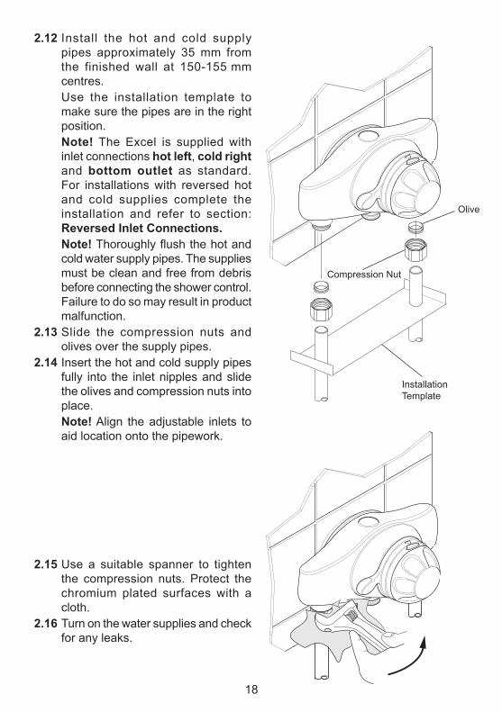
2.12 Install the hot and cold supply pipes approximately 35 mm from the finished wall at 150-155 mm centres.
Use the installation template to make sure the pipes are in the right position.
note! The Excel is supplied with inlet connections hot left, cold right and bottom outlet as standard. For installations with reversed hot and cold supplies complete the installation and refer to section: Reversed Inlet Connections.
note! Thoroughly flush the hot and cold water supply pipes. The supplies must be clean and free from debris before connecting the shower control. Failure to do so may result in product malfunction.
2.13 Slide the compression nuts and olives over the supply pipes.
2.14 Insert the hot and cold supply pipes fully into the inlet nipples and slide the olives and compression nuts into place.
note! align the adjustable inlets to aid location onto the pipework.
2.15 Use a suitable spanner to tighten the compression nuts. Protect the chromium plated surfaces with a cloth.
2.16 Turn on the water supplies and check for any leaks.
Olive
compression Nut
Installation Template
19
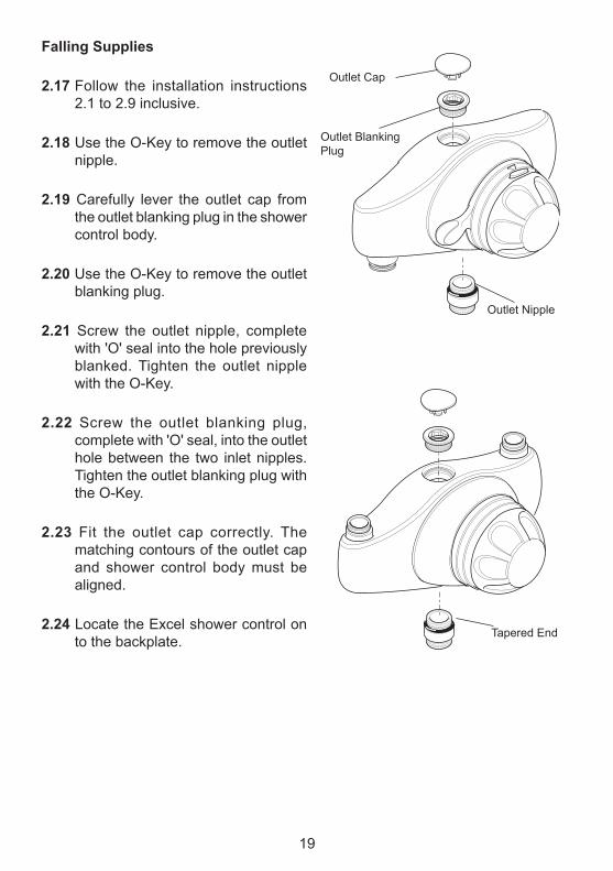
Falling supplies
2.17 Follow the installation instructions 2.1 to 2.9 inclusive.
2.18 Use the O-Key to remove the outlet nipple.
2.19 carefully lever the outlet cap from the outlet blanking plug in the shower control body.
2.20 Use the O-Key to remove the outlet blanking plug.
2.21 Screw the outlet nipple, complete with 'O' seal into the hole previously blanked. Tighten the outlet nipple with the O-Key.
2.22 Screw the outlet blanking plug, complete with 'O' seal, into the outlet hole between the two inlet nipples. Tighten the outlet blanking plug with the O-Key.
2.23 Fit the outlet cap correctly. The matching contours of the outlet cap and shower control body must be aligned.
2.24 locate the Excel shower control on to the backplate.
Tapered End
Outlet cap
Outlet Blanking Plug
Outlet Nipple
20
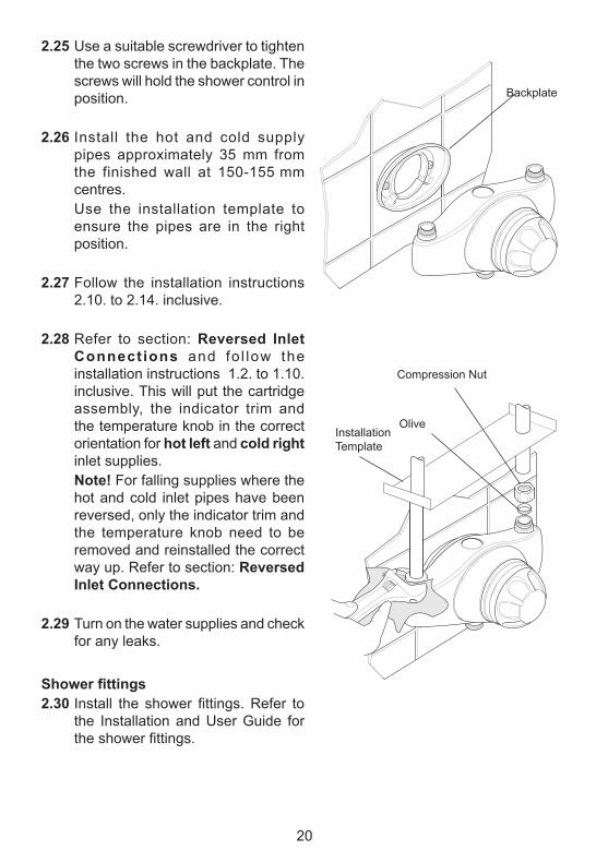
2.25 Use a suitable screwdriver to tighten the two screws in the backplate. The screws will hold the shower control in position.
2.26 Install the hot and cold supply pipes approximately 35 mm from the finished wall at 150-155 mm centres.
Use the installation template to ensure the pipes are in the right position.
2.27 Follow the installation instructions 2.10. to 2.14. inclusive.
2.28 refer to section: Reversed Inlet Connections and fo l low the installation instructions 1.2. to 1.10. inclusive. This will put the cartridge assembly, the indicator trim and the temperature knob in the correct orientation for hot left and cold right inlet supplies.
note! For falling supplies where the hot and cold inlet pipes have been reversed, only the indicator trim and the temperature knob need to be removed and reinstalled the correct way up. refer to section: Reversed Inlet Connections.
2.29 Turn on the water supplies and check for any leaks.
Showerfittings2.30 Install the shower fittings. Refer to
the Installation and User Guide for the shower fittings.
compression Nut
Olive
Backplate
Installation Template
21
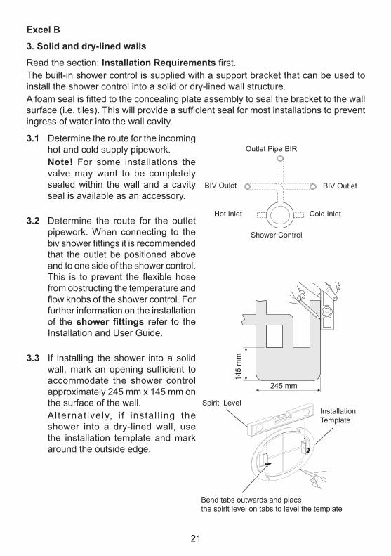
3.1 Determine the route for the incoming hot and cold supply pipework.
note! For some installations the valve may want to be completely sealed within the wall and a cavity seal is available as an accessory.
3.2 Determine the route for the outlet pipework. When connecting to the biv shower fittings it is recommended that the outlet be positioned above and to one side of the shower control. This is to prevent the flexible hose from obstructing the temperature and flow knobs of the shower control. For further information on the installation of the showerfittings refer to the Installation and User Guide.
3.3 If installing the shower into a solid wall, mark an opening sufficient to accommodate the shower control approximately 245 mm x 145 mm on the surface of the wall.
al ternat ively, i f instal l ing the shower into a dry-lined wall, use the installation template and mark around the outside edge.
excel B
3. solid and dry-lined walls
read the section: Installation Requirements first.The built-in shower control is supplied with a support bracket that can be used to install the shower control into a solid or dry-lined wall structure.A foam seal is fitted to the concealing plate assembly to seal the bracket to the wall surface (i.e. tiles). This will provide a sufficient seal for most installations to prevent ingress of water into the wall cavity.
Shower control
Hot Inlet cold Inlet
Outlet Pipe BIr
BIV Oulet BIV Outlet
I&MRepro/Drawings/Orion/New Excel/Template leveling
Spirit levelInstallationTemplate
Bend tabs outwards and place the spirit level on tabs to level the template
145
mm
245 mm
22
6 mm minimum Depth
Finished wall surface
23 mm maximum depth
58 mm
Support Bracket
Finished wall surface
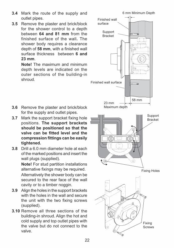
3.4 mark the route of the supply and outlet pipes.
3.5 remove the plaster and brick/block for the shower control to a depth between 64 and 81 mm from the finished surface of the wall. The shower body requires a clearance depth of 58 mm, with a finished wall surface thickness between 6 and 23 mm.
note! The maximum and minimum depth levels are indicated on the outer sections of the building-in shroud.
3.6 remove the plaster and brick/block for the supply and outlet pipes.
3.7 Mark the support bracket fixing hole positions. The support brackets should be positioned so that the valvecanbefitted level and thecompressionfittingscanbeeasilytightened.
3.8 Drill a 6.0 mm diameter hole at each of the marked positions and insert the wall plugs (supplied).
note! For stud partition installations alternative fixings may be required.
alternatively the shower body can be secured to the rear face of the wall cavity or to a timber noggin.
3.9 align the holes in the support brackets with the holes in the wall and secure the unit with the two fixing screws (supplied).
3.10 remove all three sections of the building-in shroud. align the hot and cold supply and top outlet pipes with the valve but do not connect to the valve.
Fixing Screws
SupportBracket
Fixing Holes
23
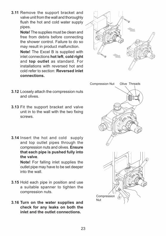
3.11 remove the support bracket and valve unit from the wall and thoroughly flush the hot and cold water supply pipes.
note! The supplies must be clean and free from debris before connecting the shower control. Failure to do so may result in product malfunction.
note! The Excel B is supplied with inlet connections hot left, cold right and top outlet as standard. For installations with reversed hot and cold refer to section: Reversed inlet connections.
3.12 loosely attach the compression nuts and olives.
3.13 Fit the support bracket and valve unit in to the wall with the two fixing screws.
3.14 Insert the hot and cold supply and top outlet pipes through the compression nuts and olives. ensure that each pipe is pushed fully into the valve.
note! For falling inlet supplies the outlet pipe may have to be set deeper into the wall.
3.15 Hold each pipe in position and use a suitable spanner to tighten the compression nuts.
3.16 Turn on the water supplies and check for any leaks on both the inlet and the outlet connections.
compression Nut Olive Threads
compression Nut
24
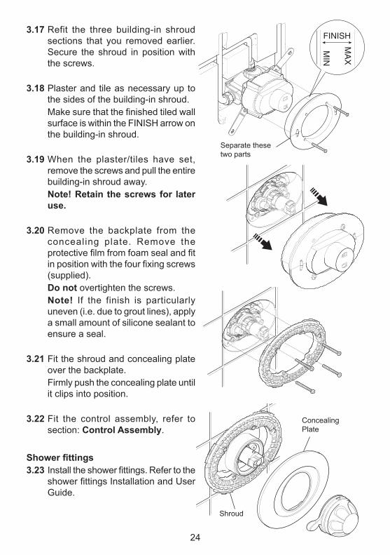
3.17 refit the three building-in shroud sections that you removed earlier. Secure the shroud in position with the screws.
3.18 Plaster and tile as necessary up to the sides of the building-in shroud.
Make sure that the finished tiled wall surface is within the FINISH arrow on the building-in shroud.
3.19 When the plaster/tiles have set, remove the screws and pull the entire building-in shroud away.
note! Retain the screws for later use.
3.20 remove the backplate from the concealing plate. remove the protective film from foam seal and fit in position with the four fixing screws (supplied).
Do not overtighten the screws. note! If the finish is particularly
uneven (i.e. due to grout lines), apply a small amount of silicone sealant to ensure a seal.
3.21 Fit the shroud and concealing plate over the backplate.
Firmly push the concealing plate until it clips into position.
3.22 Fit the control assembly, refer to section: Control Assembly.
Showerfittings3.23 Install the shower fittings. Refer to the
shower fittings Installation and User Guide.
Shroud
concealing Plate
Separate these two parts
25
6 mm minimum Depth4 - 18 mm
Finished wall surface
23 mm maximum depth
58 mm clearance
Finished wall surface
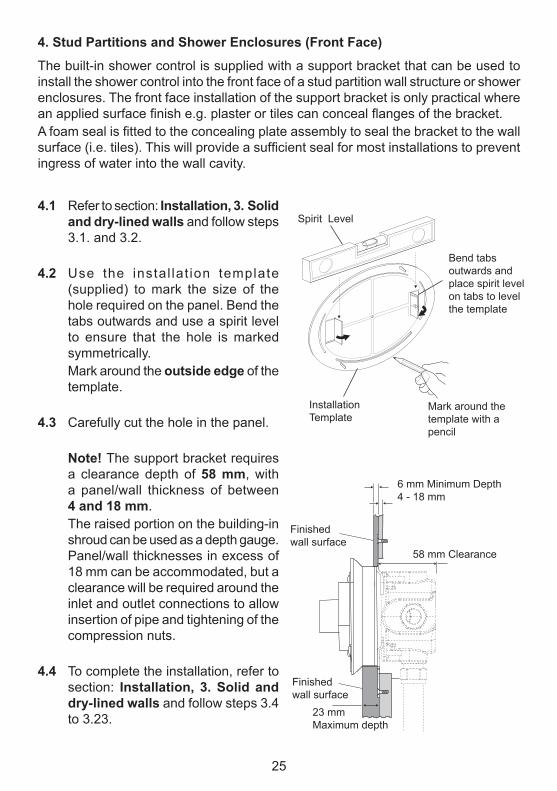
4. stud Partitions and shower enclosures (Front Face)
The built-in shower control is supplied with a support bracket that can be used to install the shower control into the front face of a stud partition wall structure or shower enclosures. The front face installation of the support bracket is only practical where an applied surface finish e.g. plaster or tiles can conceal flanges of the bracket.A foam seal is fitted to the concealing plate assembly to seal the bracket to the wall surface (i.e. tiles). This will provide a sufficient seal for most installations to prevent ingress of water into the wall cavity.
4.1 refer to section: Installation, 3. solid and dry-lined walls and follow steps 3.1. and 3.2.
4.2 Use the instal lat ion template (supplied) to mark the size of the hole required on the panel. Bend the tabs outwards and use a spirit level to ensure that the hole is marked symmetrically.
mark around the outside edge of the template.
4.3 carefully cut the hole in the panel.
note! The support bracket requires a clearance depth of 58 mm, with a panel/wall thickness of between 4 and 18 mm.
The raised portion on the building-in shroud can be used as a depth gauge. Panel/wall thicknesses in excess of 18 mm can be accommodated, but a clearance will be required around the inlet and outlet connections to allow insertion of pipe and tightening of the compression nuts.
4.4 To complete the installation, refer to section: Installation, 3. solid and dry-lined walls and follow steps 3.4 to 3.23.
Spirit level
InstallationTemplate
Bend tabs outwards and place spirit level on tabs to level the template
mark around the template with a pencil
26
Spirit level
InstallationTemplate
Bend tabs outwards and place spirit level on tabs to level the template
mark through the slot in the template with a pencil
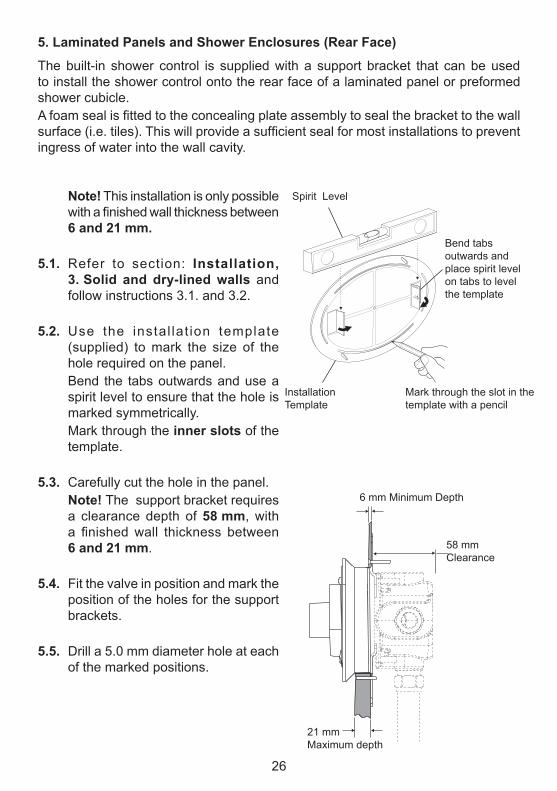
5. laminated Panels and shower enclosures (Rear Face)
The built-in shower control is supplied with a support bracket that can be used to install the shower control onto the rear face of a laminated panel or preformed shower cubicle.A foam seal is fitted to the concealing plate assembly to seal the bracket to the wall surface (i.e. tiles). This will provide a sufficient seal for most installations to prevent ingress of water into the wall cavity.
note! This installation is only possible with a finished wall thickness between 6 and 21 mm.
5.1. refer to section: Installation, 3. solid and dry-lined walls and follow instructions 3.1. and 3.2.
5.2. Use the instal lat ion template (supplied) to mark the size of the hole required on the panel.
Bend the tabs outwards and use a spirit level to ensure that the hole is marked symmetrically.
mark through the inner slots of the template.
5.3. carefully cut the hole in the panel. note! The support bracket requires
a clearance depth of 58 mm, with a finished wall thickness between 6 and 21 mm.
5.4. Fit the valve in position and mark the position of the holes for the support brackets.
5.5. Drill a 5.0 mm diameter hole at each of the marked positions.
6 mm minimum Depth
21 mm maximum depth
58 mm clearance
27
m4 x 30 mm Screws
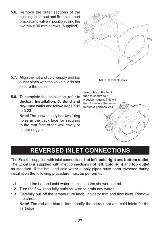
5.6. remove the outer sections of the building-in shroud and fix the support bracket and valve in position using the two m4 x 30 mm screws (supplied).
5.7. align the hot and cold supply and top outlet pipes with the valve but do not secure the pipes.
5.8. To complete the installation, refer to Section: Installation, 3. solid and dry-lined walls and follow steps 3.11 to 3.23.
note! The shower body has two fixing holes in the back face for securing to the rear face of the wall cavity or timber noggin.
Two holes in the backface to secure to a wooden noggin. This will help to secure the valve behind a partition wall.
ReveRseD InleT ConneCTIonsThe Excel is supplied with inlet connections hot left, cold right and bottom outlet. The Excel B is supplied with inlet connections hot left, cold right and top outlet as standard. If the hot and cold water supply pipes have been reversed during installation the following procedure must be performed.
1.1 Isolate the hot and cold water supplies to the shower control.1.2 Turn the flow knob fully anticlockwise to drain any water.1.3 Carefully pull off the temperature knob, indicator trim and flow lever. Remove
the shroud. note! The red and blue pillars identify the correct hot and cold inlets for the
cartridge.
28
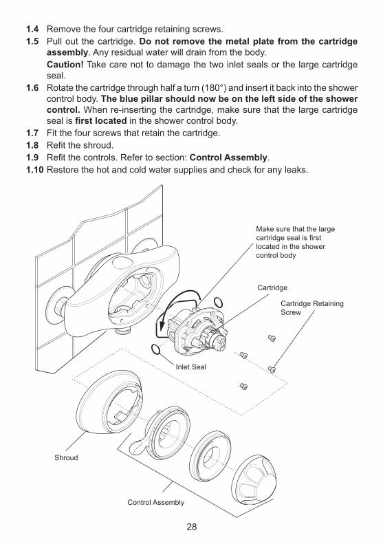
1.4 remove the four cartridge retaining screws.1.5 Pull out the cartridge. Do not remove the metal plate from the cartridge
assembly. any residual water will drain from the body. Caution! Take care not to damage the two inlet seals or the large cartridge
seal.1.6 rotate the cartridge through half a turn (180°) and insert it back into the shower
control body. The blue pillar should now be on the left side of the shower control. When re-inserting the cartridge, make sure that the large cartridge seal is firstlocated in the shower control body.
1.7 Fit the four screws that retain the cartridge.1.8 Refit the shroud.1.9 Refit the controls. Refer to section: Control Assembly.1.10 restore the hot and cold water supplies and check for any leaks.
Inlet Seal
Shroud
cartridge retaining Screw
control assembly
make sure that the large cartridge seal is first located in the shower control body
cartridge
29
ConTRol AsseMBlyThe procedure below details the steps required to fit the control assembly and is applicable to both the exposed and built-in models.
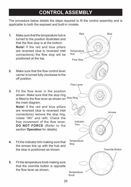
1. make sure that the temperature hub is turned to the position illustrated and that the flow stop is at the bottom.
note! If the red and blue pillars are reversed (due to reversed inlet connections) the flow stop will be positioned at the top.
2. Make sure that the flow control lever carrier is turned fully clockwise to the off position.
3. Fit the flow lever in the position shown. make sure that the stop ring is fitted to the flow lever as shown on the inset diagram.
note! If the red and blue pillars are reversed (due to reversed inlet connections) remove the stop ring, rotate 180° and refit. check the free movement of the flow lever, Do noT FoRCe (refer to the section operation for details)
4. Fit the indicator trim making sure that the arrows line up with the hub and the stop is positioned as shown.
5. Fit the temperature knob making sure that the override button is opposite the flow lever as shown.
Temperature Hub
Temperature Stop
arrows
Override Button
Temperature Knob
Indicator Trim
Flow lever
Stop ring
Flow Stop
red Blue
30
1. Maximum temperature setting
all mira Excel shower controls are fully performance tested and the maximum temperature has been set under ideal installation conditions at the factory. The temperature stop is set to 41°c and depressing the override will increase the temperature by 5°c to approximately 46°c. Site conditions and personal preference may make it necessary to reset these temperatures.note! an adequate supply of hot water at least 12°c above the required temperature must be available for correct operation of the shower control.
CoMMIssIonInG
Flow lever Temperature Knob
TemperatureHub
Temperature Hub Securing Screw
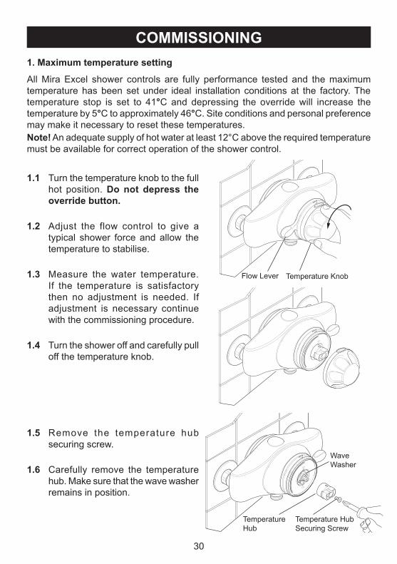
1.1 Turn the temperature knob to the full hot position. Do not depress the override button.
1.2 adjust the flow control to give a typical shower force and allow the temperature to stabilise.
1.3 measure the water temperature. If the temperature is satisfactory then no adjustment is needed. If adjustment is necessary continue with the commissioning procedure.
1.4 Turn the shower off and carefully pull off the temperature knob.
1.5 remove the temperature hub securing screw.
1.6 carefully remove the temperature hub. make sure that the wave washer remains in position.
Wave Washer
31
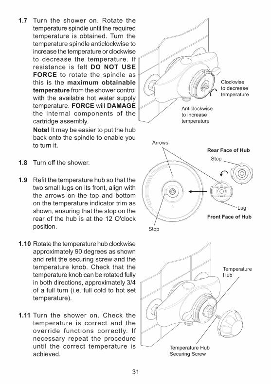
1.7 Turn the shower on. rotate the temperature spindle until the required temperature is obtained. Turn the temperature spindle anticlockwise to increase the temperature or clockwise to decrease the temperature. If resistance is felt Do noT use FoRCe to rotate the spindle as this is the maximum obtainable temperature from the shower control with the available hot water supply temperature. FoRCe will DAMAGe the internal components of the cartridge assembly.
note! It may be easier to put the hub back onto the spindle to enable you to turn it.
1.8 Turn off the shower.
1.9 Refit the temperature hub so that the two small lugs on its front, align with the arrows on the top and bottom on the temperature indicator trim as shown, ensuring that the stop on the rear of the hub is at the 12 O'clock position.
1.10 rotate the temperature hub clockwise approximately 90 degrees as shown and refit the securing screw and the temperature knob. check that the temperature knob can be rotated fully in both directions, approximately 3/4 of a full turn (i.e. full cold to hot set temperature).
1.11 Turn the shower on. check the temperature is correct and the override functions correctly. If necessary repeat the procedure until the correct temperature is achieved.
anticlockwise to increase temperature
clockwise to decrease temperature
Front Face of hub
Rear Face of hubarrows
Stop
Stop
lug
TemperatureHub
Temperature Hub Securing Screw
32
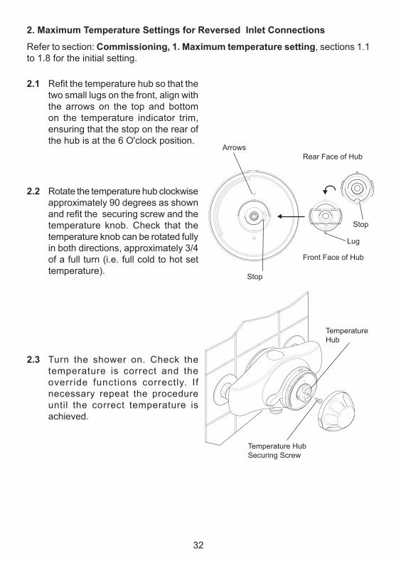
2. Maximum Temperature settings for Reversed Inlet Connections
refer to section: Commissioning, 1. Maximum temperature setting, sections 1.1 to 1.8 for the initial setting.
Front Face of Hub
rear Face of Hubarrows
Stop
Stop
lug
TemperatureHub
2.1 Refit the temperature hub so that the two small lugs on the front, align with the arrows on the top and bottom on the temperature indicator trim, ensuring that the stop on the rear of the hub is at the 6 O'clock position.
2.2 rotate the temperature hub clockwise approximately 90 degrees as shown and refit the securing screw and the temperature knob. check that the temperature knob can be rotated fully in both directions, approximately 3/4 of a full turn (i.e. full cold to hot set temperature).
2.3 Turn the shower on. check the temperature is correct and the override functions correctly. If necessary repeat the procedure until the correct temperature is achieved.
Temperature Hub Securing Screw
33
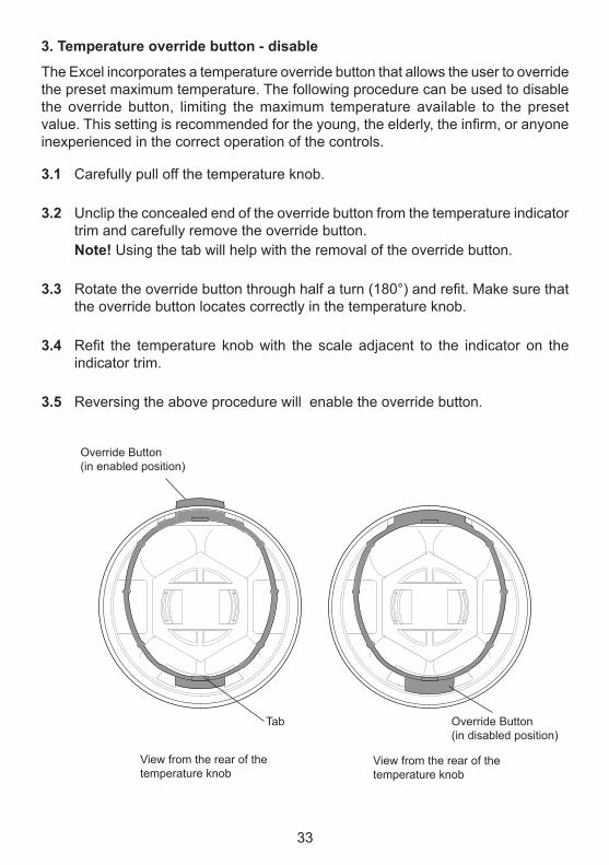
3.1 carefully pull off the temperature knob.
3.2 Unclip the concealed end of the override button from the temperature indicator trim and carefully remove the override button.
note! Using the tab will help with the removal of the override button.
3.3 Rotate the override button through half a turn (180°) and refit. Make sure that the override button locates correctly in the temperature knob.
3.4 Refit the temperature knob with the scale adjacent to the indicator on the indicator trim.
3.5 reversing the above procedure will enable the override button.
3. Temperature override button - disable
The Excel incorporates a temperature override button that allows the user to override the preset maximum temperature. The following procedure can be used to disable the override button, limiting the maximum temperature available to the preset value. This setting is recommended for the young, the elderly, the infirm, or anyone inexperienced in the correct operation of the controls.
Override Button(in enabled position)
Override Button(in disabled position)
View from the rear of the temperature knob
View from the rear of the temperature knob
Tab
34
=
=
=
=
The Excel incorporates a temperature override button that allows the user to override the preset maximum temperature. It is recommended that this facility is disabled for the young, the elderly and the infirm, or anyone inexperienced in the correct operation of the controls. refer to Section: Commissioning, 3. Temperature override button - disable.
oPeRATIon
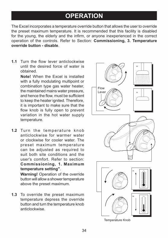
1.1 Turn the flow lever anticlockwise until the desired force of water is obtained.
note! When the Excel is installed with a fully modulating multipoint or combination type gas water heater, the maintained mains water pressure, and hence the flow, must be sufficient to keep the heater ignited. Therefore, it is important to make sure that the flow knob is fully open to prevent variation in the hot water supply temperature.
1.2 Tu rn t he t empera tu re knob anticlockwise for warmer water or clockwise for cooler water. The preset maximum temperature can be adjusted as required to suit both site conditions and the user's comfort. refer to section: Commissioning, 1. Maximum temperature setting".
Warning! Operation of the override button will allow a shower temperature above the preset maximum.
1.3 To override the preset maximum temperature depress the override button and turn the temperature knob anticlockwise.
Flow lever
Temperature Knob
35
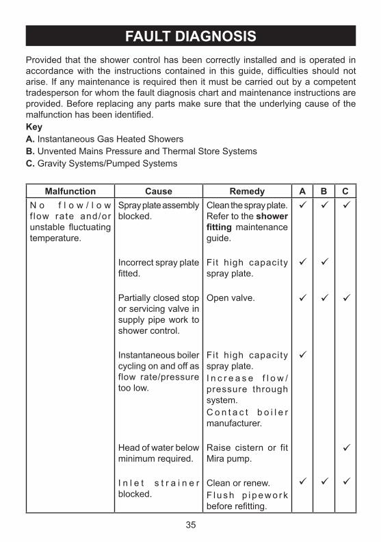
FAulT DIAGnosIsProvided that the shower control has been correctly installed and is operated in accordance with the instructions contained in this guide, difficulties should not arise. If any maintenance is required then it must be carried out by a competent tradesperson for whom the fault diagnosis chart and maintenance instructions are provided. Before replacing any parts make sure that the underlying cause of the malfunction has been identified.keyA. Instantaneous Gas Heated ShowersB. Unvented mains Pressure and Thermal Store SystemsC. Gravity Systems/Pumped Systems
Malfunction Cause Remedy A B CN o f l o w / l o w f low rate and/or unstable fluctuating temperature.
Spray plate assembly blocked.
Incorrect spray plate fitted.
Partially closed stop or servicing valve in supply pipe work to shower control.
Instantaneous boiler cycling on and off as flow rate/pressure too low.
Head of water below minimum required.
I n l e t s t r a i n e r blocked.
clean the spray plate. refer to the shower fitting maintenance guide.
Fit high capacity spray plate.
Open valve.
Fit high capacity spray plate.I n c r e a s e f l o w /pressure through system.c o n t a c t b o i l e r manufacturer.
raise cistern or fit mira pump.
clean or renew.F l u s h p i p e w o r k before refitting.
36
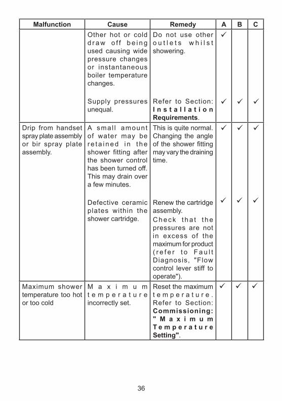
Malfunction Cause Remedy A B COther hot or cold d r a w o f f b e i n g used causing wide pressure changes or instantaneous boiler temperature changes.
Supply pressures unequal.
Do not use other o u t l e t s w h i l s t showering.
refer to Section: I n s t a l l a t i o n Requirements.
Drip from handset spray plate assembly or bir spray plate assembly.
a smal l amount of water may be r e t a i n e d i n t h e shower fitting after the shower control has been turned off. This may drain over a few minutes.
Defective ceramic plates within the shower cartridge.
This is quite normal. changing the angle of the shower fitting may vary the draining time.
renew the cartridge assembly.c h e c k t h a t t h e pressures are not in excess of the maximum for product ( r e f e r t o F a u l t Diagnosis, "Flow control lever stiff to operate").
maximum shower temperature too hot or too cold
m a x i m u m t e m p e r a t u r e incorrectly set.
reset the maximum t e m p e r a t u r e . refer to Section: Commissioning: " M a x i m u m T e m p e r a t u r e setting".

37
Malfunction Cause Remedy A B CShower temperature too cold (maximum temperature correctly set).
H o t w a t e r temperature less than 12°c above the required shower blend temperature.
Instantaneous boiler not igniting because the water flow rate is too low.
Instantaneous boiler not igniting because the water pressure is too low.
adjust the hot water t e m p e r a t u r e o r wait for the water to reheat if stored system.
Fit high capacity spray plate.Increase flow rate through the system.check the cartridge inlet filters, clean or replace.c o n t a c t b o i l e r manufacturer.
I n c r e a s e w a t e r pressure.c o n t a c t b o i l e r manufacturer.
leak from shower control body.
cartridge inlet or outlet seals missing or damaged.
Pressure build up causing damage to the cartr idge. This may be due to domestic hot water expansion.
Fit new seals.
Fi t domest ic hot water expansion vessel. If one already f i t ted, i t may be deflated and require repressurization.If necessary, fit new cartridge.
Flow control lever stiff to operate.
Pressure build up. This may be due to domestic hot water expansion.
Fi t domest ic hot water expansion vessel. If one already f i t ted, i t may be deflated and require repressurization.
38
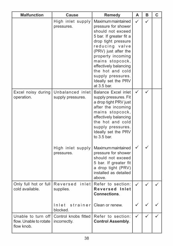
Malfunction Cause Remedy A B CHigh inlet supply pressures.
maximum maintained pressure for shower should not exceed 5 bar. If greater fit a drop tight pressure r e d u c i n g v a l v e (PrV) just after the property incoming mains s topcock, effectively balancing the hot and cold supply pressures. Ideally set the PrV at 3.5 bar.
Excel noisy during operation.
Unbalanced inlet supply pressures.
High inlet supply pressures.
Balance Excel inlet supply pressures. Fit a drop tight PrV just after the incoming mains s topcock, effectively balancing the hot and cold supply pressures. Ideally set the PrV to 3.5 bar.
maximum maintained pressure for shower should not exceed 5 bar. If greater fit a drop tight (PrV) installed as detailed above.
Only full hot or full cold available.
r e v e r s e d i n l e t supplies.
I n l e t s t r a i n e r blocked.
refer to section: R e v e r s e d I n l e t Connections.
clean or renew.
Unable to turn off flow. Unable to rotate flow knob.
Control knobs fitted incorrectly.
refer to section: Control Assembly.
39
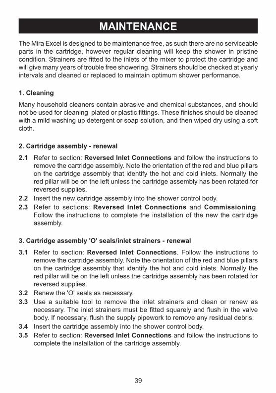
MAInTenAnCeThe mira Excel is designed to be maintenance free, as such there are no serviceable parts in the cartridge, however regular cleaning will keep the shower in pristine condition. Strainers are fitted to the inlets of the mixer to protect the cartridge and will give many years of trouble free showering. Strainers should be checked at yearly intervals and cleaned or replaced to maintain optimum shower performance.
1. Cleaning
many household cleaners contain abrasive and chemical substances, and should not be used for cleaning plated or plastic fittings. These finishes should be cleaned with a mild washing up detergent or soap solution, and then wiped dry using a soft cloth.
2. Cartridge assembly - renewal
2.1 refer to section: Reversed Inlet Connections and follow the instructions to remove the cartridge assembly. Note the orientation of the red and blue pillars on the cartridge assembly that identify the hot and cold inlets. Normally the red pillar will be on the left unless the cartridge assembly has been rotated for reversed supplies.
2.2 Insert the new cartridge assembly into the shower control body.2.3 refer to sections: Reversed Inlet Connections and Commissioning.
Follow the instructions to complete the installation of the new the cartridge assembly.
3. Cartridge assembly 'o' seals/inlet strainers - renewal
3.1 refer to section: Reversed Inlet Connections. Follow the instructions to remove the cartridge assembly. Note the orientation of the red and blue pillars on the cartridge assembly that identify the hot and cold inlets. Normally the red pillar will be on the left unless the cartridge assembly has been rotated for reversed supplies.
3.2 renew the 'O' seals as necessary.3.3 Use a suitable tool to remove the inlet strainers and clean or renew as
necessary. The inlet strainers must be fitted squarely and flush in the valve body. If necessary, flush the supply pipework to remove any residual debris.
3.4 Insert the cartridge assembly into the shower control body.3.5 refer to section: Reversed Inlet Connections and follow the instructions to
complete the installation of the cartridge assembly.
40
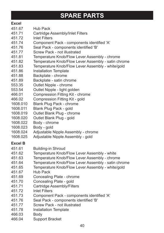
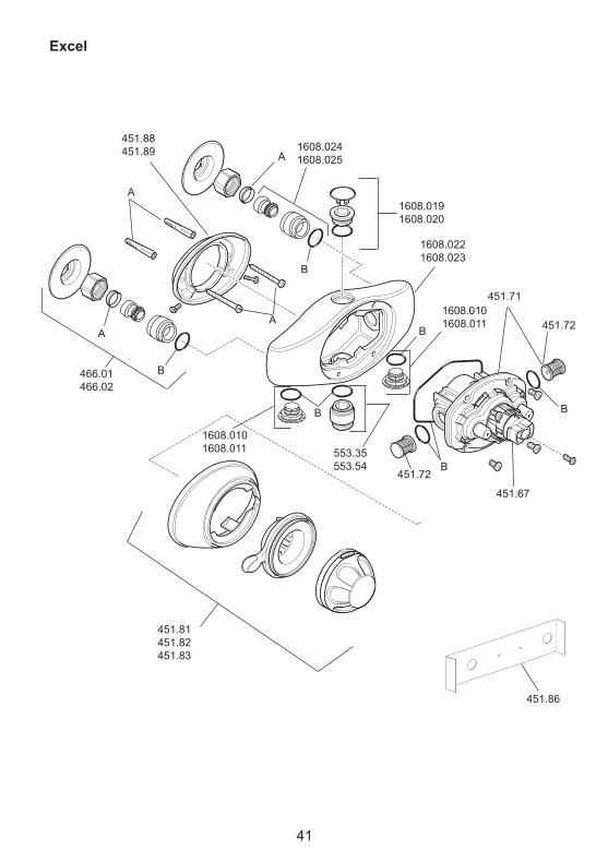
excel451.67 Hub Pack451.71 cartridge assembly/Inlet Filters451.72 Inlet Filters451.74 Component Pack - components identified 'A'451.76 Seal Pack - components identified 'B'451.77 Screw Pack - not illustrated451.81 Temperature Knob/Flow lever assembly - chrome451.82 Temperature Knob/Flow lever assembly - satin chrome451.83 Temperature Knob/Flow lever assembly - white/gold451.86 Installation Template451.88 Backplate - chrome451.89 Backplate - satin chrome553.35 Outlet Nipple - chrome553.54 Outlet Nipple - light golden466.01 compression Fitting Kit - chrome466.02 compression Fitting Kit - gold1608.010 Blank Plug Pack - chrome1608.011 Blank Plug Pack - gold1608.019 Outlet Blank Plug - chrome1608.020 Outlet Blank Plug - gold1608.022 Body - chrome1608.023 Body - gold1608.024 adjustable Nipple assembly - chrome1608.025 adjustable Nipple assembly - gold
sPARe PARTs
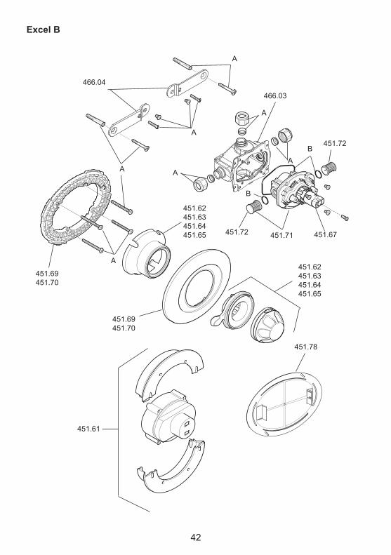
excel B451.61 Building-in Shroud451.62 Temperature Knob/Flow lever assembly - white451.63 Temperature Knob/Flow lever assembly - chrome451.64 Temperature Knob/Flow lever assembly - satin chrome451.65 Temperature Knob/Flow lever assembly - white/gold451.67 Hub Pack451.69 concealing Plate - chrome451.70 concealing Plate - gold451.71 cartridge assembly/Filters451.72 Inlet Filters451.73 Component Pack - components identified 'A'451.76 Seal Pack - components identified 'B'451.77 Screw Pack - not illustrated451.78 Installation Template466.03 Body466.04 Support Bracket
41
451.88451.89
451.71
451.72
451.67
1608.0191608.020
451.86
a
a
aa
1608.0101608.011
451.72
1608.0101608.011
451.81451.82451.83
B
553.35553.54 B
B
B
B
B466.01466.02
1608.0221608.023
1608.0241608.025
excel
42
466.04
451.61
466.03
451.67
451.69451.70
451.71
451.72
a
451.78
a
a
451.62451.63451.64451.65
a
a
a
B
B
451.72
a
451.62451.63451.64451.65
451.69451.70
excel B
43
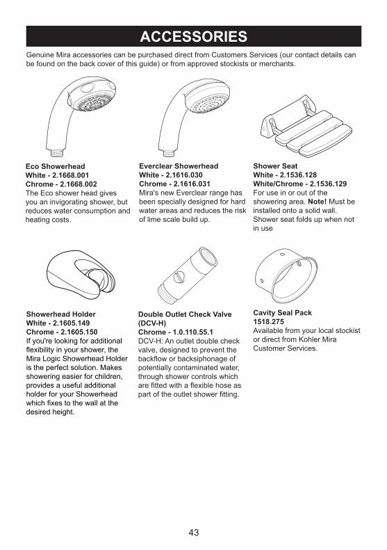
ACCessoRIes
eco showerheadWhite - 2.1668.001Chrome - 2.1668.002The Eco shower head gives you an invigorating shower, but reduces water consumption and heating costs.
everclear showerheadWhite - 2.1616.030Chrome - 2.1616.031mira's new Everclear range has been specially designed for hard water areas and reduces the risk of lime scale build up.
shower seatWhite - 2.1536.128White/Chrome - 2.1536.129For use in or out of the showering area. note! must be installed onto a solid wall.Shower seat folds up when not in use
Double outlet Check valve (DCv-h)Chrome - 1.0.110.55.1DcV-H: an outlet double check valve, designed to prevent the backflow or backsiphonage of potentially contaminated water, through shower controls which are fitted with a flexible hose as part of the outlet shower fitting.
Genuine mira accessories can be purchased direct from customers Services (our contact details can be found on the back cover of this guide) or from approved stockists or merchants.
showerhead holderWhite - 2.1605.149Chrome - 2.1605.150If you're looking for additional flexibility in your shower, the mira logic Showerhead Holder is the perfect solution. makes showering easier for children, provides a useful additional holder for your Showerhead which fixes to the wall at the desired height.
Cavity seal Pack1518.275available from your local stockist or direct from Kohler mira customer Services.
441068628-W2-D (1518) © Kohler mira limited, October 2009
CusToMeR seRvICeGuaranteeYour product has the benefit of our manufacturer’s guarantee which starts from the date of purchase.To activate this guarantee, please return your completed registration card, visit our website or free phone 0800 0731248 within 30 days of purchase (UK only).Within the guarantee period we will resolve defects in materials or workmanship, free of charge, by repairing or replacing parts or product as we may choose.This guarantee is in addition to your statutory rights and is subject to the following conditions: ● The product must be installed and maintained in accordance with the instructions given in this user guide. ● Servicing must only be undertaken by us or our appointed representative. Note! if a service visit is required the product must be fully installed and connected to services. ● Repair under this guarantee does not extend the original expiry date. The guarantee on any replacement parts or product ends at the original expiry date. ● For shower fi ttings or consumable items we reserve the right to supply replacement parts only.The guarantee does not cover: ● Call out charges for non product faults (such as
damage or performance issues arising from incorrect installation, improper use, lack of maintenance, build up of limescale, frost damage, corrosion, system debris or blocked fi lters) or where no fault has been found with the product.
● Water or electrical supply, waste and isolation issues. ● Compensation for loss of use of the product or
consequential loss of any kind. ● Damage or defects caused if the product is repaired
or modifi ed by persons not authorised by us or our appointed representative.
● Routine maintenance or replacement parts to comply with the requirements of the TMV 2 or TMV 3 healthcare schemes.
What to do if something goes wrongIf your product does not function correctly when you fi rst use it, contact your installer to check that it is installed and commissioned in accordance with the instructions in this manual.Should this not resolve the issue, contact our Customer Services Team who will offer you or your installer advice and if applicable arrange for a Service Technician to call.If the performance of your product declines, check in this manual to see if simple home maintenance is required. If you require further assistance call our Customer Services Team.Extended GuaranteesA selection of protection plans are available that enable you to cover repair bills for the life of your policy (excludes Eire). Ring 01922 471763 for more details.
Helpdesk ServiceOur dedicated Customer Services Team is comprehensively trained and can offer help and advice, spare parts, accessories or a service visit. We will need you to have your model name or number, power rating (if applicable) and date of purchase. As part of our quality and training programme calls may be recorded or monitored.Mira Showers Website (www.mirashowers.co.uk)From our website you can register your guarantee, download additional user guides, diagnose faults, purchase our full range of accessories and popular spares, refer to our FAQ’s and request a service visit.Spares and AccessoriesWe maintain extensive stocks of genuine spares and accessories and aim to provide support throughout the product’s expected life. Payment can be made by phone at time of order using most major Credit or Debit cards and we aim to despatch orders within two working days. Items purchased from us are guaranteed for 12 months from date of purchase. For safety reasons spares exposed to mains voltages should only be fi tted by competent persons.Returns – items can be returned within one month of date of purchase, providing that they are in good condition and the packaging is unopened. Please obtain authorisation from our Customer Services Team before return. We reserve the right to apply a 15% restocking charge.Service / RepairsWe have a nationwide team of Service Technicians who can carry out all service or repair work to your product within the guarantee period and beyond. You have the assurance of a fully trained Mira Technician, genuine Mira spare parts and a 12 month guarantee on any chargeable work done.Payment should be made directly to the Service Technician who will accept most major Credit or Debit cards.
To Contact UsUKTelephone: 0844 571 5000Mon to Fri 8:00 am - 5:30 pm, Sat 8:30 am - 3:30 pmE-mail: [email protected]: 01242 282595By Post: Mira Customer Services Dept, Cromwell Road, Cheltenham, Gloucestershire, GL52 5EP
EireTelephone: 01 459 1344Mon to Fri 9:00 am - 5:00 pmE-mail: [email protected]: Dublin 01 459 2329By Post: Modern Plant Ltd (Dublin),Otter House, Naas Road, Clondalkin, Dublin 22
Mira is a registered trade mark of Kohler Mira Limited.
The company reserves the right to alter product specifi cations without notice.


