32
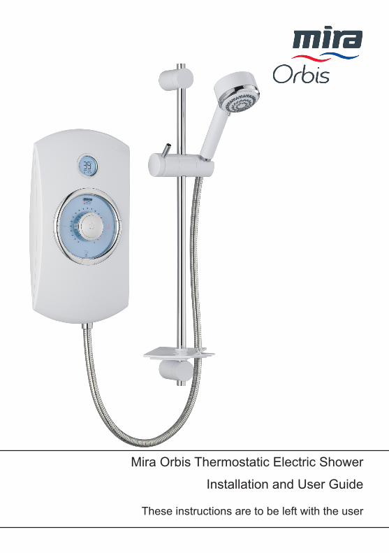
These instructions are to be left with the user Installation and User Guide Mira Orbis Thermostatic Electric Shower
�
These instructions are to be left with the user
Installation and User Guide
Mira Orbis Thermostatic Electric Shower

�
ContentsPatents and Design Registration ..........................................................�
Introduction..............................................................................................3Important.Safety.Information..................................................................4
Warning! ...............................................................................................4Caution! ................................................................................................5
Pack.Contents.Checklist.........................................................................6Specifications...........................................................................................7Installation.Requirements.......................................................................7Installation..............................................................................................10
Installation of Mira Orbis .....................................................................�0Commissioning......................................................................................14User.Instructions....................................................................................16
Clock Setting ......................................................................................�0Fault.Diagnosis.......................................................................................22
Heater Settings ...................................................................................��Maintenance............................................................................................26
Handset - Cleaning .............................................................................�6Inlet Filter - Cleaning/Renewing .........................................................�6Clock Battery Replacement Procedure ..............................................�7
Spare.Parts.............................................................................................28Mira Orbis ...........................................................................................�8
Accessories............................................................................................28Dimensions.............................................................................................30Wiring.Diagram.......................................................................................30Customer.Services.................................................................................31
Patents.and.Design.Registration
Design.Registration 000738�4�-000�Patents GB: � 34� 667
Eire: 8�835Patent.Applications UK: � 4�8 �86, � 4�7 460
Eire: �004/0483, �006/046�

3
IntroductionThank you for purchasing a quality Mira product. To enjoy the full potential of your new product, please take time to read this guide thoroughly. Having done so, keep it handy for future reference.
The Mira Orbis is a thermostatic electric shower with separate controls for power selection and temperature/flow adjustment. A unique thermostatic valve stabilises temperature changes caused by water pressure fluctuations. These can result from taps being turned on or off, or toilets being flushed. A digital display indicates shower temperature, clock (with battery backup), low flow and over temperature warnings.The Mira Orbis comes complete with a set of Mira Energise Shower Fittings.
Mira.Orbis.9.0.kWA 9.0 kW 240 V AC (8.2 kW 230 V AC) heater with Mira Energise adjustable spray handset with four different spray actions (start, soothe, force and eco*). Supplied complete with flexible hose, clamp bracket assembly, slide bar, supports, hose retaining ring and soap dish. Available in white/chrome.
Mira.Orbis.9.8.kWA 9.8 kW 240 V AC (9.0 kW 230 V AC) heater with Mira Energise adjustable spray handset with four different spray actions (start, soothe, force and eco*). Supplied complete with flexible hose, clamp bracket assembly, slide bar, supports, hose retaining ring and soap dish. Available in white/chrome and black/chrome finish.
Mira.Orbis.10.8.kWA 10.8 kW 240 V AC (9.9 kW 230 V AC) heater with Mira Energise adjustable spray handset with four different spray actions (start, soothe, force and eco*). Supplied complete with flexible hose, clamp bracket assembly, slide bar, supports, hose retaining ring and soap dish. Available in white/chrome finish.
* The eco setting reduces the water flow to give economical use of water, whilst still giving an adequate shower performance. This setting performs best with most gravity, pumped, and mains pressure unvented systems. On electric showers and some combination boiler systems the economy setting will have no effect, and will give the same spray action as the start setting.
If you experience any difficulty with the installation or operation of your new Electric Shower, please refer to ‘Fault Diagnosis’, before contacting Kohler Mira Ltd. Our telephone and fax numbers can be found on the back cover of this guide.

4
Important.Safety.InformationInstallation must be carried out in accordance with these instructions, and must be conducted by designated, qualified and competent personnel.Warning!Follow.all.warnings,.cautions.and.instructions.contained.in.this.guide,.and.on.or.inside.the.appliance.
1. Products manufactured by us are safe and risk-free, provided that they are installed, used and maintained in good working order, in accordance with our instructions and recommendations.
2. Isolate the electrical and water supplies before commencing installation. The electricity must be turned off at the mains and the appropriate circuit fuse removed, if applicable.
3. Mains connections are exposed when the cover is removed.4. Refer to the wiring diagram before making any electrical connections (refer to
the wiring diagram at the back of this guide).5. Make sure that any pipework that could become frozen is properly insulated.6. Having completed the installation, make sure that the user is familiar with the
operation of the appliance.7. Make sure that this guide is left with the user.8. DO.NOT commission this appliance if water leaks from the unit or the heater
tank pressure relief valve.9. DO.NOT fit any form of outlet control (e.g. Trigger handset) as the outlet acts
as a vent for the tank body. Only Mira recommended outlet fittings should be used.
10. Make sure all electrical connections are tight, to prevent overheating.11. The shower unit must not be fitted where it may be exposed to freezing
conditions. Make sure that any pipework that could become frozen is properly insulated. If the appliance appears to be frozen, allow to thaw and then contact your installer before using again.
12. This product is not suitable for areas with high humidity (i.e steam rooms). Please consult your installer.
13. THIS.APPLIANCE.MUST.BE.EARTHED..MAKE.SURE.SUPPLEMENTARY.BONDING. COMPLIES. WITH. THE. “REQUIREMENTS. FOR. ELECTRICAL.INSTALLATIONS”.
The installation must be in accordance with the current edition of ’The Plugs and Sockets etc. (Safety) Regulations’ in force at the time of installation, this Mira Orbis is intended to be permanently connected to the fixed electrical wiring of the mains system.

5
Caution!1. Read all of these instructions and retain this guide for later use.2. The electrical installation must comply to “BS 767� - Requirements for Electrical
Installations”, commonly referred to as the IEE Wiring Regulations - Part 7, or any particular regulations and practices, specified by the local electricity supply company.
3. The plumbing installation must comply with the requirements of UK Water Regulations/Bye-laws (Scotland), Building Regulations or any particular regulations and practices, specified by the local water company or water undertakers.
4. Make sure that you fully understand how to operate this shower and make sure that it is properly maintained in accordance with the instructions given in this manual.
5. Anyone who may have difficulty understanding or operating the controls of any shower should be attended whilst showering. Particular consideration should be given to:
5.1. The young.5.2. The elderly.5.3. The infirm.5.4. The disabled.5.5. Anyone who suffers from a medical condition that can result in temporary
incapacity (e.g. epilepsy or blackouts).5.6. Anyone inexperienced in the correct operation of the controls.
6. Sunburn or skin conditions can increase your sensitivity to hot water. Make sure that you set the shower to a cooler temperature.
7. If any of the following conditions occur, isolate the electricity and water supplies and refer to “To contact us”, on the back page of this guide:
7.1. If the cover is not correctly fitted and water has entered the appliance case.
7.2. If the case is damaged.7.3. If the appliance begins to make an odd noise, smell or smoke.7.4. If the appliance shows signs of a distinct change in performance,
indicating a need for maintenance.7.5. DO.NOT operate this appliance if water leaks from this appliance.
8. When this appliance has reached the end of its serviceable life, it should be disposed of in a safe manner, in accordance with current local authority recycling, or waste disposal policy.

6
Pack.Contents.Checklist
Mira.Orbis
3 x Wall Plugs
3 x Fixing Screws
1 x Mira Orbis
1 x Compression Nut
1 x Olive
2 x Case Inserts
Tick the appropriate boxes to familiarise yourself with the part names and to confirm that the parts are included.
Documentation
1 x Guarantee Registration Document
1 x Installation Template
1 x Installer Checklist
7
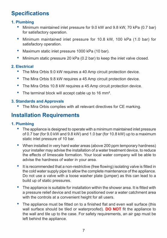
Specifications1..Plumbing
Minimum maintained inlet pressure for 9.0 kW and 9.8 kW, 70 kPa (0.7 bar) for satisfactory operation.
Minimum maintained inlet pressure for �0.8 kW, �00 kPa (�.0 bar) for satisfactory operation.
Maximum static inlet pressure 1000 kPa (10 bar).
Minimum static pressure �0 kPa (0.� bar) to keep the inlet valve closed.
2..ElectricalThe Mira Orbis 9.0 kW requires a 40 Amp circuit protection device.
The Mira Orbis 9.8 kW requires a 45 Amp circuit protection device.
The Mira Orbis 10.8 kW requires a 45 Amp circuit protection device.
The terminal block will accept cable up to �6 mm².
3..Standards.and.ApprovalsThe Mira Orbis complies with all relevant directives for CE marking.
Installation.Requirements1..Plumbing
The appliance is designed to operate with a minimum maintained inlet pressure of 0.7 bar (for 9.0 kW and 9.8 kW) and 1.0 bar (for 10.8 kW) up to a maximum static inlet pressure of �0 bar.
When installed in very hard water areas (above �00 ppm temporary hardness) your installer may advise the installation of a water treatment device, to reduce the effects of limescale formation. Your local water company will be able to advise the hardness of water in your area.
It is recommended that a non-restrictive (free flowing) isolating valve is fitted in the cold water supply pipe to allow the complete maintenance of the appliance. Do not use a valve with a loose washer plate (jumper) as this can lead to a build up of static pressures.
The appliance is suitable for installation within the shower area. It is fitted with a pressure relief device and must be positioned over a water catchment area with the controls at a convenient height for all users.
The appliance must be fitted on to a finished flat and even wall surface (this wall surface should be tiled or waterproofed). DO.NOT fit the appliance to the wall and tile up to the case. For safety requirements, an air gap must be left behind the appliance.
•
•
••
••••
•
•
•
•
•
•
8
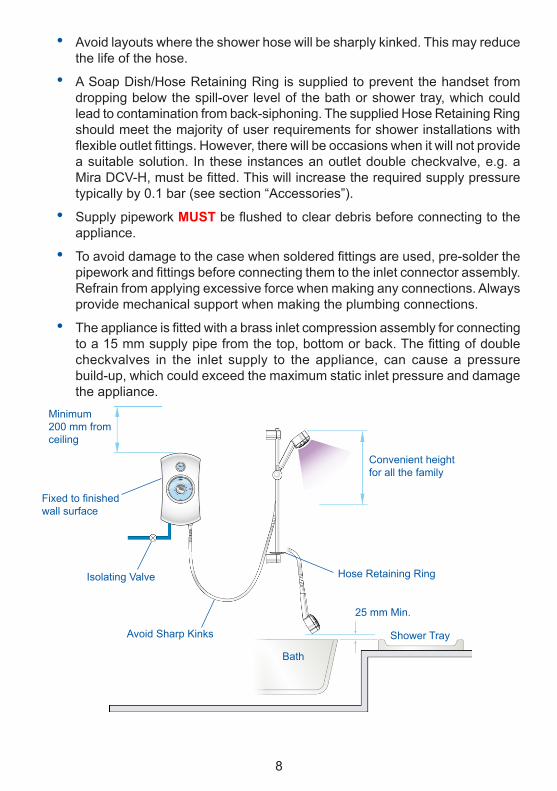
Avoid layouts where the shower hose will be sharply kinked. This may reduce the life of the hose.
A Soap Dish/Hose Retaining Ring is supplied to prevent the handset from dropping below the spill-over level of the bath or shower tray, which could lead to contamination from back-siphoning. The supplied Hose Retaining Ring should meet the majority of user requirements for shower installations with flexible outlet fittings. However, there will be occasions when it will not provide a suitable solution. In these instances an outlet double checkvalve, e.g. a Mira DCV-H, must be fitted. This will increase the required supply pressure typically by 0.1 bar (see section “Accessories”).
Supply pipework MUST be flushed to clear debris before connecting to the appliance.
To avoid damage to the case when soldered fittings are used, pre-solder the pipework and fittings before connecting them to the inlet connector assembly. Refrain from applying excessive force when making any connections. Always provide mechanical support when making the plumbing connections.
The appliance is fitted with a brass inlet compression assembly for connecting to a 15 mm supply pipe from the top, bottom or back. The fitting of double checkvalves in the inlet supply to the appliance, can cause a pressure build-up, which could exceed the maximum static inlet pressure and damage the appliance.
•
•
•
•
•
Isolating Valve
Avoid Sharp Kinks
Convenient height for all the family
�5 mm Min.
Bath
Shower Tray
Fixed to finished wall surface
Minimum �00 mm from ceiling
Hose Retaining Ring

9
2..ElectricalIn a domestic installation, the rating of the electricity supplier’s fuse and the consumer unit must be adequate for the additional demand. All Mira electric showers are high power units, it is essential to contact your electricity supplier to ensure that the supply is adequate for the product. Voltage drop due to local heavy demand will reduce the shower’s performance.
The appliance must. be. earthed by connecting the supply-cable earth conductor to the earth terminal. Supplementary bonding: Within the bathroom or shower room, all accessible conductive parts of electrical equipment and extraneous conductive parts (metal parts) that are likely to introduce earth potential, must be electrically bonded to earth using a minimum cable size of 4.0 mm� if the cable is not mechanically protected, (�.5 mm� if mechanically protected).
The minimum cable size (cross-sectional area) required should be in accordance with BS 767�.
As a guide only, and in accordance with BS 7671 we recommend close circuit protection: i.e. 9.8 kW = 45 Amp
It is strongly recommended that a 30mA Residual Current Device (RCD) is included in the electrical circuit. This may be part of the consumer unit or a separate unit.
A separate, permanently connected supply must be taken from the consumer unit to the appliance through a double-pole switch, which has at least 3 mm contact separation. The switch can be a ceiling mounted pullcord type within the shower room or a wall mounted switch in an adjacent room.
DO.NOT twist the individual cable cores of either the live or neutral conductors, as this will prevent them from entering the terminal block.
DO. NOT exert strain on the terminal block. Make sure that the electrical connections are tightly screwed down.
DO. NOT turn-on the electrical supply until the plumbing has been completed.
•
•
•
•
•
•
•
•
•

�0
Double-poleIsolating Switch
Consumer Unit
InstallationInstallation.of.Mira.Orbis
Warning! Turn off the electrical and water supplies before proceeding with the installation of the Mira Orbis. The electricity must be turned off at the mains and the appropriate circuit fuse removed, if applicable.
Note! An installation template is supplied to help you install the Mira Orbis.
Remove the three cover retaining screws.
Carefully remove the cover, making sure that you do not strain the multi-connector.
Carefully remove the multi-connector from the socket on the control PCB in the case
Remove the service tunnel.Cover
Cover Retaining Screw
Service Tunnel

��
Two case inserts are supplied with the Mira Orbis, so that they can be trimmed to suit the supplies entering the product. Before fitting the cover, make sure that the case inserts are fitted.
Thoroughly flush the mains-fed cold water supply pipe. The supply must be.clean.and.free.from.debris..BEFORE.connecting.the.Mira.Orbis.To flush the pipework, turn on the water supply and drain a minimum of 10 litres (� gallons) of water into a bucket or catchment area. Turn off the water supply.
An installation template is supplied to help you install the Mira Orbis.Put the installation template on the wall and mark through the positions of the fixing holes. Make sure that the position of these holes do not come in line with any buried cables or pipework. Make sure that sufficient electrical supply cable is available for connection to the terminal block.
Drill and plug the top two fixing holes. Secure the Mira Orbis to the wall with the screws provided. Drill the bottom fixing hole with the product in place. Alternative fixings (not supplied) may be necessary for some wall structures. Avoid drilling into any supply cable/pipe.
Determine the direction of the inlet water supply: top (falling), bottom (rising), or back inlet.
Note! Make sure that the back inlet does not go directly back into the wall. Use a soldered elbow.
Swivel the inlet connector assembly to suit. Remove the inlet blanking cap. Avoid trapping the green earth bonding wire.
Install the mains-fed cold water supply pipe. Do not overtighten.

��
Feed cable into Case. Fit Earth sleeve (not supplied) and strip insulation.Do not twist cable cores.
Firmly connect the conductors. Do not exert strain on the terminal block.
L = BROWNE = GREEN/YELLOW
N = BLUE
Before refitting the cover, pull the plastic tab off the battery to activate it.
Refit the Service Tunnel.
Connect the multi-connector to the socket on the PCB.
Refit the Cover. Make sure that it fits correctly. Do not overtighten screws.
Do not use alternative screws to secure the Cover. This can cause internal damage to the appliance. Do not seal around the back of appliance.
Install the shower fittings in accordance with the manufacturer’s instructions.
Cover
Cover Retaining Screw
Service Tunnel
Important! Make sure that the inlet earth wire is routed as shown. Failure to do so may cause product malfunction.
�3
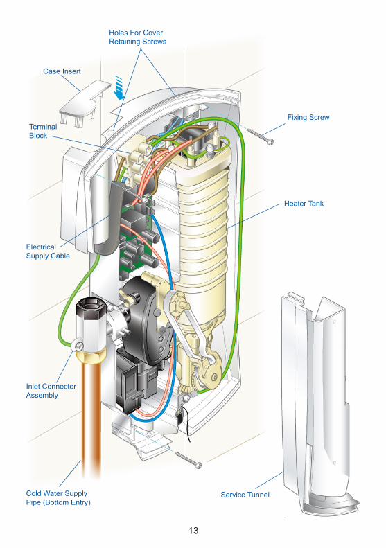
Cold Water Supply Pipe (Bottom Entry)
Service Tunnel
Fixing Screw
Holes For CoverRetaining Screws
Case Insert
Electrical Supply Cable
Terminal Block
Inlet Connector Assembly
Heater Tank
�4
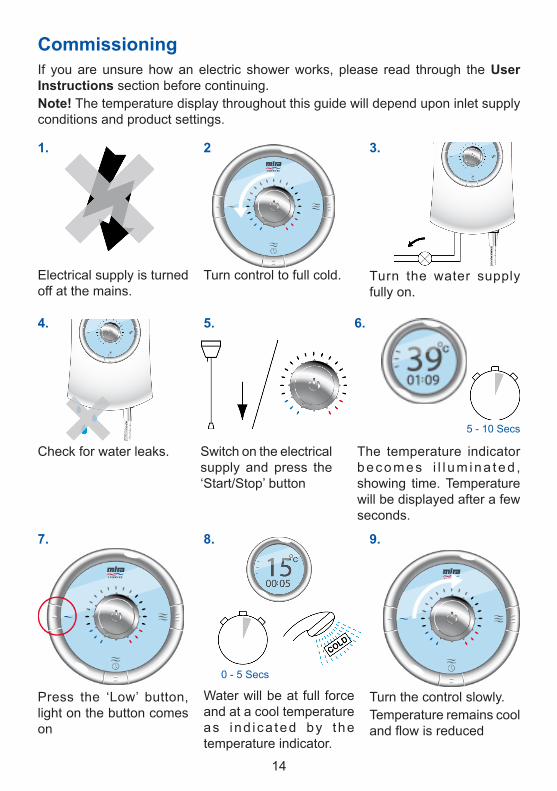
CommissioningIf you are unsure how an electric shower works, please read through the User.Instructions section before continuing.Note! The temperature display throughout this guide will depend upon inlet supply conditions and product settings.
Turn control to full cold. Turn the water supply fully on.
Check for water leaks. Switch on the electrical supply and press the ‘Start/Stop’ button
The temperature indicator becomes i l l um ina ted , showing time. Temperature will be displayed after a few seconds.
Press the ‘Low’ button, light on the button comes on
Water will be at full force and at a cool temperature as ind ica ted by the temperature indicator.
Turn the control slowly.Temperature remains cool and flow is reduced
Electrical supply is turned off at the mains.
0 - 5 Secs
1.
4.
3.2.
6.5.
9.8.7.
5 - �0 Secs

�5
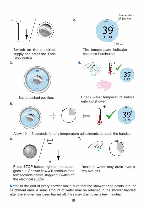
Turn control to full cold. The temperature will rise slightly as indicated by the temperature indicator.
0 - �0 Secs
12.11.10.
The flow rate will increase.
Ad jus t t empera tu re as required. Flow rate will adjust automatically.
5 - �0 Secs
13.
15.
14.
16.
Press STOP button, l ight on the temperature indicator dims to standby state. When the shower has stopped running the temperature display will only show the clock. The water flow will continue for a few seconds before stopping. Isolate power. Display will go blank.
Press the ‘Medium’ button, light on the button comes on
Press the ‘High’ button, light on the button comes on

�6
T h e w a r m e r t h e shower, the lower the flow rate and vice versa.
Heated water is produced by adjusting the flow of cold water passed through a heater tank.
The shower has three heater settings.
User.InstructionsHow.Your.Electric.Shower.Works
The shower will purge water from its tank for a few seconds.
Residual water may drain over a few minutes.
17. 18.
Note!.A slight hissing sound may be heard from the Mira Orbis during operation. High mains water pressure and high shower temperatures will affect the tone. This is quite normal in use.
0 - 5 Secs
The tempera tu re indicator shows the temperature of the shower.

�7
Water inlet pressure fluctuations due to other draw offs (e.g. flushing toilet). Shower temperature will be controlled to within ± �°C of the set temperature provided that the supply conditions remain within the required operating parameters (refer to section: ‘Specifications’).
For a cold shower select ‘Low’.For a summer warm shower select ‘Medium’.For a winter warm shower select ‘High’.
During extremes of mains water supply temperature, adjust heater setting to obtain a better showering temperature.
The.Effect.of.Seasonal.Changes
The.Effect.of.Other.Water.Devices
Example of how shower temperature stabilises due to pressure changes.

�8
Using.your.ShowerRead the section “Important Safety Information” first.
TemperatureLimit Indicator
Low FlowIndicator
Temperatureof Shower
Clock (hours/minutes)
Clock (seconds) Temperature Display(Backlit during operation)
Start/StopButton
Heater SettingsLow, Medium, High
Temperature Setting
19
Note!.At the end of every shower make sure that the shower head points into the catchment area. A small amount of water may be retained in the shower handset after the shower has been turned off. This may drain over a few minutes.
2.1.
Set to desired position.
3.
Residual water may drain over a few minutes.
7.
4.
Check water temperature before entering shower.
5.
Allow 10 - 15 seconds for any temperature adjustments to reach the handset.6.
Press STOP button, light on the button goes out. Shower flow will continue for a few seconds before stopping. Switch off the electrical supply.
Switch on the electrical supply and press the ‘Start/Stop’ button
The temperature indicator becomes illuminated.
Temperatureof Shower
Clock
�0
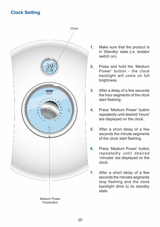
Clock.Setting
1. Make sure that the product is in ‘Standby’ state (i.e. Isolator switch on).
2. Press and hold the ‘Medium Power ’ button - the clock backlight will come on full brightness.
3. After a delay of a few seconds the hour segments of the clock start flashing
4. Press ‘Medium Power’ button repeatedly until desired ‘hours’ are displayed on the clock.
5. After a short delay of a few seconds the minute segments of the clock start flashing.
6. Press ‘Medium Power’ button repeatedly unt i l desi red ‘minutes’ are displayed on the clock.
7. After a short delay of a few seconds the minutes segments stop flashing and the clock backlight dims to its standby state.
Medium PowerPushbutton
Clock
��
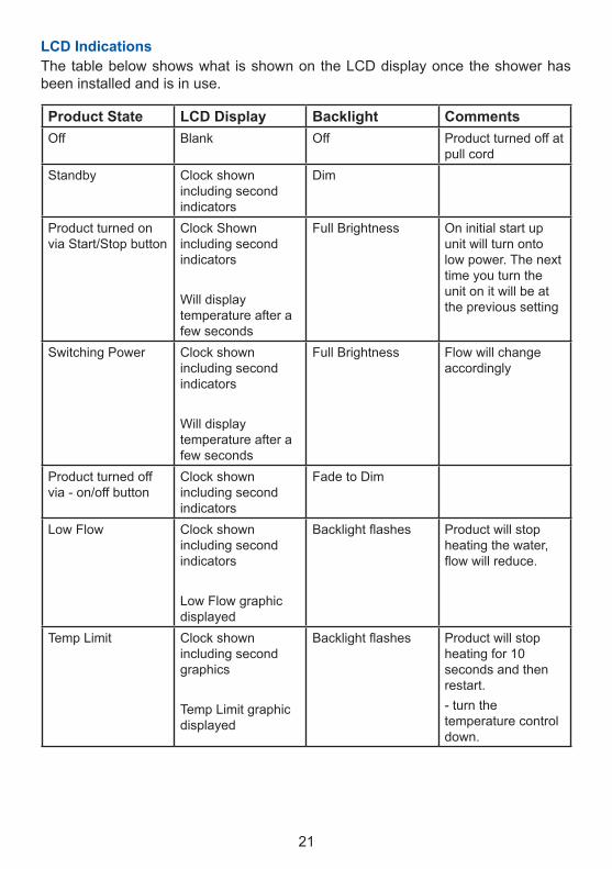
Product.State LCD.Display Backlight CommentsOff Blank Off Product turned off at
pull cordStandby Clock shown
including second indicators
Dim
Product turned on via Start/Stop button
Clock Shown including second indicators
Will display temperature after a few seconds
Full Brightness On initial start up unit will turn onto low power. The next time you turn the unit on it will be at the previous setting
Switching Power Clock shown including second indicators
Will display temperature after a few seconds
Full Brightness Flow will change accordingly
Product turned off via - on/off button
Clock shown including second indicators
Fade to Dim
Low Flow Clock shown including second indicators
Low Flow graphic displayed
Backlight flashes Product will stop heating the water, flow will reduce.
Temp Limit Clock shown including second graphics
Temp Limit graphic displayed
Backlight flashes Product will stop heating for �0 seconds and then restart.- turn the temperature control down.
LCD.IndicationsThe table below shows what is shown on the LCD display once the shower has been installed and is in use.
��
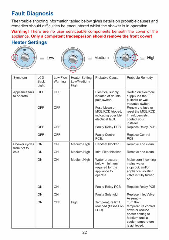
Fault.DiagnosisThe trouble shooting information tabled below gives details on probable causes and remedies should difficulties be encountered whilst the shower is in operation.Warning!. There are no user serviceable components beneath the cover of the appliance. Only.a.competent.tradesperson.should.remove.the.front.cover!Heater.Settings
Symptom LCD Back Light
Low Flow Warning
Heater Setting Low/Medium/High
Probable Cause Probable Remedy
Appliance fails to operate
OFF
OFF
OFF
OFF
OFF
OFF
OFF
OFF
Electrical supply isolated at double pole switch.
Fuse blown or MCB/RCD tripped, indicating possible electrical fault.
Faulty Relay PCB.
Faulty Control PCB.
Switch on electrical supply via the pullcord or wall mounted switch.Renew the fuse or reset the MCB/RCD. If fault persists, contact your installer.Replace Relay PCB.
Replace Control PCB.
Shower cycles from hot to cold
ON
ON
ON
ON
ON
ON
ON
ON
ON
ON
ON
OFF
Medium/High
Medium/High
Medium/High
High
Handset blocked.
Inlet Filter blocked.
Water pressure below minimum required for the appliance to operate.
Faulty Relay PCB.
Faulty Solenoid.
Temperature limit reached (flashes on LCD).
Remove and clean.
Remove and clean.
Make sure incoming mains water stopcock and/or appliance isolating valve is fully turned on.
Replace Relay PCB.
Replace Inlet Valve Assembly.Turn the temperature control down or reduce heater setting to Medium until a cooler temperature is achieved.
Low Medium High

�3
Symptom LCD BackLight
Low Flow Light
Heater SettingLow/Medium/High
Probable Cause Probable Remedy
Shower cycles form hot to cold
ON
ON
ON
OFF
OFF
OFF
Medium/High
Medium/High
Medium/High
Thermostatic mechanism is faulty or damaged.
Scaled Heater Tank Assy.
Damaged Hose.
Replace.
Replace.
Replace.
Handset dripping
OFF
OFF
OFF
OFF
Insufficient water supply pressure for shut off.
Inlet valve assembly faulty.
The minimum static pressure to ensure shut off and prevent dripping is 0.� bar.Note!.If other appliances are operating, static pressure may drop below 0.� bar. Contact local water company.
Replace.
Low or no flow rate
ON
OFF
OFF
OFF
ON
ON
ON
OFF
OFF
OFF
ON
OFF
Any
Any
Any
Water supply pipework or inlet filter restricted by a blockage or partial blockage.
Insufficient water supply pressure/flow for operation.
Faulty Relay PCB.
Faulty Control PCB.
Other outlets (e.g. toilet, garden hose, washing machine etc.) drawing water whilst the shower is being used.Hose Damaged.
Flush supply pipe. Clean inlet filter.
Contact local water company. Supply pressure must be a minimum of �00 kPa (1.0 bar). Note! If other appliances are operating, pressure may drop below �00 kPa (�.0 bar).
Replace Relay PCB.
Replace Control PCB.
Turn off the other appliances whilst the shower is in use.
Replace.
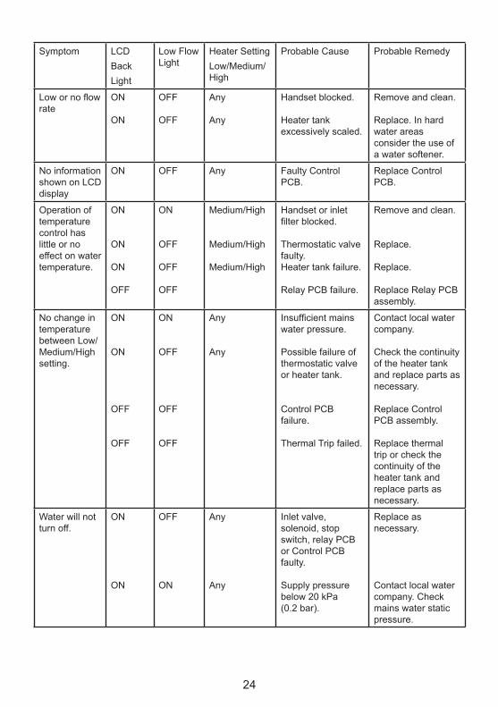
�4
Symptom LCDBackLight
Low Flow Light
Heater SettingLow/Medium/High
Probable Cause Probable Remedy
Low or no flow rate
ON
ON
OFF
OFF
Any
Any
Handset blocked.
Heater tank excessively scaled.
Remove and clean.
Replace. In hard water areas consider the use of a water softener.
No information shown on LCD display
ON OFF Any Faulty Control PCB.
Replace Control PCB.
Operation of temperature control has little or no effect on water temperature.
ON
ON
ON
OFF
ON
OFF
OFF
OFF
Medium/High
Medium/High
Medium/High
Handset or inlet filter blocked.
Thermostatic valve faulty.Heater tank failure.
Relay PCB failure.
Remove and clean.
Replace.
Replace.
Replace Relay PCB assembly.
No change in temperature between Low/Medium/High setting.
ON
ON
OFF
OFF
ON
OFF
OFF
OFF
Any
Any
Insufficient mains water pressure.
Possible failure of thermostatic valve or heater tank.
Control PCB failure.
Thermal Trip failed.
Contact local water company.
Check the continuity of the heater tank and replace parts as necessary.
Replace Control PCB assembly.
Replace thermal trip or check the continuity of the heater tank and replace parts as necessary.
Water will not turn off.
ON
ON
OFF
ON
Any
Any
Inlet valve, solenoid, stop switch, relay PCB or Control PCB faulty.
Supply pressure below �0 kPa (0.� bar).
Replace as necessary.
Contact local water company. Check mains water static pressure.

�5
Symptom LCDBackLight
Low Flow Light
Heater SettingLow/Medium/High
Probable Cause Probable Remedy
Appliance fails to produce hot water when set on ‘Medium/High’ heater setting.
ON
ON
ON
ON
OFF
OFF
Medium/High
Medium/High
Medium/High
Insufficient water supply.
Possible failure of the thermal switch.
Heater tank failure.
Contact local Water company.
Check the continuity of the heater tank and replace parts as necessary.
Replace.
Unable to select a cool enough shower.
ON OFF High Due to the rise in mains water supply temperature, the heater setting may be too high.
Press the ‘Medium’ heater setting and adjust the temperature control until a suitable temperature is reached.
Clock does not keep time
ON OFF Any Battery needs replacing.
Faulty Control board.
Replace battery.
Replace.
E� displayed on screen
ON OFF Any Check thermistor is plugged in.
Refit.

�6
Clean with mild washing up detergent or soap solution. Wipe dry with a soft cloth.
Poor shower performance can be avoided by cleaning the spray plate. Use thumb or soft cloth to wipe rubber nozzles. The handset must also be descaled regularly.
Make sure that the electrical supply is turned off at the mains and that the water supply is fully turned off.
Remove the three screws. Carefully remove the cover, making sure that you do not strain the multi-connector.
Carefully remove the multi-connector from the socket on the control PCB in the case. Remove the service tunnel.
Hold a wrench across the flats of the metal connector. Unscrew the filter using another wrench as shown. Clean or renew the Filter as necessary. Refit in reverse order making sure the Filter is screwed fully home.
Do not overtighten. Make sure plumbing connections are tight before restoring the electricity and water supply. Check for leaks.
Refit the Service Tunnel and connect the multi-connector to the socket on the PCB.
Refit the Cover. Make sure that it fits correctly. Do not overtighten screws.
Inlet Filter - Cleaning/RenewingRead the section “Important Safety Information” first
Cover
Cover RetainingScrew
Service Tunnel
Filter
MaintenanceHandset - Cleaning

�7
Clock.Battery.Replacement.ProcedureWarning!. There are no user serviceable components beneath the cover of the appliance. Only.a.competent.tradesperson.should.remove.the.front.cover!Read the section “Important Safety Information” first.
1. Isolate the electrical supply before commencing this procedure. The electricity must be turned off at the mains and the appropriate circuit fuse removed, if applicable.
2. Mains connections are exposed when the cover is removed.
Remove the three screws. Carefully remove the cover, making sure that you do not strain the multi-connector.
Carefully remove the multi-connector from the socket on the control PCB in the case. Remove the service tunnel.
Carefully remove the battery from the housing.
When. the. battery. has. reached. the.end.of.its.serviceable.life,.make.sure.the.battery. is.disposed.of. in.a.safe.manner,.in.accordance.with.current.local. authority. recycling,. or. waste.disposal.policy.
Refit a new battery.(Battery type BR �03� or CR�03�)
Connect the multi-connector to the socket on the PCB.
Refit the Cover. Make sure that it fits correctly. Do not overtighten the three cover retaining screws.Restore the electrical supply.
Reset the clock, refer to the ‘Clock Setting’ procedure.
�8
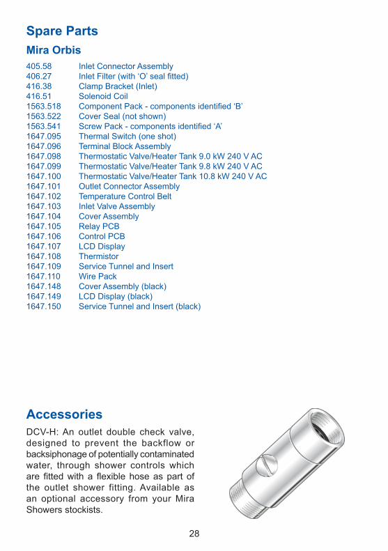
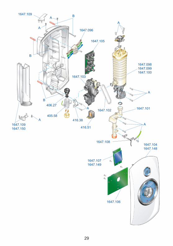
Spare.PartsMira.Orbis405.58 Inlet Connector Assembly406.27 Inlet Filter (with ‘O’ seal fitted)4�6.38 Clamp Bracket (Inlet)4�6.5� Solenoid Coil1563.518 Component Pack - components identified ‘B’�563.5�� Cover Seal (not shown)1563.541 Screw Pack - components identified ‘A’1647.095 Thermal Switch (one shot)1647.096 Terminal Block Assembly1647.098 Thermostatic Valve/Heater Tank 9.0 kW 240 V AC1647.099 Thermostatic Valve/Heater Tank 9.8 kW 240 V AC1647.100 Thermostatic Valve/Heater Tank 10.8 kW 240 V AC1647.101 Outlet Connector Assembly�647.�0� Temperature Control Belt1647.103 Inlet Valve Assembly1647.104 Cover Assembly�647.�05 Relay PCB�647.�06 Control PCB�647.�07 LCD Display�647.�08 Thermistor1647.109 Service Tunnel and Insert�647.��0 Wire Pack1647.148 Cover Assembly (black)1647.149 LCD Display (black)�647.�50 Service Tunnel and Insert (black)
AccessoriesDCV-H: An outlet double check valve, designed to prevent the backflow or backsiphonage of potentially contaminated water, through shower controls which are fitted with a flexible hose as part of the outlet shower fitting. Available as an optional accessory from your Mira Showers stockists.
29
�647.�06
�647.�071647.149
�647.�04�647.�48
1647.0981647.099�647.�00
A
�647.�0�
A
�647.�0�
�647.�08
4�6.5�
A
4�6.38
406.�7
405.58
�647.�03
�647.�05
1647.096
B
A
A
B
B
A1647.109�647.�50
1647.109
A

30
Dimensions
Wiring.Diagram

3�
Customer.ServicesSpare.PartsWe maintain an extensive stock of spares, and aim to provide support throughout the product’s expected life.Spares can be purchased from approved stockists or merchants (locations on request) or direct from Customer Services. Spares direct will normally be despatched within two working days. Payment can be made by Visa or Mastercard at the time of ordering. Should payment by cheque be preferred a pro-forma invoice will be sent.All spares are guaranteed for 12 months from the date of purchase. spares that have been supplied directly from us can be returned within one month from the date of purchase providing that they are in good order and the packaging unopened.Note! Returned spares will be subject to a �5% restocking charge and authorisation must be obtained before return, contact our Customer Services Team.Note! In the interests of safety, spares requiring exposure to mains voltages can only be sent to competent persons.
ServiceOur Service Force is available to provide a quality service at a reasonable cost. You will have the assurance of a Mira trained Engineer/Agent, genuine Mira spares and a �� month guarantee on the repair.Payment should be made directly to the Service Engineer/Agent, using Visa, MasterCard or a cheque supported by a banker’s card.
To.contact.usEngland,.Scotland,.Wales.and.Northern.IrelandMira.Showers.Customer.ServicesTelephone: 0870 �4� 0888 Mon. to Fri. 8:00 am to 5:30 pm 8:30 am to 3:30 pm SaturdayE-mail: [email protected]: 01242 282595By Post: Cromwell Road, Cheltenham, Gloucestershire, GL5� 5EP
EireModern.Plant.Ltd..(Dublin)Telephone: 01 459 1344 Mon. to Fri. 9:00 am - 5:00 pmE-mail: [email protected]: Dublin 01 459 2329Post: Otter House, Naas Road, Clondalkin, Dublin ��
Modern.Plant.Ltd..(Cork)Telephone: 021 496 8755 Mon. to Fri. 9:00 am - 5:00 pmE-mail: [email protected]: 021 496 8607Post: Tramore Road, Cork
Guarantee.of.QualityMira Showers guarantee your product against any defect in materials or workmanship for the period shown in the Guarantee Registration Document included with your shower.Alternatively, to confirm the applicable guarantee period please contact Customer Services.To validate the guarantee, please return your completed registration card.Within the guarantee period we will resolve defects, free of charge, by repairing or replacing parts or modules as we may choose.To be free of charge, service work must only be undertaken by Mira Showers or our Approved Agents.Service under this guarantee does not affect the expiry date.The guarantee on any exchanged parts or product, ends when the normal product guarantee period expires.
Not.covered.by.this.guaranteeDamage or defects arising from incorrect installation, improper use or lack of maintenance, including build-up of limescale.Damage or defects if the product is taken apart, repaired or modified by any person not authorised by Mira Showers or our Approved Agents.This guarantee is in addition to your statutory and other legal rights.
Before.using.your.showerPlease take the time to read and understand the operating and safety instructions detailed in this manual.
What.to.do.if.something.goes.wrongIf when you first use your shower and it doesn’t function correctly, first contact your installer to check that the installation and commissioning are satisfactory and in accordance with the instructions in this manual.Should this not resolve the difficulty, simply contact our Customer Services who will give every assistance, and if necessary arrange for our Service Engineer to visit.If later the performance of your shower declines, consult this manual to see whether simple home maintenance is required.Please call our Customer Services to talk the difficulty through, request service under guarantee if applicable, or take advantage of our comprehensive After-Sales Service.As part of our quality and training programme calls may be recorded or monitored.Our Customer Services Team is comprehensively trained to provide every assistance you may need: help and advice, spare parts or a service visit.
3�1075158-W2-A © Kohler Mira Limited, August 2007
Mira is a registered trade mark of Kohler Mira Limited.
The company reserves the right to alter product specifications
without notice.www.mirashowers.com


