56
These instructions must be left with the user Installation Guide Mira Platinum Dual
1 1199702-W2-G
These instructions must be left with the user
Installation Guide
Mira Platinum Dual
21199702-W2-G
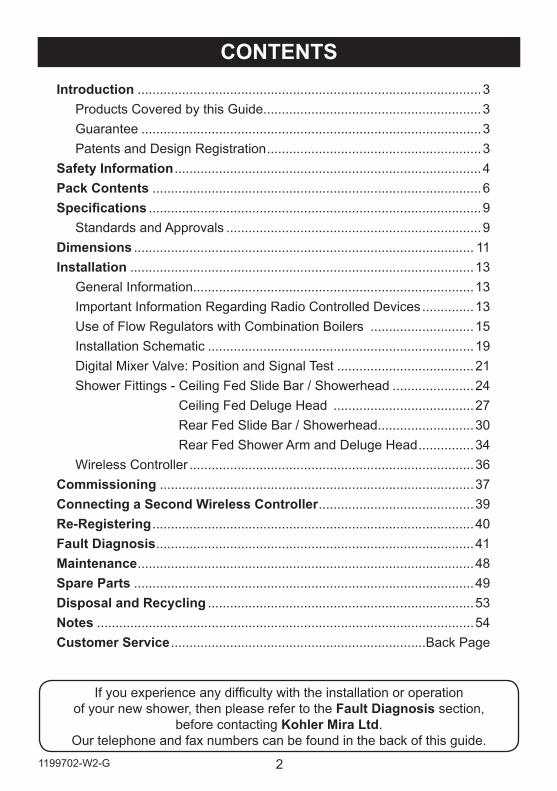
If you experience any difficulty with the installation or operation of your new shower, then please refer to the Fault Diagnosis section,
before contacting Kohler Mira Ltd. Our telephone and fax numbers can be found in the back of this guide.
CONTENTSIntroduction .............................................................................................3
Products Covered by this Guide...........................................................3Guarantee ............................................................................................3Patents and Design Registration ..........................................................3
Safety Information ...................................................................................4Pack Contents .........................................................................................6Specifications ..........................................................................................9
Standards and Approvals .....................................................................9Dimensions ............................................................................................ 11Installation .............................................................................................13
General Information ............................................................................13Important Information Regarding Radio Controlled Devices ..............13Use of Flow Regulators with Combination Boilers ............................15Installation Schematic ........................................................................19Digital Mixer Valve: Position and Signal Test .....................................21Shower Fittings - Ceiling Fed Slide Bar / Showerhead ......................24
Ceiling Fed Deluge Head ......................................27Rear Fed Slide Bar / Showerhead ..........................30Rear Fed Shower Arm and Deluge Head ...............34
Wireless Controller .............................................................................36Commissioning .....................................................................................37Connecting a Second Wireless Controller ..........................................39Re-Registering .......................................................................................40Fault Diagnosis ......................................................................................41Maintenance ...........................................................................................48Spare Parts ............................................................................................49Disposal and Recycling ........................................................................53Notes ......................................................................................................54Customer Service .....................................................................Back Page
3 1199702-W2-G
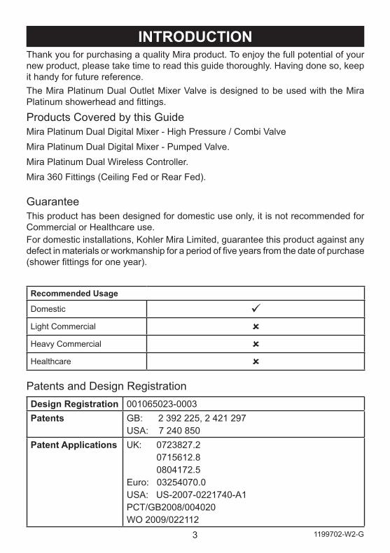
Thank you for purchasing a quality Mira product. To enjoy the full potential of your new product, please take time to read this guide thoroughly. Having done so, keep it handy for future reference.The Mira Platinum Dual Outlet Mixer Valve is designed to be used with the Mira Platinum showerhead and fittings.
Products Covered by this GuideMira Platinum Dual Digital Mixer - High Pressure / Combi ValveMira Platinum Dual Digital Mixer - Pumped Valve.Mira Platinum Dual Wireless Controller.Mira 360 Fittings (Ceiling Fed or Rear Fed).
Patents and Design RegistrationDesign Registration 001065023-0003Patents GB: 2 392 225, 2 421 297
USA: 7 240 850 Patent Applications UK: 0723827.2
0715612.8 0804172.5Euro: 03254070.0USA: US-2007-0221740-A1PCT/GB2008/004020WO 2009/022112
INTRODUCTION
Recommended Usage
Domestic Light Commercial Heavy Commercial Healthcare
GuaranteeThis product has been designed for domestic use only, it is not recommended for Commercial or Healthcare use.For domestic installations, Kohler Mira Limited, guarantee this product against any defect in materials or workmanship for a period of five years from the date of purchase (shower fittings for one year).
41199702-W2-G
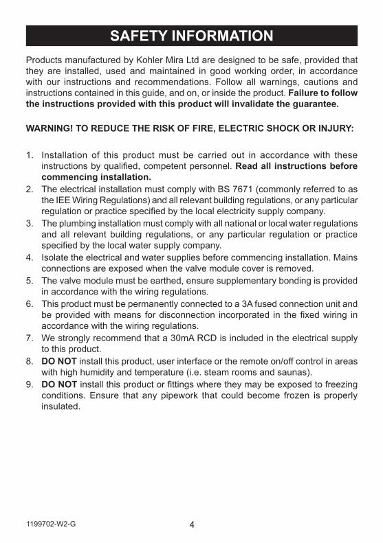
SAFETY INFORMATIONProducts manufactured by Kohler Mira Ltd are designed to be safe, provided that they are installed, used and maintained in good working order, in accordance with our instructions and recommendations. Follow all warnings, cautions and instructions contained in this guide, and on, or inside the product. Failure to follow the instructions provided with this product will invalidate the guarantee.
WARNING! TO REDUCE THE RISK OF FIRE, ELECTRIC SHOCK OR INJURY:
1. Installation of this product must be carried out in accordance with these instructions by qualified, competent personnel. Read all instructions before commencing installation.
2. The electrical installation must comply with BS 7671 (commonly referred to as the IEE Wiring Regulations) and all relevant building regulations, or any particular regulation or practice specified by the local electricity supply company.
3. The plumbing installation must comply with all national or local water regulations and all relevant building regulations, or any particular regulation or practice specified by the local water supply company.
4. Isolate the electrical and water supplies before commencing installation. Mains connections are exposed when the valve module cover is removed.
5. The valve module must be earthed, ensure supplementary bonding is provided in accordance with the wiring regulations.
6. This product must be permanently connected to a 3A fused connection unit and be provided with means for disconnection incorporated in the fixed wiring in accordance with the wiring regulations.
7. We strongly recommend that a 30mA RCD is included in the electrical supply to this product.
8. DO NOT install this product, user interface or the remote on/off control in areas with high humidity and temperature (i.e. steam rooms and saunas).
9. DO NOT install this product or fittings where they may be exposed to freezing conditions. Ensure that any pipework that could become frozen is properly insulated.
5 1199702-W2-G
10. DO NOT perform any unspecified modifications, drill or cut holes in the product other than instructed by this guide. When servicing only use genuine Kohler Mira replacement parts.
11. If the product is dismantled during installation or servicing then, upon completion, an inspection must be made to ensure all
12. DO NOT operate the product if water is leaking from inside the valve module. Isolate electrical and water supplies to the product and refer to the fault diagnosis section.
13. DO NOT apply power to the product if it is thought to have been exposed to freezing conditions. Isolate electrical and water supplies to the product and contact Kohler Mira Ltd.
14. Make sure that you fully understand how to operate the product and make sure that it is properly maintained in accordance with the instructions given in this manual.
15. This product can be used by children aged from 8 years and above and persons with reduced physical, sensory or mental capabilities or lack of experience and knowledge if they have been given supervision or instruction concerning the use of the product in a safe way and understand the hazards involved.
16. DO NOT allow children to play with the product.17. DO NOT allow children to clean or perform any user maintenance without
supervision.18. Always check the water temperature is safe before bathing or showering.19. When installing the product to be used as a bath filler ensure the flow rate of the
bath overflow fitted exceeds the flow rate output from the product.20. DO NOT remotely operate or alter any of this products shower and bathing
settings if it is already occupied and / or being used by another person.
61199702-W2-G
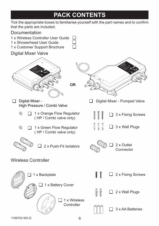
PACK CONTENTS
Digital Mixer Valve
Wireless Controller
Tick the appropriate boxes to familiarise yourself with the part names and to confirm that the parts are included.Documentation1 x Wireless Controller User Guide1 x Showerhead User Guide1 x Customer Support Brochure
2 x Push-Fit Isolators
OR
Digital Mixer - High Pressure / Combi Valve
3 x Fixing Screws
3 x Wall Plugs
2 x Outlet Connector
Digital Mixer - Pumped Valve
1 x Orange Flow Regulator ( HP / Combi valve only)
1 x Green Flow Regulator ( HP / Combi valve only)
2 x Fixing Screws
2 x Wall Plugs
1 x Wireless Controller
1 x Backplate
3 x AA Batteries
1 x Battery Cover
7 1199702-W2-G
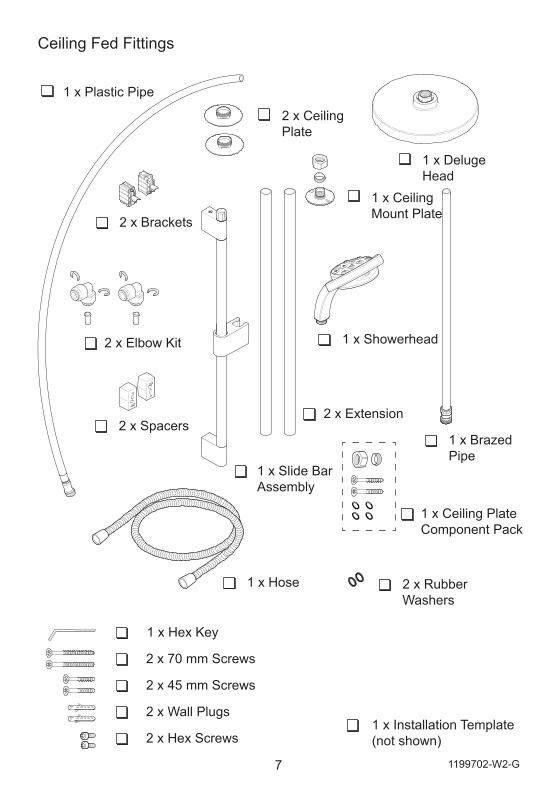
Ceiling Fed Fittings
2 x Ceiling Plate
2 x Elbow Kit
2 x Extension
1 x Slide Bar Assembly
2 x Hex Screws
2 x Wall Plugs
2 x 45 mm Screws
1 x Hex Key
2 x 70 mm Screws
1 x Installation Template (not shown)
1 x Ceiling Mount Plate
1 x Brazed Pipe
1 x Showerhead
2 x Rubber Washers
1 x Hose
1 x Deluge Head
1 x Plastic Pipe
2 x Brackets
1 x Ceiling Plate Component Pack
2 x Spacers
81199702-W2-G
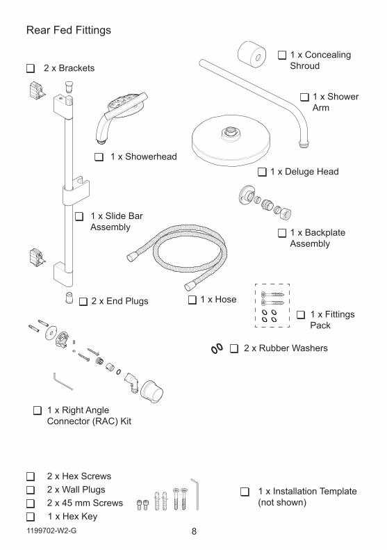
Rear Fed Fittings
2 x End Plugs
2 x Brackets
1 x Showerhead
1 x Slide Bar Assembly
2 x Rubber Washers
1 x Hose
1 x Right Angle Connector (RAC) Kit
1 x Installation Template(not shown)
2 x Hex Screws2 x Wall Plugs2 x 45 mm Screws1 x Hex Key
1 x Deluge Head
1 x Backplate Assembly
1 x Shower Arm
1 x Concealing Shroud
1 x Fittings Pack
9 1199702-W2-G
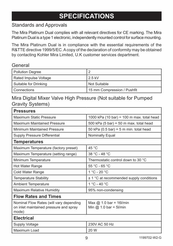
SPECIFICATIONSStandards and ApprovalsThe Mira Platinum Dual complies with all relevant directives for CE marking. The Mira Platinum Dual is a type 1 electronic, independently mounted control for surface mounting.
The Mira Platinum Dual is in compliance with the essential requirements of the R&TTE directive 1999/5/EC. A copy of the declaration of conformity may be obtained by contacting Kohler Mira Limited, U.K customer services department.
GeneralPollution Degree 2Rated Impulse Voltage 2.5 kVSuitable for Drinking Not SuitableConnections 15 mm Compression / Pushfit
Mira Digital Mixer Valve High Pressure (Not suitable for Pumped Gravity Systems)PressuresMaximum Static Pressure 1000 kPa (10 bar) = 100 m max. total headMaximum Maintained Pressure 500 kPa (5 bar) = 50 m max. total headMinimum Maintained Pressure 50 kPa (0.5 bar) = 5 m min. total headSupply Pressure Differential Nominally Equal
TemperaturesMaximum Temperature (factory preset) 45 °CMaximum Temperature (setting range) 38 °C - 48 °CMinimum Temperature Thermostatic control down to 30 °CHot Water Range 55 °C - 65 °CCold Water Range 1 °C - 20 °CTemperature Stability ± 1 °C at recommended supply conditionsAmbient Temperature 1 °C - 40 °CMaximum Relative Humidity 95% non-condensing
Flow Rates and TimesNominal Flow Rates (will vary depending on inlet maintained pressure and spray mode)
Max @ 1.0 bar = 16l/minMin @ 1.0 bar = 5l/min
ElectricalSupply Voltage 230V AC 50 HzMaximum Load 20 W
101199702-W2-G
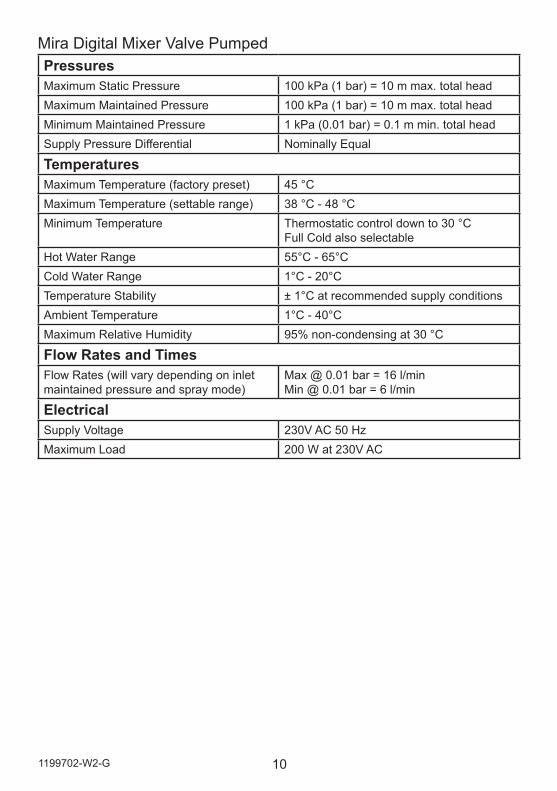
Mira Digital Mixer Valve PumpedPressuresMaximum Static Pressure 100 kPa (1 bar) = 10 m max. total headMaximum Maintained Pressure 100 kPa (1 bar) = 10 m max. total headMinimum Maintained Pressure 1 kPa (0.01 bar) = 0.1 m min. total headSupply Pressure Differential Nominally Equal
TemperaturesMaximum Temperature (factory preset) 45 °CMaximum Temperature (settable range) 38 °C - 48 °CMinimum Temperature Thermostatic control down to 30 °C
Full Cold also selectable Hot Water Range 55°C - 65°CCold Water Range 1°C - 20°CTemperature Stability ± 1°C at recommended supply conditionsAmbient Temperature 1°C - 40°CMaximum Relative Humidity 95% non-condensing at 30 °C
Flow Rates and TimesFlow Rates (will vary depending on inlet maintained pressure and spray mode)
Max @ 0.01 bar = 16 l/minMin @ 0.01 bar = 6 l/min
ElectricalSupply Voltage 230V AC 50 HzMaximum Load 200 W at 230V AC
11 1199702-W2-G
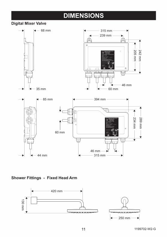
DIMENSIONS
FOR HIGH PRESSURE / COMBINATION BOILERPART No. 1796.011N85KMANUFACTURED DATE:
KOHLER MIRA LTD.CHELTENHAMGL52 5EPTEL: (+44) 0870 241 0888
www.mirashowers.co.uk
HOT COLD
POWER: 230V ~ 20WPROTECTION: IP24MIN. SUPPLY PRESSURE: 50 kPa (0.5 bar)MAX. WORKING PRESSURE: 500 kPa (5 bar)MAX. STATIC PRESSURE: 1000 kPa (10 bar) (WRAS)MAX. SUPPLY WATER TEMP: 65 °C
MOUNTING POSITION
VERTICAL HORIZONTAL
OR
ISOLATE MAINS ELECTRICITY BEFORE REMOVING COVER!
F14319/1
DUAL OUTLETDIGITAL MIXER
FOR LOW PRESSURE SYSTEMSPART No. 1796.010N85LMANUFACTURED DATE:
KOHLER MIRA LTD.CHELTENHAMGL52 5EPTEL: (+44) 0870 241 0888
www.mirashowers.co.uk
POWER: 230V ~ 200WPROTECTION: IP24MIN. SUPPLY HEAD: 0.1 m (0.01 bar)MAX. WORKING HEAD: 10 m (1 bar)MAX. SUPPLY WATER TEMP: 65 °C
MOUNTING POSITION
VERTICAL HORIZONTAL
OR
ISOLATE MAINS ELECTRICITY BEFORE REMOVING COVER!
F14318/1
DUAL OUTLETDIGITAL MIXER
HOT COLD
46 mm60 mm
60 mm
85 mm
35 mm
68 mm
44 mm46 mm
130 mm
Digital Mixer Valve
Shower Fittings - Fixed Head Arm
315 mm239 mm
205 mm
242 mm
394 mm
234 mm
289 mm
315 mm
420 mm
250 mm
121199702-W2-G
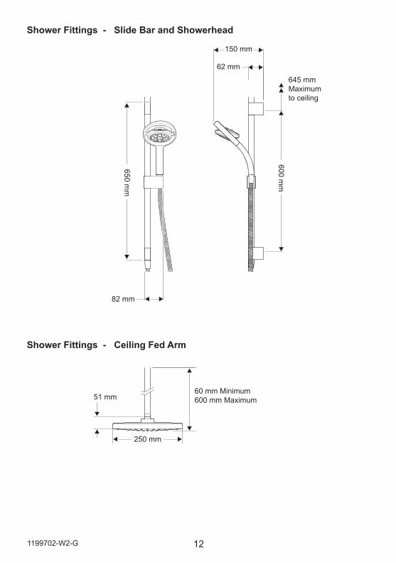
Shower Fittings - Slide Bar and Showerhead
Shower Fittings - Ceiling Fed Arm
250 mm
600 mm
650 mm
82 mm
150 mm
62 mm
645 mm Maximum to ceiling
60 mm Minimum600 mm Maximum51 mm
13 1199702-W2-G
INSTALLATION
Important Information Regarding Radio Controlled Devices• Metal objects such as steel baths or sinks, cold water storage tanks, hot water
cylinders, foil lined plaster board walls, radiators and even thick brick walls, can all dramatically reduce the radio operational range of any radio controlled product.
• Interference from other radio signals can dramatically reduce the ability of the Platinum Wireless Controller / digital mixer to register or communicate. This may include; mobile phones, radio control boiler thermostats, wireless broadband routers, radio control toys, cordless phones, remote outdoor weather stations, wireless doorbells etc.
• If you encounter difficulty registering the wireless controller and digital mixer ensure all other radio interference is temporarily switched off.
Note! Failure to follow these guidelines can result in poor, intermittent or complete failure to communicate with the digital mixer.
Note! Both the Wireless Controller and Digital Mixer contain internal radio transmission aerials which are directional in operation. In order to achieve optimum radio signal strength and therefore optimum communication distance It may be necessary to alter the Wireless Controller and Digital Mixer relative orientation /position to each other.
General InformationThe product may be installed in a loft space, under the bath or in a convenient cupboard space, provided there is enough room for maintenance (e.g. Removal of the product lid). Failure to do so may result in an inability to carry out any maintenance.
Safe and easy access to the product should be available at all times.
When installing the product in an area not regularly accessed, consideration for potential leaks must be taken into account. While such events are unlikely, it is advisable to periodically check the installation for traces of water on or around the product.
If possible, site the product in a location where any leak would be contained or routed to avoid areas sensitive to water damage.
Inlet isolating valves (supplied) must be installed.
We strongly recommend that full bore outlet isolation valves are fitted as close to the product as possible for ease of service and maintenance.
The water supplies to this product must be isolated if the product is not to be used for a long period of time. If the product or pipework is at risk of freezing during this period they should also be drained of water.
141199702-W2-G
Typical Suitable Installations:
Mira Platinum Shower Fittings
Deluge Head
Digital Mixer Valve (HP) Key to Symbols
CombinationBoiler
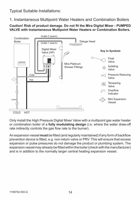
1. Instantaneous Multipoint Water Heaters and Combination BoilersCaution! Risk of product damage. Do not fit the Mira Digital Mixer - PUMPED VALVE with Instantaneous Multipoint Water Heaters or Combination Boilers.
Cold
Hot
FOR HIGH PRESSURE / COMBINATION BOILERPART No. 1796.011N85KMANUFACTURED DATE:
KOHLER MIRA LTD.CHELTENHAMGL52 5EPTEL: (+44) 0870 241 0888
www.mirashowers.co.uk
HOT COLD
POWER: 230V ~ 20WPROTECTION: IP24MIN. SUPPLY PRESSURE: 50 kPa (0.5 bar)MAX. WORKING PRESSURE: 500 kPa (5 bar)MAX. STATIC PRESSURE: 1000 kPa (10 bar) (WRAS)MAX. SUPPLY WATER TEMP: 65 °C
MOUNTING POSITION
VERTICAL HORIZONTAL
OR
ISOLATE MAINS ELECTRICITY BEFORE REMOVING COVER!
F14319/1
DUAL OUTLETDIGITAL MIXER
Outlet 1 (warm)
Outlet 2 (warm)
Float Valve
Isolating Valve
Tempering ValveOverflow Indicator
Mini Expansion Vessel
Pressure Reducing Valve
COLD HOT
Only install the High Pressure Digital Mixer Valve with a multipoint gas water heater or combination boiler of a fully modulating design (i.e. where the water draw-off rate indirectly controls the gas flow rate to the burner).
An expansion vessel must be fitted (and regularly maintained) if any form of backflow prevention device is fitted, e.g. non-return valve or PRV. This will ensure that excess expansion or pulse pressures do not damage the product or plumbing system. The expansion vessel may already be fitted within the boiler (check with the manufacturer) and is in addition to the normally larger central heating expansion vessel.
15 1199702-W2-G
Use of Flow Regulators with Combination Boilers The Mira Digital Mixer Valve can demand hot water quicker than some instantaneous water heaters/combination boilers can provide, especially in winter when the mains water is colder. A Hot inlet flow regulator may need to be used to ensure that the Digital Mixer Valve can deliver a full range of water temperatures.
Note:The Mira Single outlet digital mixing valves are factory fitted with an 8 l/min hot inlet flow regulator. If installing a single outlet digital mixer with a combi boiler rated 36kW or greater or to mains pressurised systems the hot inlet flow regulator should be removed.
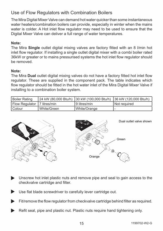
Note:The Mira Dual outlet digital mixing valves do not have a factory fitted hot inlet flow regulator. These are supplied in the component pack. The table indicates which flow regulator should be fitted in the hot water inlet of the Mira Digital Mixer Valve if installing to a combination boiler system.
Unscrew hot inlet plastic nuts and remove pipe and seal to gain access to the checkvalve cartridge and filter.
Use flat blade screwdriver to carefully lever cartridge out.
Fit/remove the flow regulator from checkvalve cartridge behind filter as required.
Refit seal, pipe and plastic nut. Plastic nuts require hand tightening only.
Green
Orange
Dual outlet valve shown
Boiler Rating 24 kW (80,000 Btu/h) 30 kW (100,000 Btu/h) 36 kW (120,000 Btu/h)Flow Regulator 7 litres/min 9 litres/min Not requiredColour White/Green White/Orange -
161199702-W2-G
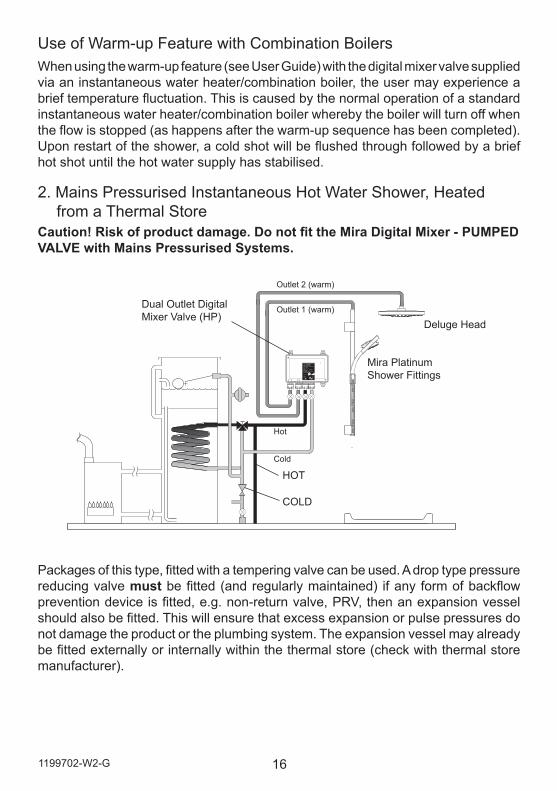
Packages of this type, fitted with a tempering valve can be used. A drop type pressure reducing valve must be fitted (and regularly maintained) if any form of backflow prevention device is fitted, e.g. non-return valve, PRV, then an expansion vessel should also be fitted. This will ensure that excess expansion or pulse pressures do not damage the product or the plumbing system. The expansion vessel may already be fitted externally or internally within the thermal store (check with thermal store manufacturer).
2. Mains Pressurised Instantaneous Hot Water Shower, Heated from a Thermal Store
Caution! Risk of product damage. Do not fit the Mira Digital Mixer - PUMPED VALVE with Mains Pressurised Systems.
COLD
HOT
FOR HIGH PRESSURE / COMBINATION BOILERPART No. 1796.011N85KMANUFACTURED DATE:
KOHLER MIRA LTD.CHELTENHAMGL52 5EPTEL: (+44) 0870 241 0888
www.mirashowers.co.uk
HOT COLD
POWER: 230V ~ 20WPROTECTION: IP24MIN. SUPPLY PRESSURE: 50 kPa (0.5 bar)MAX. WORKING PRESSURE: 500 kPa (5 bar)MAX. STATIC PRESSURE: 1000 kPa (10 bar) (WRAS)MAX. SUPPLY WATER TEMP: 65 °C
MOUNTING POSITION
VERTICAL HORIZONTAL
OR
ISOLATE MAINS ELECTRICITY BEFORE REMOVING COVER!
F14319/1
DUAL OUTLETDIGITAL MIXER
Outlet 1 (warm)
Outlet 2 (warm)
Hot
Cold
Dual Outlet Digital Mixer Valve (HP)
Mira Platinum Shower Fittings
Deluge Head
Use of Warm-up Feature with Combination BoilersWhen using the warm-up feature (see User Guide) with the digital mixer valve supplied via an instantaneous water heater/combination boiler, the user may experience a brief temperature fluctuation. This is caused by the normal operation of a standard instantaneous water heater/combination boiler whereby the boiler will turn off when the flow is stopped (as happens after the warm-up sequence has been completed). Upon restart of the shower, a cold shot will be flushed through followed by a brief hot shot until the hot water supply has stabilised.
17 1199702-W2-G
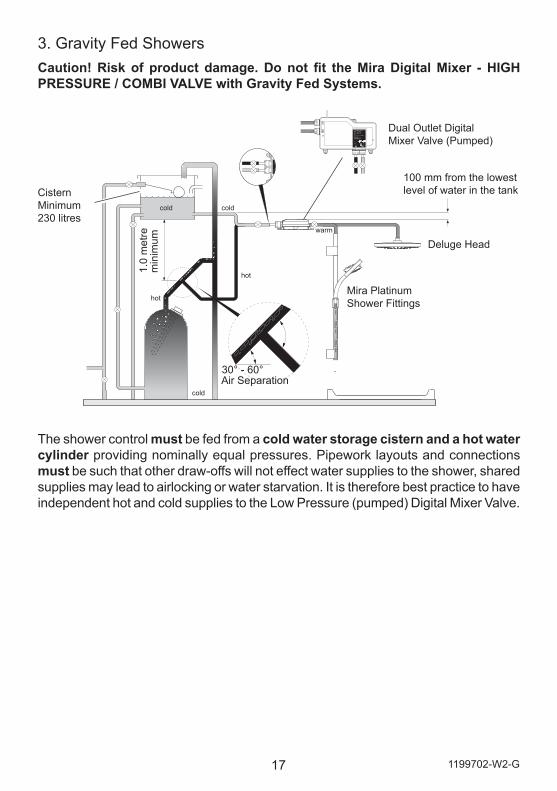
3. Gravity Fed ShowersCaution! Risk of product damage. Do not fit the Mira Digital Mixer - HIGH PRESSURE / COMBI VALVE with Gravity Fed Systems.
The shower control must be fed from a cold water storage cistern and a hot water cylinder providing nominally equal pressures. Pipework layouts and connections must be such that other draw-offs will not effect water supplies to the shower, shared supplies may lead to airlocking or water starvation. It is therefore best practice to have independent hot and cold supplies to the Low Pressure (pumped) Digital Mixer Valve.
MIR
A DM
2 WIR
ELESS H
P/CO
MB
I1666.009N
85AM
AN
UFA
CTU
RED
KO
HLE
R M
IRA LTD
.C
HE
LTEN
HA
MG
L52 5EP
TEL: (+44) 0870 241 0888
ww
w.m
irashowers.com
HO
TC
OLD
POW
ER: 230 V A
C 20 W
PRO
TECTIO
N: IP24
MIN
. SUPPLY PR
ESSUR
E: 50 kPa (0.5 bar)M
AX. W
OR
KIN
G PR
ESSUR
E: 500 kPa (5 bar)M
AX. STATIC
PRESSU
RE: 1000 kPa (10 bar) (W
RA
S)M
AX. SU
PPLY WATER
TEMP: 65 °C
POSITIO
N A
PPLIAN
CE
OR
ISOLATE M
AIN
S ELECTR
ICITY B
EFOR
E R
EMO
VING
CO
VER!
F9001
DIG
ITAL M
IXER 2 W
IRELESS
cold
coldcold
warm
hot
hot
100 mm from the lowest level of water in the tankCistern
Minimum 230 litres
Mira Platinum Shower Fittings
Deluge Head
1.0
met
re
min
imum
30° - 60°Air Separation
FOR LOW PRESSURE SYSTEMSPART No. 1796.010N85LMANUFACTURED DATE:
KOHLER MIRA LTD.CHELTENHAMGL52 5EPTEL: (+44) 0870 241 0888
www.mirashowers.co.uk
POWER: 230V ~ 200WPROTECTION: IP24MIN. SUPPLY HEAD: 0.1 m (0.01 bar)MAX. WORKING HEAD: 10 m (1 bar)MAX. SUPPLY WATER TEMP: 65 °C
MOUNTING POSITION
VERTICAL HORIZONTAL
OR
ISOLATE MAINS ELECTRICITY BEFORE REMOVING COVER!
F14318/1
DUAL OUTLETDIGITAL MIXER
HOT COLD
Dual Outlet Digital Mixer Valve (Pumped)
181199702-W2-G
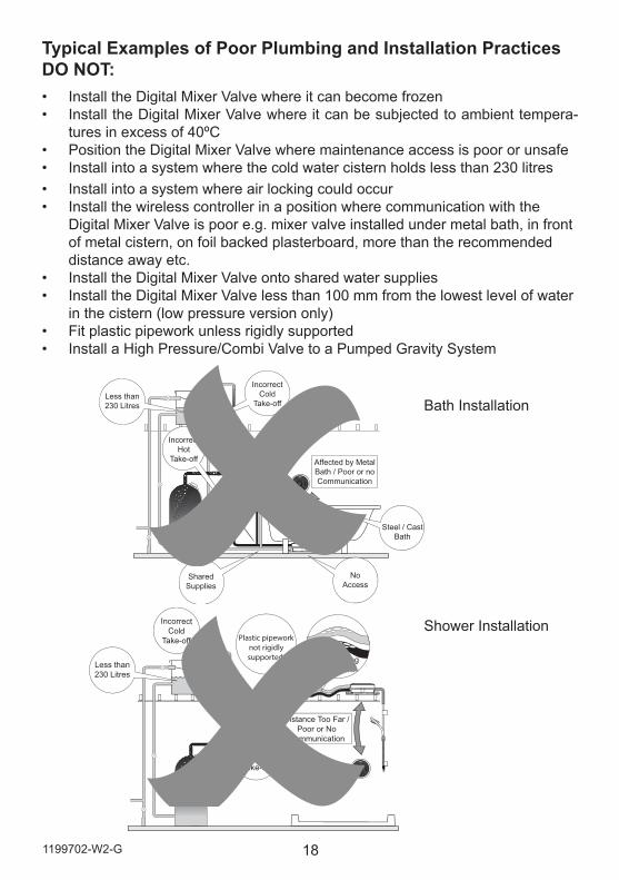
Typical Examples of Poor Plumbing and Installation PracticesDO NOT:• Install the Digital Mixer Valve where it can become frozen• Install the Digital Mixer Valve where it can be subjected to ambient tempera-
tures in excess of 40ºC• Position the Digital Mixer Valve where maintenance access is poor or unsafe• Install into a system where the cold water cistern holds less than 230 litres• Install into a system where air locking could occur• Install the wireless controller in a position where communication with the
Digital Mixer Valve is poor e.g. mixer valve installed under metal bath, in front of metal cistern, on foil backed plasterboard, more than the recommended distance away etc.
• Install the Digital Mixer Valve onto shared water supplies• Install the Digital Mixer Valve less than 100 mm from the lowest level of water
in the cistern (low pressure version only)• Fit plastic pipework unless rigidly supported• Install a High Pressure/Combi Valve to a Pumped Gravity System
Shower Installation
Bath Installation
Affected by MetalBath / Poor or noCommunication
SharedSupplies
NoAccess
Steel / CastBath
Less than230 Litres
IncorrectCold
Take-off
IncorrectHot
Take-off
1 2
Air-lockingPipework
Distance Too Far /Poor or No
Communication
Less than230 Litres
IncorrectCold
Take-off
IncorrectHot
Take-off
Plastic pipeworknot rigidlysupported.
1 2
19 1199702-W2-G
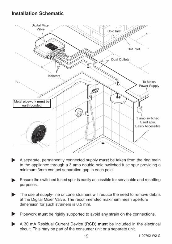
Installation Schematic
Cold Inlet
Isolators
Dual Outlets
Digital Mixer Valve
Hot Inlet
Metal pipework must be earth bonded
3 amp switched fused spur.
Easily Accessible
A separate, permanently connected supply must be taken from the ring main to the appliance through a 3 amp double pole switched fuse spur providing a minimum 3mm contact separation gap in each pole.
Ensure the switched fused spur is easily accessible for servicable and resetting purposes.
The use of supply-line or zone strainers will reduce the need to remove debris at the Digital Mixer Valve. The recommended maximum mesh aperturedimension for such strainers is 0.5 mm.
Pipework must be rigidly supported to avoid any strain on the connections.
A 30 mA Residual Current Device (RCD) must be included in the electrical circuit. This may be part of the consumer unit or a separate unit.
To Mains Power Supply
201199702-W2-G
Long inlet pipework (dead-legs) should be kept to a minimum to avoid temperature fluctuations.
Supply pipework layout must be arranged to minimize the effect of other outlet usage upon the dynamic pressures at the Digital Mixer Valve inlets.
To eliminate pipe debris it is essential that supply pipes are thoroughly flushed through before connection to the Digital Mixer Valve.
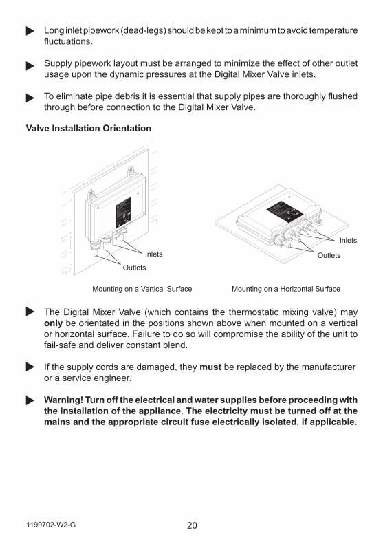
Mounting on a Vertical Surface
Inlets
Outlets
Inlets
Outlets
Mounting on a Horizontal Surface
The Digital Mixer Valve (which contains the thermostatic mixing valve) may only be orientated in the positions shown above when mounted on a vertical or horizontal surface. Failure to do so will compromise the ability of the unit to fail-safe and deliver constant blend.
If the supply cords are damaged, they must be replaced by the manufactureror a service engineer.
Warning! Turn off the electrical and water supplies before proceeding with the installation of the appliance. The electricity must be turned off at the mains and the appropriate circuit fuse electrically isolated, if applicable.
Valve Installation Orientation
21 1199702-W2-G
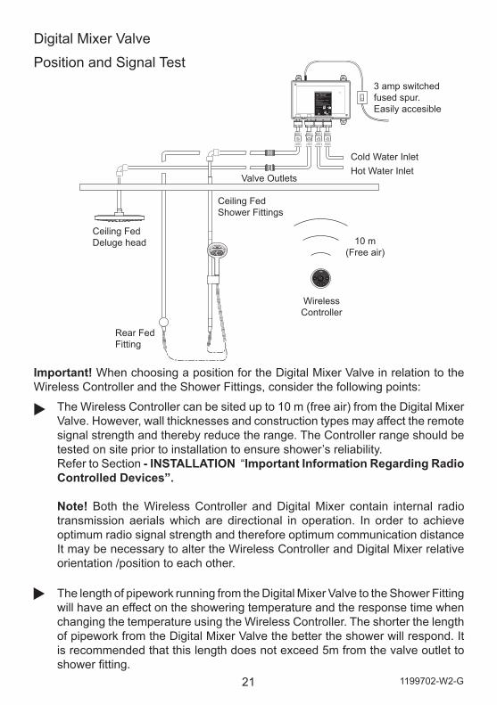
Important! When choosing a position for the Digital Mixer Valve in relation to the Wireless Controller and the Shower Fittings, consider the following points:
The Wireless Controller can be sited up to 10 m (free air) from the Digital Mixer Valve. However, wall thicknesses and construction types may affect the remote signal strength and thereby reduce the range. The Controller range should be tested on site prior to installation to ensure shower’s reliability. Refer to Section - INSTALLATION “Important Information Regarding Radio Controlled Devices”.
Note! Both the Wireless Controller and Digital Mixer contain internal radio transmission aerials which are directional in operation. In order to achieve optimum radio signal strength and therefore optimum communication distance It may be necessary to alter the Wireless Controller and Digital Mixer relative orientation /position to each other.
The length of pipework running from the Digital Mixer Valve to the Shower Fitting will have an effect on the showering temperature and the response time when changing the temperature using the Wireless Controller. The shorter the length of pipework from the Digital Mixer Valve the better the shower will respond. It is recommended that this length does not exceed 5m from the valve outlet to shower fitting.
Digital Mixer Valve
Position and Signal Test
FOR HIGH PRESSURE / COMBINATION BOILERPART No. 1796.011N85KMANUFACTURED DATE:
KOHLER MIRA LTD.CHELTENHAMGL52 5EPTEL: (+44) 0870 241 0888
www.mirashowers.co.uk
HOT COLD
POWER: 230V ~ 20WPROTECTION: IP24MIN. SUPPLY PRESSURE: 50 kPa (0.5 bar)MAX. WORKING PRESSURE: 500 kPa (5 bar)MAX. STATIC PRESSURE: 1000 kPa (10 bar) (WRAS)MAX. SUPPLY WATER TEMP: 65 °C
MOUNTING POSITION
VERTICAL HORIZONTAL
OR
ISOLATE MAINS ELECTRICITY BEFORE REMOVING COVER!
F14319/1
DUAL OUTLETDIGITAL MIXER
1 2
Valve Outlets
Cold Water InletHot Water Inlet
Wireless Controller
Rear FedFitting
Ceiling Fed Shower Fittings
Ceiling Fed Deluge head 10 m
(Free air)
3 amp switched fused spur.Easily accesible
221199702-W2-G
The ambient temperature of Digital Mixer Valve site (loft space, airing cupboard etc...) can have an effect on showering temperature. Insulate all pipework as required, particularly from the Digital Mixer Valve to the Shower Fitting.
The temperature indicated on the wireless controller display is measured inside the digital mixing valve and due to site conditions is not necessarily the temperature delivered at the shower outlet.
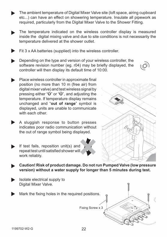
Fit 3 x AA batteries (supplied) into the wireless controller.
Depending on the type and version of your wireless controller, the software revision number (eg. r04) may be briefly displayed, the controller will then display its default time of 10:00.
Place wireless controller in approximate final position (no more than 10 m (free air) from digital mixer valve) and test wireless signal by pressing either “ 1 ” or “ 2 ”, and adjusting the temperature. If temperature display remains unchanged and “out of range” symbol is displayed, units are unable to communicate with each other.
A sluggish response to button presses indicates poor radio communication without the out of range symbol being displayed.
If test fails, reposition unit(s) and repeat test until satisfied shower will work reliably.
Caution! Risk of product damage. Do not run Pumped Valve (low pressure version) without a water supply for longer than 5 minutes during test.
Isolate electrical supply to Digital Mixer Valve.
Mark the fixing holes in the required positions.
Fixing Screw x 3
23 1199702-W2-G
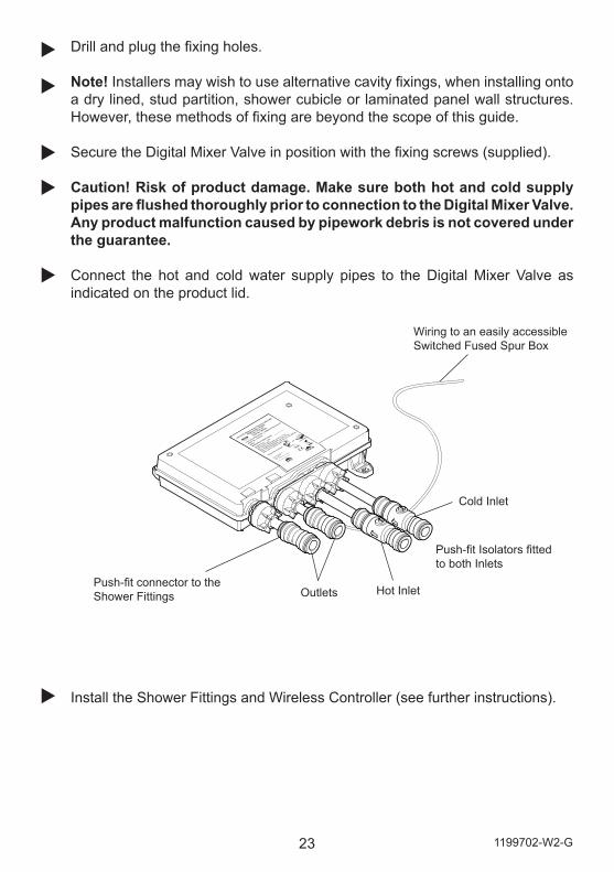
Drill and plug the fixing holes.
Note! Installers may wish to use alternative cavity fixings, when installing onto a dry lined, stud partition, shower cubicle or laminated panel wall structures. However, these methods of fixing are beyond the scope of this guide.
Secure the Digital Mixer Valve in position with the fixing screws (supplied).
Caution! Risk of product damage. Make sure both hot and cold supply pipes are flushed thoroughly prior to connection to the Digital Mixer Valve. Any product malfunction caused by pipework debris is not covered under the guarantee.
Connect the hot and cold water supply pipes to the Digital Mixer Valve as indicated on the product lid.
Install the Shower Fittings and Wireless Controller (see further instructions).
Push-fit connector to the Shower Fittings Outlets
Cold Inlet
Hot Inlet
Push-fit Isolators fitted to both Inlets
Wiring to an easily accessible Switched Fused Spur Box
241199702-W2-G
Shower Fittings - Ceiling Fed
Optional spacers (supplied)
600 mm
645 mm
Max.
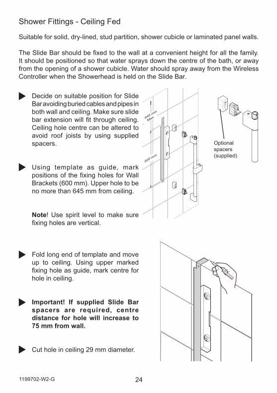
Decide on suitable position for Slide Bar avoiding buried cables and pipes in both wall and ceiling. Make sure slide bar extension will fit through ceiling. Ceiling hole centre can be altered to avoid roof joists by using supplied spacers.
Using template as guide, mark positions of the fixing holes for Wall Brackets (600 mm). Upper hole to be no more than 645 mm from ceiling.
Note! Use spirit level to make sure fixing holes are vertical.
Fold long end of template and move up to ceiling. Using upper marked fixing hole as guide, mark centre for hole in ceiling.
Important! If supplied Slide Bar spacers are required, centre distance for hole will increase to 75 mm from wall.
Cut hole in ceiling 29 mm diameter.
Suitable for solid, dry-lined, stud partition, shower cubicle or laminated panel walls.
The Slide Bar should be fixed to the wall at a convenient height for all the family. It should be positioned so that water sprays down the centre of the bath, or away from the opening of a shower cubicle. Water should spray away from the Wireless Controller when the Showerhead is held on the Slide Bar.
25 1199702-W2-G
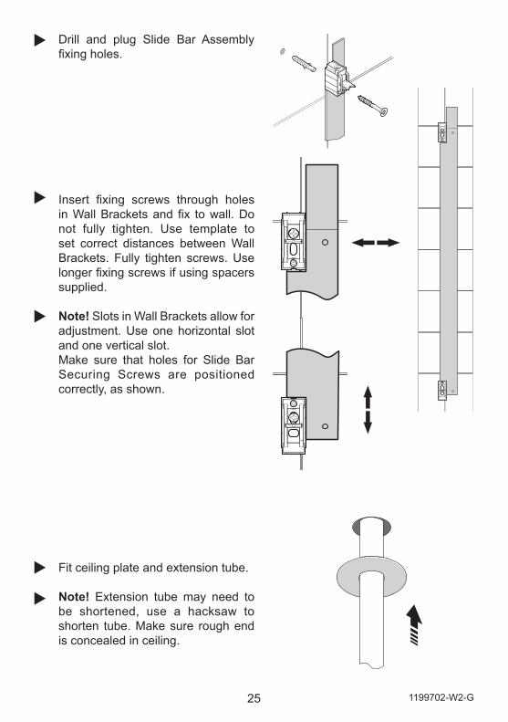
Drill and plug Slide Bar Assembly fixing holes.
Insert fixing screws through holes in Wall Brackets and fix to wall. Do not fully tighten. Use template to set correct distances between Wall Brackets. Fully tighten screws. Use longer fixing screws if using spacers supplied.
Note! Slots in Wall Brackets allow for adjustment. Use one horizontal slot and one vertical slot.Make sure that holes for Slide Bar Securing Screws are positioned correctly, as shown.
Fit ceiling plate and extension tube.
Note! Extension tube may need to be shortened, use a hacksaw to shorten tube. Make sure rough end is concealed in ceiling.
261199702-W2-G
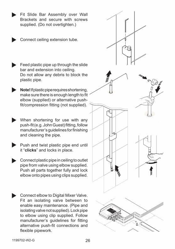
Fit Slide Bar Assembly over Wall Brackets and secure with screws supplied. (Do not overtighten.)
Connect ceiling extension tube.
Feed plastic pipe up through the slide bar and extension into ceiling.Do not allow any debris to block the plastic pipe.
Note! If plastic pipe requires shortening, make sure there is enough length to fit elbow (supplied) or alternative push-fit/compression fitting (not supplied).
When shortening for use with any push-fit (e.g. John Guest) fitting, follow manufacturer’s guidelines for finishing and cleaning the pipe.
Push and twist plastic pipe end until it “clicks” and locks in place.
Connect plastic pipe in ceiling to outlet pipe from valve using elbow supplied. Push all parts together fully and lock elbow onto pipes using clips supplied.
Connect elbow to Digital Mixer Valve. Fit an isolating valve between to enable easy maintenance. (Pipe and isolating valve not supplied). Lock pipe to elbow using clip supplied. Follow manufacturer’s guidelines for fitting alternative push-fit connections and flexible pipework.
27 1199702-W2-G
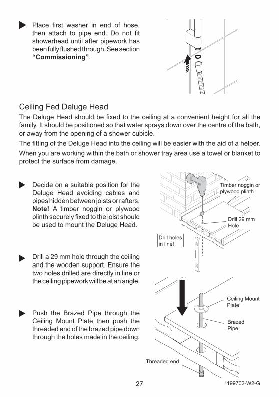
Ceiling Fed Deluge Head The Deluge Head should be fixed to the ceiling at a convenient height for all the family. It should be positioned so that water sprays down over the centre of the bath, or away from the opening of a shower cubicle. The fitting of the Deluge Head into the ceiling will be easier with the aid of a helper.When you are working within the bath or shower tray area use a towel or blanket to protect the surface from damage.
Drill 29 mm Hole
Timber noggin or plywood plinth
Drill holes in line!
Decide on a suitable position for the Deluge Head avoiding cables and pipes hidden between joists or rafters. Note! A timber noggin or plywood plinth securely fixed to the joist should be used to mount the Deluge Head.
Drill a 29 mm hole through the ceiling and the wooden support. Ensure the two holes drilled are directly in line or the ceiling pipework will be at an angle.
Push the Brazed Pipe through the Ceiling Mount Plate then push the threaded end of the brazed pipe down through the holes made in the ceiling.
Ceiling Mount Plate
Brazed Pipe
Threaded end
Place first washer in end of hose, then attach to pipe end. Do not fit showerhead until after pipework has been fully flushed through. See section “Commissioning”.
281199702-W2-G
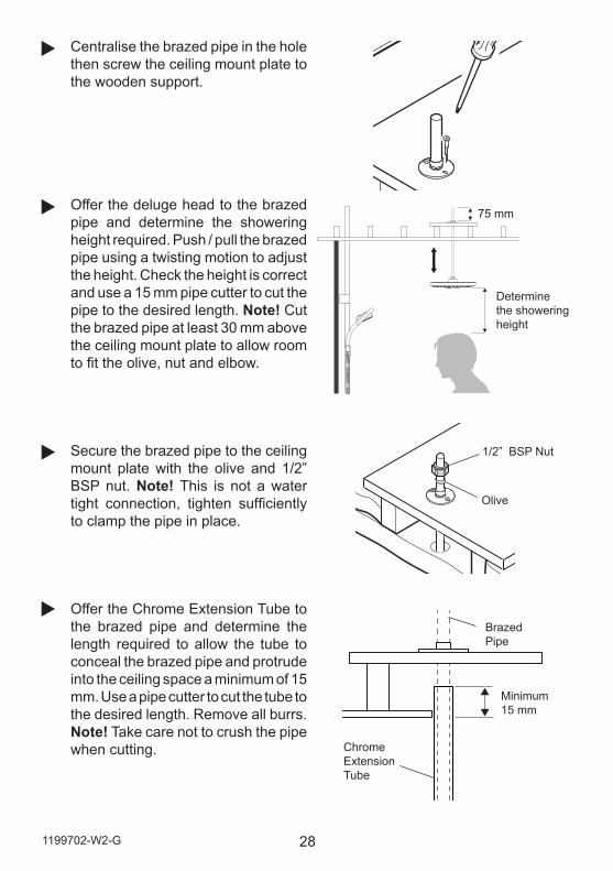
Centralise the brazed pipe in the hole then screw the ceiling mount plate to the wooden support.
Offer the deluge head to the brazed pipe and determine the showering height required. Push / pull the brazed pipe using a twisting motion to adjust the height. Check the height is correct and use a 15 mm pipe cutter to cut the pipe to the desired length. Note! Cut the brazed pipe at least 30 mm above the ceiling mount plate to allow room to fit the olive, nut and elbow.
Secure the brazed pipe to the ceiling mount plate with the olive and 1/2” BSP nut. Note! This is not a water tight connection, tighten sufficiently to clamp the pipe in place.
Offer the Chrome Extension Tube to the brazed pipe and determine the length required to allow the tube to conceal the brazed pipe and protrude into the ceiling space a minimum of 15 mm. Use a pipe cutter to cut the tube to the desired length. Remove all burrs.Note! Take care not to crush the pipe when cutting.
Determine the showering height
75 mm
Brazed Pipe
Chrome Extension Tube
Minimum 15 mm
Olive
1/2” BSP Nut
29 1199702-W2-G
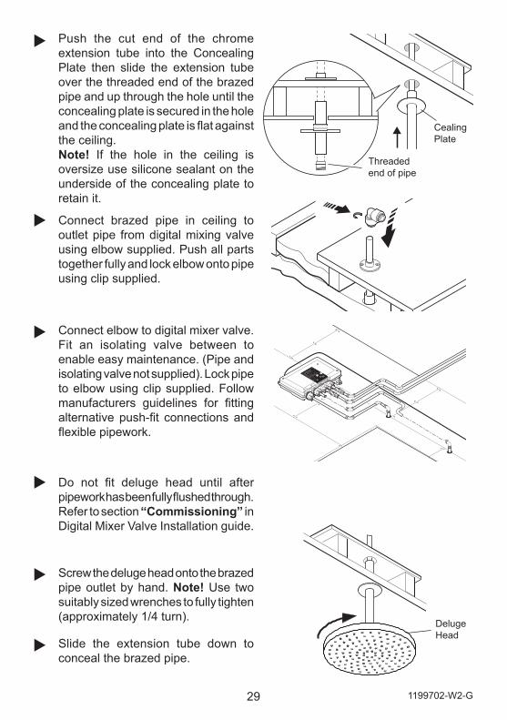
Push the cut end of the chrome extension tube into the Concealing Plate then slide the extension tube over the threaded end of the brazed pipe and up through the hole until the concealing plate is secured in the hole and the concealing plate is flat against the ceiling. Note! If the hole in the ceiling is oversize use silicone sealant on the underside of the concealing plate to retain it.
Screw the deluge head onto the brazed pipe outlet by hand. Note! Use two suitably sized wrenches to fully tighten (approximately 1/4 turn).
Connect elbow to digital mixer valve. Fit an isolating valve between to enable easy maintenance. (Pipe and isolating valve not supplied). Lock pipe to elbow using clip supplied. Follow manufacturers guidelines for fitting alternative push-fit connections and flexible pipework.
Connect brazed pipe in ceiling to outlet pipe from digital mixing valve using elbow supplied. Push all parts together fully and lock elbow onto pipe using clip supplied.
Do not fit deluge head until after pipework has been fully flushed through. Refer to section “Commissioning” in Digital Mixer Valve Installation guide.
Slide the extension tube down to conceal the brazed pipe.
Cealing Plate
Threaded end of pipe
Deluge Head
301199702-W2-G
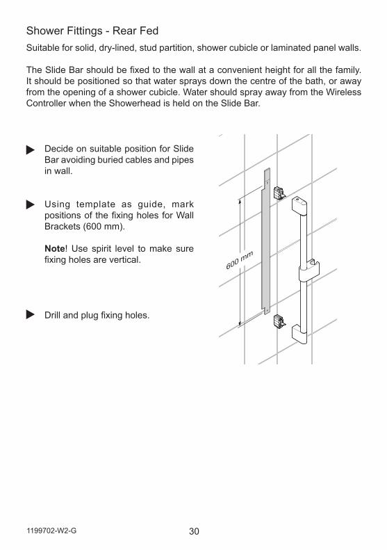
Shower Fittings - Rear Fed
Decide on suitable position for Slide Bar avoiding buried cables and pipes in wall.
Using template as guide, mark positions of the fixing holes for Wall Brackets (600 mm). Note! Use spirit level to make sure fixing holes are vertical.
Drill and plug fixing holes.
600 mm
Suitable for solid, dry-lined, stud partition, shower cubicle or laminated panel walls.
The Slide Bar should be fixed to the wall at a convenient height for all the family. It should be positioned so that water sprays down the centre of the bath, or away from the opening of a shower cubicle. Water should spray away from the Wireless Controller when the Showerhead is held on the Slide Bar.
31 1199702-W2-G
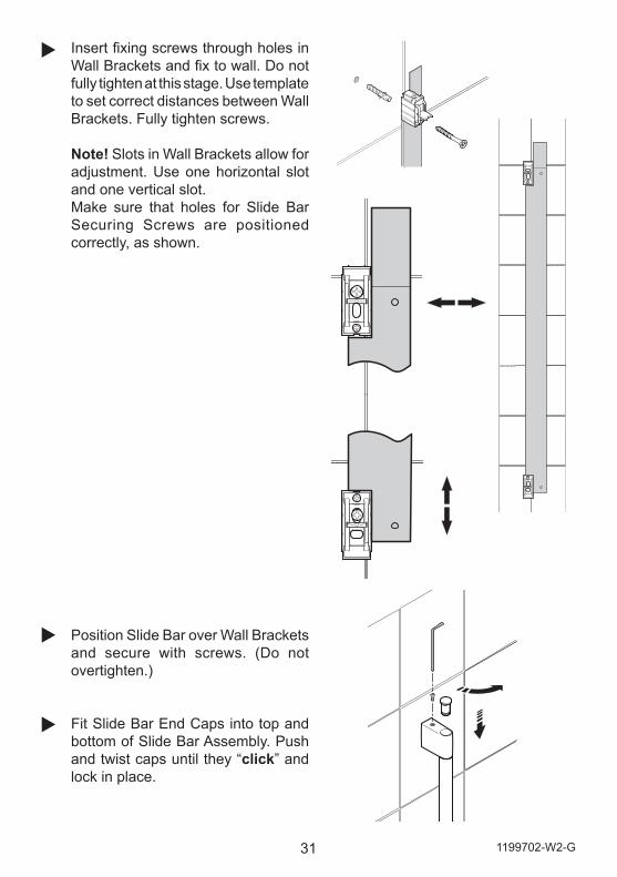
Insert fixing screws through holes in Wall Brackets and fix to wall. Do not fully tighten at this stage. Use template to set correct distances between Wall Brackets. Fully tighten screws.
Note! Slots in Wall Brackets allow for adjustment. Use one horizontal slot and one vertical slot.Make sure that holes for Slide Bar Securing Screws are positioned correctly, as shown.
Position Slide Bar over Wall Brackets and secure with screws. (Do not overtighten.)
Fit Slide Bar End Caps into top and bottom of Slide Bar Assembly. Push and twist caps until they “click” and lock in place.
321199702-W2-G
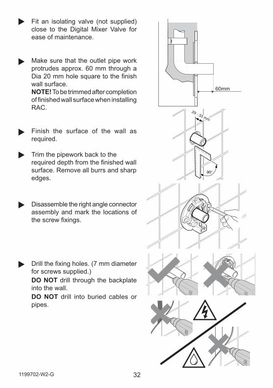
60mm
Fit an isolating valve (not supplied) close to the Digital Mixer Valve for ease of maintenance.
Make sure that the outlet pipe work protrudes approx. 60 mm through a Dia 20 mm hole square to the finish wall surface. NOTE! To be trimmed after completion of finished wall surface when installing RAC.
Finish the surface of the wall as required.
Trim the pipework back to the required depth from the finished wall surface. Remove all burrs and sharp edges.
Disassemble the right angle connector assembly and mark the locations of the screw fixings.
Drill the fixing holes. (7 mm diameter for screws supplied.) DO NOT drill through the backplate into the wall.DO NOT drill into buried cables or pipes.
29 - 33 mm
90°
33 1199702-W2-G
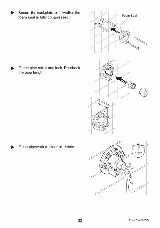
Secure the backplate to the wall so the foam seal is fully compressed.
Fit the pipe collar and lock. Re-check the pipe length.
Flush pipework to clear all debris.
Foam Seal
29 - 33 mm
1 min
341199702-W2-G
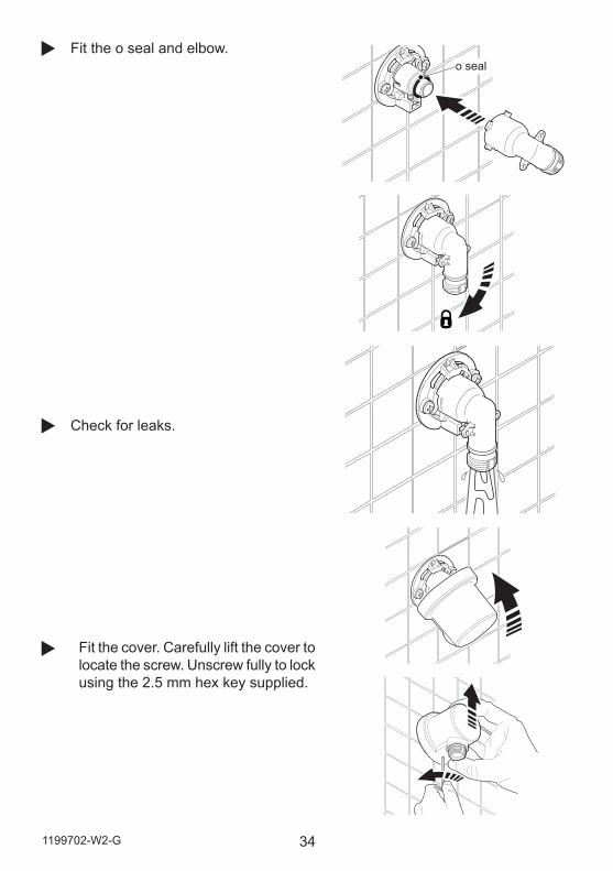
Fit the o seal and elbow.
Check for leaks.
Fit the cover. Carefully lift the cover to locate the screw. Unscrew fully to lock using the 2.5 mm hex key supplied.
o seal
35 1199702-W2-G
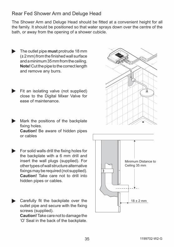
Rear Fed Shower Arm and Deluge HeadThe Shower Arm and Deluge Head should be fitted at a convenient height for all the family. It should be positioned so that water sprays down over the centre of the bath, or away from the opening of a shower cubicle.
The outlet pipe must protrude 18 mm (± 2 mm) from the finished wall surface and a minimum 35 mm from the ceiling.Note! Cut the pipe to the correct length and remove any burrs.
Fit an isolating valve (not supplied) close to the Digital Mixer Valve for ease of maintenance.
Mark the positions of the backplate fixing holes. Caution! Be aware of hidden pipes or cables
For solid walls drill the fixing holes for the backplate with a 6 mm drill and insert the wall plugs (supplied). For other types of wall structure alternative fixings may be required (not supplied). Caution! Take care not to drill into hidden pipes or cables.
Carefully fit the backplate over the outlet pipe and secure with the fixing screws (supplied). Caution! Take care not to damage the ‘O’ Seal in the back of the backplate.
18 ± 2 mm
Minimum Distance to Ceiling 35 mm
361199702-W2-G
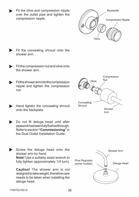
Olive
Compression Nipple
Fit the olive and compression nipple over the outlet pipe and tighten the compression nipple.
Fit the concealing shroud onto the shower arm.
Fit the compression nut and olive onto the shower arm.
Fit the shower arm into the compression nipple and tighten the compression nut.
Hand tighten the concealing shroud onto the backplate.
Do not fit deluge head until after pipework has been fully flushed through. Refer to section “Commissioning” in the Dual Outlet Installation Guide.
Screw the deluge head onto the shower arm by hand.Note! Use a suitably sized wrench to fully tighten (approximately 1/4 turn).
Caution! The shower arm is not designed to take weight, therefore care needs to be taken when installing the deluge head.
Concealing Shroud
Compression NutOlive
Shower Arm
Shower Arm
Deluge HeadFlow Regulator (some models)
Backplate
37 1199702-W2-G
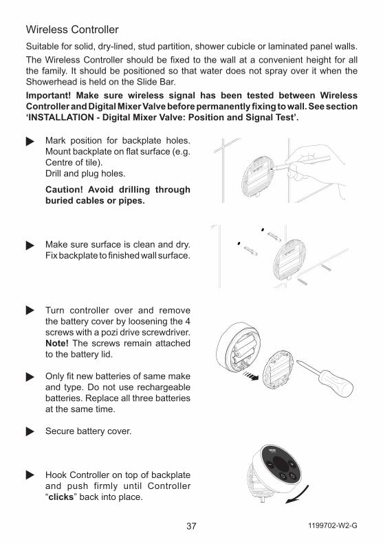
Mark position for backplate holes. Mount backplate on flat surface (e.g. Centre of tile).Drill and plug holes.
Caution! Avoid drilling through buried cables or pipes.
Make sure surface is clean and dry. Fix backplate to finished wall surface.
Turn controller over and remove the battery cover by loosening the 4 screws with a pozi drive screwdriver.Note! The screws remain attached to the battery lid.
Only fit new batteries of same make and type. Do not use rechargeable batteries. Replace all three batteries at the same time.
Secure battery cover.
Hook Controller on top of backplate and push firmly until Controller “clicks” back into place.
Wireless Controller Suitable for solid, dry-lined, stud partition, shower cubicle or laminated panel walls.The Wireless Controller should be fixed to the wall at a convenient height for all the family. It should be positioned so that water does not spray over it when the Showerhead is held on the Slide Bar.Important! Make sure wireless signal has been tested between Wireless Controller and Digital Mixer Valve before permanently fixing to wall. See section ‘INSTALLATION - Digital Mixer Valve: Position and Signal Test’.
381199702-W2-G
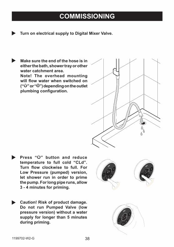
Press “ 1 2” button and reduce temperature to full cold “CLd”. Turn flow clockwise to full. For Low Pressure (pumped) version, let shower run in order to prime the pump. For long pipe runs, allow 3 - 4 minutes for priming.
Caution! Risk of product damage. Do not run Pumped Valve (low pressure version) without a water supply for longer than 5 minutes during priming.
COMMISSIONING
Make sure the end of the hose is in either the bath, shower tray or other water catchment area.Note! The overhead mounting will flow water when switched on (“ 1 2” or “ 2 ”) depending on the outlet plumbing configuration.
Turn on electrical supply to Digital Mixer Valve.
39 1199702-W2-G
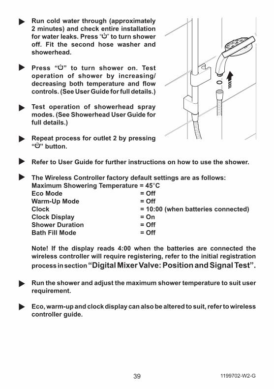
Run cold water through (approximately 2 minutes) and check entire installation for water leaks. Press “ 1 ” to turn shower off. Fit the second hose washer and showerhead.
Press “ 1 ” to turn shower on. Test operation of shower by increasing/decreasing both temperature and flow controls. (See User Guide for full details.)
Test operation of showerhead spray modes. (See Showerhead User Guide for full details.)
Repeat process for outlet 2 by pressing “ 2 ” button.
Refer to User Guide for further instructions on how to use the shower.
The Wireless Controller factory default settings are as follows:Maximum Showering Temperature = 45°CEco Mode = OffWarm-Up Mode = OffClock = 10:00 (when batteries connected)Clock Display = OnShower Duration = OffBath Fill Mode = Off
Note! If the display reads 4:00 when the batteries are connected the wireless controller will require registering, refer to the initial registration process in section “Digital Mixer Valve: Position and Signal Test”. Run the shower and adjust the maximum shower temperature to suit user requirement.
Eco, warm-up and clock display can also be altered to suit, refer to wireless controller guide.
401199702-W2-G
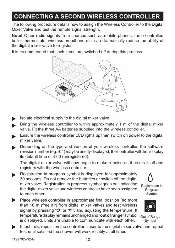
CONNECTING A SECOND WIRELESS CONTROLLERThe following procedure details how to assign the Wireless Controller to the Digital Mixer Valve and test the remote signal strength.Note! Other radio signals from sources such as mobile phones, radio controlled boiler thermostats, wireless broadband etc. can dramatically reduce the ability of the digital mixer valve to register.It is recommended that such items are switched off during this process.
Isolate electrical supply to the digital mixer valve. Bring the wireless controller to within approximately 1 m of the digital mixer valve. Fit the three AA batteries supplied into the wireless controller. Ensure the wireless controller LCD lights up then switch on power to the digital mixer valve.Depending on the type and version of your wireless controller, the software revision number (eg. r04) may be briefly displayed, the controller will then display its default time of 4:00 (unregistered).The digital mixer valve will now begin to make a noise as it resets itself and registers with the wireless controller.Registration in progress symbol is displayed for approximately 30 seconds. Do not remove the batteries or switch off the digital mixer valve. Registration in progress symbol goes out indicating the digital mixer valve and wireless controller have been assigned to each other.Place wireless controller in approximate final position (no more than 10 m (free air) from digital mixer valve) and test wireless signal by pressing “ 1 ” or “ 2 ”, and adjusting the temperature. If temperature display remains unchanged and “out of range” symbol is displayed, units are unable to communicate with each other.If test fails, reposition the controller closer to the digital mixer valve and repeat test until satisfied the shower will work reliably at all times.
Out of Range Symbol
Registration in ProgressSymbol
41 1199702-W2-G
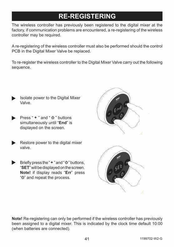
Isolate power to the Digital Mixer Valve.
Press “ + ” and “ ” buttons simultaneously until “End” is displayed on the screen.
Restore power to the digital mixer valve.
Briefly press the “ + ” and “ ” buttons, “SET” will be displayed on the screen. Note! if display reads “Err” press “ ” and repeat the process.
Note! Re-registering can only be performed if the wireless controller has previously been assigned to a digital mixer. This is indicated by the clock time default 10:00 (when batteries are connected).
RE-REGISTERINGThe wireless controller has previously been registered to the digital mixer at the factory, if communication problems are encountered, a re-registering of the wireless controller may be required.
A re-registering of the wireless controller must also be performed should the control PCB in the Digital Mixer Valve be replaced.
To re-register the wireless controller to the Digital Mixer Valve carry out the following sequence.
421199702-W2-G
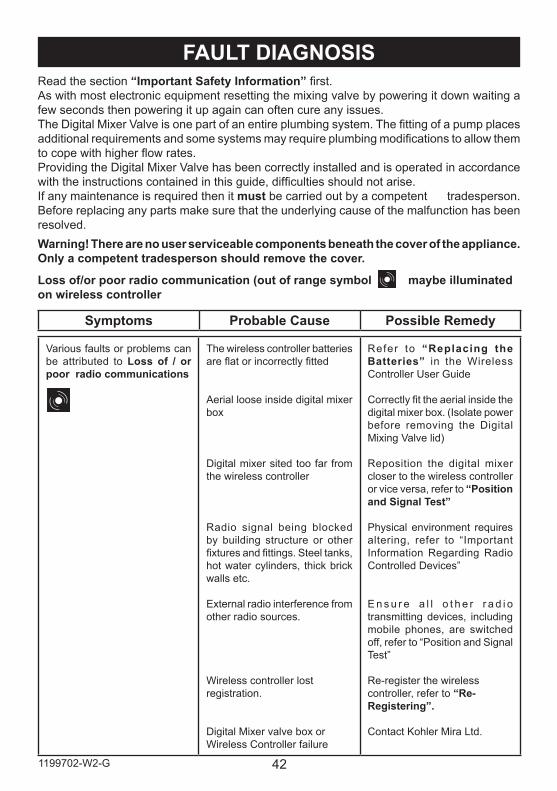
FAULT DIAGNOSISRead the section “Important Safety Information” first.As with most electronic equipment resetting the mixing valve by powering it down waiting a few seconds then powering it up again can often cure any issues.The Digital Mixer Valve is one part of an entire plumbing system. The fitting of a pump places additional requirements and some systems may require plumbing modifications to allow them to cope with higher flow rates.Providing the Digital Mixer Valve has been correctly installed and is operated in accordance with the instructions contained in this guide, difficulties should not arise.If any maintenance is required then it must be carried out by a competent tradesperson. Before replacing any parts make sure that the underlying cause of the malfunction has been resolved.Warning! There are no user serviceable components beneath the cover of the appliance. Only a competent tradesperson should remove the cover.
Various faults or problems can be attributed to Loss of / or poor radio communications
The wireless controller batteries are flat or incorrectly fitted
Aerial loose inside digital mixer box
Digital mixer sited too far from the wireless controller
Radio signal being blocked by building structure or other fixtures and fittings. Steel tanks, hot water cylinders, thick brick walls etc.
External radio interference from other radio sources.
Wireless controller lost registration.
Digital Mixer valve box or Wireless Controller failure
Refer to “Replacing the Batteries” in the Wireless Controller User Guide
Correctly fit the aerial inside the digital mixer box. (Isolate power before removing the Digital Mixing Valve lid)
Reposition the digital mixer closer to the wireless controller or vice versa, refer to “Position and Signal Test”
Physical environment requires altering, refer to “Important Information Regarding Radio Controlled Devices”
E n s u r e a l l o t h e r r a d i o transmitting devices, including mobile phones, are switched off, refer to “Position and Signal Test”
Re-register the wireless controller, refer to “Re-Registering”.
Contact Kohler Mira Ltd.
Symptoms Probable Cause Possible Remedy
Loss of/or poor radio communication (out of range symbol maybe illuminated on wireless controller
43 1199702-W2-G
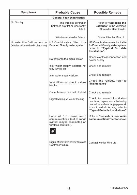
Symptoms Probable Cause Possible RemedyGeneral Fault Diagnostics
No Display The wireless controller batteries are flat or incorrectly
fitted.
Wireless controller failure.
Refer to “Replacing the Batteries” in the Wireless
Controller User Guide.
Contact Kohler Mira Ltd.
No water flow / will not turn on (wireless controller display is on)
HP/Combi valve fitted to a Pumped Gravity water system
No power to the digital mixer
Inlet water supply isolators not fully turned on
Inlet water supply failure
Inlet filters or check valves blocked
Outlet hose or handset blocked
Digital Mixing valve air locking
Loss o f / o r poo r r ad io communications (out of range symbol maybe illuminated on wireless controller).
Digital Mixer valve box or Wireless Controller failure
HP/Combi valves are not suitable for Pumped Gravity water system, refer to “Typical Suitable Installation”.
Check electrical connection and power supply
Check and remedy
Check and remedy
Check and remedy, refer to “Maintenance”
Check and remedy
Check for correct installation practices, repeat commissioning procedure and rearrange pipework to avoid airlock forming, refer to “Typical Suitable Installations”
Refer to “Loss of / or poor radio communications” section above
Contact Kohler Mira Ltd
441199702-W2-G
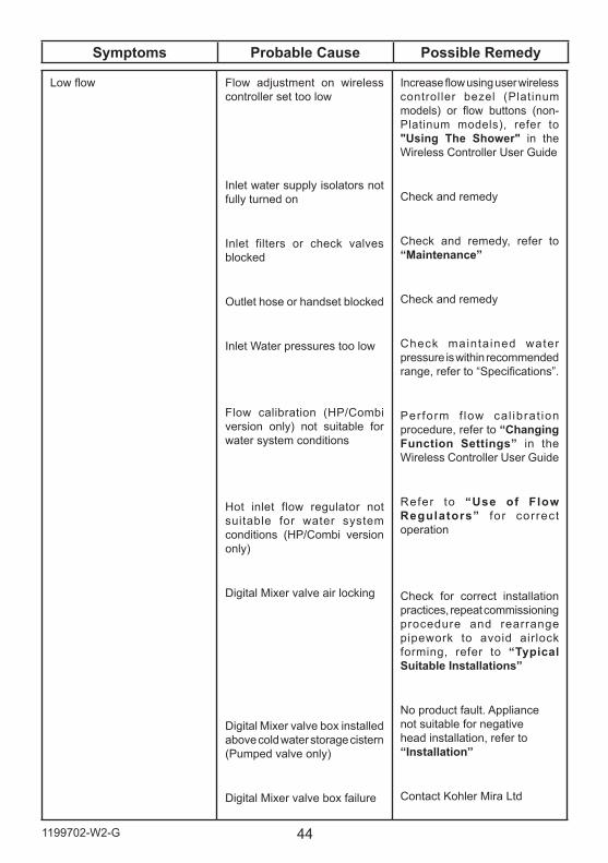
Low flow Flow adjustment on wireless controller set too low
Inlet water supply isolators not fully turned on
Inlet filters or check valves blocked
Outlet hose or handset blocked
Inlet Water pressures too low
Flow calibration (HP/Combi version only) not suitable for water system conditions
Hot inlet flow regulator not suitable for water system conditions (HP/Combi version only)
Digital Mixer valve air locking
Digital Mixer valve box installed above cold water storage cistern (Pumped valve only)
Digital Mixer valve box failure
Increase flow using user wireless controller bezel (Platinum models) or flow buttons (non-Platinum models), refer to "Using The Shower" in the Wireless Controller User Guide
Check and remedy
Check and remedy, refer to “Maintenance”
Check and remedy
Check maintained water pressure is within recommended range, refer to “Specifications”.
Perform f low cal ibrat ion procedure, refer to “Changing Function Settings” in the Wireless Controller User Guide
Refer to “Use of Flow Regulators” for correct operation
Check for correct installation practices, repeat commissioning procedure and rearrange pipework to avoid airlock forming, refer to “Typical Suitable Installations”
No product fault. Appliance not suitable for negative head installation, refer to “Installation”
Contact Kohler Mira Ltd
Symptoms Probable Cause Possible Remedy
45 1199702-W2-G
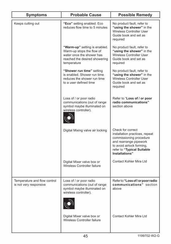
Keeps cutting out “Eco” setting enabled. Eco reduces flow time to 5 minutes
“Warm-up” setting is enabled. Warm-up stops the flow of water once the shower has reached the desired showering temperature
“Shower run time” setting is enabled. Shower run time reduces the shower run time to a user defined time
Loss of / or poor radio communications (out of range symbol maybe illuminated on wireless controller).
Digital Mixing valve air locking
Digital Mixer valve box or Wireless Controller failure
No product fault, refer to “using the shower” in the Wireless Controller User Guide book and set as required
No product fault, refer to “using the shower” in the Wireless Controller User Guide book and set as required
No product fault, refer to “using the shower” in the Wireless Controller User Guide book and set as required
Refer to “Loss of / or poor radio communications” section above
Check for correct installation practices, repeat commissioning procedure and rearrange pipework to avoid airlock forming, refer to “Typical Suitable Installations”
Contact Kohler Mira Ltd
Temperature and flow control is not very responsive
Loss of / or poor radio communications (out of range symbol maybe illuminated on wireless controller).
Digital Mixer valve box or Wireless Controller failure
Refer to “Loss of / or poor radio communications” section above
Contact Kohler Mira Ltd
Symptoms Probable Cause Possible Remedy
461199702-W2-G
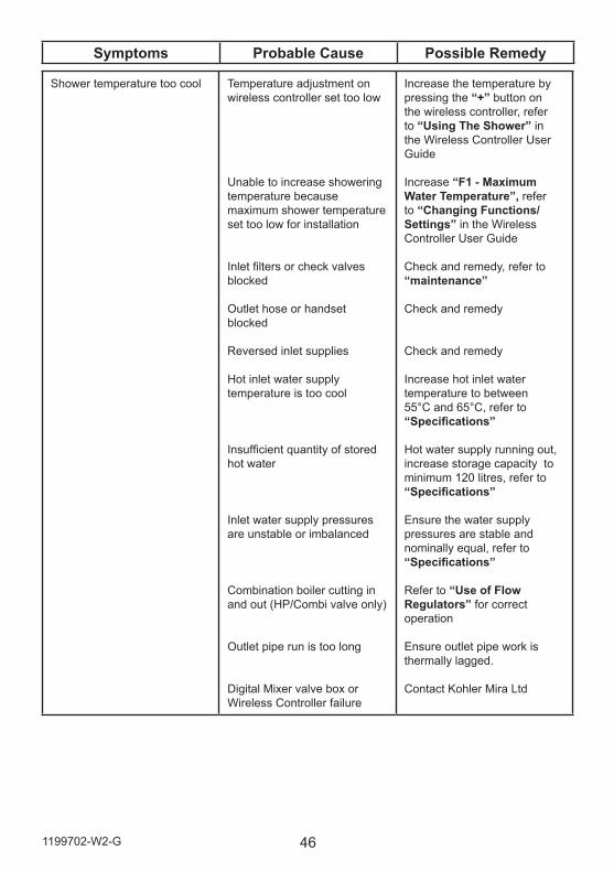
Shower temperature too cool Temperature adjustment on wireless controller set too low
Unable to increase showering temperature because maximum shower temperature set too low for installation
Inlet filters or check valves blocked
Outlet hose or handset blocked
Reversed inlet supplies
Hot inlet water supply temperature is too cool
Insufficient quantity of stored hot water
Inlet water supply pressures are unstable or imbalanced
Combination boiler cutting in and out (HP/Combi valve only)
Outlet pipe run is too long
Digital Mixer valve box or Wireless Controller failure
Increase the temperature by pressing the “+” button on the wireless controller, refer to “Using The Shower” in the Wireless Controller User Guide
Increase “F1 - Maximum Water Temperature”, refer to “Changing Functions/ Settings” in the Wireless Controller User Guide
Check and remedy, refer to “maintenance”
Check and remedy
Check and remedy
Increase hot inlet water temperature to between 55°C and 65°C, refer to “Specifications”
Hot water supply running out, increase storage capacity to minimum 120 litres, refer to “Specifications”
Ensure the water supply pressures are stable and nominally equal, refer to “Specifications”
Refer to “Use of Flow Regulators” for correct operation
Ensure outlet pipe work is thermally lagged.
Contact Kohler Mira Ltd
Symptoms Probable Cause Possible Remedy
47 1199702-W2-G
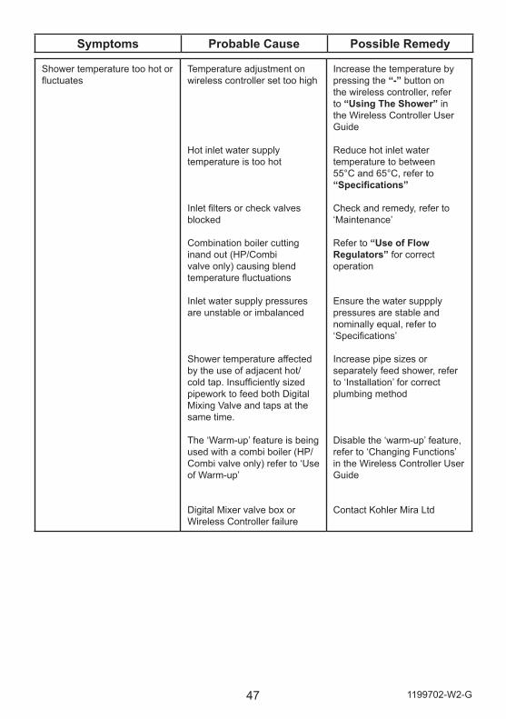
Shower temperature too hot or fluctuates
Temperature adjustment on wireless controller set too high
Hot inlet water supply temperature is too hot
Inlet filters or check valves blocked
Combination boiler cutting inand out (HP/Combi valve only) causing blend temperature fluctuations
Inlet water supply pressures are unstable or imbalanced
Shower temperature affected by the use of adjacent hot/cold tap. Insufficiently sized pipework to feed both Digital Mixing Valve and taps at the same time.
The ‘Warm-up’ feature is being used with a combi boiler (HP/Combi valve only) refer to ‘Use of Warm-up’
Digital Mixer valve box or Wireless Controller failure
Increase the temperature by pressing the “-” button on the wireless controller, refer to “Using The Shower” in the Wireless Controller User Guide
Reduce hot inlet water temperature to between 55°C and 65°C, refer to “Specifications”
Check and remedy, refer to ‘Maintenance’
Refer to “Use of Flow Regulators” for correct operation
Ensure the water suppply pressures are stable and nominally equal, refer to ‘Specifications’
Increase pipe sizes or separately feed shower, refer to ‘Installation’ for correct plumbing method
Disable the ‘warm-up’ feature, refer to ‘Changing Functions’ in the Wireless Controller User Guide
Contact Kohler Mira Ltd
Symptoms Probable Cause Possible Remedy
481199702-W2-G
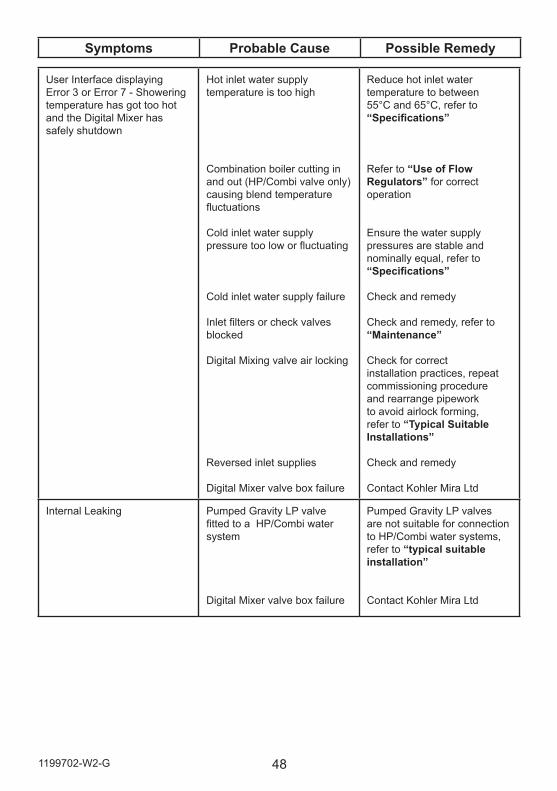
User Interface displaying Error 3 or Error 7 - Showering temperature has got too hot and the Digital Mixer has safely shutdown
Hot inlet water supply temperature is too high
Combination boiler cutting in and out (HP/Combi valve only) causing blend temperature fluctuations
Cold inlet water supply pressure too low or fluctuating
Cold inlet water supply failure
Inlet filters or check valves blocked
Digital Mixing valve air locking
Reversed inlet supplies
Digital Mixer valve box failure
Reduce hot inlet water temperature to between 55°C and 65°C, refer to “Specifications”
Refer to “Use of Flow Regulators” for correct operation
Ensure the water supply pressures are stable and nominally equal, refer to “Specifications”
Check and remedy
Check and remedy, refer to “Maintenance”
Check for correct installation practices, repeat commissioning procedure and rearrange pipework to avoid airlock forming, refer to “Typical Suitable Installations”
Check and remedy
Contact Kohler Mira Ltd
Internal Leaking Pumped Gravity LP valve fitted to a HP/Combi water system
Digital Mixer valve box failure
Pumped Gravity LP valves are not suitable for connection to HP/Combi water systems, refer to “typical suitable installation”
Contact Kohler Mira Ltd
Symptoms Probable Cause Possible Remedy
49 1199702-W2-G
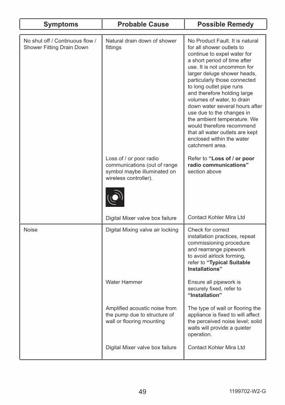
No shut off / Continuous flow / Shower Fitting Drain Down
Natural drain down of shower fittings
Loss of / or poor radio communications (out of range symbol maybe illuminated on wireless controller).
Digital Mixer valve box failure
No Product Fault. It is natural for all shower outlets to continue to expel water for a short period of time after use. It is not uncommon for larger deluge shower heads, particularly those connected to long outlet pipe runs and therefore holding large volumes of water, to drain down water several hours after use due to the changes in the ambient temperature. We would therefore recommend that all water outlets are kept enclosed within the water catchment area.
Refer to “Loss of / or poor radio communications” section above
Contact Kohler Mira Ltd
Noise Digital Mixing valve air locking
Water Hammer
Amplified acoustic noise from the pump due to structure of wall or flooring mounting
Digital Mixer valve box failure
Check for correct installation practices, repeat commissioning procedure and rearrange pipework to avoid airlock forming, refer to “Typical Suitable Installations”
Ensure all pipework is securely fixed, refer to “Installation”
The type of wall or flooring the appliance is fixed to will affect the perceived noise level; solid walls will provide a quieter operation.
Contact Kohler Mira Ltd
Symptoms Probable Cause Possible Remedy
501199702-W2-G
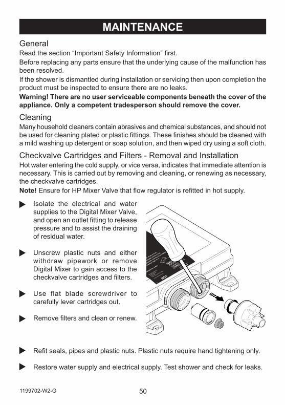
Isolate the electrical and water supplies to the Digital Mixer Valve, and open an outlet fitting to release pressure and to assist the draining of residual water.
Unscrew plastic nuts and either withdraw pipework or remove Digital Mixer to gain access to the checkvalve cartridges and filters.
Use flat blade screwdriver to carefully lever cartridges out.
Remove filters and clean or renew.
Refit seals, pipes and plastic nuts. Plastic nuts require hand tightening only.
Restore water supply and electrical supply. Test shower and check for leaks.
MAINTENANCEGeneralRead the section “Important Safety Information” first.Before replacing any parts ensure that the underlying cause of the malfunction has been resolved.If the shower is dismantled during installation or servicing then upon completion the product must be inspected to ensure there are no leaks.Warning! There are no user serviceable components beneath the cover of the appliance. Only a competent tradesperson should remove the cover.
CleaningMany household cleaners contain abrasives and chemical substances, and should not be used for cleaning plated or plastic fittings. These finishes should be cleaned with a mild washing up detergent or soap solution, and then wiped dry using a soft cloth.
Checkvalve Cartridges and Filters - Removal and InstallationHot water entering the cold supply, or vice versa, indicates that immediate attention is necessary. This is carried out by removing and cleaning, or renewing as necessary, the checkvalve cartridges.Note! Ensure for HP Mixer Valve that flow regulator is refitted in hot supply.
51 1199702-W2-G
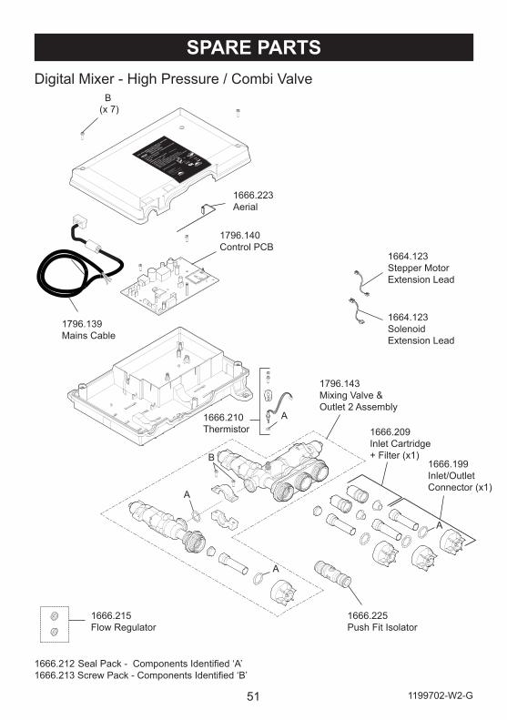
SPARE PARTS
1666.212 Seal Pack - Components Identified ‘A’1666.213 Screw Pack - Components Identified ‘B’
1796.140Control PCB
1666.223Aerial
1666.199Inlet/Outlet Connector (x1)
1666.209Inlet Cartridge+ Filter (x1)
1666.225Push Fit Isolator
1666.210Thermistor
1796.143Mixing Valve & Outlet 2 Assembly
1796.139Mains Cable
A
A
B
B(x 7)
A
Digital Mixer - High Pressure / Combi Valve
A
1664.123Stepper Motor Extension Lead
1664.123Solenoid Extension Lead
1666.215 Flow Regulator
521199702-W2-G
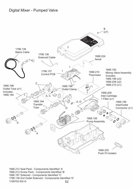
1666.212 Seal Pack - Components Identified ‘A’1666.213 Screw Pack - Components Identified ‘B’1666.197 Solenoid - Components Identified ‘C’1796.138 2nd Outlet Solenoid - Components Identified ‘D’
Digital Mixer - Pumped Valve
1666.199Inlet/Outlet Connector (x1)
1666.209Inlet Cartridge+ Filter (x1)
1666.195Pump Assembly
1666.192Mixing Valve AssemblyIncludes:1666.199 (x3)1666.209 (x2)1666.210 (x1)
1666.210Thermistor
1666.224Aerial
1666.194Transfer Tube
1666.198Outlet Tube (x1)Includes:1666.194
1666.196Outlet Clamp
1796.136Solenoid Cable
1796.137Control PCB
1796.139Mains Cable
1666.225Push Fit Isolator
B (x7)
C
A
A
D
A, C
A, D
53 1199702-W2-G
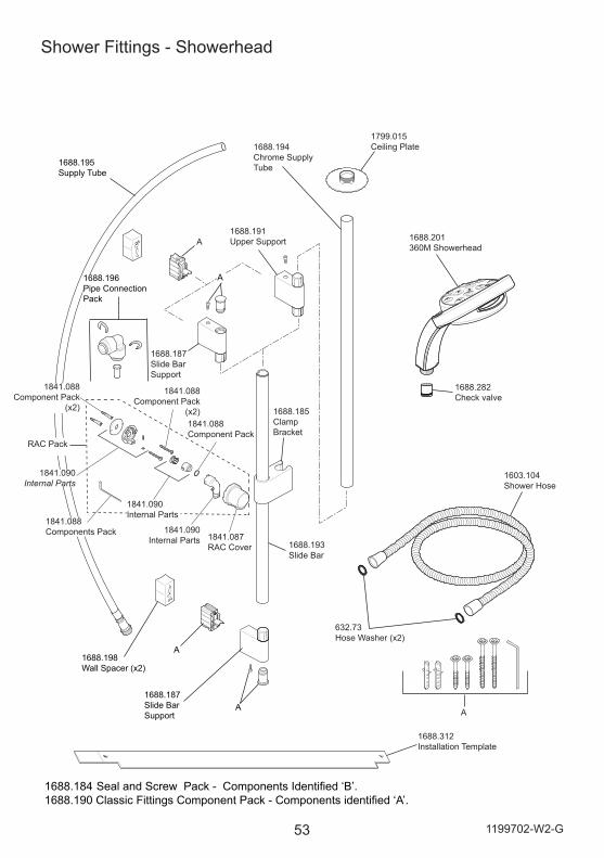
Shower Fittings - Showerhead
1603.104Shower Hose
1688.187Slide Bar Support
1688.187Slide Bar Support
1688.196Pipe ConnectionPack
1688.198Wall Spacer (x2)
1688.191Upper Support
1799.015Ceiling Plate
1688.195Supply Tube
632.73Hose Washer (x2)
1688.312Installation Template
1688.185Clamp Bracket
1688.193Slide Bar
1688.201360M Showerhead
A
A
A
A
1688.184 Seal and Screw Pack - Components Identified ‘B’.1688.190 Classic Fittings Component Pack - Components identified ‘A’.
A
1688.194Chrome Supply Tube
1841.090 Internal Parts
1841.088 Components Pack
1841.088 Component Pack
1841.090 Internal Parts
1841.088 Component Pack
(x2)
1841.087 RAC Cover
1688.282Check valve
RAC Pack
1841.088 Component Pack
(x2)
1841.090 Internal Parts
541199702-W2-G
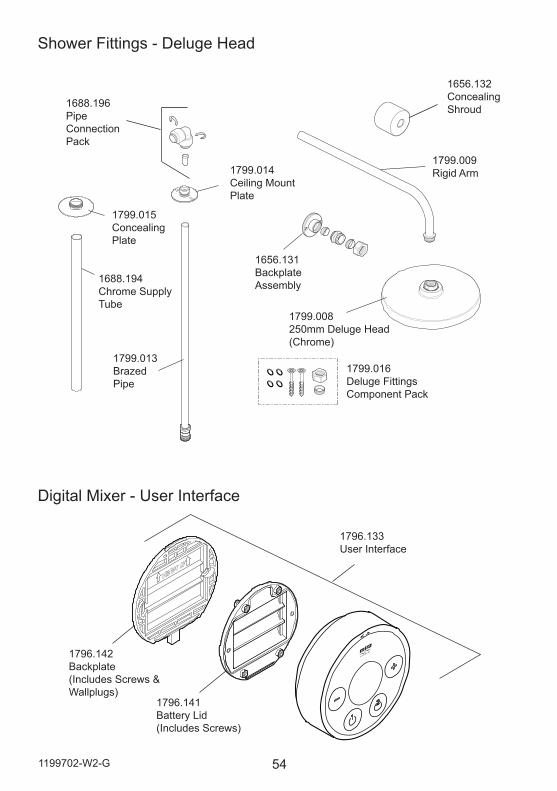
Shower Fittings - Deluge Head
1799.009Rigid Arm
1688.196Pipe Connection Pack
1799.014Ceiling Mount Plate
1799.015Concealing Plate
1799.013Brazed Pipe
1656.131Backplate Assembly
1799.008250mm Deluge Head (Chrome)
1799.016Deluge Fittings Component Pack
1688.194Chrome Supply Tube
Digital Mixer - User Interface
1796.133User Interface
1796.142Backplate (Includes Screws & Wallplugs)
1796.141Battery Lid (Includes Screws)
1656.132Concealing Shroud
55 1199702-W2-G
DISPOSAL AND RECYCLINGEnd of Product Life
Electrical and electronic devices contain a range of materials that can be separated for recycling and used in new products.
This product should not be disposed of with your general household waste. When this product has reached the end of its serviceable life, please remove the batteries and take it to a recognised WEEE (Waste Electrical and Electronic Equipment) collection facility such as your local civic amenity site for recycling.
Your local authority or retailer will be able to advise you of your nearest collection facility.
Batteries
Spent batteries should not be disposed of with your normal household waste. Contact your local authority for information on waste disposal and recycling.
561199702-W2-G (L15F, N85K, N85L, N86F) (1796) © Kohler Mira Limited, May 2017
CUSTOMER SERVICE
Mira is a registered trade mark of Kohler Mira Limited.
The company reserves the right to alter
14648
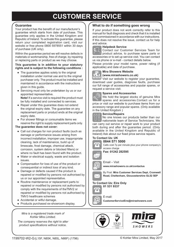
Guarantee
guarantee which starts from date of purchase. This guarantee only applies in the United Kingdom and Republic of Ireland. To activate this guarantee, please return your completed registration card, visit our website or free phone 0800 5978551 within 30 days of purchase (UK only).Within the guarantee period we will resolve defects in materials or workmanship, free of charge, by repairing or replacing parts or product as we may choose.This guarantee is in addition to your statutory rights and is subject to the following conditions : ● The guarantee applies solely to the original installation under normal use and to the original purchaser only. The product must be installed and maintained in accordance with the instructions given in this guide. ● Servicing must only be undertaken by us or our appointed representative. Note! If a service visit is required the product must be fully installed and connected to services. ● Repair under this guarantee does not extend the original expiry date. The guarantee on any replacement parts or product ends at the original expiry date. ● reserve the right to supply replacement parts only.The guarantee does not cover: ● Call out charges for non product faults (such as damage or performance issues arising from incorrect installation, improper use, inappropriate cleaning, lack of maintenance, build up of limescale, frost damage, chemical attack,
where no fault has been found with the product. ● Water or electrical supply, waste and isolation issues. ● Compensation for loss of use of the product or consequential or indirect loss of any kind. ● Damage or defects caused if the product is us or our appointed representative. ● ● Accidental or wilful damage. ● Products purchased ex-showroom display.
What to do if something goes wrongIf your product does not work correctly refer to this manual for fault diagnosis and check that it is installed and commissioned in accordance with our instructions.If this does not resolve the issue, contact us for help and advice.
Helpdesk ServiceContact our Customer Services Team for product advice, to purchase spare parts or
accessories or to set up service visit. You can contact us via phone or e-mail - contact details below.Please provide your model name, power rating (if applicable) and date of purchase.
Mira Showers Website (www.mirashowers.co.uk)Visit our website to register your guarantee,
download user guides, diagnose faults, purchase our full range of accessories and popular spares, or request a service visit.
Spares and AccessoriesWe hold the largest stocks of genuine Mira spares and accessories.Contact us for a
price or visit our website to purchase items from our accessory range and popular spares. (Only available in the United Kingdom )
Service/RepairsNo one knows our products better than our nationwide team of Service Technicians. We
can carry out service or repair work to your product both during and after the guarantee period. (Only available in the United Kingdom and Republic of
0844 571 5000
Fax: 01242 282595
Email – Visit www.mirashowers.co.uk/contactus
By Post: Mira Customer Services Dept, Cromwell Road, Cheltenham, Gloucestershire GL52 5EP
To Contact Us: Eire Only01 531 9337
E-mail: [email protected]
To Contact Us: UK
Calls cost 7p per minute plus your phone company’s access charge
Your product has the benefit of our manufacturer’s
For shower fittings or consumable items we
corrosion, system debris or blocked filters) or
repaired or modified by persons not authorised by
TMV3 healthcare schemes
Routine maintenance or replacement parts torepaired or modified by persons not authorised bycomply with the requirements of theTMV2 orrepaired or modified by persons not authorised by
product specifications without notice.
Ireland) Ask about our fixed price service repairs.
CUSTOMER SERVICE


