84
1 These instructions must be left with the user Installation Guide Mira Platinum Dual

1
These instructions must be left with the user
Installation Guide
Mira Platinum Dual

2
������������ ���� ���������������������� ��������� ����������� of your new shower, then please refer to the Fault Diagnosis section,
before contacting Kohler Mira Ltd.Our telephone and fax numbers can be found in the back of this guide.
CONTENTSIntroduction................................................................................................3
Products Covered by this Guide...........................................................3Guarantee ............................................................................................3Patents and Design Registration..........................................................3
Important Safety Information .....................................................................4Pack Contents ...........................................................................................6���������� � ............................................................................................9
Standards and Approvals .....................................................................9Dimensions.............................................................................................. 11Installation ...............................................................................................13
General...............................................................................................13Important Information Regarding Radio Controlled Devices..............13Use of Flow Regulators with Combination Boilers ............................15Installation Schematic ........................................................................19Digital Mixer Valve: Position and Signal Test .....................................21Shower Fittings - Ceiling Fed Slide Bar / Showerhead ......................25
Ceiling Fed Deluge Head ......................................28Rear Fed Slide Bar / Showerhead..........................31Rear Fed Shower Arm and Deluge Head...............35
Wireless Controller .............................................................................37Commissioning........................................................................................38Re-Registering ........................................................................................40Fault Diagnosis........................................................................................41Maintenance............................................................................................45Spare Parts .............................................................................................46Accessories .............................................................................................50Disposal and Recycling ...........................................................................51Customer Service....................................................................................52

3
Thank you for purchasing a quality Mira product. To enjoy the full potential of your new product, please take time to read this guide thoroughly. Having done so, keep it handy for future reference.The Mira Platinum Dual Outlet Mixer Valve is designed to be used with the Mira ����� ��������������� ������ ���
Products Covered by this GuideMira Platinum Dual Digital Mixer - High Pressure / Combi ValveMira Platinum Dual Digital Mixer - Pumped Valve.Mira Platinum Dual Wireless Controller.Mira 360 Fittings (Ceiling Fed or Rear Fed).
GuaranteeFor domestic installations, Mira Showers guarantee the Mira Platinum Dual against � ���������� �������������������� ������������������������������������������������������������������ �������� ��������For non-domestic installations. Mira Showers guarantee the Mira Platinum Dual against any defect in materials or workmanship for a period of one year from the date of purchase.For terms and conditions refer to the back cover of this guide.
Patents and Design RegistrationDesign Registration 001065023-0003Patents GB: 2 392 225, 2 421 297
USA: 7 240 850Patent Applications UK: 0723827.2
0715612.80804172.5
Euro: 03254070.0USA: US-2007-0221740-A1PCT/GB2008/004020WO 2009/022112
INTRODUCTION
Recommended Usage
Domestic �Light Commercial �Heavy Commercial �Healthcare �

4
IMPORTANT SAFETY INFORMATIONWarning!Follow all warnings, cautions and instructions contained in this guide, and on or inside the appliance.
1. THIS APPLIANCE MUST BE EARTHED. ENSURE SUPPLEMENTARY BONDING COMPLIES WITH THE “REQUIREMENTS FOR ELECTRICAL INSTALLATIONS”. The Mira Digital Mixer Valve is intended to be permanently �� �������������������������������� ������������ ����������!���� ������������������������� ������������ ���������"����������� ������������� ��� �������� ��������local wiring regulations.
2. Products manufactured by us are safe and risk-free, provided that they are installed, used and maintained in good working order, in accordance with our instructions and recommendations.
3. Isolate the electrical and water supplies before connecting to the appliance.4. This appliance must be provided with means for disconnection that is incorporated
� ��������������� ��� �������� ������������������ ������������ ����������� ��5. Refer to the wiring diagram before making any electrical connections.6. Mains connections are exposed when the cover of the Digital Mixer Valve is
removed.7. The Digital Mixer Valve must not be installed where it can become frozen.8. Make sure that any pipework that could become frozen is properly insulated.9. In accordance with BS7671 a 30mA Residual Current Device (RCD) should
be included in the electrical circuit. This may be part of the consumer unit or a separate unit.
10. All pipework must be checked for leaks before the product installation is completed. The product should be pressurised and both inlet & outlet connections inspected.
11. If the shower is dismantled during installation or servicing then upon completion the product must be inspected to ensure all electrical connections are tight and that there are no leaks.
12. Having completed the installation, make sure that the user is familiar with the operation of the appliance.
13. DO NOT commission this appliance if water leaks from the unit.14. # ���$����������� ��������������� ����������"�������15. Ensure all electrical connections are tight, to prevent overheating.16. This product is not suitable for areas with high humidity (i.e steam rooms).
Please consult your installer.17. The water supplies to this product must be isolated if the product is not to be
used for a long period of time. If the product or pipework is at risk of freezing during this period they should also be drained of water.

5
Caution!1. Read all of these instructions and retain this guide for later use.2. The electrical installation must comply to “BS 7671 - Requirements for Electrical
Installations” commonly referred to as the IEE Wiring Regulations, or any ���������� ��������� �� � �� ��������%� �������� "�� ���� ������ ������������ �����company.
3. The plumbing installation must comply with the requirements of UK Water Regulations / By-laws (Scotland), Building Regulations or any particular ��������� �� � �� ��������%� �������� "�� ���� ������ ������ ���� �� ��� ������undertakers.
4. Make sure that you fully understand how to operate this shower and make sure that it is properly maintained in accordance with the instructions given in this manual.
5. Children should be supervised to make sure that they do not play with the appliance.
6. ! �� �������������������������� ������ �� ����������� �������� �������������shower should be supervised whilst showering.Particular consideration should be given to:
The youngThe elderly
� '���� ���The disabledAnyone who suffers from a medical condition that can result intemporary incapacity (e.g. Epilepsy or blackouts).Anyone inexperienced in the correct operation of the controls.
7. The appliance is not intended for use by persons (including children) with reduced physical, sensory or mental capabilities, unless they are supervised or have been given instruction concerning the use of the appliance by a person responsible for their safety. Sunburn or skin conditions can increase your sensitivity to hot water. Make sure that you set the shower to a cooler temperature.
8. If any of the following conditions occur, isolate the electricity and water supplies and refer to section ”To contact us”, in the back cover of this guide.
� ���������������� �������������������� ������������� �������������� ��������If the case is damaged.If the appliance begins to make an odd noise, smell or smoke.If the appliance shows signs of a distinct change in performance, indicating a need for maintenance.
9. DO NOT operate if water leaks from the appliance.10. DO NOT operate this appliance if it is frozen. If suspected of being frozen, isolate
and contact us for advice.

6
PACK CONTENTS
Digital Mixer Valve
Wireless Controller
'�����������������"����������������������������������������� ������ ������� ����that the parts are included.Documentation1 x Wireless Controller User Guide1 x Showerhead User Guide1 x Customer Support Brochure
2 x Fixing Screws
2 x Wall Plugs
2 x Push-Fit Isolators
1 x Wireless Controller
1 x Backplate
3 x AA Batteries
OR
Digital Mixer - High Pressure / Combi Valve
3 x Fixing Screws
3 x Wall Plugs
2 x Outlet Connector
Digital Mixer - Pumped Valve
1 x Orange Flow Regulator ( HP / Combi valve only)
1 x Green Flow Regulator ( HP / Combi valve only)

7
Ceiling Fed Fittings
2 x Ceiling Plate
2 x Elbow Kit
2 x Extension
1 x Slide Bar Assembly
2 x Hex Screws
2 x Wall Plugs
2 x 45 mm Screws
1 x Hex Key
2 x 70 mm Screws
1 x Installation Template (not shown)
1 x Ceiling Mount Plate
1 x Brazed Pipe
1 x Showerhead
2 x Rubber Washers
1 x Hose
1 x Deluge Head
1 x Plastic Pipe
2 x Brackets
1 x Ceiling Plate Component Pack
2 x Spacers

8
Rear Fed Fittings
2 x End Plugs
2 x Brackets
1 x Showerhead
1 x Slide Bar Assembly
2 x Rubber Washers
1 x Hose
1 x Right Angle Connector Shroud
1 x Right Angle Connector (RAC) Kit
1 x Installation Template(not shown)
2 x Hex Screws2 x Wall Plugs2 x 45 mm Screws1 x Hex Key
1 x Deluge Head
1 x Backplate Assembly
1 x Shower Arm
1 x Concealing Shroud
1 x Fittings Pack

9
SPECIFICATIONSStandards and ApprovalsThe Mira Platinum Dual Outlet is in compliance with the essential requirements and other relevant provisions of the R&TTE directive 1999/5/EC. A copy of the Declaration of Conformity may be obtained by contacting Kohler Mira Ltd UK customer services department. See back cover for details.
The Mira Platinum Dual is a type 1 electronic, independently mounted control for surface mounting.
GeneralSuitable for Drinking Not SuitableConnections *+����;�������� �<�������
Mira Digital Mixer Valve High PressurePressuresMaximum Static Pressure 1000 kPa (10 bar) = 100 m max. total headMaximum Maintained Pressure 500 kPa (5 bar) = 50 m max. total headMinimum Maintained Pressure 50 kPa (0.5 bar) = 5 m max. total headSupply Pressure Differential Nominally Equal
TemperaturesMaximum Temperature (factory preset) 45 °CMaximum Temperature (setting range) 38 °C - 48 °CMinimum Temperature Thermostatic control down to 30 °CHot Water Range 55 °C - 65 °CCold Water Range 1 °C - 20 °CTemperature Stability ± 1 °C at recommended supply conditionsAmbient Temperature 1 °C - 40 °CMaximum Relative Humidity 95% non-condensing
Flow Rates and TimesNominal Flow Rates (will vary depending on inlet maintained pressure and spray mode)
Max @ 1.0 bar = 16l/minMin @ 1.0 bar = 5l/min
ElectricalSupply Voltage 230V RMS 50 Hz ± 10%Maximum Load 20 W

10
Mira Digital Mixer Valve PumpedPressuresMaximum Static Pressure 100 kPa (1 bar) = 10 m max. total headMaximum Maintained Pressure 100 kPa (1 bar) = 10 m max. total headMinimum Maintained Pressure 1 kPa (0.01 bar) = 0.1 m min. total headSupply Pressure Differential Nominally Equal
TemperaturesMaximum Temperature (factory preset) 45 °CMaximum Temperature (settable range) 38 °C - 48 °CMinimum Temperature Thermostatic control down to 30 °C
Full Cold also selectable Hot Water Range 55°C - 65°CCold Water Range 1°C - 20°CTemperature Stability ± 1°C at recommended supply conditionsAmbient Temperature 1°C - 40°CMaximum Relative Humidity 95% non-condensing at 30 °C
Flow Rates and TimesFlow Rates (will vary depending on inlet maintained pressure and spray mode)
Max @ 0.01 bar = 16 l/minMin @ 0.01 bar = 6 l/min
ElectricalSupply Voltage 230V ± 10%, RMS 50 HzMaximum Load 200 W at 230V AC

11
DIMENSIONS
FOR HIGH PRESSURE / COMBINATION BOILERPART No. 1796.011N85KMANUFACTURED DATE:
KOHLER MIRA LTD.CHELTENHAMGL52 5EPTEL: (+44) 0870 241 0888
www.mirashowers.co.uk
HOT COLD
POWER: 230V ~ 20WPROTECTION: IP24MIN. SUPPLY PRESSURE: 50 kPa (0.5 bar)MAX. WORKING PRESSURE: 500 kPa (5 bar)MAX. STATIC PRESSURE: 1000 kPa (10 bar) (WRAS)MAX. SUPPLY WATER TEMP: 65 °C
MOUNTING POSITION
VERTICAL HORIZONTAL
OR
ISOLATE MAINS ELECTRICITY BEFORE REMOVING COVER!
F14319/1
DUAL OUTLETDIGITAL MIXER
FOR LOW PRESSURE SYSTEMSPART No. 1796.010N85LMANUFACTURED DATE:
KOHLER MIRA LTD.CHELTENHAMGL52 5EPTEL: (+44) 0870 241 0888
www.mirashowers.co.uk
POWER: 230V ~ 200WPROTECTION: IP24MIN. SUPPLY HEAD: 0.1 m (0.01 bar)MAX. WORKING HEAD: 10 m (1 bar)MAX. SUPPLY WATER TEMP: 65 °C
MOUNTING POSITION
VERTICAL HORIZONTAL
OR
ISOLATE MAINS ELECTRICITY BEFORE REMOVING COVER!
F14318/1
DUAL OUTLETDIGITAL MIXER
HOT COLD
46 mm60 mm
60 mm
85 mm
35 mm
68 mm
44 mm46 mm
130 mm
Digital Mixer Valve
Shower Fittings - Fixed Head Arm
315 mm239 mm
205 mm
242 mm
394 mm
234 mm
289 mm
315 mm
420 mm
250 mm

12
Shower Fittings - Slide Bar and Showerhead
Shower Fittings - Ceiling Fed Arm
250 mm
600 mm
650 mm
82 mm
150 mm
62 mm
645 mm Maximumto ceiling
60 mm Minimum600 mm Maximum51 mm

13
INSTALLATIONGeneralThe installation must be carried out in accordance with these instructions, and �����"���� �������"������� ����%�J��������� �������� ������ ���
The Digital Mixer Valve may be installed in a loft space, under the bath or in a convenient cupboard space provided there is enough room for maintenance (e.g. Removal of Digital Mixer Valve lid). Failure to do so may result in an inability to carry out any maintenance. Safe and easy access to the product should be available at all times.
When installing a mixer valve in an area not regularly accessed, consideration for potential leaks must be taken into account. While such events are unlikely, it is advisable to periodically check the installation for traces of water on or around the product. If possible, site the valve in a location where any leak would be contained or routed to avoid areas sensitive to water damage.
Isolating valves must be installed to both inlets (supplied) and outlet, close to the Digital Mixer Valve for ease of maintenance.
Caution! Risk of product damage. The Digital Mixer Valve must be installed in a dry, ventilated area where it will not freeze.
Important Information Regarding Radio Controlled DevicesX� Metal objects such as steel baths or sinks, cold water storage tanks, hot
water cylinders, foil lined plaster board walls, radiators and even thick brick walls, can all dramatically reduce the radio operational range of any radio controlled product.
X� Interference from other radio signals can dramatically reduce the ability of the Platinum Wireless Controller / digital mixer to register or communicate. This may include; mobile phones, radio control boiler thermostats, wireless broadband routers, radio control toys, cordless phones, remote outdoor weather stations wireless doorbells etc.
X� �������� ��� ����������������������� ����������������� ��������� ���������������ensure all other radio interference is temporarily switched off.
�� Note! Failure to follow these guidelines can result in poor, intermittent or complete failure to communicate with the digital mixer.

14
Only install the High Pressure Digital Mixer Valve with a multipoint gas water heater or combination boiler of a fully modulating design (i.e. where the water ����[���������� ����������� ��������������\���������������"�� ����
Typical Suitable Installations:
Mira Platinum Shower Fittings
Deluge Head
Digital Mixer Valve (HP) Key to Symbols
An expansion vessel must�"���������� ��������������� ��� �������� ����������"���\������� ��� ����������������%������ � [����� �����������] �̂�'���������� �����that excess expansion or pulse pressures do not damage the product or plumbing ��������'����� ��� ��������������������"������������� �����"�������������with the manufacturer) and is in addition to the normally larger central heating expansion vessel.
CombinationBoiler
1. Instantaneous Multipoint Water Heaters and Combination Boilers��������� ����������������������������������������������������"��#��VALVE with Instantaneous Multipoint Water Heaters or Combination Boilers.
Cold
Hot
FOR HIGH PRESSURE / COMBINATION BOILERPART No. 1796.011N85KMANUFACTURED DATE:
KOHLER MIRA LTD.CHELTENHAMGL52 5EPTEL: (+44) 0870 241 0888
www.mirashowers.co.uk
HOT COLD
POWER: 230V ~ 20WPROTECTION: IP24MIN. SUPPLY PRESSURE: 50 kPa (0.5 bar)MAX. WORKING PRESSURE: 500 kPa (5 bar)MAX. STATIC PRESSURE: 1000 kPa (10 bar) (WRAS)MAX. SUPPLY WATER TEMP: 65 °C
MOUNTING POSITION
VERTICAL HORIZONTAL
OR
ISOLATE MAINS ELECTRICITY BEFORE REMOVING COVER!
F14319/1
DUAL OUTLETDIGITAL MIXER
Outlet 1 (warm)
Outlet 2 (warm)
FloatValve
IsolatingValve
Tempering Valve#���\���Indicator
Mini Expansion Vessel
Pressure Reducing Valve
COLD HOT

15
Use of Flow Regulators with Combination Boilers The Mira Digital Mixer Valve can demand hot water quicker than some instantaneous water heaters/combination boilers can provide, especially in winter ��� �������� �������������������!�\����������������� �������"����������� �����that the Digital Mixer Valve can deliver a full range of water temperatures. The ��"���� ������������\����������������"��������� ���������������� �����������$����Digital Mixer Valve.
Boiler Rating 24 kW (80,000 Btu/h) 30 kW (100,000 Btu/h) 36 kW (120,000 Btu/h)Flow Regulator 7 litres/min 9 litres/min Not requiredColour White Green White/Orange -
Use of Warm-up Feature with Combination BoilersWhen using the warm-up feature (see User Guide) with the Digital Mixer Valve supplied via an instantaneous water heater/combination boiler, the user may ����� �����"����������������\�������� ��'��������������"������ ������������� �of a standard instantaneous water heater/combination boiler whereby the boiler �������� �������� �����\������������������� ����������������[����J�� �������"�� ������������_� ����������������������%������������������"��\������through followed by a brief hot shot until the hot water supply has stabilised.
Unscrew hot inlet plastic nuts and remove pipe and seal to gain access to the ���������������������� ��������
_���\���"��������������������������������������������������
`���\�������������� ����������������������"��� ��������������� �
]��������%����� ��������� ������������ ������J������� �������� � ��� ���
Green
Orange

16
COLD
HOT
��������������������%�������������������� ���������� �"��������!�����������������reducing valve must�"���������� ��������������� ��� ���� ���� �� ��������"���\������� ��� ����������������%������ � [����� ������%��] %̂���� �� ��� ��� ��������������������"���������'���������� ������������������ ��� ���������������������not damage the product or the plumbing system. The expansion vessel may already "������������ ��������� ��� ���������� ���������������������������������������������manufacturer).
2. Mains Pressurised Instantaneous Hot Water Shower, Heated from a Thermal Store��������� ����������������������������������������������������"��#��VALVE with Mains Pressurised Systems.
FOR HIGH PRESSURE / COMBINATION BOILERPART No. 1796.011N85KMANUFACTURED DATE:
KOHLER MIRA LTD.CHELTENHAMGL52 5EPTEL: (+44) 0870 241 0888
www.mirashowers.co.uk
HOT COLD
POWER: 230V ~ 20WPROTECTION: IP24MIN. SUPPLY PRESSURE: 50 kPa (0.5 bar)MAX. WORKING PRESSURE: 500 kPa (5 bar)MAX. STATIC PRESSURE: 1000 kPa (10 bar) (WRAS)MAX. SUPPLY WATER TEMP: 65 °C
MOUNTING POSITION
VERTICAL HORIZONTAL
OR
ISOLATE MAINS ELECTRICITY BEFORE REMOVING COVER!
F14319/1
DUAL OUTLETDIGITAL MIXER
Dual Outlet Digital Mixer Valve (HP)
Mira PlatinumShower Fittings
Deluge Head

17
3. Gravity Fed Showers��������� ���������������������������������������������������$%&$���#''"�#�*��+�;%�<=><#�?����&��@��J�Q���'J ��� �
The shower control must be fed from a cold water storage cistern and a hot water cylinder providing nominally equal pressures. Pipework layouts and connections must be such that other draw-offs will not effect water supplies to the shower, shared supplies may lead to airlocking or water starvation. It is therefore best practice to have independent hot and cold supplies to the Low Pressure (pumped) Digital Mixer Valve.
MIR
A DM
2 WIR
ELESS H
P/CO
MB
I1666.009N
85AM
AN
UFA
CTU
RED
KO
HLE
R M
IRA LTD
.C
HE
LTEN
HA
MG
L52 5EP
TEL: (+44) 0870 241 0888
ww
w.m
irashowers.com
HO
TC
OLD
POW
ER: 230 V A
C 20 W
PRO
TECTIO
N: IP24
MIN
. SUPPLY PR
ESSUR
E: 50 kPa (0.5 bar)M
AX. W
OR
KIN
G PR
ESSUR
E: 500 kPa (5 bar)M
AX. STATIC
PRESSU
RE: 1000 kPa (10 bar) (W
RA
S)M
AX. SU
PPLY WATER
TEMP: 65 °C
POSITIO
N A
PPLIAN
CE
OR
ISOLATE M
AIN
S ELECTR
ICITY B
EFOR
E R
EMO
VING
CO
VER!
F9001
DIG
ITAL M
IXER 2 W
IRELESS
cold
coldcold
warm
hot
hot
100 mm from the lowest level of water in the tankCistern
Minimum230 litres
Mira Platinum Shower Fittings
Deluge Head
1.0
met
re
min
imum
30° - 60°Air Separation
FOR LOW PRESSURE SYSTEMSPART No. 1796.010N85LMANUFACTURED DATE:
KOHLER MIRA LTD.CHELTENHAMGL52 5EPTEL: (+44) 0870 241 0888
www.mirashowers.co.uk
POWER: 230V ~ 200WPROTECTION: IP24MIN. SUPPLY HEAD: 0.1 m (0.01 bar)MAX. WORKING HEAD: 10 m (1 bar)MAX. SUPPLY WATER TEMP: 65 °C
MOUNTING POSITION
VERTICAL HORIZONTAL
OR
ISOLATE MAINS ELECTRICITY BEFORE REMOVING COVER!
F14318/1
DUAL OUTLETDIGITAL MIXER
HOT COLD
Dual Outlet Digital Mixer Valve (Pumped)

18
Typical Examples of Poor Plumbing and Installation PracticesDO NOT:X� Install the Digital Mixer Valve where it can become frozenX� Position the Digital Mixer Valve where maintenance access is poor or unsafeX� Install into a system where the cold water cistern holds less than 230 litresX� Install into a system where air locking could occurX� Install the wireless controller in a position where communication with the
Digital Mixer Valve is poor e.g. mixer valve installed under metal bath, in front of metal cistern, on foil backed plasterboard, more than the recommended distance away etc.
X� Install the Digital Mixer Valve onto shared water suppliesX� Install the Digital Mixer Valve less than 100 mm from the lowest level of water
in the cistern (low pressure version only)X� Fit plastic pipework unless rigidly supported
Shower Installation
Bath Installation
Affected by MetalBath / Poor or noCommunication
SharedSupplies
NoAccess
Steel / CastBath
Less than230 Litres
IncorrectCold
Take-off
IncorrectHot
Take-off
ect
Air-lockingPipework
Distance Too Far /Poor or No
Communication
Less than230 Litres
IncorrectCold
Take-off
IncorrectHot
Take-off
Plastic pipeworknot rigidlysupported. Air-locking
PipeworkP
Dis
Com
-off
IncorrectHot
Take-off
ed.

19
Installation Schematic
A separate, permanently connected supply must be taken from the ring main to the appliance through a 3 amp double pole switched fuse spur providing a minimum 3 mm contact separation gap in each pole.
The use of supply-line or zone strainers will reduce the need to remove debris at the Digital Mixer Valve. The recommended maximum mesh aperture dimension for such strainers is 0.5 mm.
Pipework must be rigidly supported to avoid any strain on the connections.
A 30 mA Residual Current Device (RCD) should be included in the electrical circuit. This may be part of the consumer unit or a separate unit.
Cold Inlet
Isolators
Dual Outlets
Digital Mixer Valve
3 amp switched fused spur
To Mains Power Supply
Hot Inlet
Metal pipework must be earth bonded

20
Long inlet pipework (dead-legs) should be kept to a minimum to avoid �����������\�������� ��
Supply pipework layout must be arranged to minimize the effect of other outlet usage upon the dynamic pressures at the Digital Mixer Valve inlets.
To eliminate pipe debris it is essential that supply pipes are thoroughly \��������������"�������� ����� ��������{�������$����^�����
Mounting on a Vertical Surface
Inlets
Outlets
Inlets
Outlets
Mounting on a Horizontal Surface
The Digital Mixer Valve (which contains the thermostatic mixing valve) may only be orientated in the positions shown above when mounted on a vertical or horizontal surface. Failure to do so will compromise the ability of the unit to fail-safe and deliver constant blend.
If the supply cords are damaged, they must be replaced by the manufactureror a service engineer.
Warning! Turn off the electrical and water supplies before proceeding with the installation of the appliance. The electricity must be turned off at the mains and the appropriate circuit fuse electrically isolated, if applicable.

21
Important! When choosing a position for the Digital Mixer Valve in relation to the Wireless Controller and the Shower Fittings, consider the following points:
The length of pipework running from the Digital Mixer Valve to the Shower Fitting will have an effect on the showering temperature and the response time when changing the temperature using the Wireless Controller. The shorter the length of pipework from the Digital Mixer Valve the better the shower will respond. It is recommended that this length does not exceed 3 m (Ceiling Fed Fittings) or 4.5 m (Rear Fed Fitting).
Important! Insulate all pipework. Do not attempt to insulate or cover the Digital Mixer Valve.
The Wireless Controller can be sited up to 10 m from the Digital Mixer Valve. However, wall thicknesses and construction types may affect the remote signal strength and thereby reduce the range. The Controller range must be tested on site prior to installation to ensure shower’s reliability. Refer to section - INSTALLATION “Important Information Regarding Radio Controlled Devices”.
Digital Mixer Valve: Position and Signal TestUp to 10 m
Up to 4.5 m total distance to Right Angle Connector (RAC)
Up to 3 m
Shower Outlets
Cold Water InletHot Water Inlet
WirelessController
Rear FedFitting
Ceiling Fed Shower Fittings
Ceiling Fed Deluge head
FOR HIGH PRESSURE / COMBINATION BOILERPART No. 1796.011N85KMANUFACTURED DATE:
KOHLER MIRA LTD.CHELTENHAMGL52 5EPTEL: (+44) 0870 241 0888
www.mirashowers.co.uk
HOT COLD
POWER: 230V ~ 20WPROTECTION: IP24MIN. SUPPLY PRESSURE: 50 kPa (0.5 bar)MAX. WORKING PRESSURE: 500 kPa (5 bar)MAX. STATIC PRESSURE: 1000 kPa (10 bar) (WRAS)MAX. SUPPLY WATER TEMP: 65 °C
MOUNTING POSITION
VERTICAL HORIZONTAL
OR
ISOLATE MAINS ELECTRICITY BEFORE REMOVING COVER!
F14319/1
DUAL OUTLETDIGITAL MIXER
Up to 3 m

22
Place the Digital Mixer Valve in the desired location, no more than 10 m from the desired location of the Wireless Controller.
Connect the Digital Mixer Valve to the electrical supply via a 3 amp fused spur switch. Do not switch Digital Mixer on!
Bring Wireless Controller to within approximately 1 m of the Digital Mixer Valve. Turn controller over and remove the battery cover by loosening the 4 screws with a pozi drive screwdriver. Fit 3 x AA batteries supplied.Note! The screws remain attached to the battery lid.
Switch on electrical supply to Digital Mixer Valve.
The Wireless controller will make 6 short beeps and the clock will change to ‘10:00 as it registers itself to the Digital Mixer Valve. This process will take approximately 30 seconds.Note! DO NOT remove the batteries or switch off the Digital Mixer Valve until registration is complete.
The following procedure details how to assign the Wireless Controller to the Digital Mixer Valve and test the remote signal strength.Note! No plumbing connections are required for this test.
Note! Other radio signals from sources such as mobile phones, radios controlled boiler thermostats, wireless broadband, wireless doorbells etc. can dramatically reduce the ability of the Digital Mixer Valve to register.It is recommended that such items are switched off during this process.

23
������|��������;� ��������� ������ ����������������� �� �������than 10 m from Digital Mixer Valve) and test wireless signal by pressing either “ ” or “ ”, and adjusting the temperature. If the temperature display remains unchanged or “out of range” symbol is displayed, the wireless controller and / or digital mixer valve are unable to communicate with each other.
If test fails, reposition and repeat test until �����������������������������������"���
Caution! Risk of product damage. Do not run Pumped Valve (low pressure version) without a water supply for longer than 15 minutes during test.
Isolate electrical supply to Digital Mixer Valve.
Fixing Screw x 3
$���������� ��������� �������J������������ ��
1 2

24
{������ ������������ ��������
Note!�� ������������������������������ ��������������� ��%���� �� ������ ��onto a dry lined, stud partition, shower cubicle or laminated panel wall ������������}������%�������������������� ������"��� �������������������guide.
�����������{�������$����^������ ������� ������������ ������������������
Caution! Risk of product damage. Make sure both hot and cold supply ���� �����[� �����������J����������������������������������Valve. Any product malfunction caused by pipework debris is not covered under the guarantee.
Connect the hot and cold water supply pipes to the Digital Mixer Valve.
Install the Shower Fittings and Wireless Controller (see further instructions).
Wiring toFused Spur Box
����[����� �������������Shower Fittings Outlets
Cold Inlet
Hot Inlet
����[�������������������to both Inlets

25
Decide on suitable position for Slide Bar avoiding buried cables and pipes in both wall and ceiling. $���������������"������ ��� ���������through ceiling. Ceiling hole centre can be altered to avoid roof joists by using supplied spacers
Using template as guide, mark ������ ����������� ������������|����Brackets (600 mm). Upper hole to be no more than 645 mm from ceiling.
Note! Use spirit level to make sure �� ���������������������
Fold long end of template and move up to ceiling. Using upper marked �� ���������������%�������� ��������hole in ceiling.
Important! If supplied Slide Bar spacers are required, centre distance for hole will increase to75 mm from wall.
Cut hole in ceiling 29 mm diameter.
Suitable for solid, dry-lined, stud partition, shower cubicle or laminated panel walls.
'��������������������"������������������������� �� �� �����������������������������It should be positioned so that water sprays down the centre of the bath, or away from the opening of a shower cubicle. Water should spray away from the Wireless Controller when the Showerhead is held on the Slide Bar.
Optionalspacers(supplied)
Shower Fittings - Ceiling Fed Slide Bar / Showerhead
600 mm
645 mm
Max.

26
Drill and plug Slide Bar Assembly �� ��������
� ������� ������������������������ �|�������������� �������������{��not fully tighten. Use template to set correct distances between Wall Brackets. Fully tighten screws. Use �� ������ ��������������� ���������supplied.
Note! Slots in Wall Brackets allow for adjustment. Use one horizontal slot and one vertical slot.Make sure that holes for Slide Bar Securing Screws are positioned correctly, as shown.
Fit ceiling plate and extension tube.
Note! Extension tube may need to be shortened, use a pipecutter to shorten tube, remove all burrs. Make sure rough end is concealed in ceiling.

27
Fit Slide Bar Assembly over Wall Brackets and secure with screws supplied. (Do not overtighten.)
Connect ceiling extension tube.
Feed plastic pipe up through the slide bar and extension into ceiling.Do not allow any debris to block the plastic pipe.Note. If plastic pipe requires shortening make sure there is � ������� ������������"�������������������� ���������[��<��������� ����� ��� �����������
When shortening for use with any ���[������������ ������������ �%�follow manufacturer’s guidelines for � ���� ��� ������ � ���������
Push and twist plastic pipe end until it “clicks” and locks in place.
Connect plastic pipe in ceiling to outlet pipe from valve using elbow supplied. Push all parts together fully and lock elbow onto pipes using clips supplied.
Connect elbow to Digital Mixer Valve. Fit an isolating valve between to enable easy maintenance. (Pipe and isolating valve not supplied). Lock pipe to elbow using clip supplied. Follow manufacturers ������� ����������� ������� ���������[����� ����� ��� ��\��"���pipework.

28
������������������� �� ���������%���� ��������������� ���{�� ������showerhead until after pipework has "�� �������\���������������]��������section “Commissioning”.
Ceiling Fed Deluge Head '���{������}�����������"������������������ ��������� �� �� ���������������������family. It should be positioned so that water sprays down over the centre of the bath, or away from the opening of a shower cubicle. '������� ���������{������}����� ������������ �������"���������������������������helper.When you are working within the bath or shower tray area use a towel or blanket to protect the surface from damage.
Drill 29 mm Hole
Timber noggin or plywood plinth
Drill holes in line!
Decide on a suitable position for the Deluge Head avoiding cables and pipes hidden between joists or rafters. Note! A timber noggin or ��������� �����������������������joist should be used to mount the Deluge Head.
Drill a 29 mm hole through the ceiling and the wooden support. Ensure the two holes drilled are directly in line or the ceiling pipework will be at an angle.
Push the Brazed Pipe through the Ceiling Mount Plate then push the threaded end of the brazed pipe down through the holes made in the ceiling.
Ceiling Mount Plate
BrazedPipe
Threaded end
29
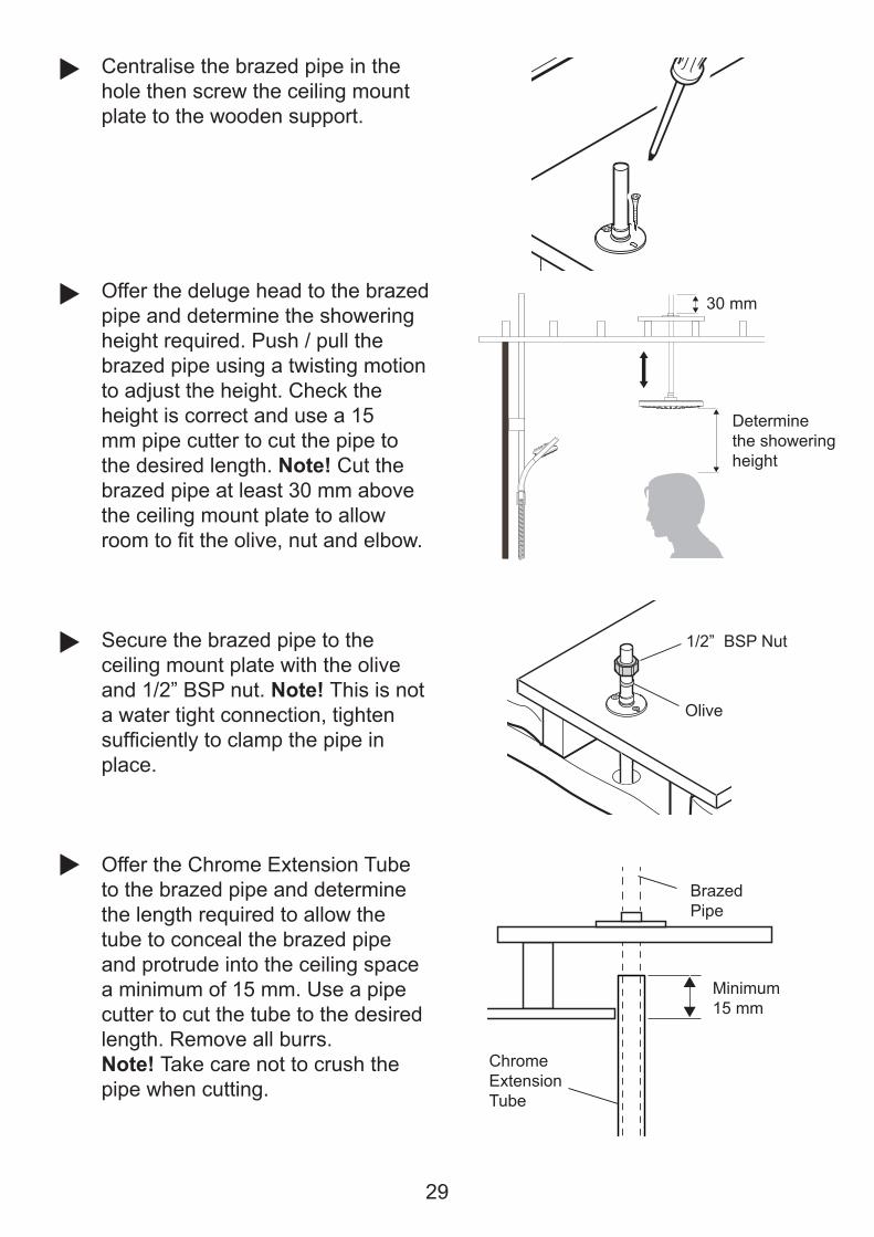
Centralise the brazed pipe in the hole then screw the ceiling mount plate to the wooden support.
Offer the deluge head to the brazed pipe and determine the showering height required. Push / pull the brazed pipe using a twisting motion to adjust the height. Check the height is correct and use a 15 mm pipe cutter to cut the pipe to the desired length. Note! Cut the brazed pipe at least 30 mm above the ceiling mount plate to allow ��������������������%� ���� ����"���
Secure the brazed pipe to the ceiling mount plate with the olive and 1/2” BSP nut. Note! This is not a water tight connection, tighten ������� �������������������� �place.
Offer the Chrome Extension Tube to the brazed pipe and determine the length required to allow the tube to conceal the brazed pipe and protrude into the ceiling space a minimum of 15 mm. Use a pipe cutter to cut the tube to the desired length. Remove all burrs.Note! Take care not to crush the pipe when cutting.
Determinethe showering height
30 mm
BrazedPipe
ChromeExtensionTube
Minimum15 mm
Olive
1/2” BSP Nut

30
Push the cut end of the chrome extension tube into the Ceiling Plate then slide the extension tube over the threaded end of the brazed pipe and up through the hole until the ceiling plate is secured in the hole � ����������� ����������\������� ���the ceiling. Note! If the hole in the ceiling is oversize use silicone sealant on the underside of the ceiling plate to retain it.
Screw the deluge head onto the brazed pipe outlet by hand. Note!Use two suitably sized wrenches to fully tighten (approximately 1/4 turn).
Connect elbow to digital mixer valve. Fit an isolating valve between to enable easy maintenance. (Pipe and isolating valve not supplied). Lock pipe to elbow using clip supplied. Follow manufacturers ������� ����������� ������� ���������[����� ����� ��� ��\��"���pipework.
Connect brazed pipe in ceiling to outlet pipe from digital mixing valve using elbow supplied. Push all parts together fully and lock elbow onto pipe using clip supplied.
{�� ������������������� ����after pipework has been fully \���������������]�������������� �“Commissioning” in Digital Mixer Valve Installation guide.
Slide the extension tube down to conceal the brazed pipe.
Ceiling Plate
Threadedend of pipe
DelugeHead

31
Rear Fed Slide Bar / Showerhead
Decide on suitable position for Slide Bar avoiding buried cables and pipes in wall.
Using template as guide, mark ������ ����������� ������������|����Brackets (600 mm).
Note! Use spirit level to make sure �� ���������������������
{������ �������� ��������
600 mm
Suitable for solid, dry-lined, stud partition, shower cubicle or laminated panel walls.
'��������������������"������������������������� �� �� �����������������������������It should be positioned so that water sprays down the centre of the bath, or away from the opening of a shower cubicle. Water should spray away from the Wireless Controller when the Showerhead is held on the Slide Bar.

32
� ������� ������������������������ �|�������������� �������������{��not fully tighten at this stage. Use template to set correct distances between Wall Brackets. Fully tighten screws.
Note! Slots in Wall Brackets allow for adjustment. Use one horizontal slot and one vertical slot.Make sure that holes for Slide Bar Securing Screws are positioned correctly, as shown.
Position Slide Bar over Wall Brackets and secure with screws. (Do not overtighten.)
Fit Slide Bar End Caps into top and bottom of Slide Bar Assembly. Push and twist caps until they “click” and lock in place.
33
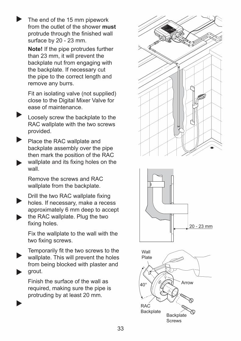
The end of the 15 mm pipework from the outlet of the shower must��������������������� �����������surface by 20 - 23 mm.Note! If the pipe protrudes further than 23 mm, it will prevent the backplate nut from engaging with the backplate. If necessary cut the pipe to the correct length and remove any burrs.
Fit an isolating valve (not supplied) close to the Digital Mixer Valve for ease of maintenance.
Loosely screw the backplate to the RAC wallplate with the two screws provided.
Place the RAC wallplate and backplate assembly over the pipe then mark the position of the RAC ���������� �������� ��������� �����wall.
Remove the screws and RAC wallplate from the backplate.
{�������������]!;������������ ��holes. If necessary, make a recess approximately 6 mm deep to accept the RAC wallplate. Plug the two �� ��������
Fix the wallplate to the wall with the ������ ���������
'�����������������������������������wallplate. This will prevent the holes from being blocked with plaster and grout.
Finish the surface of the wall as required, making sure the pipe is protruding by at least 20 mm.
20 - 23 mm
Wall Plate
RACBackplate
BackplateScrews
Arrow40°

34
Place the backplate over the outlet pipe with the arrow pointing vertically up and tighten the two backplate screws. Make sure that ���������������"��������� �����������surface.
;��������������"�����#����������������inside the backplate nut. Fit the olive and the backplate nut over the outlet pipe, do not tighten the nut fully at this point.
Check that the second ‘O’ seal �"�������������������������������������backplate nut. Press the elbow onto the backplate, make sure that the clips on the elbow engage with the backplate.
To prevent the backplate from ��� � �������������� � ������ ��%����the retaining ring over the backplate nut making sure the slots engage with the screws on the backplate, hold the retaining ring with a wrench while tightening the backplate nut. Remove the retaining ring after use.
Slide the retaining ring over the elbow and engage with the elbow clips. Note! The retaining ring must be engaged correctly to lock the elbow to the backplate, rotate the retaining ring to the position illustrated.
Press the shroud over the elbow, make sure that it engages with the lugs on the backplate.
������������������� �� ���������%���� �������������"����{�� ������showerhead until after pipework has "�� �������\���������������]��������section “Commissioning”.
CopperPipe
Foam Seal
Backplate
Olive
BackplateNut
Backplate
2 x Screws
CopperPipe
Elbow
1
2
Retaining Ring shown correctly engaged with Elbow
RetainingRing

35
Rear Fed Shower Arm and Deluge Head'����������!���� ��{������}�����������"��������������� �� �� �����������������the family. It should be positioned so that water sprays down over the centre of the bath, or away from the opening of a shower cubicle.
The outlet pipe must protrude 18 ���������������������� �����������surface and a minimum 35 mm from the ceiling.Note! Cut the pipe to the correct length and remove any burrs.
Fit an isolating valve (not supplied) close to the Digital Mixer Valve for ease of maintenance.
Mark the positions of the backplate �� ���������Caution! Be aware of hidden pipes or cables
18 ± 2 mm
`��������������������������� ��������for the backplate with a 6 mm drill and insert the wall plugs (supplied). For other types of wall structure ����� �������� �������"����J������(not supplied).Caution! Take care not to drill into hidden pipes or cables.
;����������������"���������������������������� �������������������� ��screws (supplied). Caution! Take care not to damage the ‘O’ Seal in the back of the backplate.
Minimum Distance to Ceiling 35 mm

36
Olive
Compression Nipple
Fit the olive and compression nipple over the outlet pipe and tighten the compression nipple.
ConcealingShroud
CompressionNutOlive
ShowerArm
Fit the concealing shroud onto the shower arm.
Fit the compression nut and olive onto the shower arm.
Fit the shower arm into the compression nipple and tighten the compression nut.
Hand tighten the concealing shroud onto the backplate.
{�� ������������������� ����after pipework has been fully \���������������]�������������� �“Commissioning” in the Dual Outlet Installation Guide.
Screw the deluge head onto the shower arm by hand.Note! Use a suitably sized wrench to fully tighten (approximately 1/4 turn).
Caution! The shower arm is not designed to take weight, therefore care needs to be taken when installing the deluge head.
Shower Arm
Deluge HeadFlow Regulator (some models)
Backplate

37
Wireless ControllerSuitable for solid, dry-lined, stud partition, shower cubicle or laminated panel walls.
'���|��������;� ���������������"������������������������� �� �� �����������������the family. It should be positioned so that water does not spray over it when the Showerhead is held on the Slide Bar.
Important! Make sure wireless signal has been tested between Wireless �������������������������<��@��\�������������J��������?�����'���section ‘INSTALLATION - Digital Mixer Valve: Position and Signal Test’.
Mark position for backplate holes. $�� ��"��������� �\�����������(e.g. Centre of tile).Drill and plug holes.
Caution! Avoid drilling through buried cables or pipes.
Make sure surface is clean and �����`��"������������ �����������surface.
Turn controller over and remove the battery cover by loosening the 4 screws with a pozi drive screwdriver. Note! The screws remain attached to the battery lid.
# ������ ���"����������������������and type. Do not use rechargeable batteries. Replace all three batteries at the same time.
Hook Controller on top of backplate � ������������� ����;� ��������“clicks” back into place.

38
Press “ ” button and reduce temperature to full cold “CLd”. ]���[?�����?� ����������Q��Low Pressure (pumped) version, let shower run in order to prime the pump. For long pipe runs, let the shower run to allow the pump to prime until a steady stream of ?�����[? �
Caution! Risk of product damage. Do not run Pumped Valve (low pressure version) without a water supply for longer than 15 minutes during priming.
�+��%''%+^%^&
Connect battery to Wireless Controller, display appears.
Make sure the end of the hose is in either the bath, shower tray or other water catchment area.Note! The overhead mounting will [?�?�����?��� ?�������� �(“ 1 ” or “ 2 ”) depending on the ����������\������������
Important! Ensure the Digital Mixer Valve is registered refer to section ‘ INSTALLATION - Digital Mixer Valve: Position and Signal Test’.
Turn on electrical supply to Digital Mixer Valve.
1

39
Run cold water through (approximately 2 minutes) and check entire installation for water leaks. Press “ ” to turn shower off. Fit the second hose washer and showerhead.
Press “ ” to turn shower on. Test operation of shower by increasing/decreasing both ���������������[?����� ��_'���" ���&������������������� �`
Test operation of showerhead spray modes. (See Showerhead " ���&������������������� �`
Repeat process for outlet 2 by pressing “ 2 ” button.
1
1
��������" ���&����������������� ������ ���?���� ������ �?���
The Wireless Controller factory default settings are as follows:Maximum Showering Temperature = 45°CEco Mode = OffWarm-Up Mode = OffClock = 10:00 (when batteries connected)Clock Display = OnShower Duration = OffBath Fill Mode = Off
Note! If the display reads 4:00 when the batteries are connected the wireless controller will require registering, refer to the initial registration process in section “ Digital Mixer Valve: Position and Signal Test”.

40
If the wireless controller has previously been assigned to a digital mixer (indicated by 10:00 display on wireless controller) and communication problems are encountered, a re-registering of the wireless controller may be required.
A re-registering of the wireless controller must also be performed should the control PCB in the Digital Mixer Valve be replaced.
To re-register the wireless controller to the Digital Mixer carry out the following sequence.
Isolate power to the digital mixer valve.
Press “ ” and “ ” buttons simultaneously until “End” is displayed on the screen.
Restore power to the digital mixer valve.
����\������������� ��� ���� ��buttons, “SET” will be displayed on the screen. Note! if display reads “Err” press “ ” and repeat the process.
+
+
Note! Re-registering can only be performed if the wireless controller has previously been assigned to a digital mixer. This is indicated by the clock time default 10:00 (when batteries are connected).
�#��#&%']#�%^&
1
1
1

41
Q=">]��%=&^+'%'Read the section “Important Safety Information”������
Providing the Digital Mixer Valve has been correctly installed and is operated in ������� ������������� �������� ���� ��� ���� �����������%�������������������� ���������
If any maintenance is required then it must be carried out by a competent tradesperson. Before replacing any parts make sure that the underlying cause of ��������� ���� �����"�� ���� ������
Warning! There are no user serviceable components beneath the cover of the appliance. Only a competent tradesperson should remove the cover.
Symptoms Probable Cause Possible RemedyNo display. The bat ter ies are f lat or
� ����������������Check and rectify.
Canno t ass ign Wi re less Controller to Digital Mixer Valve.Out of range symbol is displayed
No power to Digital Mixer Valve.
Pos i t ion and s igna l tes t incomplete.
Reassignment required.
Digital Mixer Valve failure.
Wireless Controller failure.
Radio frequency interference
Check electrical connection and supply.
Repeat registration sequence.
Refer to “Re-Registering”.
Contact Kohler Mira Ltd.
Contact Kohler Mira Ltd.
E n s u r e a l l o t h e r r a d i o transmitting devices, including mobile phones, are switched off.R e p e a t c o m m i s s i o n i n g sequence.

42
Symptoms Probable Cause Possible Remedy������� ��������\��%�{�������Mixer Valve not turning on.
Rotary control not functioning correctly, temperature display not changing when rotating bezel.
Wireless Controller.
Controller not assigned to Digital Mixer Valve.
Faulty Wireless Controller
Repeat commissioning sequence.
Contact Kohler Mira Ltd.
Digital Mixer Valve.
No power to Digital Mixer Valve.
Isolators closed.
Filters blocked.
Digital Mixer Valve installed above cold water storage cistern. (LP Pumped valve only).
Air trapped in plumbing.
Check electrical connection and supply.
Open isolators.
;��� ��������
Appliance is not suitable for negative head installation. Refer to section “INSTALLATION Typical Suitable Installations.”
Rearrange pipework to avoid airlock forming. Refer to section “INSTALLATION Typical Suitable Installations.”
Shower Fitting / Other.
Blocked Showerhead.
Water pressure is low.
Fluctuating water temperature.
Clean/descale Showerhead.
Check f low rate is above stated minimum. Refer to |'���������}.
Make sure inlet temperature ������� ����������������� ���]�����to section “SPECIFICATIONS”

43
Symptoms Probable Cause Possible Remedy� �����������\������� ��temperature.
Wireless Controller.
Radio interference. Change controller frequency channel. Refer to " ���&�����- “Control Frequency”.
Warm-Up feature is being used with combi-boiler.
Disable Warm-Up feature. Refer to " ���&�������|�����Up”.
Digital Mixer Valve
`��������������� ������������system using combi-boiler.
`������������\���regulators. Refer to “Useof Flow Regulators with Combination Boilers”.
Shower Fitting/Other
Shower temperature affected by use of adjacent hot/���������� ������� ����������pipework to feed both Digital Mixer Valve and taps at same time.
Increase pipe sizes or separately feed shower. Refer to plumbing system diagrams under “Installation” for correct connection method.
`�������� �������������\���
Refer to " ���&�������|Q�����Diagnosis”.
Filters blocked.
Water pressure too low.
Flow rate is too low.
Fluctuating water temperature.
;��� ��������
Check maintained pressure is within recommended range. Refer to |'��������� }.
;�����\������������������ �recommended range. Refer to |'��������� }.
Check inlet temperatures are within recommended range. Refer to |'��������� }.
Maximum blend temperature too hot or too cold.
Incorrect maximum temperature setting.
Refer to Function F1 - “Maximum Shower Water Temperature” in User Guide
;� �� �����\����������������not shut off.
Wireless Controller or Digital Mixer Valve failure.
Isolate power and water supplies. Contact Kohler Mira Ltd.

44
Symptoms Probable Cause Possible RemedyShower runs for a short time ����[�������� ������� �\���reduces, splutters or stops. Worst when other hot taps are in use. Less evident when shower is on full cold.
Air is being sucked down the vent pipe. (Gravity fed system).
Warm up setting inadvertently selected.
The hot draw off pipe is positioned too high in relation to the lowest water level of the cold water cistern (100 mm min, refer to |&��@��J�Q���Showers” diagram. Consider increasing size of cold feed pipe to cylinder to 28 mm diameter.
Disable Warm-Up feature. Refer to " ���&�������|�����Up”.
Shower runs for a short time (3 - 5 minutes)
;����� ���������� ������� ��(230 litres minimum required).
Eco setting selected.
“Shower Run Time” enabled.
“Bath Fill Mode” enabled.
Increase cistern size.
Disable Eco feature. Refer to ‘Function Menu’ - “Eco”.
Increase shower run time or disable feature. Refer to ‘Function Menu’ - “Shower Run Time”.
Disable Bath Fill feature. Refer to ‘Function Menu’ - “Bath Fill Mode ”.
Shower runs cool aftera short time (1 - 2 minutes)��� �\��splutters.
Air ingress into hot pipework. Refer to plumbing system diagrams under“Installation” for correct connection.
Shower runs cold after5 - 10 minutes. ( LP Pumped valve only).
� ������� ������������hot water in cylinder.
Increase storage of hot water.

45
Isolate the electrical and water supplies to the Digital Mixer Valve, � ���� �� ������������ �������������pressure and to assist the draining of residual water.
Unscrew plastic nuts and either withdraw pipework or remove Digital Mixer to gain access to the ����������������������� ���������
_���\���"��������������������carefully lever cartridges out.
]�������������� ������ ����renew. Clean or renew checkvalve cartridges if required.
]���������%������ ��������� ������������� ������J������� �������� � ��� ���
Restore water supply and electrical supply. Test shower and check for leaks.
MAINTENANCEGeneral]�������������� �������� ���������� �������� �������Before replacing any parts ensure that the underlying cause of the malfunction has been resolved.If the shower is dismantled during installation or servicing then upon completion the product must be inspected to ensure there are no leaks.Warning! There are no user serviceable components beneath the cover of the appliance. Only a competent tradesperson should remove the cover.CleaningMany household cleaners contain abrasives and chemical substances, and should not "��������������� � ���������������������� ����'������ �������������"������ ��������a mild washing up detergent or soap solution, and then wiped dry using a soft cloth.Checkvalve Cartridges and Filters - Removal and InstallationHot water entering the cold supply, or vice versa, indicates that immediate attention is necessary. This is carried out by removing and cleaning, or renewingas necessary, the checkvalve cartridges.

46
SPARE PARTS
*�����*������������[��;��� � ������ �������!�*�����*�������������[�;��� � ������ ���������
1796.140Control PCB
1666.223Aerial
1666.199Inlet/OutletConnector (x1)
1666.209Inlet Cartridge+ Filter (x1)
1666.225Push Fit Isolator
1666.210Thermistor
1796.143Mixing Valve & Outlet 2 Assembly
1796.139Mains Cable
A
A
B
B(x 7)
A
Digital Mixer - High Pressure / Combi Valve
A
1664.123Stepper Motor Extension Lead
1664.123SolenoidExtension Lead
1666.215Flow Regulator

47
*�����*������������[�;��� � ������ �������!�*�����*�������������[�;��� � ������ ���������*����*������� ����[�;��� � ������ �������;�*����*���� ��#���������� ����[�;��� � ������ �������{�
Digital Mixer - Pumped Valve
1666.199Inlet/OutletConnector (x1)
1666.209Inlet Cartridge+ Filter (x1)
1666.195Pump Assembly
1666.192Mixing Valve AssemblyIncludes:166.199 (x3)1666.209 (x2)1666.210 (x1)
1666.210Thermistor
1666.224Aerial
1666.194Transfer Tube
1666.198Outlet Tube (x1)Includes:1666.194
1666.196Outlet Clamp
1796.136Solenoid Cable
1796.137Control PCB
1796.135Mains Cable
1666.225Push Fit Isolator
B(x7)
C
A
A
D
A, C
A, D

48
Shower Fittings - Showerhead
1603.104Shower Hose
1688.187Slide Bar Support
1688.187Slide Bar Support
1688.196PipeConnection Pack
1688.198Wall Spacer (x2)
1688.191Upper Support
1799.015Concealing Plate
1688.195Supply Tube
632.73Hose Washer (x2)
1688.312Installation Template
1688.167BurstAssembly
1688.282Checkvalve
1688.185ClampBracket
1688.193Slide Bar
1595.035RAC Shroud
1688.201360M Showerhead
B
B
B
A
A
A
A
*����*��������� ��������������[��;��� � ������ ����������*����*���;�������`���� ���;��� � �������[�;��� � ������ �������!��
450.20RAC Pack
A
1688.194ChromeSupply Tube
1688.165CloudAssembly
1688.161Rain Assembly
1688.163Storm Assembly

49
Shower Fittings - Deluge Head
1799.009Rigid Arm
1688.196PipeConnectionPack
1799.014Ceiling Mount Plate
1799.014Ceiling Plate
1799.013BrazedPipe
1656.131BackplateAssembly
1799.007Deluge Head
1799.016Deluge Fittings Component Pack
1688.194Chrome Supply Tube
Digital Mixer - User Interface
1796.133Wireless Controller
1796.142Backplate(Includes Screws & Wallplugs)
1796.141Battery Lid (Includes Screws)

50
ACCESSORIESGenuine Mira accessories can be purchased direct from Customers Services (our contact details can be found on the back cover of this guide) or from approved stockists or merchants.
Shower SeatWhite - 2.1536.128White/Chrome - 2.1536.129For use in or out of the showering area. Folds up when not in use.Maximum User Weight - 127 kg (20 stone) Note! Must be installed onto a solid wall.
Premium Shower SeatWhite/Chrome - 2.1731.001&��J*������������������Stylish, slim-line and robust shower seat for use in or outside of the shower area. Folds up when not in use. Maximum User Weight - 150 kg (23.5 stone) Note! Mustbe installed onto a solid wall.
�����'�������&��\�;�� 300 mm - 2.1605.070450 mm - 2.1605.071600 mm - 2.1605.072Premium grade, highly polished, stainless steel grab bars. Note! Must be installed onto a solid wall.
Wireless Controller Black/Chrome - 1.1796.007Wireless Controller available as a complete accessory if more than one controller is required. Comes complete with batteries and wall �� ����'����"�������� �����������Install and test in accordance with the instructions contained within this guide.

51
End of Product Life
When this appliance has reached the end of its serviceable life, it should be disposed of in a safe manner, in accordance with current local authority recycling, or waste disposal policy.
Batteries
Spent batteries should not be disposed of with normal household waste. Contact your local authority for information on waste disposal and recycling.
This symbol on the product or its packaging indicates that this product should not be disposed of with your other household waste. Instead, it is your responsibility to dispose of your waste equipment by handing it over to a designated collection point for the recycling of waste electrical and electronic equipment. The separate collection and recycling of your waste equipment at the time of disposal will help to conserve natural resources and ensure that it is recycled in a manner that protects human health and the environment. For more information about where you can drop ����������������J���� ������������� �%��������� ������������������� ���������%������household waste disposal service or the shop where you purchased the product.
�%'�+'=>�=^���#���>%^&

521199702-W2-A (L15F, N85K, N85L, N86F) (1796) © Kohler Mira Limited, September 2012
Mira is a registered trade mark of Kohler Mira Limited.
The company reserves the right to alter product specifi cations without notice. FM 14648
GuaranteeYour product has the benefit of our manufacturer’s guarantee which starts from the date of purchase.To activate this guarantee, please return your completed registration card, visit our website or free phone 0800 0731248 within 30 days of purchase (UK only).
Within the guarantee period we will resolve defects in materials or workmanship, free of charge, by repairing or replacing parts or product as we may choose.This guarantee is in addition to your statutory rights and is subject to the following conditions: ● The guarantee applies solely to the original installation under normal use and to the original purchaser only. The product must be installed and maintained in accordance with the instructions given in this user guide. ● Servicing must only be undertaken by us or our appointed representative. Note! if a service visit is required the product must be fully installed and connected to services. ● Repair under this guarantee does not extend the original expiry date. The guarantee on any replacement parts or product ends at the original expiry date. ● For shower fi ttings or consumable items we reserve the right to supply replacement parts only.The guarantee does not cover: ● Call out charges for non product faults (such as
damage or performance issues arising from incorrect installation, improper use, inappropriate cleaning, lack of maintenance, build up of limescale, frost damage, corrosion, system debris or blocked fi lters) or where no fault has been found with the product.
● Water or electrical supply, waste and isolation issues. ● Compensation for loss of use of the product or
consequential loss of any kind. ● Damage or defects caused if the product is repaired
or modifi ed by persons not authorised by us or our appointed representative.
● Routine maintenance or replacement parts to comply with the requirements of the TMV 2 or TMV 3 healthcare schemes.
● Accidental or wilful damage. ● Products purchased ex-showroom display.
What to do if something goes wrongIf your product does not work correctly refer to this manual for fault diagnosis and check that it is installed and commissioned in accordance with our instructions.If this does not resolve the issue, contact us for help and advice.Extended GuaranteesA selection of protection plans are available that enable you to cover repair bills (excludes Eire). Ring 01922 471763 for more details.
01 459 1344
Mira Customer Services Dept, Cromwell Road, Cheltenham, Gloucestershire, GL52 5EP
Helpdesk Service - Ring our Customer Services Team for product advice, to purchase spare parts or accessories or to set up service visit. You can contact us via phone or e-mail, details below. Please provide your model name, power rating (if applicable) and date of purchase.Mira Showers Website (www.mirashowers.co.uk)Visit our website to register your guarantee, download user guides, diagnose faults, purchase our full range of accessories and popular spares, or request a service visit.Spares and Accessories - We hold the largest stocks of genuine Mira spares and accessories. Contact us for a price or visit our website to purchase items from our accessory range and popular spares. Service/Repairs - No one knows our products better than our nationwide team of Service Technicians. We can carry out service or repair work to your product both during and after the guarantee period. Ask about our fi xed price service repairs.
To Contact Us: UK
Fax: Dublin 01 459 2329
CUSTOMER SERVICE
E-mail: Visit www.mirashowers.co.uk/contactus
To Contact Us: Eire Only
Modern Plant Ltd (Dublin),Otter House, Naas Road, Clondalkin, Dublin 22
0844 571 5000
Fax: 01 242 282595
E-mail: [email protected]

1
These instructions must be left with the user
User Guide
Mira Platinum Dual

2
GeneralThank you for purchasing a quality Mira product. To enjoy the full potential of your new product, please take the time to read this guide thoroughly and keep it handy for future reference.
The Mira Platinum Dual Wireless Controller is a remote user interface and controls the following functions:
�� Maximum Showering Water Temperature�� Eco Mode�� Warm-Up Mode�� Clock�� Flow Range�� Shower Run Duration�� Bath Fill Mode
This guide covers the setting and use of these functions and includes a trouble shooting guide should the appliance not function as expected. For issues relating to the installation of the appliance or other associated products, please refer to the relevant Installation Guide (s) or contact our Customer Services Team. (Details in the back of this guide.)
NOTE! ALL FUNCTIONS ARE ONLY AVAILABLE AFTER THE CONTROLLER HAS BEEN ASSIGNED TO A MIRA PLATINUM DUAL DIGITAL MIXER VALVE. (See Mira Platinum Dual Outlet Installation Guide.)
INTRODUCTION
SAFETY INFORMATION1. Make sure that you fully understand how to operate this shower and make sure
that it is properly maintained in accordance with the instructions given in this manual.
2. Sunburn or skin conditions can increase your sensitivity to hot water. Make sure that you set the shower to a cooler temperature.

3
Turn Outer RingShowering Water Flow Adjustment
Decrease Flow
Increase Flow
Increase Temperature
Decrease Temperature
Display Outlet 2 Start/Stop
Outlet 1 Start/Stop
CONTROL LAYOUT

4
Flow Display
Low Battery Display
Control Out Of Range
Temperature Display
Clock Display
Economy Flow Display
DISPLAY SYMBOLS
Outlet 1 Selected
Outlet 1 Selected
CountdownMode Enabled

5
Press “ ” or “ ” to start or stop shower.
����������� ������������������������������������� �
After a short period, display will dim to help extend battery life.
Approximately 5 seconds after shower has stopped, display will turn off automatically.
Shower will not run continuously for more than 30 minutes before stopping automatically (5 minutes when “ECO” function is set to “on”) Note! The shower ������������������� ���� ����������������������������������
When “Warm-Up” function is “on”, there will be a short delay (5 seconds) before ���������������������
USING THE SHOWERSwitch On/Off
1 2

6
Adjust Temperature
While shower is running, press “ + ” or “ - ” to adjust temperature. Showering temperature appears on display in degrees Celsius (°C).
Adjust Flow
������������������������������������������ �����������������������������appears on display in white segments.

7
FUNCTIONS
F1 - Maximum Showering Water Temperature. Adjustable per outlet, this is the temperature the shower cannot go beyond when in use.F2 - Eco. The shower will stop automatically after 5 minutes. When this setting is enabled, maximum available showering ���� ��� ����� � �� ���� ��� ���� ��������produced. “ECO” symbol is displayed. When setting is “off”, maximum showering �����������������������!ECO” symbol goes ��������������������������������� �F3 - Warm-Up. When this setting is enabled and the shower is started, there is a short delay (5 seconds) before water ����� � � ��������� ������ ����� ����to indicate shower is waiting for selected display temperature to be achieved. The shower stops when temperature has been reached and shower is ready for use, press “ ” as normal. If temperature cannot be found, shower will stop automatically after 5 minutes.Temperature display does not flash if “Warm up” has not been enabled, shower operates as normal.Note! When used with some combination boilers, the warm-up function may be impaired. This is due to the functional nature of combination boilers.F4 - Clock Setting. To set the time.F5 - Clock Display. When Clock Display is “on”, time is displayed when shower has stopped, or after 10 seconds of inactivity whilst the shower is running. When Clock Display is “off”, the time is replaced by the showering temperature.
The following functions can be altered individually to adjust how the shower operates:
on off
F6 - Flow Range.�"�����������#����$�������%&�����'������������������������������rate (showering force) can be adjusted to within a desired range by setting a low point and a high point. During adjustment the shower will need to be started.
1

8
F7 - Control Frequency. An unreliable functioning of the appliance (not always able to change settings of shower) may indicate radio interference by another device transmitting locally on same channel. Changing channel may resolve this problem.F8 - Count Down Display Enable. If enabled, the remaining shower time is shown instead of the clock. During the countdown the outer display segments will fade while passing through the full 360° but re-illuminate as each minute elapses, the Wireless User Interface will emit a single beep when 2 minutes are left on ������� ����� �*��������� ��������������������"����������+9������ �����showering the display is fully illuminated.F9 - Shower Run time. If previous function (F8 - Count Down Enable) has been activated the operating duration of the shower can be adjusted in 1 minute increments of between 1 - 30 minutes.F10 - Bath Fill Mode. Enables or disables bath fill mode, when bath fill mode is enabled the following features are available:Bath Fill Duration and Temperature ;������������������������� ����������to be adusted.�� Bath Fill Duration - 1 - 20 minutes�� Bath Fill Temperature - 30° - 48°CBath Fill Learn Mode. Allows the Wireless User Interface to memorise both the temperature of water and the time duration required for the digital mixer valve to supply water to the bath.

9
Use “+” or “-” to cycle through functions, press “ ” to enter a function.
Press and hold “+” and “ 1 ” buttons simultaneously for approximately 5 - 10 seconds until “End” is displayed on the unit. The function menu can now be entered.
(See following sections in this guide for details on each function and how to alter their settings.) Note! If signal loss occurs during a function change, “Err” will appear on display.Press “ ” to clear and retry function change.
FUNCTION MENUEnter the Function MenuNote! If the display of the Wireless User Interface is asleep press buttons “+” and “ ” simultaneously to ‘wake’ it before attempting to enter Function Menu.
1
1
1

10
Exit the Function Menu
=���������� >�����!+” or “-” buttons to cycle back through functions until “End” appears. Press “ ” to exit.
Control is ready to use within 10 seconds of exiting the menu.
If necessary, test shower to see if functions are working as expected.
1

11
Press “ ” to confirm the outlet you wish to set the maximum showering temperature to.
Press “+” or “-” to adjust temperature.Maximum = 48°CMinimum = 38°C
Factory default “45°C”.
Press “ ” to set.
Press “ ” to exit back to Function Menu. See section “Exit the Function Menu”.
CHANGING FUNCTIONS/SETTINGSMaximum Showering Water Temperature
Cycle menu to “F 1” and press “ ” to enter, then press “+” or “-” to toggle between which outlet you wish to set the maximum showering temperature to. The outlet selected will be indicated on the display.
1
= Outlet 1
= Outlet 2
1
1
1

12
Press “+” or “-” to change setting “on” or “off”.
Factory default “off”.
Press “ ” to exit back to Function Menu. See section “Exit the Function Menu”.
Cycle menu to “F 2 ” and press “ ”.
Press “ ” to set.
Eco
1
1
1

13
Warm-Up
Factory default “off”.Note! Function will not work with combination boilers.
Press “ ” to exit back to Function Menu. See section “Exit the Function Menu”.
Cycle menu to “F 3 ” and press “ ”.
Press “ ” to set.
1
1
Press “+” or “-” to change setting:
1
Selected outlet will warm up.
Both outlets will warm up, regardless of whether outlet “ 1 ” or “ ” has been selected.
Warm up function disabled.

14
Clock Setting
Press “-” to change hour setting.Hours will count downwards.
Press “+” to change minute setting.Minutes will count upwards.
Cycle menu to “F 4 ” and press “ ”.
Press “ ” to set time and exit back to Function Menu. See section “Exit the Function Menu”.
Factory default “04:00” (“10:00” once successfully paired to a digital mixer valve and batteries removed / re-inserted)
1
1

15
Clock Display
Cycle menu to “F 5 ” and press “ ”.
Press “+” or “-” to change setting “on” or “off”.
Factory default “on”.
Press “ ” to set.
Press “ ” to exit back to Function Menu. See section “Exit the Function Menu”.
1
1
1

16
Flow Range
For use with High Pressure / Combi Valve version only.Factory default “1 - 99”
“on” is displayed, press “ ” to start shower.
Note! To exit before commencing “Flow Range” adjustment press “ ” and “ESC” �������� ������ >�������!�����!����������exit.
Lower l im i t i s d i sp l ayed , e .g . “L 1”. Turn the chrome outer ring to adjust ������ ����� ������������+?@@�
Press “ ” to set lower limit.
1
Press “ ” to confirm the outlet you wish to set the flow range to.
Cycle menu to “F 6” and press “ ” to enter, then press “+” or “-” to toggle between which outlet you wish to adjust the flow range of. The outlet selected will be indicated on the display.
= Outlet 1
= Outlet 2
1
1
1
1

17
Higher l im i t i s d i sp layed , e .g . “H 99”. Turn the chrome outer ring ���������� ����� �������������+?@@��(Most plumbing systems may achieve �J����������������@@�K
Press “ ” to set higher limit.
Press “ ” to exit back to Function Menu. See section “Exit the Function Menu”.
1
1
18
Control Frequency
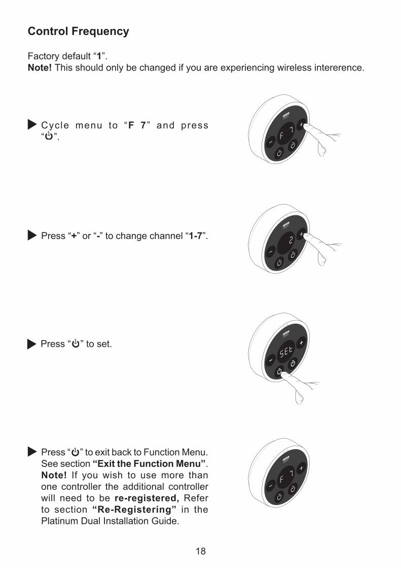
Cycle menu to “F 7 ” and press “ ”.
Press “+” or “-” to change channel “1-7”.
Factory default “1”.Note! This should only be changed if you are experiencing wireless intererence.
Press “ ” to set.
Press “ ” to exit back to Function Menu. See section “Exit the Function Menu”.Note! If you wish to use more than one controller the additional controller will need to be re-registered, Refer to section “Re-Registering” in the Platinum Dual Installation Guide.
1
1
1

19
Countdown Enable
Factory default “off “.
Cycle menu to “F 8 ” and press “ ”.
Press “+” or “-” to change setting “on” or “off ”.
Press “ ” to exit back to Function Menu. See section “Exit the Function Menu”.
Press “ ” to set.
1
1
1

20
Shower Run Time
Factory default “30 minutes“.
Cycle menu to “F 9 ” and press “ ”.
Press “ ” to exit back to Function Menu. See section “Exit the Function Menu”.
Press “ ” to set.
Press “+” or “-” to change the amount of time the shower will run before switching itself off. Adjustable between 1 - 30 minutes.
1
1
1

21
Bath Fill Mode
Factory default “off ”.
Press “ ” to exit back to Function Menu. See section “Exit the Function Menu”.
Press “ ” to set.
Cycle menu to “F 10” and press “ ”.
Press “+” or “-” to toggle between options “on” ,”Lrn” and “off”. Note! selecting either ‘on’ and ‘Lrn’ will enable further options in the function menu:
1
1
1
= see “Bath Fill Duration and Temperature”
= see “Bath Fill Learn Mode”
= continue below

22
Bath Fill Duration and Temperature - (ON)
Press “ ” to select.
Cycle through menu and set “Bath Fill Mode” to “on”.
Press “+” or “-” to toggle between which outlet you have selected to use as a bath fill. The outlet selected will be indicated on the display.
Press “+” or “-” to change the amount of time the digital mixer will supply water ���������������� ���������������press “ 1 N�����������Adjustable between 1 - 20 minutes.
1
= Outlet 1
= Outlet 2

23
Press “+” or “-” to adjust the temperature of the water supplied to the outlet selected as a bath fill. Adjustable between 30° - 48°C. Note! The maximum temperature set in function "�+����������������J��������������outlet temperature in Bath Fill Mode.
Press “ ” to set.
Press “ ” to exit back to Function Menu. See section “Exit the Function Menu”.
1
1

24
Bath Fill Learn Mode - (Lrn)
Note! ����������������������������Q��"���������������������������������
Press “ ” to select the outlet, “on” is displayed.
Cycle through menu and set “Bath Fill Mode” to “Lrn”, press “ ” to select.
Press “+” or “-” to toggle between which outlet has been selected as a bath fill. The outlet selected will be indicated on the display.
Press “ ” and the selected digital mixer valve outlet will open and water ��������>�!Lrn” and the outlet selected are displayed.
1
= Outlet 1
= Outlet 2
1
1

25
Note! To exit at any stage of “Bath Fill Learn Mode” press “ ” and “Esc” will ��� ������ >�������!� N��������������wish to exit and the wireless controller will return to the “F 10” screen.
Press “+” or “-” to adjust temperature.Maximum = 48°CMinimum = 30°C
When the water has reached the desired level and temperature press “ ” to store the information.
Press “ ” to exit back to Function Menu. See section “Exit the Function Menu”.
1
1
1

26
REPLACING THE BATTERIESChange the batteries when the low battery symbol is displayed.
To access the batteries, the controller must be removed from the wall.
Press button to release and remove the controller from the wall.
Make sure the controller is dry before removing the battery cover. Turn unit over to remove the battery cover by loosening the 4 screws with a pozi drive screwdriver.Note! The screws remain attached to the battery lid.
Remove and replace all batteries. Make sure all 3 replacement batteries are of the same brand and type. Do not use rechargeable batteries.
When refitting the battery cover, make sure the blue seal is clean of dirt and debris. Make sure the ������ ��� ������ � �����>� ��� �� ���overtighten the screws.
Hook controller on top of bracket and ����� ������ ����� ���������� !������N�back into place.
If necesary, test shower to see if functions are working as expected.

27
Error Codes;������������������������������������������������������������������������������������ �������� ������ ������������������� ����������������������“Err” followed by the error code number.
Over Temperature at Control Sensor (E3 - E7)1. Turn Digital Mixer off for 10 seconds. Turn back
on and allow 15 seconds to reset.2. If shower operation does not return to normal,
make sure hot and cold inlets are not reversed.3. If shower operation does not return to normal,
��������������������� ���������������� ����are clean.
4. If shower operation does not return to normal, check the water supplies to the valve are within the correct temperature and pressure ranges. See “Mira Platinum Installation Guide - �����������”.
5. If problem still occurs, make a note of the error code and contact our Customer Services Team.
Control Sensor (E4)1. Turn Digital Mixer off for 15 seconds. Turn back
on and allow 15 seconds to reset.2. If shower operation does not return to normal,
replace Thermistor. (To be performed by competent tradesperson only!)
3. If problem still occurs, make a note of the error code and contact our Customer Services Team.
Control Sensor or PCB Relay (E36)1. Turn Digital Mixer off for 15 seconds. Turn back
on and allow 15 seconds to reset.2. If shower operation does not return to normal,
replace Thermistor. (To be performed by competent tradesperson only!)
3. If shower operation does not return to normal, replace PCB. (To be performed by competent tradesperson only!)
4. If problem still occurs, make a note of the error code and contact our Customer Services Team.
FAULT DIAGNOSIS

28
Replace batteries.
Displayed if there is a signal loss between the Wireless Control Unit and the Digital Mixer whilst a function setting is being altered. Or, If the valve is not ready wait for 10 seconds after entering programming menu.
Error During Function Change
Digital Mixer Temperature Motor (E61)1. Turn Digital Mixer off for 15 seconds. Turn back
on and allow 15 seconds to reset.2. If shower operation does not return to normal,
check and, if necessary, replace Mixer Valve. (To be performed by competent tradesperson only!)
3. If problem still occurs, make a note of the error code and contact our Customer Services Team.
Digital Mixer PCB Error.1. Turn Digital Mixer off for 15 seconds. Turn back
on and allow 15 seconds to reset.2. If problem still occurs, make a note of the error
code and contact our Customer Services Team.
Control out of range.
Press “ 1 ” to clear the display and retry the function change.

29
General Faults
Malfunction Cause RemedyNo display. �������������������
������������� �Check and rectify.
Shower will not operate. Water supply isolated.
Flat batteries.
Electrical supply isolated or fuse blown.
No connection to Digital Mixer. Control out of range.
Digital Mixer malfunction.
Check water supply.
Replace batteries.
Check electrical supply. If fuse blown, replace Digital Mixer Valve PCB.
Reset and recommission. Refer to Installation Guide
Isolate electrical supply and reset after 30 seconds
If problem persists, contact our Customer Services Team.
Y����������������������Shower Fittings.
Showerhead blocked.
Faulty Checkvalve in Showerhead.
Hose blocked or twisted.
Digital Mixer malfunction.
“L” and or “H” values set too low in Flow Range (F6).
Check and clean.
Check and clear or replace Checkvalve.
Check and clean or release twist.
Contact our Customer Services Team.
Change to higher setting.
Drip from Showerhead. A small amount of water may be retained in showerhead after showering. This may drain over a few minutes.
This is normal. Changing position of Showerhead may vary draining time.
Shower not hot enough. Maximum showering temperature set too low.
Z�����[�J����� ������������
Increase maximum showering temperature (Function F1).Make sure hot and cold water supplies are connected correctly and delivering a ����������� ����������within the required limits. See “�����������” in the “Mira Platinum Dual Outlet Installation Guide”.
If problem persists, contact our Customer Services Team.
\�������������������temperature.
Controller out of range.
Radio interference.
Warm up feature is being used with combi-boiler.
Refer to “Fault Diagnosis” in the “Digital Mixer Installation Guide”.
+
+

30
"������������� ��� ����� Filters blocked.
Water pressure too low.
Flow rate is too low.
Fluctuating water temperature.
Refer to “Fault Diagnosis” in the “Digital Mixer Installation Guide”.
Maximum blend temperature too hot or too cold.
Incorrect maximum temperature setting.
Refer to “Maximum Shower Water Temperature” in the “Digital Mixer Installation Guide”.
&��������������������������not shut off.
Wireless Controller or Digital Mixer Valve failure.
Isolate power and water supplies. Contact our Customer Services Team.
Shower runs for a short time ^_9�?�`9������ �K���������reduces, splutters or stops. Worst when other hot taps are in use. Less evident when shower is on full cold.
Air is being sucked down the vent pipe. (Pumped product / gravity fed system).
Warm up setting inadvertently selected.
The hot draw off pipe is positioned too high in relation to the lowest water level of the cold water cistern (100 mm min, refer to “Gravity Fed Showers” diagram in the “Digital Mixer Installation Guide”. Consider increasing size of cold feed pipe to cylinder to 28 mm diameter.
Disable Warm-Up feature. Refer to ‘Function Menu’ - “Warm-Up”.
Shower runs for a short time (3 - 5 minutes)
&�����������������������(230 litres minimum required).
Eco setting selected.
“Shower Run Time” enabled.
“Bath Fill Mode” enabled.
Increase cistern size.
Disable Eco feature. Refer to ‘Function Menu’ - “Eco”.
Increase shower run time or disable feature. Refer to ‘Function Menu’ - “Shower Run Time”.
Disable Bath Fill feature. Refer to ‘Function Menu’ - “Bath Fill Mode ”.
Shower runs cool aftera short time (1 - 2 minutes) ����������������
Air ingress into hot pipework. Refer to plumbing system diagrams under “Installation” in the “Digital Mixer Installation Guide”.for correct connection.
Shower runs cold after5 - 10 minutes.
\����������������������water in cylinder.
Increase storage of hot water.

31
End of Product Life
When the appliance has reached the end of its serviceable life, it should be disposed of in a safe manner and in accordance with current local authority recycling or waste disposal policy.
Batteries
Spent batteries should not be disposed of with your normal household waste. Contact your local authority for information on waste disposal and recycling.
Many household cleaners contain abrasives and chemical substances, and ����� ���������� ����������������������� �������������������������������should be cleaned with a mild washing up detergent or soap solution, and then wiped dry using a soft cloth.
This symbol on the product or its packaging indicates that this product should not be disposed of with your other household waste. Instead, it is your responsibility to dispose of your waste equipment by handing it over to a designated collection point for the recycling of waste electrical and electronic equipment. The separate collection and recycling of your waste equipment at the time of disposal will help to conserve natural resources and ensure that it is recycled in a manner that protects human health and the environment. For more information about where you can drop ��������������{��������������������>�����������������������������������>������household waste disposal service or the shop where you purchased the product.
CLEANING
DISPOSAL AND RECYCLING

32
CUSTOMER SERVICE
1199703-W2-A (N86F) (1796) Kohler Mira Ltd. August 2012
Mira is a registered trade mark of Kohler Mira Limited.
The company reserves the right to alter product specifi cations without notice. FM 14648
GuaranteeYour product has the benefit of our manufacturer’s guarantee which starts from the date of purchase.To activate this guarantee, please return your completed registration card, visit our website or free phone 0800 0731248 within 30 days of purchase (UK only).
Within the guarantee period we will resolve defects in materials or workmanship, free of charge, by repairing or replacing parts or product as we may choose.This guarantee is in addition to your statutory rights and is subject to the following conditions: ● The guarantee applies solely to the original installation under normal use and to the original purchaser only. The product must be installed and maintained in accordance with the instructions given in this user guide. ● Servicing must only be undertaken by us or our appointed representative. Note! if a service visit is required the product must be fully installed and connected to services. ● Repair under this guarantee does not extend the original expiry date. The guarantee on any replacement parts or product ends at the original expiry date. ● For shower fi ttings or consumable items we reserve the right to supply replacement parts only.The guarantee does not cover: ● Call out charges for non product faults (such as
damage or performance issues arising from incorrect installation, improper use, inappropriate cleaning, lack of maintenance, build up of limescale, frost damage, corrosion, system debris or blocked fi lters) or where no fault has been found with the product.
● Water or electrical supply, waste and isolation issues. ● Compensation for loss of use of the product or
consequential loss of any kind. ● Damage or defects caused if the product is repaired
or modifi ed by persons not authorised by us or our appointed representative.
● Routine maintenance or replacement parts to comply with the requirements of the TMV 2 or TMV 3 healthcare schemes.
● Accidental or wilful damage. ● Products purchased ex-showroom display.
What to do if something goes wrongIf your product does not work correctly refer to this manual for fault diagnosis and check that it is installed and commissioned in accordance with our instructions.If this does not resolve the issue, contact us for help and advice.Extended GuaranteesA selection of protection plans are available that enable you to cover repair bills (excludes Eire). Ring 01922 471763 for more details.
01 459 1344
Mira Customer Services Dept, Cromwell Road, Cheltenham, Gloucestershire, GL52 5EP
Helpdesk Service - Ring our Customer Services Team for product advice, to purchase spare parts or accessories or to set up service visit. You can contact us via phone or e-mail, details below. Please provide your model name, power rating (if applicable) and date of purchase.Mira Showers Website (www.mirashowers.co.uk)Visit our website to register your guarantee, download user guides, diagnose faults, purchase our full range of accessories and popular spares, or request a service visit.Spares and Accessories - We hold the largest stocks of genuine Mira spares and accessories. Contact us for a price or visit our website to purchase items from our accessory range and popular spares. Service/Repairs - No one knows our products better than our nationwide team of Service Technicians. We can carry out service or repair work to your product both during and after the guarantee period. Ask about our fi xed price service repairs.
To Contact Us: UK
Fax: Dublin 01 459 2329
CUSTOMER SERVICE
E-mail: Visit www.mirashowers.co.uk/contactus
To Contact Us: Eire Only
Modern Plant Ltd (Dublin),Otter House, Naas Road, Clondalkin, Dublin 22
0844 571 5000
Fax: 01 242 282595
E-mail: [email protected]


