60
PUMPED SHOWERS MIRA'S GUIDE TO

PUMPED SHOWERS
MIRA'S GUIDE TO

SHOWERING PERFECTION ONLINETHIS GUIDE GIVES YOU ALL THE TECHNICAL INFORMATION YOU NEED TO CHOOSE THE RIGHT SHOWER FOR THE JOB. HOWEVER, DON’T FORGET THAT OUR WEBSITE IS PACKED FULL OF HELPFUL FEATURES THAT WILL MAKE YOUR LIFE EASIER. YOU CAN DOWNLOAD INSTALLATION AND USER GUIDES FOR EACH PRODUCT, WATCH HANDY INSTALLATION VIDEOS OR KEEP UP TO DATE WITH THE LATEST PRODUCTS
WHY NOT CLICK ON WWW.MIRASHOWERS.CO.UK OR MIRASHOWERS.IE TODAY!
A Guide to Installing Pumped Showers 3
How to Use this Guide BookThe aim of this book is to give professional installers the key guidelines on how to fit a domestic pumped shower. The book shows you how to choose the right products and avoid the problems which can happen when installing a high performance shower system.The book is divided into six main chapters:Chapter 1 introduces you to the different types of pumps and explains
how they work.Chapter 2 equips you with advice and guidance on making the plumbing
and electrical connections to achieve the best performance out of the existing or new plumbing system.
Chapter 3 provides you with help on the different types of installations and how to deal with problems, such as installations where the shower is sited above the water supply cistern and cylinder.
Chapter 4 provides schematic diagrams of correct and incorrect plumbing systems.
Chapter 5 lists frequently asked questions and troubleshooting tips.Chapter 6 provides information on customer support and after sales
assistance, and an introduction to the Kohler family of businesses.This book is not a definitive guide to all installation sites and conditions. It will answer most of your questions on installing a pumped shower system but you should always use the Installation and User Guide that comes with the product.Please remember to follow the Water Regulations at all times when fitting a mixer shower. You can get a copy of the Water Regulations by contacting the Water Regulations Advisory Scheme (WRAS) on 01495 248454, or visit www.wras.co.ukKohler Mira Limited, the UK's longest-established and leading supplier of showers for both domestic and institutional markets, aim to give you the maximum support in selecting and installing Mira products, so if you have any queries which are not covered here, please do not hesitate to contact our Customer Services department:Tel: 0844 571 5000 (UK & NI), 01 531 9337 (Eire only)Email: www.mirashowers.co.uk/contactus (UK & NI), [email protected] (Eire only)Post: Kohler Mira Limited Cromwell Road Cheltenham Gloucestershire, GL52 5EP
Preface
A Guide to Installing Pumped Showers4
Contents
Chapter 1
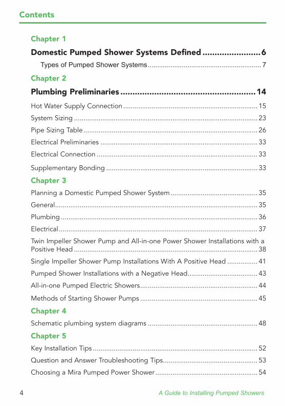
Domestic Pumped Shower Systems Defined ........................6Types of Pumped Shower Systems ............................................................ 7
Chapter 2
Plumbing Preliminaries ........................................................14
Hot Water Supply Connection ....................................................................... 15
System Sizing ................................................................................................. 23
Pipe Sizing Table ............................................................................................ 26
Electrical Preliminaries ................................................................................... 33
Electrical Connection ..................................................................................... 33
Supplementary Bonding ................................................................................ 33
Chapter 3
Planning a Domestic Pumped Shower System .............................................. 35
General ........................................................................................................... 35
Plumbing ........................................................................................................ 36
Electrical ......................................................................................................... 37
Twin Impeller Shower Pump and All-in-one Power Shower Installations with a Positive Head ................................................................................................. 38
Single Impeller Shower Pump Installations With A Positive Head ................ 41
Pumped Shower Installations with a Negative Head ..................................... 43
All-in-one Pumped Electric Showers .............................................................. 44
Methods of Starting Shower Pumps .............................................................. 45
Chapter 4
Schematic plumbing system diagrams .......................................................... 48
Chapter 5
Key Installation Tips ....................................................................................... 52
Question and Answer Troubleshooting Tips .................................................. 53
Choosing a Mira Pumped Power Shower ...................................................... 54

A Guide to Installing Pumped Showers 5
Chapter 6
Customer Support .......................................................................................... 55
After Sales Assistance .................................................................................... 55
Accessories ..................................................................................................... 56
KOHLER® Family of Businesses ..................................................................... 57
Contents
A Guide to Installing Pumped Showers6
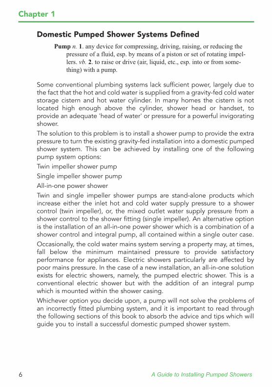
Domestic Pumped Shower Systems DefinedPump n. 1. any device for compressing, driving, raising, or reducing the
pressure of a fluid, esp. by means of a piston or set of rotating impel-lers. vb. 2. to raise or drive (air, liquid, etc., esp. into or from some-thing) with a pump.
Some conventional plumbing systems lack sufficient power, largely due to the fact that the hot and cold water is supplied from a gravity-fed cold water storage cistern and hot water cylinder. In many homes the cistern is not located high enough above the cylinder, shower head or handset, to provide an adequate 'head of water' or pressure for a powerful invigorating shower.The solution to this problem is to install a shower pump to provide the extra pressure to turn the existing gravity-fed installation into a domestic pumped shower system. This can be achieved by installing one of the following pump system options:Twin impeller shower pumpSingle impeller shower pumpAll-in-one power showerTwin and single impeller shower pumps are stand-alone products which increase either the inlet hot and cold water supply pressure to a shower control (twin impeller), or, the mixed outlet water supply pressure from a shower control to the shower fitting (single impeller). An alternative option is the installation of an all-in-one power shower which is a combination of a shower control and integral pump, all contained within a single outer case.Occasionally, the cold water mains system serving a property may, at times, fall below the minimum maintained pressure to provide satisfactory performance for appliances. Electric showers particularly are affected by poor mains pressure. In the case of a new installation, an all-in-one solution exists for electric showers, namely, the pumped electric shower. This is a conventional electric shower but with the addition of an integral pump which is mounted within the shower casing.Whichever option you decide upon, a pump will not solve the problems of an incorrectly fitted plumbing system, and it is important to read through the following sections of this book to absorb the advice and tips which will guide you to install a successful domestic pumped shower system.
Chapter 1
A Guide to Installing Pumped Showers 7
Chapter 1
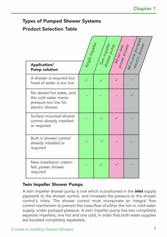
Types of Pumped Shower Systems
Product Selection Table
Surface mounted shower control already installed or required
Built in shower control already installed or required
No stored hot water, and the cold water mains pressure too low for electric shower
New installation cistern- fed, power shower required
A shower is required but head of water is too low
All-
ion-
one
pow
er s
how
erA
ll-in
-one
pum
ped
elec
tric
sho
wer
Application/ Pump solution
-
-
-
-
-
-
-
-Si
ngle
impe
ller
Twin Impeller Shower Pumps
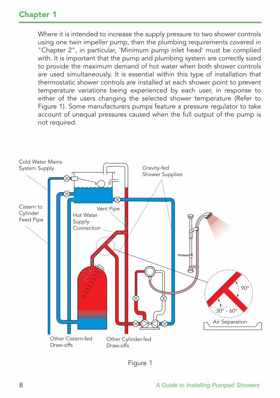
A twin impeller shower pump is one which is positioned in the inlet supply pipework to the shower control, and increases the pressure to the shower control's inlets. The shower control must incorporate an integral flow control mechanism to prevent the cross-flow of either the hot or cold water supply, under pumped pressure. A twin impeller pump has two completely separate impellers, one hot and one cold, in order that both water supplies are boosted completely separately.
-
Twin
impe
ller
show
er p
ump
-
A Guide to Installing Pumped Showers8
Chapter 1
Where it is intended to increase the supply pressure to two shower controls using one twin impeller pump, then the plumbing requirements covered in "Chapter 2", in particular, 'Minimum pump inlet head' must be complied with. It is important that the pump and plumbing system are correctly sized to provide the maximum demand of hot water when both shower controls are used simultaneously. It is essential within this type of installation that thermostatic shower controls are installed at each shower point to prevent temperature variations being experienced by each user, in response to either of the users changing the selected shower temperature (Refer to Figure 1). Some manufacturers pumps feature a pressure regulator to take account of unequal pressures caused when the full output of the pump is not required.
Cold Water Mains System Supply
Cistern to Cylinder Feed Pipe
Other Cistern-fed Draw-offs
Other Cylinder-fed Draw-offs
Vent PipeHot Water Supply Connection
Gravity-fed Shower Supplies
Figure 1
90°
30° - 60°
Air Separation
A Guide to Installing Pumped Showers 9
Single Impeller Shower Pumps
Chapter 1
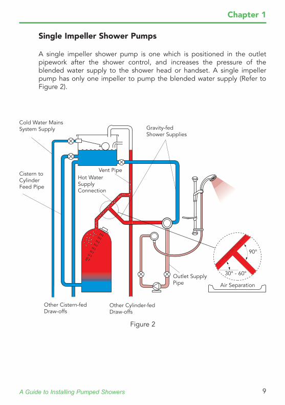
A single impeller shower pump is one which is positioned in the outlet pipework after the shower control, and increases the pressure of the blended water supply to the shower head or handset. A single impeller pump has only one impeller to pump the blended water supply (Refer to Figure 2).
Outlet Supply Pipe
Figure 2
Cold Water Mains System Supply
Cistern to Cylinder Feed Pipe
Other Cistern-fed Draw-offs
Other Cylinder-fed Draw-offs
Vent PipeHot Water Supply Connection
Gravity-fed Shower Supplies
90°
30° - 60°
Air Separation
A Guide to Installing Pumped Showers10
Chapter 1
Figure 3
Other Cistern-fed Draw-offs
Other Cylinder-fed Draw-offs
Cold Water Mains System Supply
Cistern to Cylinder Feed Pipe
Vent PipeHot Water Supply Connection
Gravity-fed Shower Supplies
All-In-one Power Showers
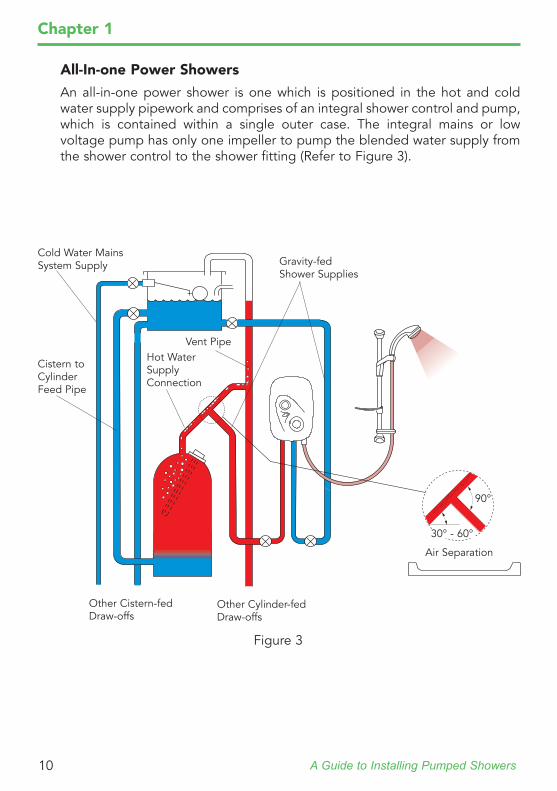
An all-in-one power shower is one which is positioned in the hot and cold water supply pipework and comprises of an integral shower control and pump, which is contained within a single outer case. The integral mains or low voltage pump has only one impeller to pump the blended water supply from the shower control to the shower fitting (Refer to Figure 3).
90°
30° - 60°
Air Separation
A Guide to Installing Pumped Showers 11
MIR
A DM
2 WIR
ELESS H
P/CO
MB
I1666.009N
85AM
AN
UFA
CTU
RED
KO
HLE
R M
IRA LTD
.C
HE
LTEN
HA
MG
L52 5EPTE
L: (+44) 0870 241 0888
ww
w.m
irashowers.com
HO
TC
OLD
POW
ER: 230 V A
C 20 W
PRO
TECTIO
N: IP24
MIN
. SUPPLY PR
ESSUR
E: 50 kPa (0.5 bar)M
AX. W
OR
KIN
G PR
ESSUR
E: 500 kPa (5 bar)M
AX. STATIC
PRESSU
RE: 1000 kPa (10 bar) (W
RA
S)M
AX. SU
PPLY WATER
TEMP: 65 °C
POSITIO
N A
PPLIAN
CE
OR
ISOLATE M
AIN
S ELECTR
ICITY B
EFOR
E R
EMO
VING
CO
VER!
F9001
DIG
ITAL M
IXER 2 W
IRELESS
MIRA DM2 WIRELESS LP (PUMPED)1666.009N85AMANUFACTURED
KOHLER MIRA LTD.CHELTENHAMGL52 5EPTEL: (+44) 0870 241 0888
www.mirashowers.com
HOT COLD
POWER: 230 V AC 20 WPROTECTION: IP24MIN. SUPPLY PRESSURE: 50 kPa (0.5 bar)MAX. WORKING PRESSURE: 500 kPa (5 bar)MAX. STATIC PRESSURE: 1000 kPa (10 bar) (WRAS)MAX. SUPPLY WATER TEMP: 65 °C
POSITION APPLIANCE OR
ISOLATE MAINS ELECTRICITY BEFORE REMOVING COVER!
F9001
DIGITAL MIXER 2 WIRELESS
Mira Platinum Shower Fittings
Pumped Digital Showers
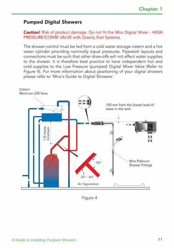
The shower control must be fed from a cold water storage cistern and a hot water cylinder providing nominally equal pressures. Pipework layouts and connections must be such that other draw-offs will not effect water supplies to the shower. It is therefore best practice to have independent hot and cold supplies to the Low Pressure (pumped) Digital Mixer Valve (Refer to Figure 4). For more information about positioning of your digital showers please refer to 'Mira's Guide to Digital Showers'.
1.0
met
re
min
imum
100 mm from the lowest level of water in the tank
Cistern Minimum 230 litres
90°
30° - 60°
Caution! Risk of product damage. Do not fit the Mira Digital Mixer - HIGH PRESSURE/COMBI VALVE with Gravity Fed Systems.
Air Separation
Figure 4
Chapter 1
A Guide to Installing Pumped Showers12
Chapter 1
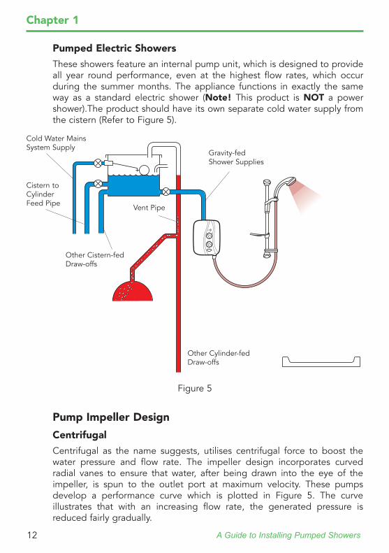
Pumped Electric Showers
These showers feature an internal pump unit, which is designed to provide all year round performance, even at the highest flow rates, which occur during the summer months. The appliance functions in exactly the same way as a standard electric shower (Note! This product is NOT a power shower).The product should have its own separate cold water supply from the cistern (Refer to Figure 5).
Pump Impeller Design
Centrifugal
Centrifugal as the name suggests, utilises centrifugal force to boost the water pressure and flow rate. The impeller design incorporates curved radial vanes to ensure that water, after being drawn into the eye of the impeller, is spun to the outlet port at maximum velocity. These pumps develop a performance curve which is plotted in Figure 5. The curve illustrates that with an increasing flow rate, the generated pressure is reduced fairly gradually.
Figure 5
Cold Water Mains System Supply
Cistern to Cylinder Feed Pipe
Other Cistern-fed Draw-offs
Other Cylinder-fed Draw-offs
Vent Pipe
Gravity-fed Shower Supplies
A Guide to Installing Pumped Showers 13
Chapter 1
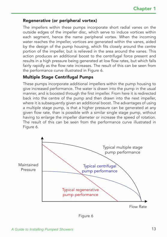
Typical multiple stage pump performance
Typical centrifugal pump performance
Typical regenerative pump performance
Regenerative (or peripheral vortex)
The impellers within these pumps incorporate short radial vanes on the outside edges of the impeller disc, which serve to induce vortices within each segment, hence the name peripheral vortex. When the incoming water reaches the impeller, vortices are generated within the vanes, aided by the design of the pump housing, which fits closely around the centre portion of the impeller, but is relieved in the area around the vanes. This action produces an additional boost to the centrifugal force present and results in a high pressure being generated at low flow rates, but which falls fairly rapidly as the flow rate increases. The result of this can be seen from the performance curve illustrated in Figure 6.
Multiple Stage Centrifugal Pumps
These pumps incorporate additional impellers within the pump housing to give increased performance. The water is drawn into the pump in the usual manner, and is boosted through the first impeller. From here it is redirected back into the centre of the pump and then drawn into the next impeller, where it is subsequently given an additional boost. The advantages of using a multiple stage pump, is that a higher pressure can be generated at any given flow rate, than is possible with a similar single stage pump, without having to enlarge the impeller diameter or increase the speed of rotation. The result of this can be seen from the performance curve illustrated in Figure 6.
Maintained Pressure
Flow Rate
Figure 6
A Guide to Installing Pumped Showers14
Chapter 2
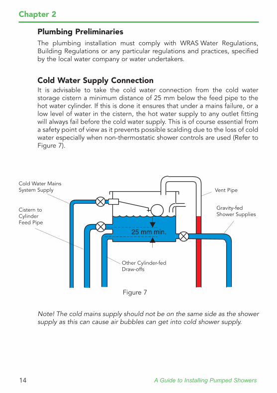
Plumbing PreliminariesThe plumbing installation must comply with WRAS Water Regulations, Building Regulations or any particular regulations and practices, specified by the local water company or water undertakers.
Cold Water Supply ConnectionIt is advisable to take the cold water connection from the cold water storage cistern a minimum distance of 25 mm below the feed pipe to the hot water cylinder. If this is done it ensures that under a mains failure, or a low level of water in the cistern, the hot water supply to any outlet fitting will always fail before the cold water supply. This is of course essential from a safety point of view as it prevents possible scalding due to the loss of cold water especially when non-thermostatic shower controls are used (Refer to Figure 7).
Figure 7
Cold Water Mains System Supply
Cistern to Cylinder Feed Pipe
Other Cylinder-fed Draw-offs
Vent Pipe
Gravity-fed Shower Supplies
Note! The cold mains supply should not be on the same side as the shower supply as this can cause air bubbles can get into cold shower supply.
A Guide to Installing Pumped Showers 15
Chapter 2
Hot Water Supply Connection
Air in water
The majority of problems involved with pumped installations are due to incorrectly designed or sized pipework, which results in air collecting in the plumbing system. However, even in a correctly designed and installed plumbing system, air is present. So how does it get there?The national water distribution system relies mainly on open air reservoirs as a means of storing water. Since the water is open to the atmosphere, wind and thermal currents cause air to be absorbed into solution, which results in high levels of air saturation. This saturation level will increase or decrease with the changing air temperatures and atmospheric pressures.From the reservoir the water is taken away under pressure in supply pipes. The water at this point contains air bubbles held in solution. However, the increase in pressure provided by the height of the reservoir and the reservoir pumps, causes the water to fall below its air saturation point, allowing potential for further absorption of air.Once this water is discharged into the cold water storage cistern it will be at atmospheric pressure and will be close to or above saturation point. Whilst stored in the cistern, any temperature rises will be minimal and as the pressure remains relatively constant, there will be little opportunity for the retained air to escape from the water. Water discharging into the cistern to replenish draw-offs will not only contain high levels of air, but will cause additional air to be taken up through entrainment of the discharge and turbulence of the water surface.From the cistern, some of this water will be fed under gravity pressure down to the hot water cylinder. When this water transfers from the cistern to the cyIinder, it is subjected to an increase in pressure, due to the distance between the cold water cistern and cylinder. This distance is known as 'head of water'. The increase in pressure will prevent any air escaping from the water, and in fact, it increases the potential for the absorption of more air. The effect of heating the water causes a reduction of the saturation point and the air is released from the water as air bubbles. The effect ofthe new pressure and temperature conditions classifies the water as super-saturated, or unable to absorb any more air.Friction and temperature gradients cause these air bubbles to collect on the walls of the cylinder. During the heating process, convection currents are set up inside the cylinder which circulate the water, until over a period of time, all the enclosed water has come into contact with the cylinder walls.
A Guide to Installing Pumped Showers16
Chapter 2
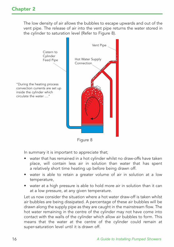
The low density of air allows the bubbles to escape upwards and out of the vent pipe. The release of air into the vent pipe returns the water stored in the cylinder to saturation level (Refer to Figure 8).
“During the heating process convection currents are set up inside the cylinder which circulate the water ....”
In summary it is important to appreciate that;• water that has remained in a hot cylinder whilst no draw-offs have taken
place, will contain less air in solution than water that has spent a relatively short time heating up before being drawn off.
• water is able to retain a greater volume of air in solution at a low temperature,
• water at a high pressure is able to hold more air in solution than it can at a low pressure, at any given temperature.
Let us now consider the situation where a hot water draw-off is taken whilst air bubbles are being dissipated. A percentage of these air bubbles will be drawn along the supply pipe as they are caught in the mainstream flow. The hot water remaining in the centre of the cylinder may not have come into contact with the walls of the cylinder which allow air bubbles to form. This means that the water at the centre of the cylinder could remain at super-saturation level until it is drawn off.
Figure 8
Hot Water Supply Connection
Cistern to Cylinder Feed Pipe
Vent Pipe
A Guide to Installing Pumped Showers 17
Chapter 2
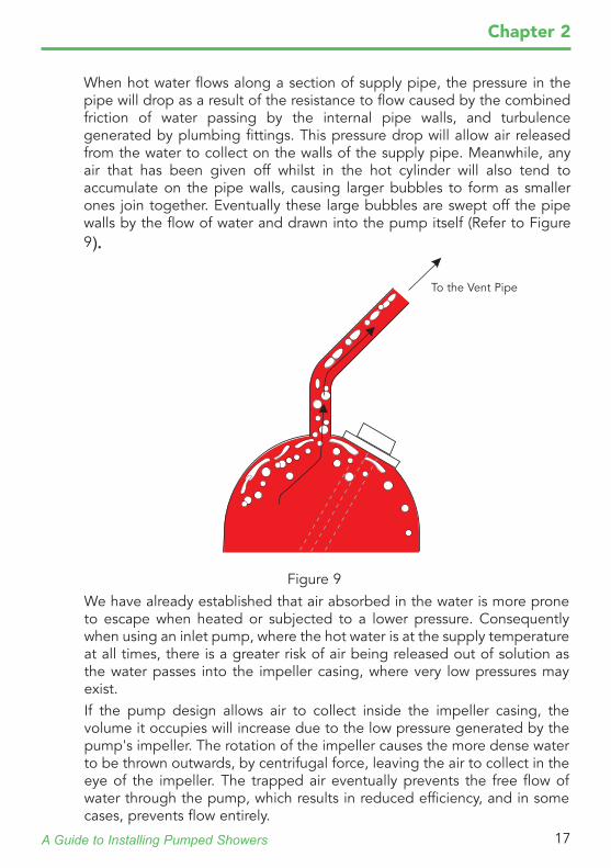
When hot water flows along a section of supply pipe, the pressure in the pipe will drop as a result of the resistance to flow caused by the combined friction of water passing by the internal pipe walls, and turbulence generated by plumbing fittings. This pressure drop will allow air released from the water to collect on the walls of the supply pipe. Meanwhile, any air that has been given off whilst in the hot cylinder will also tend to accumulate on the pipe walls, causing larger bubbles to form as smaller ones join together. Eventually these large bubbles are swept off the pipe walls by the flow of water and drawn into the pump itself (Refer to Figure 9).
To the Vent Pipe
We have already established that air absorbed in the water is more prone to escape when heated or subjected to a lower pressure. Consequently when using an inlet pump, where the hot water is at the supply temperature at all times, there is a greater risk of air being released out of solution as the water passes into the impeller casing, where very low pressures may exist.If the pump design allows air to collect inside the impeller casing, the volume it occupies will increase due to the low pressure generated by the pump's impeller. The rotation of the impeller causes the more dense water to be thrown outwards, by centrifugal force, leaving the air to collect in the eye of the impeller. The trapped air eventually prevents the free flow of water through the pump, which results in reduced efficiency, and in some cases, prevents flow entirely.
Figure 9
A Guide to Installing Pumped Showers18
Chapter 2
Assuming that the air which has been released from solution manages to travel through the pump, once it reaches the inlets of the shower control, the saturated air may upset the shower performance by inducing pressure or temperature fluctuations.In the previous paragraphs we have examined the 'natural' cause of air in water, but possibly one of the more common causes of air ingress into the pipework, or the pump, is where the hot feed to the pump is taken from too high up the vent pipe. This has the effect that when the pump is started, the suction generated by the pump is sufficient to draw the height of water above the vent pipe connection point, down the vent pipe. This allows air to be sucked through the now empty pipe, and into the pump. The problem can be avoided by making the connection to the vent pipe in the correct manner, as discussed in the later section on "Vent pipe connection".Another area which is worth mentioning is where pipe joints are not perfectly sound. This can lead to air being sucked into the plumbing system under the action of the pump. These instances can be avoided by following good plumbing practices throughout. One method of locating and isolating leaks would be to pressurise the system with air after each stage of the installation, and with the aid of a pressure gauge, check for any pressure leakage.
CavitationHaving looked at the effects of pressure and temperature on the air in water we need to expand this principle further to understand the problems of cavitation. The boiling point of water is 100oC at atmospheric pressure. However, as the pressure of the water is lowered the boiling point is also lowered. The normal temperature of stored hot water is approximately 65oC. If water, irrespective of temperature, is exposed to a sufficient pressure loss due to restrictive pipework, e.g. sharp bends, elbows or restrictive isolating valves, it is possible to induce the premature boiling of water inside of the supply pipe. The action of boiling causes the release of not only air out of solution, but the formation of water vapour or steam In fact the hotter the supply water temperature is, the less the drop in pressure needs to be to cause the water to boil.The premature boiling of water allows the release of steam vapour. These pockets of vapour travel through the restriction that caused the initial pressure drop, and in moving to an area of higher pressure, collapse or liquefy, and in so doing make a characteristic crackling/hissing noise. Some of the vapour will condense and be re-absorbed back into the water, but the majority will continue along the supply pipe as air, and end up entering the shower control.
A Guide to Installing Pumped Showers 19
Chapter 2
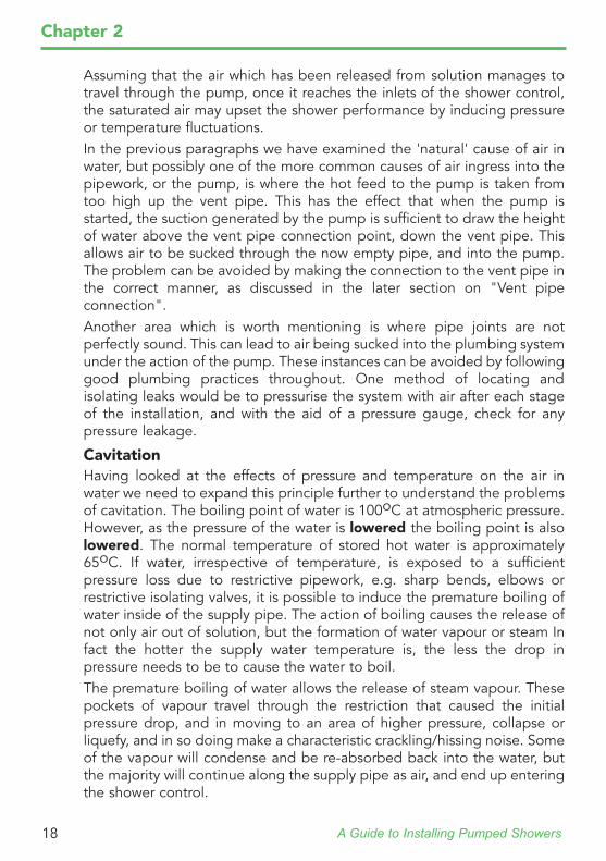
This problem is not merely confined to bends and fittings in the pipework. Often the pressure drop at the inlet of the pump itself is sufficient to induce cavitation which results in pockets of vapour collecting around the eye of the impeller in the pump. Steam vapour that collects in the impeller has the same effect as bubbles of air, which results in the reduced efficiency of the pump, and in some cases, entire flow prevention.The graph illustrates that water will boil at 100oC when exposed to atmospheric pressure, which is assumed to be 1 bar absolute pressure When water is exposed to a lower pressure of 0.57 bar, then the boiling point is lowered to a temperature of 85oC. (Refer to Figure 10).
The relevance of this can be appreciated when considering the practical situation of a pump generating a suction, or pressure drop of 0.6 bar, on pipework carrying hot water at 80oC. The initial pressure with the pump stationary can be taken as 1.0 bar absolute. Consequently, with the pump running and producing a suction of 0.6 bar, the pressure remaining in the pipework will be 0.4 bar. From the graph it can be seen that water at 80oC. will actually boil at 0.47 bar, which means that a pump in this situation will suffer from cavitation.
Boiling Point of Water at Varying Pressures
Temperature (oC)
Ab
solu
te p
ress
ure
(bar
)
1.0
0.7
0.6
0.5
0
0.1
0.2
0.3
0.4
0.9
0.8
10 20 30 40 50 60 70 80 90 1000
KEY
Water
Steam
Figure 10
A Guide to Installing Pumped Showers20
Chapter 2
However, if the hot water was stored at a more usual level of 60 oC, by referring to the graph it can be seen that the pump will not suffer from cavitation until a pressure drop of 0.25 bar is reached.It is important to appreciate that although this graph gives an indication of the boiling point of water, where the water supply is super-saturated, and a low pressure area is encountered, it will induce air release from the water, which although is not true cavitation, may result in the same symptoms of reduced efficiency or lack of flow.
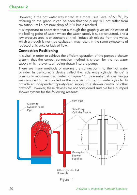
Connection PositioningIt is vital, in order to achieve the efficient operation of the pumped shower system, that the correct connection method is chosen for the hot water supply which prevents air being drawn into the pump.There are many methods of making the connection into the hot water cylinder. In particular, a device called the 'side entry cylinder flange' is commonly recommended (Refer to Figure 11). Side entry cylinder flanges are designed to be installed in the side wall of the hot water cylinder to provide an independent gravity-feed supply to a shower control or other draw-off. However, these devices are not considered suitable for a pumped shower system for the following reasons:
Cistern to Cylinder Feed Pipe
Other Cylinder-fed Draw-offs
Vent Pipe
Gravity-fed Shower Supplies
Side Entry Cylinder Flange
Figure 11
A Guide to Installing Pumped Showers 21
Chapter 2
A side entry cylinder flange connection does not allow the efficient separation of air bubbles from the water as it is being drawn off.Inadequate pipe sizing could allow the demand from the pump to exceed the cistern's ability to supply the cylinder. The water contained in the vent pipe, and the volume of water above the side entry cylinder flange will be drawn off, leaving the elements of a top entry immersion heater exposed. Under these conditions, operation of the immersion heater would lead to overheating and the failure of the elements.Should the cold water mains system supply fail, the pump can continue to draw hot water until the volume of water above the side entry cylinder flange has been drawn off. If installed with a non-thermostatic shower control the user could be subjected to hot water at the cylinder storage temperature.Drawing water from the side entry cylinder flange means that the volume of water above the flange is not available for showering. This effectively reduces, by a third, the volume of water available for use. The flange will only draw-off heated water below the connection point. When heated, the hot water 'floats' on top of the cold water at the bottom of the cylinder. When hot water is drawn off, it is replaced by cold water at the bottom of the cylinder, which effectively traps the hot water above the connection point.Operation of the pump will cause vibration which will be directly transmitted to the cylinder through the side entry cylinder flange. The vibration may dislodge air collected on the cylinder walls, which could be drawn through the side entry cylinder flange, and into the hot supply to the pump.The following section recommends a solution which is not only cost effective but more efficient at separating air from water.
Vent Pipe Connection
The previous sub-sections of 'Hot water supply connection' have examined the fact that air occurs naturally in water, and when heated, or subjected to low pressures, the water will allow absorbed air to be released into mainstream flow. To minimise the level of air in water, and its effect on a pumped shower system's performance, it is important to design an efficient method of allowing air to escape from the hot water cylinder.The first step is ensure that air bubbles can flow freely up the vent pipe. To achieve this the vent pipe must be of an adequate size to prevent the complete cross-sectional area being occupied by the escaping air (Refer to Figure 12).
A Guide to Installing Pumped Showers22
Chapter 2
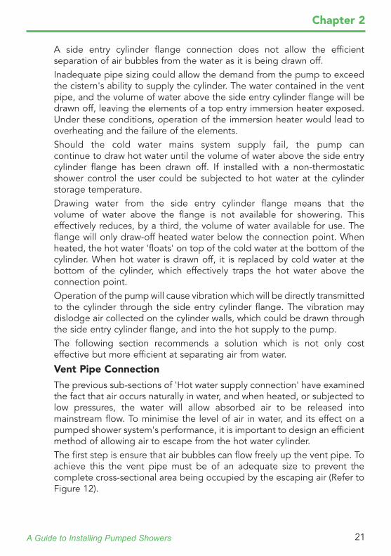
If the vent pipe is inadequately sized the surface tension of the bubbles will create a bottleneck effect and impede the free escape of the air.
Hot Water Supply Connection
Inadequately sized vent pipe with air bubbles unable to escape freely
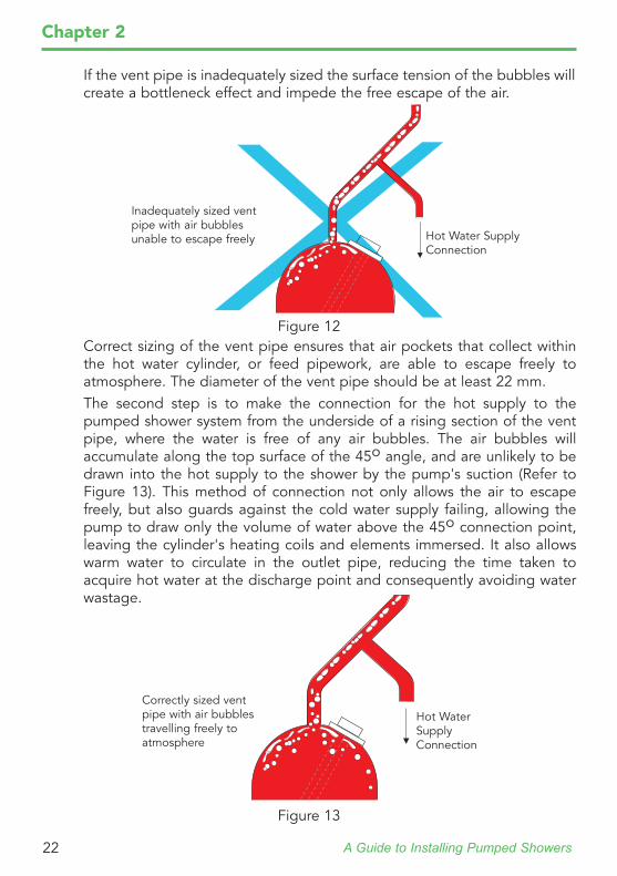
Correct sizing of the vent pipe ensures that air pockets that collect within the hot water cylinder, or feed pipework, are able to escape freely to atmosphere. The diameter of the vent pipe should be at least 22 mm.The second step is to make the connection for the hot supply to the pumped shower system from the underside of a rising section of the vent pipe, where the water is free of any air bubbles. The air bubbles will accumulate along the top surface of the 45o angle, and are unlikely to be drawn into the hot supply to the shower by the pump's suction (Refer to Figure 13). This method of connection not only allows the air to escape freely, but also guards against the cold water supply failing, allowing the pump to draw only the volume of water above the 45o connection point, leaving the cylinder's heating coils and elements immersed. It also allows warm water to circulate in the outlet pipe, reducing the time taken to acquire hot water at the discharge point and consequently avoiding water wastage.
Hot Water Supply Connection
Correctly sized vent pipe with air bubbles travelling freely to atmosphere
Figure 12
Figure 13
A Guide to Installing Pumped Showers 23
Chapter 2
System SizingThe majority of problems involved with pumped installations are due to incorrectly designed or sized pipework. Prior to installing a pumped shower system, it is prudent to undertake some preliminary calculations to assess whether the plumbing system is capable of supplying the demand placed on it by the pump. The following section provides important step by step procedure, to calculate the plumbing system's suitability to meet these new demands.
Step 1
Installing a pump into an existing plumbing system will place additional demands on the system due to the increased flow rate of water. If the supply pipework cannot handle the increased flow rate then;• the expected flow performance of the pumped shower system will be
compromised.• air may be drawn into the hot supply from the vent pipe, causing a
reduced efficiency of the pump, and in some cases preventing flow entirely.
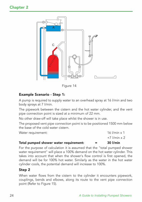
To assess whether air will be drawn into the vent pipe, it is possible to estimate the extent to which the level of water will fall in the vent pipe. This is achieved by calculating the pressure loss due to friction, between the cistern and the proposed hot take off point from the vent pipe, when flow is taking place. This will determine the final position of the connection point for the hot supply to the pump.To calculate the pressure loss whilst flow is taking place, an assessment of the maximum flow rate through the pipework between points 'A' and 'C' must be made. (Refer to Figure 14) The manufacturer of the shower control and shower fittings will be able to provide the flow rate against pressure loss characteristics for their products.Any simultaneous hot water draw-offs that are likely to be made whilst the pumped shower is in use must be taken into account when establishing the maximum flow rate.
A Guide to Installing Pumped Showers24
Chapter 2
Example Scenario - Step 1:
A pump is required to supply water to an overhead spray at 16 l/min and two body sprays at 7 l/min.The pipework between the cistern and the hot water cylinder, and the vent pipe connection point is sized at a minimum of 22 mm.No other draw-off will take place whilst the shower is in use.The proposed vent pipe connection point is to be positioned 1500 mm below the base of the cold water cistern.Water requirement: 16 l/min x 1 +7 l/min x 2Total pumped shower water requirement: = 30 l/minFor the purpose of calculation it is assumed that the "total pumped shower water requirement" will place a 100% demand on the hot water cylinder. This takes into account that when the shower's flow control is first opened, the demand will be for 100% hot water. Similarly as the water in the hot water cylinder cools, the potential demand will increase to 100%.
Step 2
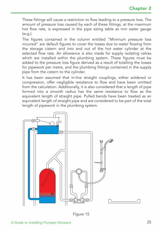
When water flows from the cistern to the cylinder it encounters pipework, couplings, bends and elbows, along its route to the vent pipe connection point (Refer to Figure 15).
A
C
Figure 14
A Guide to Installing Pumped Showers 25
Chapter 2
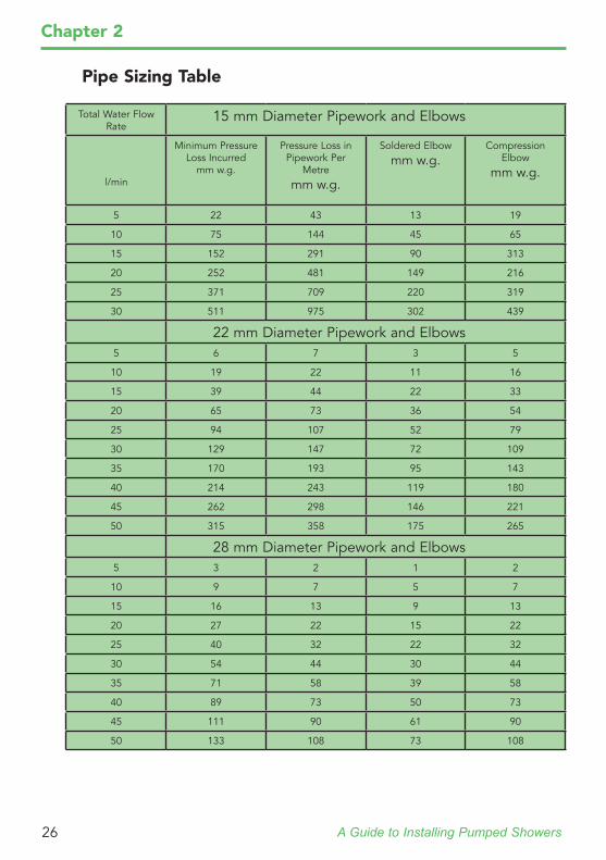
These fittings will cause a restriction to flow leading to a pressure loss. The amount of pressure loss caused by each of these fittings, at the maximum hot flow rate, is expressed in the pipe sizing table as mm water gauge (w.g.).The figures contained in the column entitled "Minimum pressure loss incurred" are default figures to cover the losses due to water flowing from the storage cistern and into and out of the hot water cylinder at the selected flow rate. An allowance is also made for supply isolating valves which are installed within the plumbing system. These figures must be added to the pressure loss figure derived as a result of totalling the losses for pipework per metre, and the plumbing fittings contained in the supply pipe from the cistern to the cylinder.It has been assumed that in-line straight couplings, either soldered or compression, offer negligible resistance to flow and have been omitted from the calculation. Additionally, it is also considered that a length of pipe formed into a smooth radius has the same resistance to flow as the equivalent length of straight pipe. Pulled bends have been treated as an equivalent length of straight pipe and are considered to be part of the total length of pipework in the plumbing system.
B
A
Figure 15
A Guide to Installing Pumped Showers26
Chapter 2
Pipe Sizing Table
Total Water Flow Rate
15 mm Diameter Pipework and Elbows
l/min
Minimum Pressure Loss Incurred
mm w.g.
Pressure Loss in Pipework Per
Metre
mm w.g.
Soldered Elbow
mm w.g.Compression
Elbow
mm w.g.
5 22 43 13 19
10 75 144 45 65
15 152 291 90 313
20 252 481 149 216
25 371 709 220 319
30 511 975 302 439
22 mm Diameter Pipework and Elbows5 6 7 3 5
10 19 22 11 16
15 39 44 22 33
20 65 73 36 54
25 94 107 52 79
30 129 147 72 109
35 170 193 95 143
40 214 243 119 180
45 262 298 146 221
50 315 358 175 265
28 mm Diameter Pipework and Elbows5 3 2 1 2
10 9 7 5 7
15 16 13 9 13
20 27 22 15 22
25 40 32 22 32
30 54 44 30 44
35 71 58 39 58
40 89 73 50 73
45 111 90 61 90
50 133 108 73 108
A Guide to Installing Pumped Showers 27
Chapter 2
Example Scenario - Step 2:
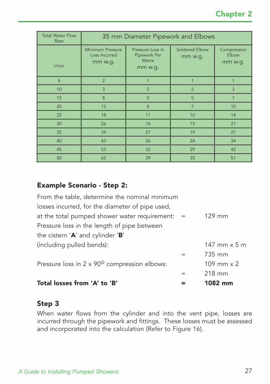
From the table, determine the nominal minimumlosses incurred, for the diameter of pipe used,at the total pumped shower water requirement: = 129 mmPressure loss in the length of pipe betweenthe cistern ‘A’ and cylinder ‘B’(including pulled bends): 147 mm x 5 m = 735 mmPressure loss in 2 x 90o compression elbows: 109 mm x 2 = 218 mmTotal losses from ‘A’ to ‘B’ = 1082 mm
Step 3When water flows from the cylinder and into the vent pipe, losses are incurred through the pipework and fittings. These losses must be assessed and incorporated into the calculation (Refer to Figure 16).
Total Water Flow Rate
35 mm Diameter Pipework and Elbows
l/min
Minimum Pressure Loss Incurred
mm w.g.
Pressure Loss in Pipework Per
Metre
mm w.g.
Soldered Elbow
mm w.g.Compression
Elbow
mm w.g.
5 2 1 1 1
10 3 2 2 3
15 8 5 5 7
20 13 8 7 10
25 18 11 10 14
30 26 16 15 21
35 34 21 19 27
40 43 26 24 34
45 53 32 29 42
50 65 39 35 51
A Guide to Installing Pumped Showers28
Chapter 2
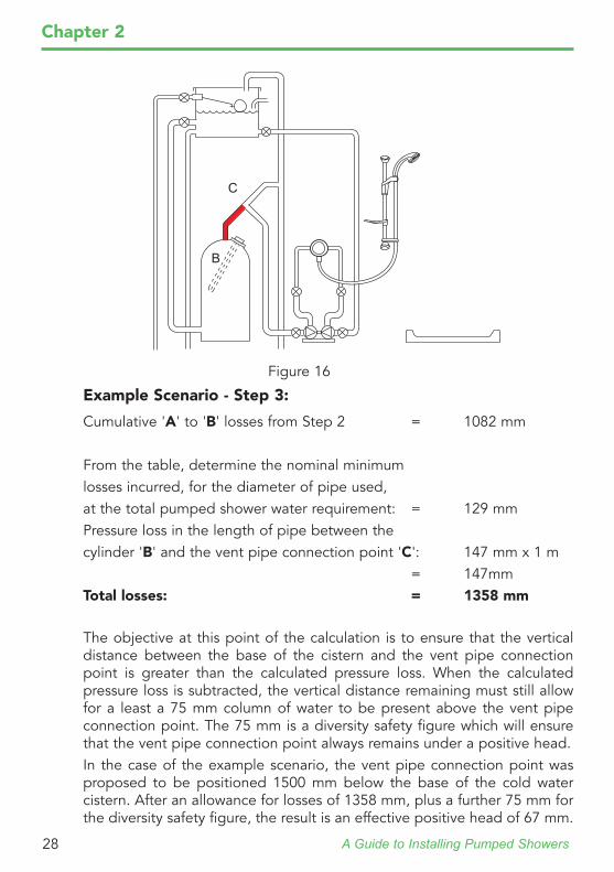
Example Scenario - Step 3:
Cumulative 'A' to 'B' losses from Step 2 = 1082 mm
From the table, determine the nominal minimumlosses incurred, for the diameter of pipe used,at the total pumped shower water requirement: = 129 mmPressure loss in the length of pipe between thecylinder 'B' and the vent pipe connection point 'C': 147 mm x 1 m = 147mmTotal losses: = 1358 mm
The objective at this point of the calculation is to ensure that the vertical distance between the base of the cistern and the vent pipe connection point is greater than the calculated pressure loss. When the calculated pressure loss is subtracted, the vertical distance remaining must still allow for a least a 75 mm column of water to be present above the vent pipe connection point. The 75 mm is a diversity safety figure which will ensure that the vent pipe connection point always remains under a positive head.In the case of the example scenario, the vent pipe connection point was proposed to be positioned 1500 mm below the base of the cold water cistern. After an allowance for losses of 1358 mm, plus a further 75 mm for the diversity safety figure, the result is an effective positive head of 67 mm.
C
B
Figure 16
A Guide to Installing Pumped Showers 29
Chapter 2
Therefore, with a pumped shower flow rate of 30 l/m, air will not be drawn into the hot supply to the pump.In borderline cases where it is physically impossible to achieve the desired vent pipe connection point, the level of water in the cistern can be taken as a datum point, instead of the base of the cistern. However, it is important to ensure that the vertical dimension is taken from where a maintained water level is achieved. This should allow for a situation where the maximum draw-offs of hot and cold water are taking place, and the level in the cistern is no longer dropping, when being replenished by the cold water mains system.If the calculated vent pipe connection point is still not physically achievable, then the supply pipework size must be increased to reduce the effective pressure loss.
Step 4
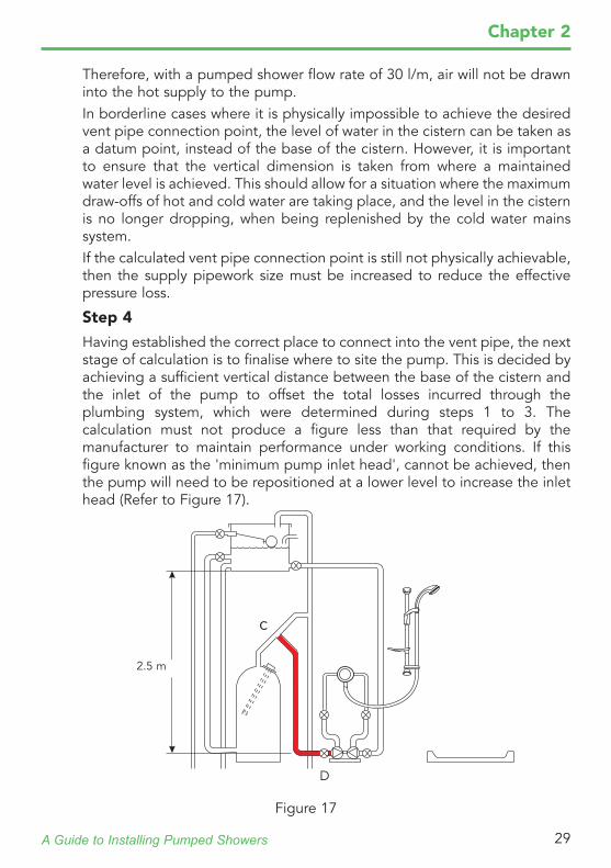
Having established the correct place to connect into the vent pipe, the next stage of calculation is to finalise where to site the pump. This is decided by achieving a sufficient vertical distance between the base of the cistern and the inlet of the pump to offset the total losses incurred through the plumbing system, which were determined during steps 1 to 3. The calculation must not produce a figure less than that required by the manufacturer to maintain performance under working conditions. If this figure known as the 'minimum pump inlet head', cannot be achieved, then the pump will need to be repositioned at a lower level to increase the inlet head (Refer to Figure 17).
D
c
2.5 m
Figure 17
A Guide to Installing Pumped Showers30
Chapter 2
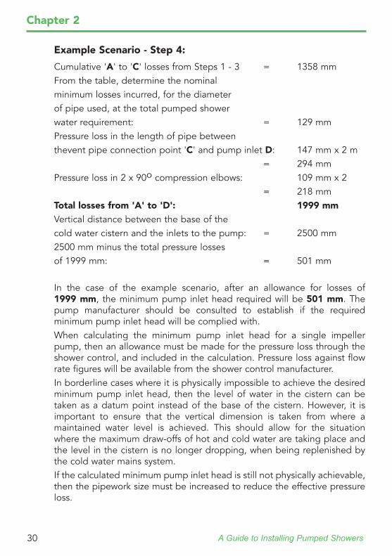
Example Scenario - Step 4:
Cumulative 'A' to 'C' losses from Steps 1 - 3 = 1358 mmFrom the table, determine the nominalminimum losses incurred, for the diameterof pipe used, at the total pumped showerwater requirement: = 129 mm Pressure loss in the length of pipe betweenthevent pipe connection point 'C' and pump inlet D: 147 mm x 2 m = 294 mmPressure loss in 2 x 90o compression elbows: 109 mm x 2 = 218 mmTotal losses from 'A' to 'D': 1999 mmVertical distance between the base of thecold water cistern and the inlets to the pump: = 2500 mm2500 mm minus the total pressure lossesof 1999 mm: = 501 mm
In the case of the example scenario, after an allowance for losses of 1999 mm, the minimum pump inlet head required will be 501 mm. The pump manufacturer should be consulted to establish if the required minimum pump inlet head will be complied with.When calculating the minimum pump inlet head for a single impeller pump, then an allowance must be made for the pressure loss through the shower control, and included in the calculation. Pressure loss against flow rate figures will be available from the shower control manufacturer.In borderline cases where it is physically impossible to achieve the desired minimum pump inlet head, then the level of water in the cistern can be taken as a datum point instead of the base of the cistern. However, it is important to ensure that the vertical dimension is taken from where a maintained water level is achieved. This should allow for the situation where the maximum draw-offs of hot and cold water are taking place and the level in the cistern is no longer dropping, when being replenished by the cold water mains system.If the calculated minimum pump inlet head is still not physically achievable, then the pipework size must be increased to reduce the effective pressure loss.
A Guide to Installing Pumped Showers 31
Chapter 2
Step 5
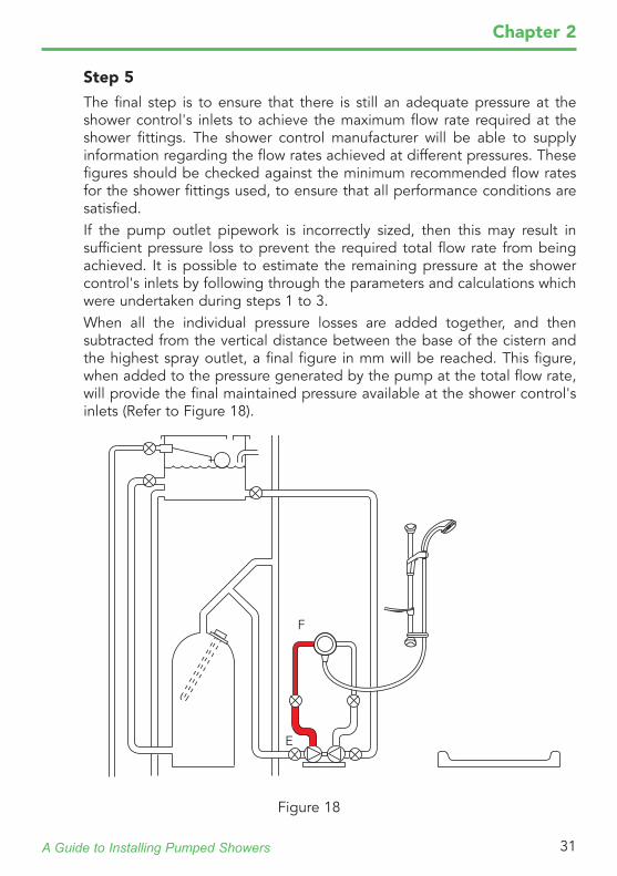
The final step is to ensure that there is still an adequate pressure at the shower control's inlets to achieve the maximum flow rate required at the shower fittings. The shower control manufacturer will be able to supply information regarding the flow rates achieved at different pressures. These figures should be checked against the minimum recommended flow rates for the shower fittings used, to ensure that all performance conditions are satisfied.If the pump outlet pipework is incorrectly sized, then this may result in sufficient pressure loss to prevent the required total flow rate from being achieved. It is possible to estimate the remaining pressure at the shower control's inlets by following through the parameters and calculations which were undertaken during steps 1 to 3.When all the individual pressure losses are added together, and then subtracted from the vertical distance between the base of the cistern and the highest spray outlet, a final figure in mm will be reached. This figure, when added to the pressure generated by the pump at the total flow rate, will provide the final maintained pressure available at the shower control's inlets (Refer to Figure 18).
F
E
Figure 18
A Guide to Installing Pumped Showers32
Chapter 2
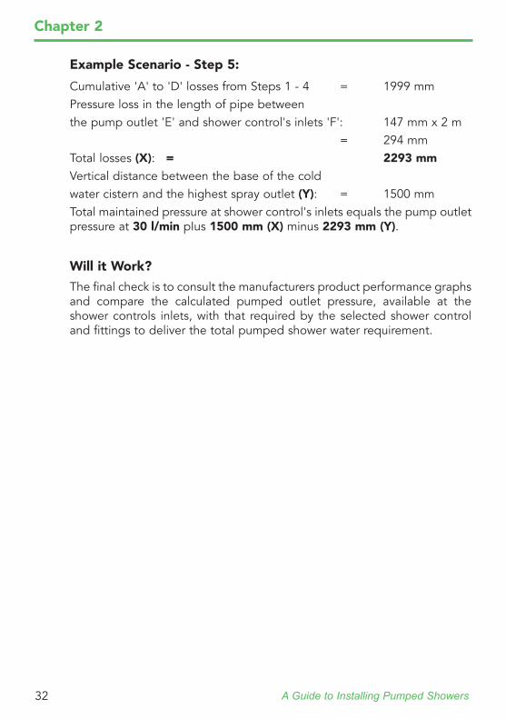
Example Scenario - Step 5:
Cumulative 'A' to 'D' losses from Steps 1 - 4 = 1999 mm Pressure loss in the length of pipe betweenthe pump outlet 'E' and shower control's inlets 'F': 147 mm x 2 m = 294 mmTotal losses (X): = 2293 mmVertical distance between the base of the coldwater cistern and the highest spray outlet (Y): = 1500 mmTotal maintained pressure at shower control's inlets equals the pump outlet pressure at 30 l/min pIus 1500 mm (X) minus 2293 mm (Y).
Will it Work?
The final check is to consult the manufacturers product performance graphs and compare the calculated pumped outlet pressure, available at the shower controls inlets, with that required by the selected shower control and fittings to deliver the total pumped shower water requirement.
A Guide to Installing Pumped Showers 33
Chapter 2
Electrical PreliminariesThe electrical installation must comply with "Requirements for Electrical Installations" (refer to Section 7) commonly referred to as the lEE Wiring Regulations, or any particular regulations and practices, specified by the local electricity supply company. If required, the installation could be carried out by an electrician or contractor who is registered, or is a member of, an association such as:• National Inspection Council for Electrical Installation and Contracting
(NICEIC), throughout the UK.• The Electrical Contractors Association (ECA), England and Wales.• The Electrical Contractors Association of Scotland (ECAS).
Electrical ConnectionThe electrical mains supply for the pump should be permanently connected to the fixed electrical wiring of the mains system, via a switched 5 Amp fused connection unit, or equivalent with a contact separation across each pole of a least 3 mm. The connection unit must be positioned so that it is inaccessible to any person using the shower. The inclusion of a Residual Current Device (RCD) with a trip current of 30 mA is recommended. This may already be part of the consumer unit.Where a momentary action pull-cord switch is installed to provide semi-automatic operation of the pump, then the proximity of the switch should be in line with the requirements of BS 7671. The cord of the switch should be placed so that it is within reach of the shower enclosure.
Supplementary Bonding
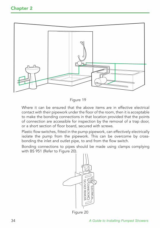
When a pumped shower is installed as part of a new plumbing system, then it must be correctly earth bonded to other conductive items, immediately accessible in the vicinity. Local supplementary bonding cables of at least 4 mm2 csa (cross sectional area), are required, if the electrical circuit does not have any form of mechanical protection. If the circuit is mechanically protected then 2.5 mm2 cable can be used. It is essential that all simultaneously exposed conductive parts of electrical equipment and extraneous conductive parts, that are likely to introduce an earth potential, are earth bonded (Refer to Figure 19).
Extraneous conductive parts may include the following:Metal baths, taps, exposed metal pipes for hot or cold water, exposed metal waste pipes, centrally heated radiators, towel rails and exposed central heating pipework.
A Guide to Installing Pumped Showers34
Chapter 2
Where it can be ensured that the above items are in effective electrical contact with their pipework under the floor of the room, then it is acceptable to make the bonding connections in that location provided that the points of connection are accessible for inspection by the removal of a trap door, or a short section of floor board, secured with screws.Plastic flow switches, fitted in the pump pipework, can effectively electrically isolate the pump from the pipework. This can be overcome by cross-bonding the inlet and outlet pipe, to and from the flow switch. Bonding connections to pipes should be made using clamps complying with BS 951 (Refer to Figure 20).
Figure 19
Figure 20
A Guide to Installing Pumped Showers 35
Chapter 3
Planning a Domestic Pumped Shower SystemThe following section provides advice on practical issues concerned with the pre- installation of a pumped shower system.
General
1. Do not take risks with plumbing or electrical equipment, take time to read through the manufacturers Installation, Operation and Maintenance Guide, supplied with each product. Follow all warnings, cautions contained in the guide, or on the product. If you are still unsure of any of the procedures, contact the manufacturer, or, seek the services of a professional installation contractor. Refer to Chapter 2 and the relevant sections; "Introduction - Plumbing" or "Introduction - Electrical" for further advice.
2. Isolate electrical and water supplies before proceeding with the installation.
3. Do not install any of the products in a position where they could become frozen.
4. The hot and cold water supplies for a pumped shower system must originate from cold water cistern and a cistern-fed, vented hot water cylinder and provide nominally equal pressures.
5. In solid wall installations the supply pipework should be installed within ducting, to allow some free lateral movement when making supply connections, and to ensure compliance with the requirements of water regulations "Accessibility of pipes and pipe fittings".
6. Pumps, in line with all mechanical devices, generate noise whilst operating. The amount of noise will vary depending on the design of the pump. Mounting the pump on rubber isolation mounts, or material of high density, will reduce the transmitted sound levels. he type of wall structure will affect perceived sound levels, for example, a solid wall will provide quieter operation than stud partition wall.
7. If the pump motor is air cooled it is important that the flow of air is not impeded around the product.
8. To comply with BS 6700 the hot water storage temperature should not exceed 60 oC. Operation at this temperature will reduce the rate of limescale formation in the system and potential pump cavitation.
A Guide to Installing Pumped Showers36
Chapter 3
Plumbing
1. Installations must comply with the water regulations or local water undertakers regulations.
2. The cold water storage cistern should have a minimum storage capacity of 230 litres to provide adequate showering time and to comply with the requirements of BS EN 806.
3. The installation of a pump will place a large demand on the resource of the plumbing system. Ensure that the plumbing system is correctly sized and modified if necessary. Refer to Chapter 2 "System sizing" for further advice.
4. Side entry cylinder flanges are not recommended for the source of hot water supply to a pumped shower system. Refer to Chapter 2 "Hot Water supply connection" for further advice.
5. The routing of high level pipework should be avoided as air locking may result. High level pipework on the outlet side of the pump can be purged of air by installing float-type automatic air vents at the highest point along the pipe run before the pipe descends.
6. Supply pipework must be flushed clear of debris before connecting any products.
7. Conveniently situated isolating valves should be fitted in the plumbing system for servicing purposes.
8. Pumps can develop leaks and should, therefore, not be situated where seepage may go undetected and cause damage.
9. The pump must be installed such that it is accessible for servicing or removal. When servicing or disconnecting, small amounts of water may drain from the pump and pipework.
10.Protect adjacent products from the effects of direct heat transfer and solder fluxes whilst making soldered connections, as damage could result to the pump and plastic components.
11.Pumps that are provided with flexible inlet and outlet connection pipes, must not be bent through more than a small angle (typically 30o either side of vertical), and should not be stressed by the pipework geometry. The flexible pipes are provided to reduce the sound being transmitted into the pipework and are not intended to replace plumbing elbows or pulled bends.
A Guide to Installing Pumped Showers 37
Chapter 3
Electrical
1. The electrical installation must comply with "Requirements for Electrical Installations" (refer to Section 7) commonly referred to as the lEE Wiring Regulations, or any particular regulations and practices, specified by the local electricity supply company.
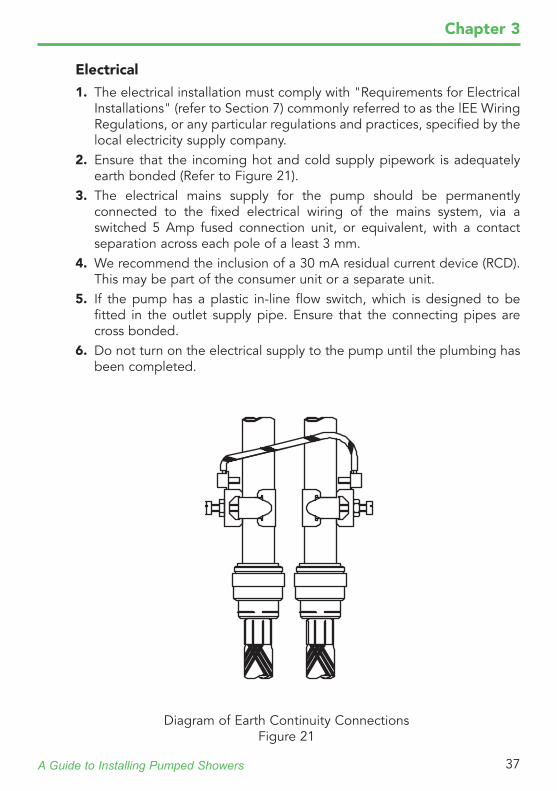
2. Ensure that the incoming hot and cold supply pipework is adequately earth bonded (Refer to Figure 21).
3. The electrical mains supply for the pump should be permanently connected to the fixed electrical wiring of the mains system, via a switched 5 Amp fused connection unit, or equivalent, with a contact separation across each pole of a least 3 mm.
4. We recommend the inclusion of a 30 mA residual current device (RCD). This may be part of the consumer unit or a separate unit.
5. If the pump has a plastic in-line flow switch, which is designed to be fitted in the outlet supply pipe. Ensure that the connecting pipes are cross bonded.
6. Do not turn on the electrical supply to the pump until the plumbing has been completed.
Diagram of Earth Continuity ConnectionsFigure 21
A Guide to Installing Pumped Showers38
Chapter 3
Twin Impeller Shower Pump and All-in-one Power Shower Installations with a Positive Head
Note! To reduce repetition, an "all-in-one power shower" is referred to as a "all-in-one".
1. All pipework must be sized to control the pressure loss in the system. It is important that the cumulative pressure losses through the plumbing system pipework do not cause air to be drawn into the supply pipe to the pump or all-in-one, or that the manufacturers minimum pump inlet cannot be achieved. Refer to Chapter 2 "System sizing" for further advice
2. For a single shower the cold feed pipe to the cylinder must be at least 22 mm diameter. It is important that the hot water being drawn off from the cylinder can be readily replenished by the cistern. The feed pipe from the cistern to the cylinder must be sized such that the pressure losses through the feed pipe do not cause air to be drawn into the pump or all-in-one. Refer to Chapter 2 "System sizing" for further advice.
3. The vent pipe needs to be at least 22 mm in diameter. Correct sizing of the vent pipe ensures that air pockets dissipated within the hot water cylinder or feed pipework are able to escape freely without a reduction in speed, or creating a backlog. Refer to Chapter 2 "Hot water supply connection" for further advice.
4. The hot water supply pipe to the pump or all-in-one must be taken from the vent pipe connection point at the minimum distance below the cold water cistern. This minimum distance must be complied with to ensure that under operating conditions it is not possible to draw down the height of water above the vent pipe connection point, causing air to be sucked into the now empty vent pipe and through to the pump or all-in-one. Refer to Chapter 2 "Hot water supply connection" for further advice.
5. The hot water supply pipe to the pump or all-in-one must be correctly connected to ensure the proper separation of air bubbles venting from the cylinder. Air bubbles that are given off from the hot water and float up through the cylinder and into the vent pipe will accumulate on the upper surface of the angled section of pipe, before proceeding to travel to atmosphere. By connecting from the underside of this section of pipe, water drawn into the pump or all-in-one, will be substantially free of the air bubbles. Refer to Chapter 2 "Hot water supply connection" for further advice.
A Guide to Installing Pumped Showers 39
Chapter 3
6. The minimum pump inlet head must be ensured at all times. It is important to the efficiency of a pump that it is located such that there is sufficient positive head onto the pump itself to maintain performance under working conditions. The minimum pump inlet head will be quoted by the manufacturer and must be complied with to ensure that the declared performance is achieved. Refer to Chapter 2 "System sizing" for further advice.
7. The hot and cold supply pipes to the pump or all-in-one should fall continuously. If pipework is installed such that it rises and falls prior to reaching the pump or all-in-one there is a risk of air pockets accumulating at any high points. The air will result in a reduced flow rate and result in an effective pipe blockage, or a complete air-lock. Float-type automatic air vents cannot be installed prior to a pump or all-in-one to~remove this air as the pipe pressure may fall below atmospheric pressure allowing air to be drawn through the air vent. It is important that the pipework falls continuously to the pump, or all-in-one to eliminate the risk.
8. The cold feed to the pump or all-in-one should not be used to supply any other outlet. In order to prevent any pressure fluctuations in the cold supply to the pump or all-in-one, an independent, correctly sized supply pipe should be taken from the cold water storage cistern. Outlet fittings supplied by the same pipe will cause pressure fluctuations which will affect the pump or all-in-ones performance.
9. Pipe runs should be as short as possible to avoid excessive dead legs. Long lengths of pipe from the hot cylinder to the all-in-one or shower control should be avoided as the water in the pipe will cool during periods of no-flow. This volume of water will have to be drawn off before water at the correct temperature is available for showering. This is not only wasteful but the long lengths of pipe cause a pressure loss which allows the release of air from water.
10.The spray head must be positioned at a minimum distance below the cistern to provide an adequate flow rate to ensure flow switch operation. (Pumps fitted with flow switches only) When the shower is initially opened, a small amount of flow will take place due to gravity. Once this reaches the minimum level required to activate the flow switch, the electric circuit to the pump will cause the pump to start. The minimum distance, between the base of the cistern and the shower fitting, required to start the pump will be specified by the manufacturer. Refer to Chapter 3 "Methods of starting shower pumps" for further advice.
A Guide to Installing Pumped Showers40
Chapter 3
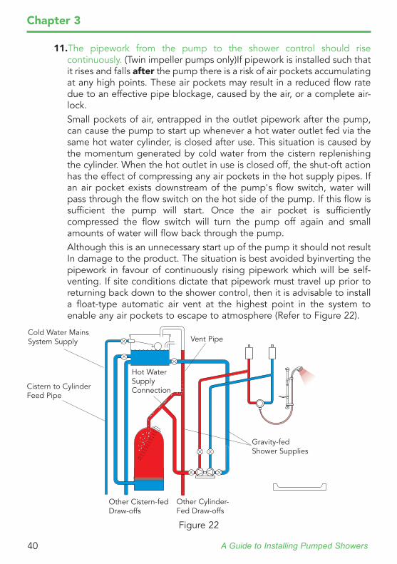
11.The pipework from the pump to the shower control should rise continuously. (Twin impeller pumps only)If pipework is installed such that it rises and falls after the pump there is a risk of air pockets accumulating at any high points. These air pockets may result in a reduced flow rate due to an effective pipe blockage, caused by the air, or a complete air-lock.
Small pockets of air, entrapped in the outlet pipework after the pump, can cause the pump to start up whenever a hot water outlet fed via the same hot water cylinder, is closed after use. This situation is caused by the momentum generated by cold water from the cistern replenishing the cylinder. When the hot outlet in use is closed off, the shut-oft action has the effect of compressing any air pockets in the hot supply pipes. If an air pocket exists downstream of the pump's flow switch, water will pass through the flow switch on the hot side of the pump. If this flow is sufficient the pump will start. Once the air pocket is sufficiently compressed the flow switch will turn the pump off again and small amounts of water will flow back through the pump.
Although this is an unnecessary start up of the pump it should not result In damage to the product. The situation is best avoided byinverting the pipework in favour of continuously rising pipework which will be self-venting. If site conditions dictate that pipework must travel up prior to returning back down to the shower control, then it is advisable to install a float-type automatic air vent at the highest point in the system to enable any air pockets to escape to atmosphere (Refer to Figure 22).
Cold Water Mains System Supply
Cistern to Cylinder Feed Pipe
Other Cistern-fed Draw-offs
Other Cylinder-Fed Draw-offs
Vent Pipe
Hot Water Supply Connection
Gravity-fed Shower Supplies
Figure 22
A Guide to Installing Pumped Showers 41
Chapter 3
Cold Water Mains System Supply
Cistern to Cylinder Feed Pipe
Other Cistern-fed Draw-offs
Vent Pipe
Hot Water Supply Connection
Outlet SupplyPipe
An alternative solution is to fit a check valve immediately after the flow switch to prevent the water from surging in the pipe. Two check valves will be required for a twin impeller pump. It may also be necessary to fit mini expansion vessels to accommodate the expansion of water in the pipework between the pump and shower control.
12.The pump should be positioned close to the hot cylinder. (Twin impeller pumps only) A pump is more efficient when pushing water rather than pulling it. If long horizontal pipework runs are involved, a large improvement in pump performance can be achieved by siting the pump as close as possible to the water supplies.
Single Impeller Shower Pump Installations With A Positive Head
1. Read through the section "Twin Impeller Shower Pump And All-in-one Power Shower Installations With A Positive Head"
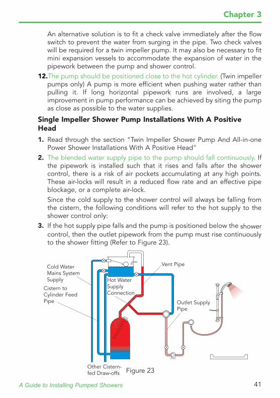
2. The blended water supply pipe to the pump should fall continuously. If the pipework is installed such that it rises and falls after the shower control, there is a risk of air pockets accumulating at any high points. These air-locks will result in a reduced flow rate and an effective pipe blockage, or a complete air-lock.
Since the cold supply to the shower control will always be falling from the cistern, the following conditions will refer to the hot supply to the shower control only:
3. If the hot supply pipe falls and the pump is positioned below the shower control, then the outlet pipework from the pump must rise continuously to the shower fitting (Refer to Figure 23).
Figure 23
A Guide to Installing Pumped Showers42
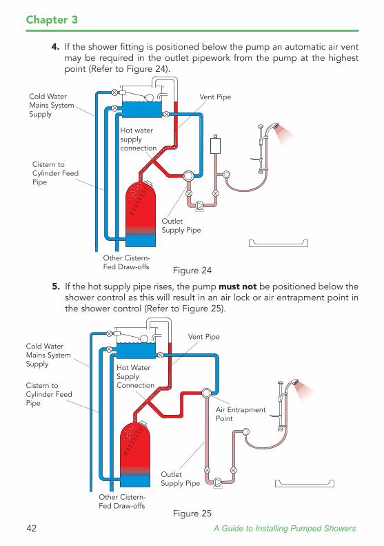
4. If the shower fitting is positioned below the pump an automatic air vent may be required in the outlet pipework from the pump at the highest point (Refer to Figure 24).
Chapter 3
Cold Water Mains System Supply
Cistern to Cylinder Feed Pipe
Other Cistern-Fed Draw-offs
Vent Pipe
Hot water supply connection
Outlet Supply Pipe
5. If the hot supply pipe rises, the pump must not be positioned below the shower control as this will result in an air lock or air entrapment point in the shower control (Refer to Figure 25).
Cold Water Mains System Supply
Cistern to Cylinder Feed Pipe
Other Cistern-Fed Draw-offs
Vent Pipe
Hot Water Supply Connection
Outlet Supply Pipe
Air Entrapment Point
Figure 25
Figure 24
A Guide to Installing Pumped Showers 43
Chapter 3
6. Pipe runs should be as short as possible to avoid excessive dead legs.Long lengths of pipe from the cylinder to the shower control should be avoided as the water in the pipe will cool during periods of no-flow. This volume of water will have to be drawn off before water at the correct temperature is available for showering. This is not only wasteful but the long lengths of pipe cause a pressure loss which allows the release of air from water.
7. The spray head must be positioned a minimum distance below the cistern to provide an adequate flow rate to ensure automatic operation of the flow switches (if fitted). When the shower is initially opened, a small amount of flow will take place due to gravity. Once this reaches the minimum level required to activate the flow switch, the electric circuit in the pump will operate and cause the pump to start. The minimum distance between the base of the cistern and the shower fitting, required to start the pump will be specified by the manufacturer. Refer to Chapter 3 "Methods of starting shower pumps" for further advice.
8. The pump should be positioned in the pipe run to ensure maximum efficiency. A pump is more efficient at pushing water rather than pulling it. If long horizontal pipework runs are involved, a large improvement in pump performance can be achieved by siting the pump as close as possible to the shower control. If this is physically impossible, the low pressure in the horizontal pipework, caused by the suction of the pump and the pressure loss due to the pipe itself, may induce air in solution to be dissipated from the water. Float-type automatic air vents cannot be installed prior to the pump to remove this air, as they could allow air to enter the pipework.
Pumped Shower Installations with a Negative Head
1. The shower control, pump, flow switches and all pipework except the outlet must be installed so that they flood naturally. It is important that the pipework and fittings in the plumbing system are below the level of water in the cold cistern at all times, (excluding the final section of pipework to the shower fitting which will be above this level). It is possible for the shower control to be above the level of the water in the cold cistern, although check valves would need to be fitted in both hot and cold inlet supplies to the shower control. Any section of pipework above the cold water level will develop air pockets, which could prevent flow from taking place due to air locking. If the pump or all-in one does not remain flooded at all times and is started whilst dry, then product damage may result.
A Guide to Installing Pumped Showers44
Chapter 3
The pump inside an all-in-one is typically activated by a micro-switch which removes the need to provide an external switching method. However, the minimum head required by the all-in-one should still be observed as this ensures the pump remains primed.
2. A method of starting the pump will be required. To enable the pump to start a suitable switching method will be required. Refer to Chapter 3 "Methods of starting shower pumps" for further advice.
All-in-one Pumped Electric Showers
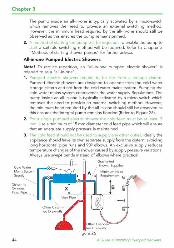
Note! To reduce repetition, an "all-in-one pumped electric shower" is referred to as a "all-in-one".1. Pumped electric showers require to be fed from a storage cistern.
Pumped electric showers are designed to operate from the cold water storage cistern and not from the cold water mains system. Pumping the cold water mains system contravenes the water supply Regulations. The pump inside an all-in-one is typically activated by a micro-switch which removes the need to provide an external switching method. However, the minimum head required by the all-in-one should still be observed as this ensures the integral pump remains flooded (Refer to Figure 26).
2. For a single pumped electric shower the cold feed must be at least 5 mm. Use a minimum of 15 mm diameter cold feed pipe which will ensure that an adequate supply pressure is maintained.
3. The cold feed should not be used to supply any other outlet. Ideally the appliance should have its own separate supply from the cistern, avoiding long horizontal pipe runs and 900 elbows. An exclusive supply reduces temperature changes of the shower caused by supply pressure variations. Always use swept bends instead of elbows where practical.
X B
ACold Water Mains System Supply
Cistern to Cylinder Feed Pipe
Other Cistern-fed Draw-offs
Other Cylinder-fed Draw-offs
Vent Pipe
Minimum Head Requirement
Gravity-fed Shower Supplies
Figure 26
A Guide to Installing Pumped Showers 45
Chapter 3
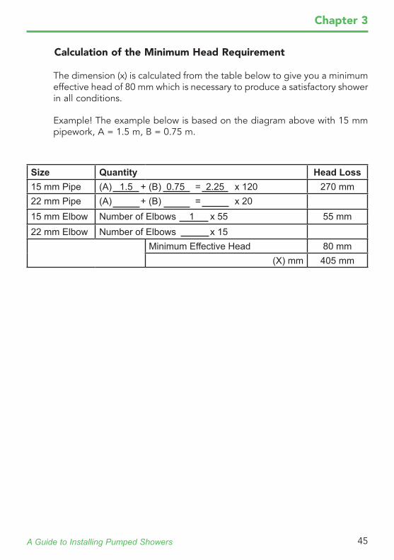
The dimension (x) is calculated from the table below to give you a minimum effective head of 80 mm which is necessary to produce a satisfactory shower in all conditions.
Example! The example below is based on the diagram above with 15 mm pipework, A = 1.5 m, B = 0.75 m.
Calculation of the Minimum Head Requirement
Size Quantity Head Loss15 mm Pipe (A) 1.5 + (B) 0.75 = 2.25 x 120 270 mm22 mm Pipe (A) + (B) = x 2015 mm Elbow Number of Elbows 1 x 55 55 mm22 mm Elbow Number of Elbows x 15
Minimum Effective Head 80 mm(X) mm 405 mm
A Guide to Installing Pumped Showers46
Chapter 3
The Pressure Switch This type of switch responds to a change of pressure within a section of
pipe to either make or break the electrical circuit to the pump. The pressures at which these switches operate are usually adjustable over the manufacturers stated pressure range and are set with two controls.
Flow
Flow
Push-fit Connectors
Figure 27
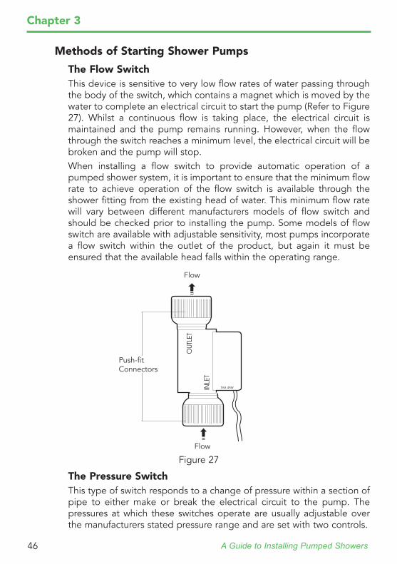
Methods of Starting Shower Pumps
The Flow Switch This device is sensitive to very low flow rates of water passing through
the body of the switch, which contains a magnet which is moved by the water to complete an electrical circuit to start the pump (Refer to Figure 27). Whilst a continuous flow is taking place, the electrical circuit is maintained and the pump remains running. However, when the flow through the switch reaches a minimum level, the electrical circuit will be broken and the pump will stop.
When installing a flow switch to provide automatic operation of a pumped shower system, it is important to ensure that the minimum flow rate to achieve operation of the flow switch is available through the shower fitting from the existing head of water. This minimum flow rate will vary between different manufacturers models of flow switch and should be checked prior to installing the pump. Some models of flow switch are available with adjustable sensitivity, most pumps incorporate a flow switch within the outlet of the product, but again it must be ensured that the available head falls within the operating range.
A Guide to Installing Pumped Showers 47
Chapter 3
The Pull-cord Switch If automatic operation of the pump is not required, it is possible to install
a suitably rated pull-cord switch, located in the vicinity of the shower. This would simply provide a manual on/off function of the pump regardless of whether the shower control was open or closed. If this method of pump control is adopted, it is obvious that the pump needs to be manually turned on, but when showering is finished and the flow control is closed the switch must also be turned off. Running the pump into a closed outlet would result in damage to the product.
The Momentary Action Pull-cord Switch and Flow Switch Combination
In installations where insufficient positive head prevents the automatic operation of a flow switch, then a momentary action pull-cord switch, electrically wired in parallel to the flow switch, can be included to initially start the pump. The momentary action switch will only complete the electrical circuit to the pump whilst the cord is pulled. When the shower's flow control is opened and then the cord is pulled, the pump will start generating flow which energises the flow switch.
The electrical circuit through the flow switch will be completed allowing the pull-cord switch to be released. The pump will then remain running. When showering is finished and the shower's flow control is closed, the flow switch will break the electrical circuit and the pump will switch off. This method of starting the pump provides semi-automatic operation, but with the advantage that it is impossible to inadvertently leave the pump running when the shower control is closed.
The first control sets the initial operating pressure at which the switch is required to turn on (or off). The second control is used to set the pressure difference from the initial operating pressure, at which the switch performs its subsequent off (or on) operation.
A Guide to Installing Pumped Showers48
Chapter 4
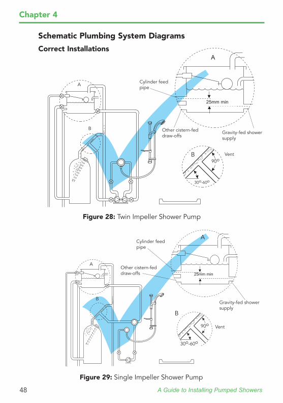
Schematic Plumbing System Diagrams
Correct Installations
A
Other cistern-fed draw-offs
Vent
Gravity-fed shower supply
Figure 28: Twin Impeller Shower Pump
A
B
Cylinder feed pipe
25mm min
B
30o-60o
90o
AOther cistern-fed draw-offs
Vent
Gravity-fed shower supply
Figure 29: Single Impeller Shower Pump
A
B
Cylinder feed pipe
25mm min
B
30o-60o
90o
A Guide to Installing Pumped Showers 49
Chapter 4
A
Other cistern-fed draw-offs
Vent
Gravity-fed shower supply
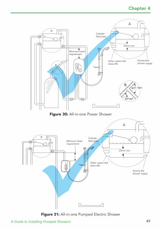
Figure 30: All-in-one Power Shower
A
B
Cylinder feed pipe
25mm min
B
30o-60o
90o
Minimum head requirement
Figure 31: All-in-one Pumped Electric Shower
A
Other cistern-fed draw-offs
Gravity-fed shower supply
A
Cylinder feed pipe
25mm min
Minimum head requirement
A Guide to Installing Pumped Showers50
Chapter 4
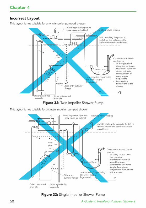
Avoid high-level pipe runs (may cause air locking)
Strained hose
Isolating valves missing
Vent pipe
Avoid installing the pump in the loft as this will reduce the performance and could freeze
Figure 32: Twin Impeller Shower Pump
Incorrect LayoutThis layout is not suitable for a twin impeller pumped shower
Hose retaining ring missing (see water supply Regulations)
Side entry cylinder flange
Connections marked * can lead to:- air being sucked
down the vent pipe- insufficient volume of
stored hot water- contravention of
water supply Regulations
- temperature fluctuations at the shower
Other cistern-fed draw-offs
Other cylinder-fed draw-offs
*
*
* *
Avoid high-level pipe runs (may cause air locking)
Strained hose
Other cistern-fed draw-offs
Other cylinder-fed draw-offs
Isolating valves missing
Vent pipe
Avoid installing the pump in the loft as this will reduce the performance and could freeze
Figure 33: Single Impeller Shower Pump
This layout is not suitable for a single impeller pumped shower
Hose retaining ring missing (see water supply Regulations)
Side entry cylinder flange
Connections marked * can lead to:- air being sucked down
the vent pipe- insufficient volume of
stored hot water- contravention of water
supply Regulations- temperature fluctuations
at the shower
* *
*
*
A Guide to Installing Pumped Showers 51
Chapter 4
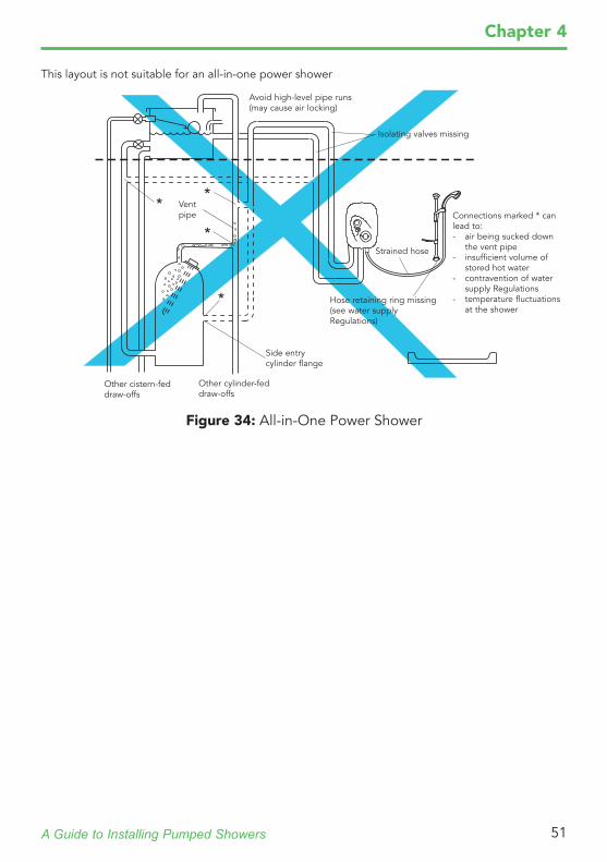
This layout is not suitable for an all-in-one power shower
Avoid high-level pipe runs (may cause air locking)
Strained hose
Other cistern-fed draw-offs
Other cylinder-fed draw-offs
Isolating valves missing
Vent pipe
Figure 34: All-in-One Power Shower
Hose retaining ring missing (see water supply Regulations)
Side entry cylinder flange
Connections marked * can lead to:- air being sucked down
the vent pipe- insufficient volume of
stored hot water- contravention of water
supply Regulations- temperature fluctuations
at the shower*
* *
*
A Guide to Installing Pumped Showers52
Key Installation TipsThe following two sections have been compiled by the expert staff in the Mira Customer Services Department, who are responsible for providing pre and post-installation telephone advice to installers. Drawing on their collective experiences the staff have prepared a list of key tips to enable the installer to achieve the best possible performance out of a Mira domestic pumped shower system.1. Before you purchase a pump or power shower, check that the plumbing
system is capable of supporting the increased demand required by high performance showering. This refers to not only the inlet supplies, but waste water outlet supplies.
2. Pumps must not be connected to the cold water mains system.3. A pump is more effective pushing water than pulling it.4. Installing a pump at high level, e.g. in the loft, will result in inferior
performance and possible freezing as most pumps are air cooled and cannot be insulated.
5. Water pumps can develop leaks and should not be fitted where seepage may go undetected.
6. Install the pump in a position where it can be easily accessed for routine maintenance.
7. All-in-one power showers installed on reverberant panels, e.g. plaster board partition walls, may accentuate pump motor noise.
8. Pump outlet pipework, which forms an air entrapment point, should be fitted with a float type automatic air vent at the highest point of the pipework run.
9. The hot take-off for the pump or power shower must be teed from the vent pipe as shown in Chapter 2 "Hot water supply connection".
10.An independent cold water supply should be taken direct from the cistern to the pump or power shower.
11.Free flowing isolating valves should fitted in the water supplies to a pump or power shower, to allow the routine maintenance or servicing of the appliance. In the case of a separate pump, isolating valves should be fitted to both the inlet and outlet supplies.
12.During installation and before commissioning, care must be taken to protect the case of the pump or power shower from damage:
Some solder fluxes are very corrosive and can seriously damage some plastic components.
The use of jointing paste is not recommended or required. Prior to commissioning, make sure the plumbing system is thoroughly
flushed through, as large pieces of debris e.g. solder, can seriously damage the internal components of the pump or power shower.
Cus
tom
er S
ervi
ces
- 08
44 5
71 5
000
Chapter 5
A Guide to Installing Pumped Showers 53
Question and Answer Troubleshooting TipsQ. The pump (or power shower) seems to cause excessive vibration through
the supply pipework, is this normal?A. If the pump is fitted with flexible hoses then these should not be bent more
than 30º from vertical. Installation of additional flexible hoses will provide further acoustic de-coupling.
A. Ensure that there is a gap around pipework running under floor boards or through joists. Ideally the pipe should be sleeved with foam insulation to reduce transmitted noise.
A. Standing the pump on high density material, e.g. a concrete paving slab, will dramatically reduce transmitted noise through floor boards and joists.
Q. The power shower is fitted onto a panel wall and it's noisy, why?A. The installation of a fabricated rubber mounting between the wall and the
product will reduce the amount of transmitted motor noise.A. The use of plastic plumbing pipe will reduce transmitted noise compared
to rigid copper pipe.Q. Why does my pump (or power shower) not start?A. Is electricity being supplied to the pump or power shower? Check the
electrical supply fuses. If the electrical supply is reaching the product, then check: Is there sufficient head of water? Is the shower head blocked? Are the inlet
filters on the pump or power shower blocked? Are the float sensors in the flow switch free to move?
Q. Why does the pump (or power shower) run continuously?A. If the pump incorporates flow switches and runs continuously, then the float
sensors may be stuck. Depending on the design of the flow switch, the sensors may be removed and cleaned. Pumps that do not incorporate flow switches are likely to have a specific internal fault. Refer to the fault diagnosis section in the product's Installation and User Guide.
Q. The pump pulsates on/off alter the shower's flow control has been shut off, why does it do this?
A. If an air pocket exists downstream of the pump, water will move through the flow switch in response to the shut-off of the shower's flow control. If this flow is sufficient, the pump will start. Once the air pocket is sufficiently compressed the flow switch will turn the pump off again. Check that there are no air-locks in the plumbing system and re-route any suspect pipework, alternatively install float type automatic air vents. If neither of these solutions are possible then install check valve/s on the outlet side of the pump to prevent the movement of water. Note! The fitting of check valves may increase the head of water required to start the pump.
Cus
tom
er S
ervi
ces
- 08
44 5
71 5
000
Chapter 5
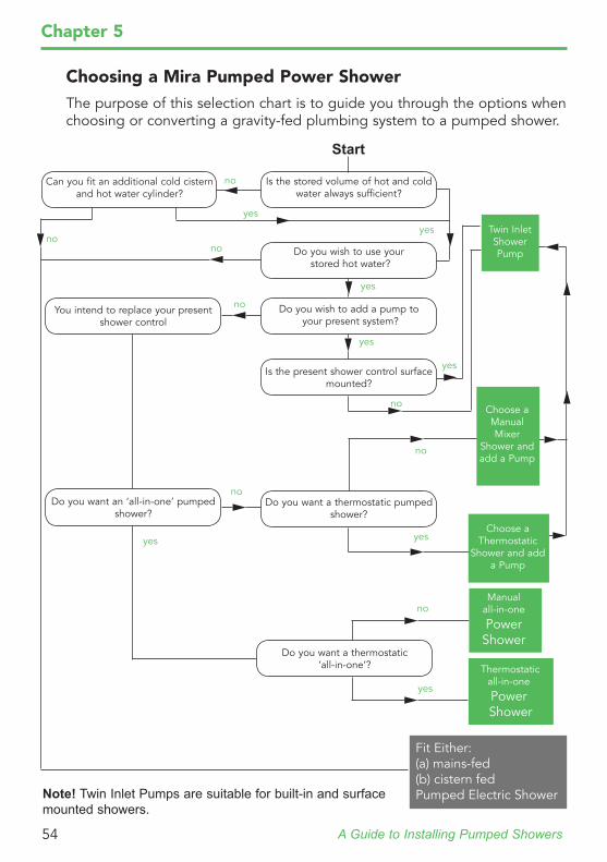
A Guide to Installing Pumped Showers54
Chapter 5
Choosing a Mira Pumped Power ShowerThe purpose of this selection chart is to guide you through the options when choosing or converting a gravity-fed plumbing system to a pumped shower.
Can you fit an additional cold cistern and hot water cylinder?
Is the stored volume of hot and cold water always sufficient?
Do you wish to use your stored hot water?
You intend to replace your present shower control
Do you wish to add a pump to your present system?
Is the present shower control surface mounted?
Do you want an ‘all-in-one’ pumped shower?
Do you want a thermostatic pumped shower?
Do you want a thermostatic ‘all-in-one’?
Start
no
nono
no
no
no
no
no
yes
yes
yes
yes
yes
yes
yes
yes
Note! Twin Inlet Pumps are suitable for built-in and surface mounted showers.
Choose a Manual Mixer
Shower and add a Pump
Choose a Thermostatic
Shower and add a Pump
Manualall-in-one
PowerShower
Thermostaticall-in-one
Power Shower
Fit Either:(a) mains-fed(b) cistern fedPumped Electric Shower
Twin Inlet Shower Pump

A Guide to Installing Pumped Showers 55
Customer SupportA service you can depend onAt Mira we know our excellent reputation depends on the service we provide. That’s why we’re passionate about looking after our customers. We have a dedicated Customer Services Team to provide lifetime support for your Mira product. From general advice and problem diagnosis through to supplying spare parts or arranging a service engineer visit, they’re waiting to help.We know our customers prefer talking to friendly human beings rather having to work through automated systems, or left to listen to tedious hold music. That’s why 85% of all calls are answered within 15 seconds by a Customer Service representative. Each representative has undergone extensive initial training and typically completes a further minimum 150 hours each year. They know every Mira product inside out so can help no matter what question you have.
After Sales AssistanceLooking after your Mira showerIf you ever need hands-on help, we have a team of field based engineers helping Mira installers and owners get the most from their showers. Even if your warranty has expired, we’re still here to help. We only charge by the visit and not by the hour, so you can be sure you’re getting exceptional value for money.• We aim to complete 75% of service visits within 3 working days of
receiving a customer’s call• We aim to achieve a first time fix rate of 98%• Spare parts are despatched within 2 working days of your call (subject to
stock availability).At the end of the day, the service you receive has to be as good as the product you enjoy. With Mira, you know you’ll enjoy the best of both worlds.
Cus
tom
er S
ervi
ces
- 08
44 5
71 5
000
Chapter 6
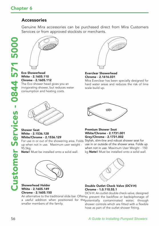
A Guide to Installing Pumped Showers56
Cus
tom
er S
ervi
ces
- 08
44 5
71 5
000
Chapter 6
Eco ShowerheadWhite - 2.1605.110Chrome - 2.1605.112The Eco shower head gives you an invigorating shower, but reduces water consumption and heating costs.
Everclear ShowerheadChrome - 2.1616.031Mira Everclear has been specially designed for hard water areas and reduces the risk of lime scale build up.
Showerhead HolderWhite - 2.1605.149Chrome - 2.1605.150An alternative to the traditional slide bar. Often a useful addition when positioned for the smaller members of the family.
Shower SeatWhite - 2.1536.128White/Chrome - 2.1536.129For use in or out of the showering area. Folds up when not in use. Maximum user weight - 95.5kg.Note! Must be installed onto a solid wall.
Double Outlet Check Valve (DCV-H)Chrome - 1.0.110.55.1DCV-H: An outlet double check valve, designed to prevent the backflow or backsiphonage of potentially contaminated water, through shower controls which are fitted with a flexible hose as part of the outlet shower fitting.
AccessoriesGenuine Mira accessories can be purchased direct from Mira Customers Services or from approved stockists or merchants.
Premium Shower SeatWhite/Chrome - 2.1731.001Grey/Chrome - 2.1731.002Stylish, slim-line and robust shower seat for use in or outside of the shower area. Folds up when not in use. Maximum User Weight - 150 kg Note! Must be installed onto a solid wall.

A Guide to Installing Pumped Showers 57
KOHLER® Family of BusinessesKohler Co. is one of the world leaders in bathroom design, setting the standard for innovation, craftsmanship and new technology across the globe since 1873.Kohler in the UK encompasses its market leading domestic brands - KOHLER, MIRA® and RADA®, offering an inspirational collection of bathroom sanitaryware, bathroom furniture, taps, showers and shower enclosures.• Mira, established in 1921, we have been leading the way in UK
showering for decades. In 1937 we introduced the world’s first ever thermostatic shower, designed specifically for hospitals and schools. Mira mixer valves quickly became the standard equipment for the shower market and in 1959 we unveiled the first thermostatic shower for domestic use. Ever since then our showers have remained firm favourites with households across the UK.
• Rada controls, the commercial sector of Mira, manufacture mixer valves, washroom products, electronic products, shower fittings and accessories suitable for Health Care, Commercial and Industrial applications.
• Designer bathroom suites from Kohler UK span contemporary and traditional styles with a wide range of sinks and washbasins, taps, showers and shower enclosures, bathroom accessories and bathroom furniture, fitted and freestanding. The collection includes decorated and handcrafted bathroom sinks and washbasins, which can be pedestal-mounted, furniture-mounted or wall-hung. Also, monobloc taps and wall-mounted taps as well as back-to-wall WCs and wall-hung toilets and bidets. In addition, we offer everything for the spa bathroom: whirlpool spa baths and bath tubs with hydrotherapy and chromatherapy.
For more information about our range of products, or to register your guarantee, download additional user guides, diagnose faults, purchase our full range of accessories and popular spares, refer to our FAQ’s and request a service visit please call us or visit the Web sites below.
www.mirashowers.co.ukwww.radacontrols.comwww.kohler.co.uk

A Guide to Installing Pumped Showers58
Chapter 6

GETTING IN TOUCHIf you live in the UK or Northern Ireland and have a question about our products or would like to talk to Mira Customer Services, please call us on 0844 571 5000. If you live in the Republic of Ireland, please call us on 01 531 9337. Alternatively you can visit our website: www.mirashowers.co.uk/contactus or www.mirashowers.ie/contactus
If you’d like to find out where your nearest stockist is, or you’d like to order a brochure, please call us on the numbers above or visit our website.
KOHLER® FAMILY OF BUSINESSESWe’re owned by Kohler Co., one of the world leaders in bathroom design. Kohler has been setting the standard for innovation, craftsmanship and new technology across the globe since 1873.
Kohler in the UK brings together a number of market-leading bathroom and shower brands, including Kohler, Mira Showers and Rada to bring you an inspiring collection of bathroom sanitaryware, bathroom furniture, taps, showers and shower enclosures.
If you’d like to know more about the range of Kohler and Rada products, please visit www.kohler.co.uk and www.radacontrols.co.uk
IMPORTANT INFORMATIONWe recommend that you should read the Installation and User Guide (IUG) supplied with each product before installing it. If you are in any doubt, give our customer services team a call on 0844 571 5000 (UK & NI) or 01 531 9337 (ROI).
We are constantly looking to improve our products wherever we can, so we reserve the right to make
product changes without prior notice.

© 2013 by Mira Kohler Mira Ltd. Cromwell Road, Cheltenham, Gloucestershire, GL52 5EP, United Kingdom Brochure Enquiries: 0844 571 0005 (UK & NI): 01 531 9337 (ROI) Customer Services: 0844 571 5000 (UK & NI): 01 531 9337 (ROI)
1108903-W2-B
www.mirashowers.co.uk


