114
miroVIDEO DV200 USER´S GUIDE

miroVIDEO DV200USER´S GUIDE

miroVIDEO DV200User´s GuideVersion 1.0/GB March 1999160594© Pinnacle Systems 1999All rights reserved.No part of this manual may be reproduced or transferred to other media without explicit written permissionfrom Pinnacle Systems, Braunschweig, Germany.
Adobe™ and Acrobat™ are trademarks of Adobe Systems Inc.FireWire™ is a trademark of Apple Computers, Inc.IBM AT® is a registered trademark of International Business Machines Corp.miroVIDEO™ and miroINSTANT Video™ are trademarks of Pinnacle Systems Inc.Pentium™ is a trademark of Intel Corp.Sony® is a registered trademark of Sony Corp.Windows® and MS-DOS® are registered trademarks of Microsoft Corp.All other brand and product names are trademarks or registered trademarks of their respective holders.
This manual is printed on chlorine-free paper using environmentally safe ink.Pinnacle Systems has written this manual to the best of its knowledge, but does not guarantee that theprograms/systems will fulfill the desires of the user.No warranty is made as to the specifications of features.Pinnacle Systems retains the right to make alterations to the content of the manual without the obligation toinform third parties.All tenders, sales, supply and manufacturing contracts from Pinnacle Systems, including consulting,installation and other contractual performance are subject exclusively to the General Sales and DeliveryTerms of Pinnacle Systems.

User´s Guide i
Contents
OVERVIEW 1
BEFORE YOU START 2
SYSTEM REQUIREMENTS 2DEFRAGMENTING THE HARD DISK 4PACKAGE CONTENTS 4
QUICK START 5
QUICK INSTALLATION 5SCANNING DV (QUICK START) 6VIEWING CLIPS AND ADDING TRIMS (QUICK START) 6CAPTURING DV (QUICK START) 7EDITING AVI FILES USING ADOBE PREMIERE (QUICK START) 7PRINTING TO DV (QUICK START) 7CAPTURING SINGLE FRAMES (QUICK START) 8
INSTALLING ADOBE PREMIERE 9
INSTALLATION 10
INSTALLING THE SOFTWARE 12
INSTALLING DRIVERS FOR WINDOWS 95 13INSTALLING THE DRIVERS FOR WINDOWS 98 15INSTALLING THE SOFTWARE FOR WINDOWS 95 / WINDOWS 98 16INSTALLING SOFTWARE FOR WINDOWS NT 4.0 19INSTALLING THE DV200 SOFTWARE LATER 23UNINSTALLING THE DV200 SOFTWARE AND DRIVERS 23
CONNECTING THE DEVICES 24
ATTACHING A DV CAMCORDER OR A DV VCR 24CONNECTING THE TV SET/VIDEO MONITOR 25
WORKING WITH DV MATERIAL 27
MAKING MOVIES 27CAPTURING SINGLE FRAMES (SNAPSHOTS) 37
miroVIDEO DVTOOLS 40
CAPTURE GALLERY 40TAPE GALLERY 45DV DEVICE CONTROLLER 45miroINSTANT VIDEO PLAYBACK 51

ii miroVIDEO DV 200
miroVIDEO DV200 & ADOBE PREMIERE 4.2LE 53
ADOBE PREMIERE PROJECT PRESETS 53THUMBNAIL ACCELERATION 54miroINSTANT VIDEO 2.0 55WORKING WITH miroVIDEO DV200 AND A BOARD OF THE miroVIDEO DC30 SERIES
59
miroVIDEO DV200 & ADOBE PREMIERE 5.1 61
INSTALLATION 62PRESETS 62CAPTURE VIDEO WITH ADOBE PREMIERE 5.1 64DEVICE CONTROL WITH ADOBE PREMIERE 5.1 66miroINSTANT VIDEO 5.0 72
TIPS & TRICKS 81
HARDWARE 81SOFTWARE 82DV TAPE 82
TROUBLESHOOTING 83
TECHNICAL DATA 87
APPENDIX I
CONFIGURING THE DV200 IIDENTIFYING THE WINDOWS 95 VERSION VIUNINSTALLING miroVIDEO DV200 DRIVERS AND SOFTWARE VIICHANGING THE NUMBER OF COLORS AND SCREEN RESOLUTION VIICOMPATIBLE DV DEVICES VIITV STANDARDS VIIIGLOSSARY X
INDEX

User´s Guide iii
About the manual
This manual explains how to install and use the miroVIDEO DV200hardware and software. Instead of using the complete product designation(miroVIDEO DV200), the abbreviation DV200 is used to ensure a betterreadability.
The following conventions are used in this manual:
In the margins are subheadings to help you quickly find your way throughthis manual.
Important text passages are marked with the ”notepad” and this format.
Numbers mark step-by-step instructions:
1. Switch on the computer.
Bullets mark instructions for optional steps, if the order is not important.
• Connect the 1394 cable to the DV200 board.
All keyboard commands appear in this font:
install
Menus, commands, options or buttons are written in italics.
1. From the Start menu, select the Run ... command.
Subheadings

iv miroVIDEO DV 200
For your own safety
In the interest of your own safety and the proper functioning of your newproduct and computer system please note the following:
s Computer components are sensitive to static charge. Divert anyelectrostatic charge before touching the components with your hands orany tools. To do so, touch the casing of your computer.
s Before opening the computer make sure that the power plug isdisconnected from the wall outlet.
For changes or supplements that could not be included in the printed or inthe online documentation, refer to the ReadMe file/s on the CD-ROMsupplied with your system!

User´s Guide 1
Overview
With the introduction of the digital video camcorders, it is now possible toshoot, store and produce video productions entirely in digital format. In avideo production sense, first-generation quality is maintained through-out allproductions. The traditional loss in analog video production does not applyand every digital copy is the same quality as the original.
The miroVIDEO DV200 is a complete hardware and software solutionwhich allows you to connect your DV digital camcorder or DV VCR(equipped with a IEEE-1394 interface) to your computer. The DV200transfers data stored on the DV camcorder tape into the computer. Once inthe computer miroVIDEO DVTools software allows you to index, arrange,store and edit your DV video footage. The miroVIDEO DVTools alsoallows you to save the edited video clips back to the DV tape. The product isintended for those users who have PCI bus-based systems runningWindows 95, Windows 98 or Windows NT.
The miroVIDEO DV200 is a state-of-the-art PCI bus mastering expansionboard . The board connects to the DV camcorder through themiroVIDEO DV200 1394 DV cable. The board includes the following connectors:s two external 6-pin 1394 connectorss one internal 6-pin 1394 connector.
The miroVIDEO DV200 software includes:s the miroVIDEO DV200 drivers,s miroVIDEO DVTools, a software for capturing DV clips and record the
clips back to the DV tape*,s Adobe Premiere LE (Light Edition),
s Presets for Adobe Premiere,s miroINSTANT Video 2.0, a plug-in for Adobe Premiere which
accelerates the making of movies considerably,s intro files for miroINSTANT Video which help you switch on your VCR
very precisely when you start recording,s one ten second and one 30 second silent audio clip for use in blank spaces
of premiere ten seconds or longer,s miroINSTANT Video 5.0, a plug-in for Adobe Premieres miroVIDEO DV Capture, a capture plug-in for Adobe Premiere 5.1s miroVIDEO DV Device control, a device control plug-in for Premiere 5.1
for DV devices.s DVExpert, a system performance and 1394 test utility.s miroVIDEO DV200 Configuration, a configuration tool.
* Not all devices support the recording of video clips via the DV connector.
Hardware
Software

2 miroVIDEO DV 200
Before you start
Before installing the tools, please completely uninstall of the former softwareversions, including possible update versions.
During the installation, make sure no 1394 DV devices are connected to theboard, as they could interfere with the initialization of the driver.
This chapter tells you which requirements your system has to meet foroperating the DV200 board, which devices you can connect to the board andwhat is included in the package contents.
SYSTEM REQUIREMENTS Please make sure your system meets the following requirements beforeinstalling the miroVIDEO DV200:
ComputerPCI-based Pentium II 233 MHz computer with a free PCI-2.1 compliant slot.New computers only have PCI-2.1 compliant slots. For more information,please read the documentation that was supplied with your computer system.
MemoryAt least 64 MB memory. Recommended: 128 MB.
Hard diskHard disk with a sufficient data transfer rate and storage capacity. For furtherdetails, refer to the following:
s Data transfer rate:The DV format is fixed at a 5:1 compression ratio. The data transfer rateneeded to transfer real-time from the DV camcorder is approximately3.6 MB/s. The transfer rate of your hard disk has to be at least 5 MB/s.
Hard disk capacity:The DV200 drivers and miroVIDEO DVTools need approximately 20 MB ofhard drive space. Adobe Premiere 4.2LE needs about 16 MB hard drivespace. Adobe Premiere 5.1LE needs about 30 MB of hard disk space..Raw DV formatted video occupies 3.6 MB for each second of content. Forexample, four minutes of DV video would occupy approx. 900 MB (withsplitted audio) of disk space. While DVTools takes care to minimize thespace used on your hard disk, it is recommended that you use a hard diskwith sufficient capacity.
To accelerate capturing and playing back a large amount of data, werecommend that you defragment your hard disk/s before capturing/playingback video. Under Windows 95/Windows 98 you will find a de-fragmentation utility under Start, Programs, Accessories, System Tools, DiskDe-fragmenter. Under Windows NT no defragmentation utility is available.If you are using Windows NT, please use a de-fragmentation utility you canobtain or from your computer store.
Hardware

User´s Guide 3
Graphics board and monitorA graphics system with at least 16 bits color depth (65,000 colors) and a 800x 600 resolution is required. We recommend a graphics system that supportsDirect Media 6.x.
Windows 95 (recommended: OSR 2.1), Windows 98, Windows NT 4.0.
NTSC devices (Capture and print to tape):Devices that connect to the board include any DV format video equipmentthat has an IEEE-1394/DV connector, such as devices from Sony, Panasonic,Canon, JVC or Sharp.
PAL devices:
s Capture (transfer of DV data from the video device to the computer):Devices that connect to the board include any DV format videocamcorder or recorder that has an IEEE-1394/DV connector.
s Print to tape (Transfer of DV data from the computer back to the tape):Note that not all PAL DV devices available on the market support aplayback back to the camcorder. Please refer the documentation thatcomes with your camcorder/VCR. If you want to playback to analogVCR’s, you can also playback your video back to (analog) tape using themiroVIDEO DC30 or miroVIDEO DC30 plus boards.
For more information on video standards (PAL, NTSC) refer to theAppendix on page VII. You will find a list of compatible devices in theAppendix on page VII and in the readme file.
To be able to check the quality of your video footage during editing, a TVset or a video monitor is required. (Some camcorders have an integrateddisplay. If you own such a device, you do not necessarily have to connect amonitor.) In case you do not want to connect a TV set or video monitor toyour DV device, you can always use the preview window provided in themiroVIDEO DVTools, though the quality and size is limited.To connect a television/video monitor to your camcorder/VCR, you need aS-Video or a composite cable or a cinch cable for the audio inputs/outputs.
Software
DV Devices
TV/video monitor
Cable

4 miroVIDEO DV 200
DEFRAGMENTING THE HARD DISK
Before installing and configuring the DV200 you should de-fragment yourhard disk/s. You find the Windows 95/Windows 98 defragmentation utilityunder Start, Programs, Accessories, System Tools, Disk De-fragmenter.Under Windows NT no de-fragmentation utility is available. If you are usingWindows NT, please use a de-fragmentation utility you can obtain from yourcomputer store.
PACKAGE CONTENTS
Make sure your miroVIDEO DV200 kit is complete before you begin theinstallation. The system includes*:
miroVIDEO DV200 board** IEEE-1394 DV cable
Adobe Premiere and documentation*** CD-ROM with driver software,miroVIDEO DVTools, Presets and driversfor Adobe Premiere
User´s Guide
If any parts are missing, please contact your retailer.
Computer components are sensitive to electrostatic charge. Do not take themiroVIDEO DV200 board out of its antistatic package until you install it.
* The package contents may vary from the contents listed in this manual.** For an exact model name and serial number of your board, refer to the label on the board.*** As soon as Adobe Premiere 5.1LE will be available, this version of Adobe will be included in the delivery scope
of miroVIDEO DV200.

User´s Guide 5
Quick start
The following chapter shall help the experienced user to start using themiroVIDEO DV200 board immediately.For more detailed installation instructions, please refer to the subsequentchapters in the manual.
QUICK INSTALLATION
Install Adobe Premiere.þ Place the Adobe Premiere-CD-ROM in your CD-ROM drive.þ If the installation program is not started automatically, select Run…
from the Start menu.þ Depending on your drive,
for Adobe Premiere 4.2LE enter, for example:e:\english\win95&nt\disk1\setup,
for Adobe Premiere 5.1LE enter, for example:e:\premiere\setup,
then click OK.þ Follow the installation instructions on the screen.
Install the miroVIDEO DV200 board.þ Turn your computer and all peripherals off.þ Remove the necessary cables.þ Open the computer's housing.þ Remove the slot cover.þ Insert the board.
Reassemble the computer.þ Reassemble the computer.þ Reconnect all cables.
Install the miroVIDEO DV200 software.þ Place the CD-ROM in the CD-ROM drive.þ Follow the installation program instructions on the screen.
Connect the DV device to the DV200 board.þ Connect the DV device to the DV200 board using the IEEE-1394
cable.
Connect a video monitor/television to the DV device.þ Connect a video monitor or a TV set to the appropriate video output
of your DV device using the appropriate cable.
Establish the audio link.þ Connect an audio cable to the audio output of your DV device.þ Connect the other end of the audio cable to the audio input of your
video monitor/TV set.

6 miroVIDEO DV 200
SCANNING DV (QUICK START)
Test your system.Use the DVExpert from the miroVIDEO DV200 Program Group to testthe performance of your hard disk and your 1394 system.
Check preferences.Start DVTools from the miroVIDEO DV200 program group. From theTools menu, select Preferences and check the settings.
Turn on DV device.Turn on your DV device. Make sure that it is running in VTR mode.
Scan DV tape.From the Tools menu, select Scan DV tape. Scan additional tapes, ifdesired.
VIEWING CLIPS AND ADDING TRIMS (QUICK START)
Open a Tape Gallery.Double-click a tape gallery name in the DV Explorer.
Preview the clips.Double-click on a clip. In the Clip Info window click on the Eye button.
Choose the clips you want to capture.Drag and drop the clips from the Tape Gallery into the Capture Gallery.
Add trims.Define in and out points using the DV Device Controller.
Save the Capture Gallery file.Save the Capture Gallery using the Save as menu item from the Filemenu.

User´s Guide 7
CAPTURING DV (QUICK START)
Open a Capture Gallery.Open the Capture Gallery you want to capture.
Check the file size.Check the file size in the status bar at the bottom of the Capture Gallery.
Capture AVI files.Click on the Capture button on the right-hand side of the CaptureGallery.
Enter the file name and the directory.If you do not want to use the default drive which was determined in thePreferences window, select a drive and directory where you want tocapture the file/s and enter a file name for the first clip.
EDITING AVI FILES USING ADOBE PREMIERE (QUICK START)
Start Adobe Premiere.Click on the corresponding button on the right-hand side in the CaptureGallery.
Select a Preset.Select a suitable Preset from the Adobe Project Presets.
Import AVI file(s).From the File menu, select Import and File.
Edit AVI file(s).Add effects and edit your video.
Make a movie.From the Make menu, select Make Movie (Adobe Premiere 4.2LE).From the File menu, select Export (Adobe Premiere 5.1LE).
PRINTING TO DV (QUICK START)
Open the miroVIDEO DVTools.Click Program Files in the Start menu. Select the program groupmiroVIDEO DV200 and click on miroVIDEO DVTools.
Insert a new tape.Insert a new tape and rewind it to a position where you want to startrecording.

8 miroVIDEO DV 200
Select a file.Click on the Print-to-tape button on the right-hand side of the CaptureGallery. DVTools will prompt you to select the file you want to print totape. After selecting the file, the print-to-tape process will startimmediately.
CAPTURING SINGLE FRAMES (QUICK START)
Connect your DV equipment.If you haven't already, connect your DV camcorder or DV videorecorder to the DV200 board.
Turn on your DV equipment.Switch your DV device on. Select the desired mode (either VTR orCamera mode).
Open the DV Device Controller.To open the DV Device Controller, click on the (camera) icon in theDVTools window.
Create bitmap.Click on the (snapshot) button.
Name and save the BMP file.Enter a name and a location where you like to save your BMP file.
What's next?For more detailed instructions concerning any of the above functions, pleaserefer to the following chapters. You can also find information concerning theinstallation of a PCI expansion board in the documentation supplied withyour computer.

User´s Guide 9
Installing Adobe Premiere
The following chapter describes the procedure to install Adobe Premiere.
It is required that you install Adobe Premiere before installing themiroVIDEO DV200 board and software. The DV200 software installationprogram needs to know where the Adobe Premiere folders are located sothat it can copy the DV200 plug-ins and presets into the correspondingfolders.
Proceed as follows to install Adobe Premiere:
1. Place the Adobe Premiere CD-ROM in your CD-ROM drive.
2. If the installation program is not started automatically, select Run… fromthe Start menu.
3. Depending on your drive, enter, for example:
• for Adobe Premiere 4.2LE e:\english\win95&nt\disk1\setup.
• for Adobe Premiere 5.1LEe:\premiere\setup.
If your CD-ROM drive has a different drive designation, change the pathaccordingly.
—or—
4. Click on Browse..., switch to your CD-ROM drive and to the directorymentioned above and double-click the setup.exe file.
5. Click OK.
6. Follow the program installation instructions on the screen.
The complete Adobe Premiere documentation is available as PDF file on thecorresponding Adobe Premiere CD-ROM. You can view the documentationusing the Acrobat Reader. If the Acrobat Reader has not already beeninstalled on your computer, it will be installed together with your DV200software.
After you have installed Adobe Premiere on your computer, you can installthe miroVIDEO DV200 board.
Adobe Premieredocumentation

10 miroVIDEO DV 200
Installation
This chapter explains how to install the DV200 board.
Computer components are sensitive to electrostatic charge. Do not take themiroVIDEO DV200 board out of its antistatic package until you install it.
To install the board, you need a screwdriver.
To insert your DV200 board in your computer, proceed as follows:
1. Discharge electrostatic charge.
Discharge electrostatic charge by touching the metal case of yourcomputer.
2. Switch off the devices and pull the power cord.
Switch off the computer and all peripheral devices. Pull out the powercord and disconnect all necessary cables.
3. Open the computer.
Loosen the screws of the computer's cover and remove the cover. Keepthe screws in a safe place.
4. Select a slot.
Select a free PCI slot. PCI slots are the shorter ones available in yourcomputer and mostly made of white plastic. Make sure that the PCI slotyou use supports busmastering. If you are not sure about this, pleaseconsult your computer documentation.
Slots
Slot shields
Powersupplyunit
PCI slots
PCI slots
User´s Guide 11
5. Remove the slot shield.
Remove the screw and the slot shield for the PCI slot you have selected.Keep the screw because you will need it later to secure the board once itis installed.
6. Unpack the board.
Remove the DV200 from its sleeve.
You only need to connect the internal connector to your computer´s powersupply, if you plan to use devices such as video conferencing cameras thatrequire a 6-pin 1394 cable.
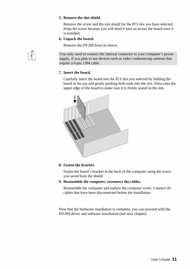
7. Insert the board.
Carefully insert the board into the PCI slot you selected by holding theboard at the top and gently pushing both ends into the slot. Press onto theupper edge of the board to make sure it is firmly seated in the slot.
8. Fasten the bracket.
Fasten the board´s bracket at the back of the computer using the screwyou saved from the shield.
9. Reassemble the computer, reconnect the cables.
Reassemble the computer and replace the computer cover. Connect allcables that have been disconnected before the installation.
Now that the hardware installation is complete, you can proceed with theDV200 driver and software installation (see next chapter).

12 miroVIDEO DV 200
Installing the software
Once you have installed the miroVIDEO DV200 into your computer, youcan install the miroVIDEO DV200 drivers and software. The installationsteps for the Windows 95 August Release, Windows 95 OSR2, Windows 98and Windows NT are slightly different.
Before installing the miroVIDEO DV200 drivers for Windows 95, werecommend you to identify the Windows version you use first.You can check which Windows 95 version you use by entering the DOScommand ver. The Windows 95 OSR 2 (OEM Service Release 2) versionhas the version number: Windows 95. [Version 4.00.1111] or [Version4.00.950b]; the August Windows 95 Release has the version number:Windows 95. [Version 4.00.950]. For detailed information on how to use theDOS ver command refer to the appendix in the section “Identifying theWindows 95 version” (page VI).
The complete installation consists of the following steps:
s Installing drivers for Windows 13
s Windows 95 (Release August 95) as of page 13, or
s Windows 95 (Release August 95) as of page 14.s Installing the software for Windows 95 / Windows 98 as of page 16.
If you use Windows 98, please proceed with the “Installing drivers forWindows 98” section on page 15. The complete installation consists of the following steps:
s Installing drivers for Windows 98 as of page 15.
s Installing the software for Windows 95 / Windows 98 as of page 16.
If you use Windows NT, please read the “Installing software forWindows NT 4.0” section as of page 19.
Among other things, installing the miroVIDEO DV200 software copies themiroVIDEO DV200 drivers to your hard disk. The miroVIDEO DV200program group is created, and—among other things—the expanded AdobePremiere project defaults (Presets) are copied to your hard disk.
Windows 95
Windows 98
Windows NT

User´s Guide 13
INSTALLING DRIVERS FOR WINDOWS 95
Windows 95 (Release August 95)1. Switch computer on.
Switch your computer on. Windows 95 is started automatically.If your computer is configured in such a way, that Windows 95 is notstarted automatically, please start Windows 95 now.
After Windows 95 starts, the New hardware found dialog box will appear.A PCI FireWire (IEEE 1394) will be detected.
2. Select Driver from disk provided by hardware manufacturer,click OK.
In the New hardware found dialog box, click the Driver from diskprovided by hardware manufacturer option. Click OK.
3. Insert CD-ROM.
Insert the installation CD-ROM into the CD-ROM drive.
4. Click Browse... . Click on the Browse... button.
5. Switch to the \DRIVER directory, click OK.
Switch to your CD-ROM drive and go into the \DRIVER directory.Select DV200.inf and click OK.
6. Click OK.
Click the OK button again.
After the drivers have been copied, the installation program startsautomatically. Proceed with the “ Installing the software for Windows 95 /Windows 98” section as of page 16.
Windows 95(Release
August 95)

14 miroVIDEO DV 200
Windows 95 (OSR 2)To install the drivers for the OSR2 Release, proceed as follows:
1. Switch on computer.
Switch on your computer. Windows 95 is started automatically. If yourcomputer is configured in such a way, that Windows 95 is not startedautomatically, please start Windows 95 now.
After Windows 95 starts, the New hardware component found dialog boxappears followed by the Update Device Driver Wizard dialog. A PCIFireWire (IEEE 1394) will be detected.
2. Click Next.
Click on the Next button.
3. Insert the CD-ROM.
Insert the installation CD-ROM into the CD-ROM drive.
4. Click Other Locations....
Click on the Other Locations... button.
5. Click Browse... . Click on the Browse... button.
6. Switch into the \DRIVER directory, click OK.
Switch to your CD-ROM drive and go into the \DRIVER directory. ClickOK.
7. Click Finish.
Click on the Finish button.
8. Click OK and Browse... again.
When your system requests you to insert the CD-ROM again, click on OKand once again on Browse... .
9. Switch into the \DRIVER directory, click OK.
Switch to your CD-ROM drive and go into the \DRIVER directory. ClickOK.
10.Click OK.
Click the OK button again.
Windows 95(OSR 2)

User´s Guide 15
After the drivers have been copied, the installation program startsautomatically. Proceed with the “ Installing the software for Windows 95 /Windows 98” section as of page 16.
INSTALLING THE DRIVERS FOR WINDOWS 98Microsoft provides Windows 98 with own drivers for 1394 bus boards.
1. Switch on computer.
Switch on your computer. Windows 98 is started automatically.
If your computer is configured in such a way, that Windows 98 is notstarted automatically, start Windows 98 now.
After Windows 98 starts, the new hardware is found, and the Add NewHardware Wizzard dialog appears.
2. Click Next. Click on the Next button.
3. Select Display a list of all drivers in a specific location, click Next. Select the option Display a list of all drivers in a specific location, so you
can select the driver you want and click on Next.
In the following window the found Adaptec drivers are displayed.
4. Insert the CD-ROM.
If you have not already done so, insert the installation CD-ROM into theCD-ROM drive.
5. Click Have Disk... .
Click on the Have Disk... button.
6. Click Browse, switch to the :\DRIVER directory.
Click on the Browse button and switch to the directory :\DRIVER onyour CD-ROM drive.
7. Click OK.
Click on the OK button.
8. Click Next.
Click Next to complete the installation of the DV200 driver.
After the drivers have been copied, the installation program startsautomatically. Proceed with the “ Installing the software for Windows 95 /Windows 98” section as of page 16.

16 miroVIDEO DV 200
INSTALLING THE SOFTWARE FOR WINDOWS 95 / WINDOWS 98
After installing the driver, you can install the remaining miroVIDEO DV200software (miroINSTANT Video, Adobe Presets etc.) using the installationprogram.
The installation program is started automatically in the language specified viathe Regional Settings (Start Menu, Settings, Control Panel, RegionalSettings) of the installed Windows version.
If you use other regional settings than English, German or French, you willhave to select the language in which the installation should be carried out.
1. If necessary, change the language, click Next.
If necessary, select the language in which the installation should be carriedout.
If you have activated the German, English, or French Regional Settingsand nevertheless want to change the language of the installation program,click the button Back first and then select the language.
Click on the Next button.
This installation step is not required, if you have activated the German,English, or French Reginonal Settings.
2. Select a setup type.
In the Setup Type window, select whether you prefer a typical, a compact,or a user-defined installation.
s Typical: Installs all components and uses the default settings.
s Compact: Skips some components (e.g. online manual) and uses thedefault settings. You should not choose this option.
s Custom: Lets you select the components and allows to adjust thesettings individually. You should only choose this option, if severalversions of Premiere are installed on your computer, if your systemhard disk is very slow.
User´s Guide 17
3. If necessary, change the hard disk / directory.
If you wish to copy the files to another hard disk / another directory, clickon the Browse... button and define the hard disk / the directory. The driversoftware should be installed on the system hard disk and not on the videohard disk!
4. Click Next.
Click on Next to proceed with the installation.
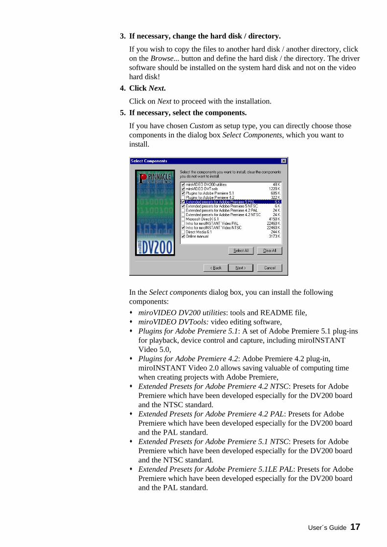
5. If necessary, select the components.
If you have chosen Custom as setup type, you can directly choose thosecomponents in the dialog box Select Components, which you want toinstall.
In the Select components dialog box, you can install the followingcomponents:
s miroVIDEO DV200 utilities: tools and README file,s miroVIDEO DVTools: video editing software,s Plugins for Adobe Premiere 5.1: A set of Adobe Premiere 5.1 plug-ins
for playback, device control and capture, including miroINSTANTVideo 5.0,
s Plugins for Adobe Premiere 4.2: Adobe Premiere 4.2 plug-in,miroINSTANT Video 2.0 allows saving valuable of computing timewhen creating projects with Adobe Premiere,
s Extended Presets for Adobe Premiere 4.2 NTSC: Presets for AdobePremiere which have been developed especially for the DV200 boardand the NTSC standard.
s Extended Presets for Adobe Premiere 4.2 PAL: Presets for AdobePremiere which have been developed especially for the DV200 boardand the PAL standard.
s Extended Presets for Adobe Premiere 5.1 NTSC: Presets for AdobePremiere which have been developed especially for the DV200 boardand the NTSC standard.
s Extended Presets for Adobe Premiere 5.1LE PAL: Presets for AdobePremiere which have been developed especially for the DV200 boardand the PAL standard.

18 miroVIDEO DV 200
s Intro for miroINSTANT Video PAL: PAL-compatible intro files foryour AVI movies, the intro movies help you switch on the VCR just intime when recording video,
s Intro for miroINSTANT Video NTSC: NTSC-compatible intro files foryour AVI movies, the intro movies help you switch on the VCR just intime when recording video,
s Microsoft Direct Media 6.x: Windows 95/98 extension (werecommend to leave this item selected).
s Online manual: This manual in PDF format and the Acrobat Reader, ifit is not already installed on your system.
After having determined the components, click Next.
This installation step is not required, if you have chosen Typical orCompact as setup type.
6. Select the video standard you use and click on Next. If you are not sure which video standard you use, please refer to theAppendix on page VII.
7. Select the directory to which you want to copy the Adobe PremierePlug-Ins and click Next.
By default, the Adobe Premiere Plug-Ins are located in the\WINAPP32\PREMIERE\PLUG-INS (Adobe Premiere 4.2LE) or\PLUG-INS (Adobe Premiere 5.1LE) folder. If this is not the case, selectyour Premiere plug-ins folder.
8. Select the directory for the intros, click Next. Select the directory into which you want to have the intros copied and
click on the Next button.
9. Choose Program Group, click Next. Choose the Program Group where you want the DV200 software to be
located (default: miroVIDEO DV200). Click on Next.
In the Start copying files window, all components you have chosen will belisted.
10.Click Next to start copying.
Now the selected components will be installed.
11.Click Finish.
If Windows requests you to restart the computer, click Finish.
After you installed the DV200 hardware and software, you can connectthe devices you use with the board.

User´s Guide 19
INSTALLING SOFTWARE FOR WINDOWS NT 4.0
1. Switch on the computer.
If you have not done so already, switch on the computer.
2. Insert CD-ROM.
If you have not done so already, insert the installation CD in your CD-ROM drive.
Under Windows NT the installation program should start automatically. If thisis not the case, the AutoStart function of your CD-ROM drive has probablybeen disabled. In this case, you have to start the installation program manually.To do so, elect the Run... command in the Start menu and enter [your driveletter]:\APP\SETUP.EXE. Click on OK to start the installation program.
The installation program is started automatically in the language specified viathe Regional Settings (Start Menu, Settings, Control Panel, RegionalSettings) of the installed Windows version.
If you use other regional settings than English, German or French, you willhave to select the language in which the installation should be carried out.
3. If necessary, change the language, click Next.
If necessary, select the language in which the installation should be carriedout.
If you have activated the German, English, or French Regional Settingsand nevertheless want to change the language of the installation program,click the button Back first and then select the language.
Click on the Next button.
This installation step is not required, if you have activated the German,English, or French Reginonal Settings.
4. Select a setup type.
In the Setup Type window, select whether you prefer a typical, a compact,or a user-defined installation.

20 miroVIDEO DV 200
s Typical: Installs all components and uses the default settings.
s Compact: Skips some components (e.g. online manual) and uses thedefault settings. You should not choose this option.
s Custom: Lets you select the components and allows to adjust thesettings individually. You should only choose this option, if severalversions of Premiere are installed on your computer, if your systemhard disk is very slow.
5. If necessary, change the hard disk / directory.
If you wish to copy the files to another hard disk / another directory, clickon the Browse... button and define the hard disk / the directory. The driversoftware should be installed on the system hard disk and not on the videohard disk!
6. Click Next.
Click on Next to proceed with the installation.
7. If necessary, select the components.
If you have chosen Custom as setup type, you can directly choose thosecomponents in the dialog box Select Components, which you want toinstall.

User´s Guide 21
In the Select components dialog box, you can install the followingcomponents:
s miroVIDEO DV200 utilities: tools and README file,s miroVIDEO DVTools: video editing software,s Plugins for Adobe Premiere 5.1: A set of Adobe Premiere 5.1 plug-ins
for playback, device control and capture, including miroINSTANTVideo 5.0,
s Plugins for Adobe Premiere 4.2: Adobe Premiere 4.2 plug-in,miroINSTANT Video 2.0 allows saving valuable of computing timewhen creating projects with Adobe Premiere,
s Extended Presets for Adobe Premiere 4.2 NTSC: Presets for AdobePremiere which have been developed especially for the DV200 boardand the NTSC standard.
s Extended Presets for Adobe Premiere 4.2PAL: Presets for AdobePremiere which have been developed especially for the DV200 boardand the PAL standard.
s Extended Presets for Adobe Premiere 5.1 NTSC: Presets for AdobePremiere which have been developed especially for the DV200 boardand the NTSC standard.
s Extended Presets for Adobe Premiere 5.1PAL: Presets for AdobePremiere which have been developed especially for the DV200 boardand the PAL standard.
s Intro for miroINSTANT Video PAL: PAL-compatible intro files foryour AVI movies, the intro movies help you switch on the VCR just intime when recording video,
s Intro for miroINSTANT Video NTSC: NTSC-compatible intro files foryour AVI movies, the intro movies help you switch on the VCR just intime when recording video,
s Microsoft Direct Media 6.x: Windows 95/98 extension (werecommend to leave this item selected).
s Online manual: This manual in PDF format and the Acrobat Reader, ifit is not already installed on your system.
After having determined the components, click Next.
This installation step is not required, if you have chosen Typical or Compactas setup type.
8. Select the video standard you use and click on Next. If you are not sure which video standard you use, please refer to theAppendix on page VII.
9. Select the directory to which you want to copy the Adobe PremierePlug-Ins and click Next.
By default, the Adobe Premiere Plug-Ins are located in the\WINAPP32\PREMIERE\PLUG-INS (Adobe Premiere 4.2LE) or\PLUG-INS (Adobe Premiere 5.1LE) folder. If this is not the case, selectyour Premiere plug-ins folder.

22 miroVIDEO DV 200
10.Select the directory for the intros, click Next. Select the directory into which you want to have the intros copied and
click on the Next button.
11.Choose Program Group, click Next. Choose the Program Group where you want the DV200 software to be
located (default: miroVIDEO DV200). Click on Next.
In the Start copying files window, all components you have chosen will belisted.
12.Click Next to start copying.
Now the selected components will be installed.
13.Click Finish.
If Windows requests you to restart the computer, click Finish.
After you installed the DV200 hardware and software, you can connectthe devices you use with the board.

User´s Guide 23
INSTALLING THE DV200 SOFTWARE LATER
In case you want to install the DV200 software or individual components forWindows 95 oder Windows NT later, proceed as follows:
1. In the Start menu, select the Run... command.
2. Insert the CD-ROM from the DV200 package contents in your CD-ROM.
3. Enter [Your CD-ROM drive letter]:\APP\SETUP.EXE.Click OK.
4. Proceed as described on page 19 as of step 2.
UNINSTALLING THE DV200 SOFTWARE AND DRIVERS
For information on how to uninstall the miroVIDEO DV200 and DVTools,refer to the ”Uninstalling miroVIDEO DV200 drivers and DVTools” chapterin the Appendix on page VI.

24 miroVIDEO DV 200
Connecting the devices
You can connect any DV video device (camcorder or VCR) with an IEEE-1394/DV connector to the DV200. You will find a list of compatible devicesin the Appendix on page VII and in the readme file.
You will find more detailed hardware connection diagrams in the Appendixas of page I.
ATTACHING A DV CAMCORDER OR A DV VCRTo connect your DV camcorder/VCR to the miroVIDEO DV200 board, usethe IEEE-1394 DV cable included in the package.
IEEE-1394 DV cable
To connect your DV camcorder/VCR to the miroVIDEO DV200 board,proceed as follows:
1. Connect the IEEE-1394 cable to the DV200 board.
Connect the 6-pin connector of the IEEE-1394 DV cable to one of thetwo external 1394 data ports of your miroVIDEO DV200 board. You canuse either data port.
Connects to theDV camcorder/VCR
Connects to themiroVIDEO DV200board

User´s Guide 25
2. Connect the IEEE-1394 cable to the DV device.
Connect the either of the 6-pin connectors of the IEEE-1394 DV cable tothe DV IN/OUT or the DV OUT connector of your DV camcorder/VCR.
CONNECTING THE TV SET/VIDEO MONITOR
To view the recorded footage, a TV set or a video monitor must be attachedto the DV camcorder/VCR. (Some camcorders have an integrated display, inwhich case you do not need to attach a video monitor.) In case you do notwant to connect a TV set or video monitor to your board, you can alwaysuse the Preview window provided with the miroVIDEO DVTools.
Video connectionsTo attach a TV set/video monitor to your DV camcorder/VCR, you need aS-Video or composite video cable.
To connect a TV set/video monitor to your camcorder/VCR:
• For S-Video monitors,connect one end of the S-Video cable to the S-Video output of yourcamcorder/VCR and the other end to the S-Video input of your videomonitor.
• For Composite video monitors,connect one end of the composite cable to the composite output of yourcamcorder/VCR and the other end to the composite video input of yourvideo monitor.

26 miroVIDEO DV 200
Audio connectionsFor the audio connections you need one audio cable for each channel.
To connect the audio cables, proceed as follows:
1. Connect the audio cables to the DV device.
Connect one end of the audio cables to the audio outputs of yourcamcorder/VCR (AUDIO OUT).
2. Connect the audio cables to your monitor.
Connect the other end to the audio inputs of your video monitor or yourTV set.
This audio connection is only required to make the sound audible, thetransfer of the audio data to the computer is done via the IEEE-1394connection.
User´s Guide 27
Working with DV material
This chapter explains how to capture a single frame from your DV tape andintroduces the step-by-step process of capturing DV clips from tape usingDVTools, editing DV using Adobe Premiere, and printing DV back to tape.The combination of the miroVIDEO DVTools and Adobe Premiere lets youget the most out of your DV footage.
Before you start working with DV material it is advisable to check yoursystem performance using the DVExpert. The DVExpert is located in themiroVIDEO DV200 Program Group. In order to provide you with realisticresults, the disk being tested should be defragmented. If you use more thanone hard disk in your system, you should test them all and use the hard diskwith the fastest data rate.For more information on the DVExpert, please click on the help button in theDVTools.
Note that the DVTools require at least a 16-bit color resolution and an 800 x600 resolution. If your display is set to fewer colors, an error message willappear after starting the DVTools. On information about how to change thecolor settings, please refer to the “Changing the number of colors and theresolution” section in the Appendix on page VII.
MAKING MOVIES
In planning and capturing your movie, use the miroVIDEO DVTools.DVTools allows you to scan the DV tape, store clip locations, view theindividual clips, re-define and edit clip in points and out points (i.e., start andend markers) and re-order clips. Once you have completed these steps, youcan create separate AVI files for each clip. After these AVIs have beencreated you can use Adobe Premiere to add titles, transitions and specialeffects. You can then output the final DV back to DV tape or—if you own amiroVIDEO DC30 (plus) board— to conventional analog tape.
The difference between scanning and capturingScanning the tape does not capture the video and save it to the hard drive.Scanning merely identifies all the clips on the tape so you can see which clipsare candidates for your final video, and which aren’t useful at all.
Capturing, on the other hand, saves the digital video on the hard drive. Atthat point, with the digital video on your computer’s hard drive, you can editthe clip using Adobe Premiere.
Neither scanning or capturing modifies your original videotape in any way.Your original shots remain in their original form and quality.
Preparations

28 miroVIDEO DV 200
Some remarks on shooting DV footageWhen shooting DV, you can use as many DV tapes as you like. DVTools iscapable of keeping track of as many DV tapes as you wish to scan. Whenyou scan the video tape later, the software will automatically detect the startof a clip at each place where you started the recorder. Conversely, thoseplaces where you stopped recording will automatically be detected as ends ofclips.
When shooting video footage, make sure the camcorder is running inCamera mode.
Checking preferences in miroVIDEO DVToolsBefore using the miroVIDEO DVTools to capture your video footage, it isadvisable to check the preferences with regard to your television standardand some recording parameters. In Western Europe (except for France), thePAL standard is used; the standard used in the USA is NTSC. For details ontelevision standards, see the p. VII in the Appendix.
To check the preferences in the miroVIDEO DVTools, proceed as follows:
1. Launch the miroVIDEO DVTools.
Click Program Files in the Start menu. Select the program groupmiroVIDEO DV200 and click on miroVIDEO DVTools.
The Capture Gallery appears.

User´s Guide 29
3. Checking the TV standard.
In the Capture Gallery, select the Tools menu and the Preferences menuitem. This dialog will be displayed the first time you launch DVTools. Theprogram can automatically detect the video standard if the DV device isconnected to the card and is switched on. You must not overwrite thissetting.
3. Choose your preferred capture method
You can select between a single pass capture and a multi pass capture.Default is single pass capture since your PC system should be fast enoughto capture DV footage in one pass. If you find too many dropped frameson the capture you might select the multi pass capture method.
4. Select the capture drive.
Under Trim point based capture, select the hard drive and the directorywhere you want to save the video. Please verify that enough storage spaceis available on this drive.
5. Select the audio channel.
DV devices support two audio channels on a 32kHz setting. Select thechannel from which you want to capture the sound.
6. Select an appropriate value for the Length of blank. Click OK.
When scanning a DV tape containing long blank sections where no DVfootage has been recorded, the DVTools might abort the scanning processin the middle of such a pause because it assumes that the blank section isthe end of the recording. To ensure that the DVTools continue to scan thetape, you can enter a value (in seconds) under Length of blank. This valuedetermines the maximum length of a blank section which the DVToolswill accept as a pause but not as the end of a recording.

30 miroVIDEO DV 200
Scanning a DV tape for clipsOnce you have set the preferences, you can use miroVIDEO DVTools toscan your DV tape(s) for clips. A clip is defined as a video sequence locatedbetween an in point (start of take) and an out point (end of take).
To scan a DV tape for clips, proceed as follows:
1. Connect DV equipment.
If you haven't already, connect your DV camcorder or DV video recorderto the miroVIDEO DV200 board. For instructions, see the chapter„Connecting the devices“ on page 24 and the Appendix on page I.
2. Turn on your DV equipment.
Turn on your DV camcorder or DV video recorder. Make sure that yourDV camcorder is running in VTR mode.
3. Insert DV tape.
If you haven't already, insert the DV tape in your DV equipment.
4. Scan DV tape.You can start the scanning process in three ways:s Click the Tape Scan button in the right section of the Capture Gallery
(see icon).
s Right-click into the DV Explorer (mainly white area in the left sectionof the Capture Gallery) and select Scan DV tape...
s From the Tools menu, select Scan DV tape.
It is also possible to scan the tape manually (Live capture) and capture thevideo simultaneously. For information on the Live Capture, refer to page53.
The DV tape is then rewound to the beginning and the DVTools display adialog box showing the progress of the scanning process. To abort thisprocess, click on Cancel.
5. Enter a name and description for the DV tape or rescan the tape.
After the tape has been rewound, DVTools will identify the tape.
s If the tape is unknown to the tape database, the program will promptyou to enter a name and a description for the tape. After you havetyped in the information, the tape description will be stored in thedatabase.
s If the tape is already known, the program will allow you to abort thetape scan or to rescan the tape. The clips from the previous scan areremembered and you will be promoted as to where to start the newscan. This is helpful if you have recorded new footage to a tape youhave previously scanned. You can scan in the new scenes, updating theexisting scan gallery, without having to re-scan the entire tape.
Next, DVTools scans the DV tape for clips. The scan process takes asmuch time as it would take to play back the video footage on your tape.For example, a 30-minute tape will take approximately 30 minutes to bescanned if the tape is completely filled with video information. If the tape

User´s Guide 31
only contains 15 minutes of video data the scan will need approx. 15minutes.
Once the software has finished scanning the tape, a window appears inwhich all the clips found on the video tape are depicted as „poster frames“(the first frame in a clip). This Tape Gallery will be brought up any timeafter you scanned a tape.
6. Scan additional DV tapes if necessary.
If you want to use several video tapes for your movie, have DVTools scanfor clips as described above.
Viewing clips and adding trimsTo view your DV at full-screen size, a television set or video monitor mustbe connected to your DV camcorder or DV video recorder (see p. 24). Thereis also a preview window in the DV Device Controller that plays back yourDV in a small thumbnail window with a reduced resolution.
To view clips, proceed as follows:
1. Open DV tape (if necessary).If the Tape Gallery with the clips of your video tape is not displayedalready, double-click a database name in the DV Explorer. The tape inquestion must be in the DV camcorder.
A Tape Gallery then appears in which all the clips on your video tape aredepicted by the first frame (poster frame) of each clip.
3. Playing back clips.
To view a clip, first double-click on the desired clip. The Clip Infowindow will then appear.

32 miroVIDEO DV 200
The Clip Info window displays the title, the time code, and the trim points(if there are any). If you wish to do so, you can enter a description foryour clip.
To rewind or forward the tape to the position where the clip is located,click on the (eye) button. The DV device will take a while to find thestart of the clip.
The DV Device Controller will appear. You will know that the tape ispositioned to the start of the clip when the time code displayed at the topof the window is identical with the clip start displayed at the bottom of thewindow.

User´s Guide 33
The DV Device Controller lets you control your DV device. The videotape does not automatically stop when it reaches the end of a clip. Topause the playback, click on the Pause button. For a detailed descriptionof the DV Device Controller, see p. 45.
3. Choose the clips you want to capture.
Once you have „sifted through“ your video footage, you can choose theclips you actually want to capture. To do so, drag the desired clips fromthe Tape Gallery and drop them in the Capture Gallery*. You can arrangethe clips in the Capture Gallery in any order.
4. Add trims.
Sometimes you may not want to use an entire clip, but rather only part ofa clip. In that case, you can edit the clip in question using the DV DeviceController.You can define the in point and out point of a clip using the (in point)and (out point) buttons. You can either click on the buttons duringplayback, or pause the tape at the desired location and then click on thesebuttons. You can also forward and rewind the tape using the slider control
* Drag & Drop:
Left-click the desired element. Hold the mouse button down and drag the element to the desired position. To„drop“ the element, release the mouse button.

34 miroVIDEO DV 200
at the bottom of the DV Device Controller window (jog-shuttle function).
Once you have finished inserting the points in the clip, click (Apply) to save the trim points.
The original trim points are still stored in the clip database and can be
restored at any time by clicking on .
6. Save the Capture Gallery file.
Save the Capture Gallery file with the added clips and edits. To do so,select the Save as... option in the File menu. These files are saved with theextension *.sto.
Capturing DV (generating AVI files)Now that you have selected the clips for your movie, you can generate AVIfiles.
To generate AVI files from the clips, proceed as follows:
1. Open the Capture Gallery.
If you have not done so already, open the Capture Gallery you want tocapture. To do so, click on the File menu in the DVTools and select OpenCapture Gallery. Here you can select the Capture Gallery (*.sto file).
2. Check file size.
The status bar at the bottom of the Capture Gallery shows the clip count,the total duration, and the total size of the AVI files that will be generated.If you like to verify that you have enough disk space for capturing theclips from this Gallery, click on your drive in Windows 95 Explorer. Thefree space on your hard disk will be displayed. However, DVTools willcheck if there is enough disk space available before capturing.

User´s Guide 35
3. Capture AVI files.To create AVI files from the clips in your Capture Gallery, click theCapture button located on the right-hand side of the Capture Gallery.
4. Enter file name and directory.
If you do not want to use the default drive you chose in the Preferencesdialog, enter a file name and choose a directory to which you want tocopy the AVI files. All clips located in the Capture Gallery will then becaptured. The AVI files will be numbered according to the order ofcapturing.
DVTools use a unique technology, in multi-pass capture mode, allowinglossless capture also on slower computer systems. For that reason, DVToolsmay search the DV tape one or more times to retrieve dropped frames.
Editing AVI files using Adobe PremiereThe DVTools allow you to directly launch Adobe Premiere without havingto do this from the Windows Start menu.
If you want to output your AVI file to the miroVIDEO DC30 board, youmust select the Optimized display for miroVIDEO DC30 option in the DVConfiguration tool.For more information on this tool, please refer to page 50.
To edit your AVI file(s) using Adobe Premiere, proceed as follows:
1. Start Adobe Premiere.To start Adobe Premiere, click on the corresponding button on the right-hand side in the Capture Gallery. (If Adobe Premiere is not installed onyour system, this button will be disabled.)
2. Select a Project Preset.
Select an appropriate Project Preset, depending on whether you are usingPAL or NTSC and on whether you want to output your final DV file to aDV tape or to an analog video tape via miroVIDEO DC30.For more information on the Project Presets, refer to page 53.
3. Import AVI file(s).
To import one or more AVI files, go to the File menu and select the menucommands Import and File... . Select the AVI file(s).
4. Edit AVI file(s).
At this point you can add effects and process your video. If necessary,select the display mode for all frames of the video clips under Windows,Construction window options, Track format.
5. Select output options.
In Adobe Premiere, select Make, Output Options. Under Type, selectFull Size Frame.
36 miroVIDEO DV 200
6. Make a movie.
To make a movie, select the menu command Export Movie in theFile/Export menu. Specify the proper compression (predefined in theProject Preset).
Instead of using the Export Moviee command and print the DV to tape usingthe DVTools, you can also use the miroINSTANT Video tool to create yourfinal movie and to save it back to the DV tape. For more information onmiroINSTANT Video, please refer to the “miroVIDEO DC200 & AdobePremiere 4.2LE” chapter as of page 53 or the “miroVIDEO DC200 &Adobe Premiere 5.1LE” chapter as of page 61.
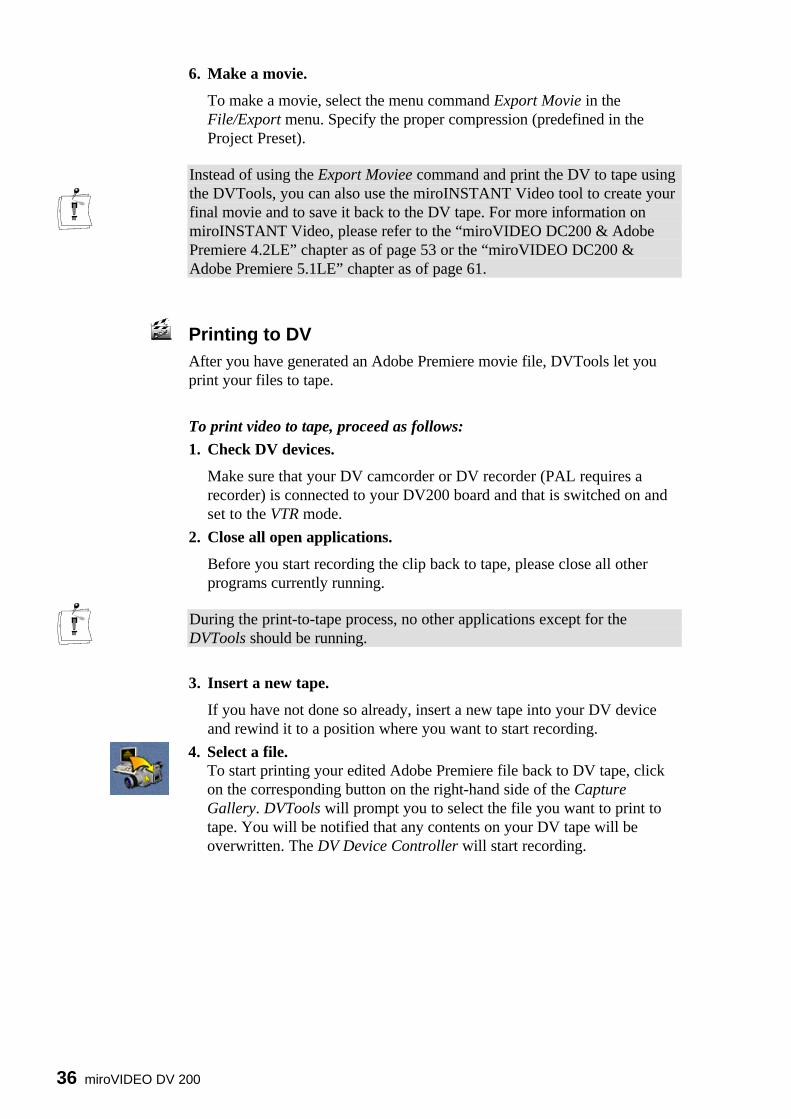
Printing to DVAfter you have generated an Adobe Premiere movie file, DVTools let youprint your files to tape.
To print video to tape, proceed as follows:
1. Check DV devices.
Make sure that your DV camcorder or DV recorder (PAL requires arecorder) is connected to your DV200 board and that is switched on andset to the VTR mode.
2. Close all open applications.
Before you start recording the clip back to tape, please close all otherprograms currently running.
During the print-to-tape process, no other applications except for theDVTools should be running.
3. Insert a new tape.
If you have not done so already, insert a new tape into your DV deviceand rewind it to a position where you want to start recording.
4. Select a file.To start printing your edited Adobe Premiere file back to DV tape, clickon the corresponding button on the right-hand side of the CaptureGallery. DVTools will prompt you to select the file you want to print totape. You will be notified that any contents on your DV tape will beoverwritten. The DV Device Controller will start recording.

User´s Guide 37
CAPTURING SINGLE FRAMES (SNAPSHOTS)The miroVIDEO DVTools allow you to capture still images with the DVrecorder, the camcorder in VTR mode or directly from its lens.
Checking preferences in miroVIDEO DVToolsBefore using the miroVIDEO DVTools to capture single frames from yourvideo footage, it is advisable to check the preferences with regard to yourtelevision standard and the frame size.
To check the preferences in the miroVIDEO DVTools, proceed as follows:
1. Open the miroVIDEO DVTools.
Click Program Files in the Start menu. Select the program groupmiroVIDEO DV200 and click on miroVIDEO DVTools.
2. Checking the TV standard.
In the Capture Gallery, select the Tools menu item...
... and the Preferences menu item.

38 miroVIDEO DV 200
The DV data format will be autodetected at any time while DVTools isrunning. You must not overwrite the setting.
4. Select an image size for your BMP file.
From the Snapshot list box select the size you want your frame to have.The table below states the BMP resolutions that will result from thedifferent settings.
Setting NTSC PALFull size 720 x 480 (full TV size) 720x576Quarter size 360x240 360x2881/16 size 180x120 180x144
If you want to de-interlace your bitmaps, select the De-interlace option.Click on OK. (For more information on the De-interlace feature, read the„De-interlace“ section at the end of this chapter).
Capturing single framesOnce you have set the preferences, you can use the DVTools devicecontroller to capture a single frame from either recorded video footage ordirectly from the lens.
To capture a single frame, proceed as follows:
1. Connect DV equipment.
If you haven't already, connect your DV camcorder or DV video recorderto the miroVIDEO DV200 board. For instructions, see the chapter„Connecting the devices“ on p.24 and the Appendix as of page I.
2. Turn on your DV equipment.
Turn on your DV camcorder or DV video recorder. If you want tocapture a single frame from your recorded video footage, make sure thatyour DV camcorder is running in VTR mode and that a suitable tape hasbeen inserted.
If you wish to capture a single frame directly from the lens, set yourcamcorder to the Camera mode and point it at the object you wish tocapture.
3. Open the DV Device Controller.
To open the DV Device Controller, click on the (camera) icon in theDVTools window.
4. Create bitmap.
If you are running in the VTR mode, search out the frame you would liketo capture using the transport controls and click on the Pause button tostop the tape.
Click on the (snapshot) button to temporarily store the image toRAM.

User´s Guide 39
5. Name and save the BMP file.
You can now enter a name and a location where you like to save yourBMP file.
De-interlacingThe DV200 software automatically de-interlaces the images you capturefrom your DV tape. TV systems, such as NTSC and PAL use the interlacingtechnique.
TV images are not scanned (drawn) line by line, but first all odd lines (1, 3, 5etc.) are drawn and in a second step all even lines (2, 4, 6 etc.) are drawn.The sections consisting of either odd or even lines are called fields.
When watching TV the human eye cannot distinguish the odd and the evenlines but merges them so that they appear as one. When capturing a DVimage, however, the resulting image would normally look distorted becausethe odd and the even frames are put together.
The DV200 software, however, compensates for this with the feature calledde-interlacing by eliminating one field and generating a new enhanced imagefrom the remaining field.

40 miroVIDEO DV 200
miroVIDEO DVTools
This chapter describes miroVIDEO DVTools in detail.
miroDVTools let you scan for clips on your DV tape, add in and out points,control your DV devices, transfer DV to your hard disk and back to DVtape.
miroVIDEO DVTools consists of three main components: the CaptureGallery, the Tape Gallery, and the DV Device Controller.
CAPTURE GALLERY
The most important workspace in the miroVIDEO DVTools is the CaptureGallery. Here you can arrange the clips you want to capture, check therunning time and file size of a movie, generate AVI files, open AdobePremiere, and print AVI files back to tape.
To access the Capture Gallery,
• select Program Files from the Start menu. Select the miroVIDEO DV200program group and click miroVIDEO DVTools.
The Capture Gallery opens.
The Capture Gallery consists of the menu bar, the tool bar, DV Explorer,the film strip, the DV buttons and the status bar. The following sectionsexplain these individual components.

User´s Guide 41
Menu bar New Capture Gallery:Lets you create a new Capture Gallery database. Capture Gallery databaseshave the file extension *.sto.
Open Capture Gallery:Lets you open an existing Capture Gallery.
Save Capture Gallery:Lets you save the Capture Gallery database which is currently open.
Save Capture Gallery as:Lets you save the database which is currently open under another name.
Last Capture Gallery:Opens the Capture Gallery that has been saved last.
Exit:Exits the DVTools.
Add clips to Capture gallery: Allows you to manually define clip segments to be added to the CaptureGallery. Useful when working with tapes that have very large or just onescene (recorded with no interuption for the entire tape).Thumbnails:Toggles between the Clip Gallery and an overview window. If you enableThumbnails, you can view more clips which provides a better overview.
Clip Info:The Clip Info window displays the title and the description of the clip, thetime code, and the trim points (if there are any). It also contains the Playbutton (eye).
Rename DV tape database:Lets you rename an existing database. To rename an existing database, clickon a database in the DV Explorer, select Rename DV database and enter anew name.
Delete DV tape database:To remove an existing database, click on a database in the DV Explorer,select Delete DV tape database.
Options:When clicking on Options, the following dialog appears:
File menu
View menu

42 miroVIDEO DV 200
To select another language for the DVTools, you can choose the languageyou prefer from the list box.When enabling Force confirmation on file deletions, you will be prompted toconfirm that you want to delete the file every time you want to remove adatabase. Disabling this option avoids this request.The Use Tool Tips option check box lets you toggle the little informationwindows that appear for the buttons.
DV Device Controller:Opens the DV Device Controller. For detailed information on the DV DeviceController, please refer to page 45.
Scan DV tape:Lets you scan a tape and create a New database. Instead of this menu item,you can also use the Scan Tape button located on the right-hand side in theCapture Gallery. For more information on scanning DV tapes please refer tothe section ”Scanning a DV tape for clips” on page 30.
Seek start of clip:When clicking on a clip in the Clip Gallery, the DV Device Control will beopened and the device will rewind the tape to the start of the clip.
Capture Scenes From Capture Gallery:Use the Capture command to start capturing (transferring the DV clips to thehard disk) the clips you inserted in the Capture Gallery. Instead of this menuitem, you can also use the Capture button located on the right-hand side inthe Capture Gallery.
Start Video Editing Application:Launches Adobe Premiere.
Print-to-DV-tape:Use the Print-to-DV-tape command to start playing back the AVI clips backto tape. Instead of this menu item, you can also use the Print-to-tape buttonlocated on the right-hand side in the Capture Gallery. For more informationon recording your clips back to the DV tape, please refer to the ”Printing toDV” section on p. 36.
Please note: You must always capture the clips, which means transferringthem to your hard disk and converting them into AVI files, before you canrecord them back to your DV tape. It is not possible to scan a tape, arrangesome clips in the Capture Gallery and print them back to the DV tape.
Preferences:Opens the Preferences dialog box. For more information on the Preferencesdialog box, refer to the ”Checking preferences in miroVIDEO DVTools”section on page 28.
Tools menu

User´s Guide 43
Tool bar The toolbar provides quick access to the following dialog boxes andwindows:
Saves the current Capture Gallery.
Opens the DV Device Controller.
Only appear when there are scenes in the Capture Gallery
Show all clips in the Capture Gallery.
Manually add/remove clips in Capture Gallery.
Rewinds/fast forwards the tape to the start of the current clip.
Opens the Clip Info window.
DV Explorer The DV Explorer has the look-and-feel of the Windows Explorer andprovides a clear overview over the DV tapes you have already scanned. Afteryou have scanned a DV tape, the DVTools will prompt you to enter a namefor the database. This name will then appear in the DV Explorer. The actualdirectory with the media database files (*.sbd) is located on your hard disk inthe DV200 directory, which is by default DV200/DVTools/Media.
To delete or rename the databases, select the Delete database or Renamedatabase commands from the View menu.
Always present
Opens a new Capture Gallery.
Opens an existing Capture Gallery.

44 miroVIDEO DV 200
Film strip In the film strip you can arrange the clips you want to capture (as the nameCapture Gallery infers) by moving them from a Tape Gallery to a film stripframe. To insert a clip from the Tape Gallery into one frame of a film strip,click on the clip, hold the mouse button down, drag the element to thedesired position, and release the mouse button. To insert a clip, drag anddrop it between two existing clips.
You can also replace the clip which has already been inserted into the filmstrip by dragging the desired one directly on top the one to be replaced.
DV buttons
The DV buttons provide the basic functions of the DV Tools.
Tape Scan (New DV tape database):Lets you scan a tape and create a New database. For more information onscanning DV tapes, please refer to the section “Scanning a DV tape for clips”on page 30.Capture scenes from Capture Gallery:Use the Capture command to start capturing (transferring the DV clips to thehard disk).Start Video Editing Application:Launches Adobe Premiere. Print to DV tape:Use the Print to DV tape command to start recording the AVI clips. Formore information on recording your clips back to the DV tape, please referto the “Printing to DV” section on p. 36.
Status bar
The status bar shows the number of clips inserted in the Capture Gallery aswell as the running time and the expected file size.
The running time states the total duration of all clips which have beeninserted into the Capture Gallery in time code format(hours:minutes:seconds:frames).
The expected file size states the sum of the file sizes (in MB) which willresult after you have captured the clips from the Capture Gallery.
User´s Guide 45
TAPE GALLERY
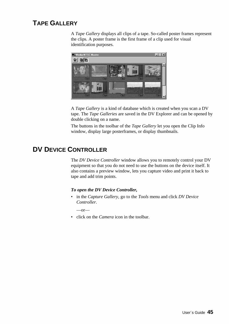
A Tape Gallery displays all clips of a tape. So-called poster frames representthe clips. A poster frame is the first frame of a clip used for visualidentification purposes.
A Tape Gallery is a kind of database which is created when you scan a DVtape. The Tape Galleries are saved in the DV Explorer and can be opened bydouble clicking on a name.
The buttons in the toolbar of the Tape Gallery let you open the Clip Infowindow, display large posterframes, or display thumbnails.
DV DEVICE CONTROLLER
The DV Device Controller window allows you to remotely control your DVequipment so that you do not need to use the buttons on the device itself. Italso contains a preview window, lets you capture video and print it back totape and add trim points.
To open the DV Device Controller,
• in the Capture Gallery, go to the Tools menu and click DV DeviceController.
—or—
• click on the Camera icon in the toolbar.
46 miroVIDEO DV 200
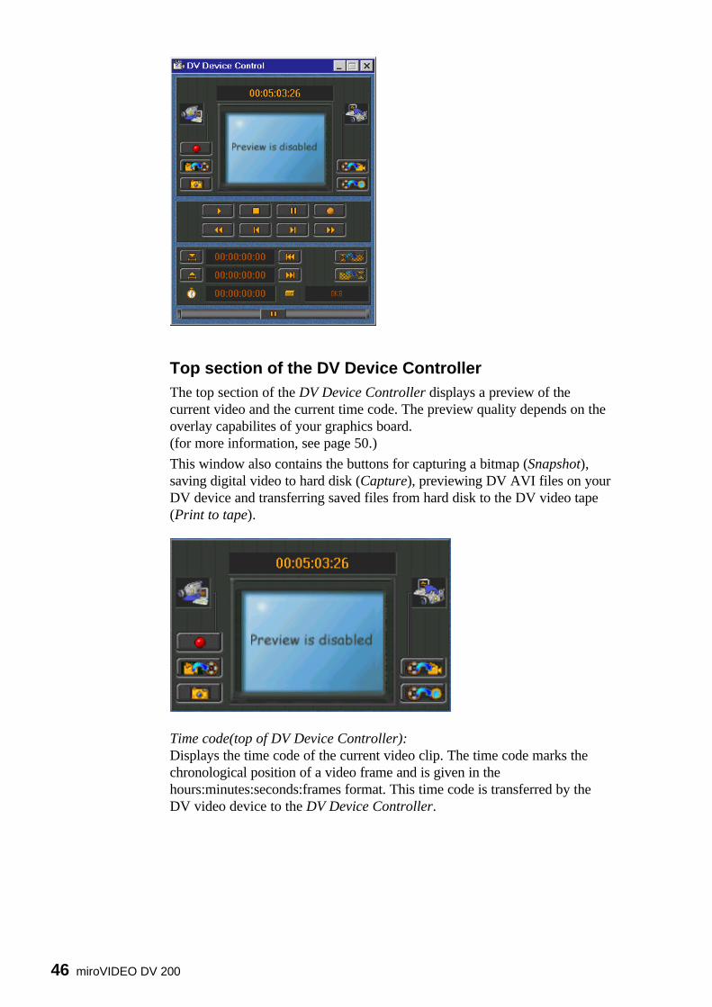
Top section of the DV Device Controller The top section of the DV Device Controller displays a preview of thecurrent video and the current time code. The preview quality depends on theoverlay capabilites of your graphics board.(for more information, see page 50.)
This window also contains the buttons for capturing a bitmap (Snapshot),saving digital video to hard disk (Capture), previewing DV AVI files on yourDV device and transferring saved files from hard disk to the DV video tape(Print to tape).
Time code(top of DV Device Controller):Displays the time code of the current video clip. The time code marks thechronological position of a video frame and is given in thehours:minutes:seconds:frames format. This time code is transferred by theDV video device to the DV Device Controller.

User´s Guide 47
From DV Device to Computer(Left Side)Live capture:The Live capture button lets you capture video directly from the lens or fromyour DV tape. If you want to capture video from the lens of your DVcamcorder, make sure that it is set to the Camera mode.
If you want to capture video from the tape, make sure that your DV device isset to the VTR mode.
After you start capturing, a dialog box appears displaying the progress of thecapture process. To abort capturing, press the Cancel button. If you do notabort capturing manually, the DVTools will save DV video to your hard diskas long as enough storage capacity is available. After the capturing process iscomplete, you can enter a drive and the directory where you want to save theAVI file. The default drive is the one you selected, in the Preferences dialogbox (see page 36).
Capture (creating AVI file):This button lets you create an AVI file from the current video clip. You canonly use this button after you set the in and out points for the clip boundaries(like during tape scan). If you did not scan the tape and you want to capturean AVI file from your tape, use the Live capture button (see below). If youdo not want to save the entire clip on the hard disk, you may want to set trimpoints. These trim points mark the beginning and the end of the AVI file.(See also the “Capturing” section on page 53.)
From Computer to DV Device(Right Side) Preview DV Output:This button allows you to play back an AVI file to your DV device forpreviewing. Print-to-tape (recording AVI files back to the DV videotape):Allows you to save the AVI file back to your DV videotape.
VTR controls The VTR controls area lets you remotely control your DV device. Thecontrols resemble the controls found on your DV device.
Playback:The DV device plays back the tape.Pause:The DV device stops playing back the tape, while displaying the currentframe.Stop:The DV device stops playing back the tape, the current frame will not bedisplayed.

48 miroVIDEO DV 200
Set To Record:Allows you to set the DV device to record. Useful for e.g. PAL cameras thatdo not have a record button for use in VTR mode.
Rewind/Play fast in reverse:If the DV device is stopped, this button rewinds it rapidly. If the DV deviceis in play or pause mode, this will provide fast reverse play with viewablevideo.Step back:This button lets you jump to the previous frame.Step forward:This key lets you jump to the next frame.Fast-forward/Play fast forward:If the DV device is stopped, this button causes the tape to move forwardrapidly. If the DV device is in play or pause mode, this will provide fastforward play with viewable video.
Trim points If you do not want to capture the entire clip but only a section of it you maywant to define trim points (in and out points). It is only possible to add trimpoints, if you scanned the tape. A clip is in this case the video footagebetween the start of a shot and the end of a shot.
You cannot define sections extending beyond clip boundaries when youopened the DV Device Control from within the Clip Info window.
These buttons let you define in and out points to define the start and end of asection. Click on these buttons either during playback or in the pause mode.You may also use the slider at the bottom of the DV Device Controller (jogshuttle) to move the tape forward or to rewind it. Start of clip:Rewinds the current video clip to its beginning. End of clip:Moves the current video clip forward to its end. Apply trims:After you defined a section, click Apply trims.

User´s Guide 49
Manual editing of the In and Out time codeThe DVTools DV Device Controller allows for the manual (typed) entry oftrim point timecode by the user. Simply double click on either the In or Outpoint time code window to bring up the Manual trim point entry window.Enter in the desired trim In and/or Out point value and then click OK.
The trims will only be permanently saved in the clip using the Apply trimsbutton, if the videotape has already been scanned and if a database has beencreated for it.If you add trims in a clip you opened from the Tape Gallery, these trims willbe permanently saved for this clip until you change them.If you add trims in a clip you opened from the Capture Gallery, the trimswill only be saved for this special Capture Gallery database.
The Clip length is the duration of the current section. If no trim points wereset, the duration of the whole clip will be displayed.
The File size displays the file size (in kilobytes) the current section will havewhen being captured. If no trim points were set, the size of the whole clipwill be displayed.
You may delete the trims you set in the current clip by clicking the Deletetrims section. This restores the original clip boundaries.
Jog-Shuttle
The Jog/Shuttle slider is located at the bottom of the DV Device Controllerwindow. You can use it to search through a tape at different speeds toaccurately locate start and end frames for your clips. The Jog/Shuttle sliderduplicates the Jog/Shuttle editing wheels offered on VCRs. The rewind andfast forward modes of the VTR controls scan in one speed, whereas theJog/Shuttle slider offers a variety of speeds.
When the slider is in the middle, the DV device is paused. Dragging thecontrol box to the left accesses the reverse shuttle speeds, while dragging itto the right accesses the forward shuttle speed.
Not all DV devices support all of the functions possible with the DVToolsDV device controller. Please refer to your DV device's owner's manual tolearn what functions your DV device supports.

50 miroVIDEO DV 200
Manually inserting video clips into the Capture Gallery.
The DV Tools identify recorded scenes on a registered DV Video tape bydate and time code information. Using the View menu and the command Addclips to capture gallery the user is able to insert a video clip into the currentCapture Gallery.
Determine the tape you wish to capture the footage from (Current tape reliesto the tape which is currently in your powered camcorder). Click on the New( ) button. Set the in and out point. Click on Apply. If necessary, definefurther video clips. Click on Add in order to add the clips to the CaptureGallery. The window Add clips to capture gallery supplies the commandsNew, Rename and Delete. You can access them using the buttons in theupper left corner or by clicking right into the editing area.
Rescanning tapes
If a tape has already been scanned before, the DV Tools will offer to rescan thetape from the beginning or from any known clip. You can add footage to the DVtape without effecting existing clips stored in the database. Select the clip youwould like to start from using the corresponding list box.

User´s Guide 51
miroINSTANT VIDEO PLAYBACK
miroVIDEO DV200 Configuration The miroVIDEO DV200 Configuration allows you to enable/disable options
s for using the DV200 with the miroVIDEO DC30 series board,s for the display of the DV video, ands for outputting the video via miroINSTANT Video on your computer
monitor. The miroVIDEO DV200 Configuration tool is located in themiroVIDEO DV200 Program Group.
By default, the Use Direct Draw Overlay Surface and the Use Direct DrawOverlay Surface optios are enabled. The other options are disabled.
To exit the Configuration, click Close. If you changed the settings, thechanges will not be saved when clicking Close.
If you want to save the settings, click Save.
Optimized Display for miroVIDEO DC 30 If you want to record the DV video clips you captured with the DV200board back to an analog video tape via the miroVIDEO DC30 (plus) boardor if you want to convert already existing DC30 clips inot the DV formatusing Adobe Premiere, please select theOptimized Display for miroVIDEO DC 30 option.
Use Direct Draw Primary SurfaceTo enhance the preview quality and the display quality in the Media Player,you may want to enable the Use Direct Draw Primary Surface option. Touse this option, however, your graphics board has to support DirectDraw. Ingeneral, state-of-the-art PCI graphics boards support an Overlay Surface.For more information on the DirectDraw support, please refer to the manualof your graphics board.
52 miroVIDEO DV 200
If your graphics board does not support the Direct Draw Primary Surfaceand the option is enabled, the video will be displayed on your computermonitor but at a lower image refresh rate.
Use Direct Draw Overlay Surface The DVTools provide a preview function which displays the video suppliedby your DV device or AVI files in a small window on your computermonitor. You can also playback the AVI files created with the miroVIDEODV200 board using the Media Player.
To enhance the preview quality and the display quality in the Media Player,you may want to enable the Use Direct Draw Overlay Surface option. Touse this option, however, your graphics board has to support DirectDraw. Ingeneral, state-of-the-art PCI graphics boards with e.g. S3 Trio64 V+, Virge,or Virge VX graphics processors support an Overlay Surface. For moreinformation on the DirectDraw support, please refer to the manual of yourgraphics board.
If your graphics board does not support the overlay function and the optionis enabled, the video will still be displayed on your computer monitor albeit ata lower image refresh rate.
If your graphics board supports Direct Draw but no overlay or a distortedoverlay appears, it may be for the following reasons:
s The overlay does not work at the current display resolution. If this is thecase, try out another resolution and select a smaller number of colors. Inthis case, close the window displaying the video and select anotherresolution and another color depth.
s The graphics board's drivers does not support the overlay feature. Pleaseinstall the latest drivers for your graphics board.
It will not be readily apparent whether your graphics board supports overlayor not.
To test whether your graphics board supports the overlay feature orwhether it does not, you can perform a simple test.
1. Make a screenshot of the window displaying your video by pressing the<Alt> and the <Print> keys on your keyboard. The window containing thevideo (DV Device Controller or Media Player) must be the active one.
2. Open an image application e.g. Paint from the Windows Program GroupAccessories.
3. From the Edit menu, select the Paste command.
If the video image looks like the one you captured, your graphics board doesnot support overlay.
If a magenta-colored area appears, your graphics board does support anoverlay.
Display output on PC monitorEnable this option if you want to output DV files on your computer monitorwhich you created using miroINSTANT Video under Adobe Premiere.
Testing theoverlay feature

User´s Guide 53
miroVIDEO DV200 &Adobe Premiere 4.2LE
ADOBE PREMIERE PROJECT PRESETS
In order to create a project in Adobe Premiere, you must first select a ProjectPreset. By selecting a Project Preset, you select the preview and outputoptions for your movie.
After you start Adobe Premiere, the New Project Presets window opens.
The following Presets are offered:
DV200 NTSC -> DV200 NTSC:Select this Project Preset if you use the NTSC standard and you want torecord the video files you captured and edited back to DV tape.
DV200 PAL -> DV200 PAL:Select this Project Preset if you use the PAL standard and you want torecord the video files you captured and edited back to DV tape.
DV200 NTSC ->DC30 NTSC (720x480):Select this Project Preset if you use the NTSC television standard and youwant to record your AVI files back to an analog video tape via themiroVIDEO DC30 board. Your movie will be built with a resolution of720 x 480 (corresponds to the studio standard CCIR 601). The horizontalresolution is more precise than in the straight NTSC resolution (640 x 480)and no time-consuming recomputation is required. The disadvantage ofrecording video with this setting is that it will be slightly distorted whenbeing displayed on the computer screen, e.g., circles are not depicted ascircular.

54 miroVIDEO DV 200
DV NTSC -> DC30 NTSC 4:3 (640 x 480):Select this Project Preset if you use the NTSC television standard and youwant to record your AVI files back to an analog video tape via themiroVIDEO DC30 board. Your movie will be built with the strict NTSCresolution of 640 x 480. With this Preset, square pixels are generated, i.e.,the image will not be distorted on the computer screen. The disadvantage ofthis setting is lengthy recomputation time when building a movie.
DV200 -> DC30 PAL (720 x 576):Select this Project Preset if you use the PAL television standard and youwant to record your AVI files back to an analog video tape via themiroVIDEO DC30 board. Your movie will be built with a resolution of 720x 576 (corresponds to the studio standard CCIR 601). No time-consumingrecomputation is required when building a movie. The disadvantage of thissetting is slight distortion on the computer screen, e.g., circles are notdepicted as circular.
DV200 -> DC30 PAL 4:3 (768 x 576):Select this Project Preset if you use the PAL television standard and youwant to record your AVI files back to an analog video tape via themiroVIDEO DC30 board. Your movie will be built at the strict PALresolution of 768 x 576. With this Preset, square pixels are generated, i.e.,the image is not distorted on the computer screen. The disadvantage of thissetting is lengthy recomputation time when building a movie.
THUMBNAIL ACCELERATION
In Adobe Premiere, display of thumbnails is accelerated. For a flickerlessdisplay in the preview, select the resolution 200 x 135 (NTSC) or 200 x 160(PAL) for the preview mode.
In PAL, some image sizes may form black stripes on the right and leftedges of the image. These stripes have no effect on your finished movie,since they are not in the viewable area.

User´s Guide 55
miroINSTANT VIDEO 2.0
General
miroINSTANT Video accelerates video productions providing smart andpowerful functions to edit, preview and print-to-tape of DV encodedmaterial. Complete productions can be recorded back to tape selecting theSynchronous start option.
In the past, in order to output your project or to get a high-quality preview,you had to ”make a movie”. During this time-consuming process, the editingapplication would copy all of your source material into a new AVI file. Thiswould happen not only for the areas where you applied an effect or atransition, but for the entire length of your production. Not only did thistake a considerable amount of time, but it also requires the same amount ofdisk space as the clips you already captured. In addition, your output waslimited to a maximum size of 2 GB (2048 MB) because of a restriction ofVideo for Windows.
miroINSTANT Video changes all of this. Instead of ”making a movie”, youmay now invoke miroINSTANT Video, which will scan through your projectand create AVI files only for the areas where you applied effects ortransitions. This is—depending on the complexity of your project—up totwenty times faster and will not waste disk space by copying material that hasnot been modified.
But miroINSTANT Video goes even further—it will play back the resultingrange of AVI files automatically and seamlessly right from the constructionwindow timeline by automatically accessing the miroAVI Cache. Thus, thefact that you did not ”make a movie” is totally transparent. miroINSTANTVideo does not require that you keep track of the separate AVI files, it doesit for you.
Even better, with miroINSTANT Video, your production may be as long asyour disk space allows (up to the 60 minute limit of Adobe Premiere). Asthere is no one file that everything is being copied to, there is also no 2GBlimitation.
In most cases, the miroINSTANT Video plug-in should be installed on yoursystem. If not, you deselected the miroINSTANT Video option in theinstaller. If this is the case and you want to install miroINSTANT Videonow, see the “Installing the DV200 software later” chapter on page 22.

56 miroVIDEO DV 200
Using miroINSTANT Video 2.0
miroINSTANT VIDEO lets you do either of two things:
s You can preview your project on your PC monitor or a connected DVdevice.
s You can record your project to DV tape.If you do not want to record your project to DV tape but just want to have alook at the preview, use the DV200 Configuration tool to select the Previewoption. The DV200 Configuration tool is located in the DV200 ProgramGroup.
To use miroINSTANT Video in Adobe Premiere, just do the following:
1. After you launched Adobe Premiere, select a suitable Project Preset (seep. 53).
2. Create an Adobe Premiere Project. Open the AVI files you want toinclude in your project. Edit your project. For further information onAdobe Premiere, please refer to the Adobe Premiere documentation.
3. After you finished editing, save your project.
4. From the Make menu, select Output Options and Full Size Frame.
Before using miroINSTANT Video, it is required to save the project file.Always select the Full Size Frame option in the Output Option dialog!
5. To make your movie, click on the File menu and select Export.
6. Select miroINSTANT Video.

User´s Guide 57
7. If you want to preview your project, click on the button.
If you want to record your project to DV tape, make sure that your DVdevice is set to the VTR mode and that you inserted a new DV tape.Enable the Intro option from the menu. To start recording, click the button in miroINSTANT Video. Now the intro will be displayed whichallows you to click on the Record button on your DV device at theappropriate time. After the intro is over, click on the Record button onyour DV device.
Buttons and keyboard commands inmiroINSTANT Video
This button starts/stops the video playback.
This slider allows you to scroll the movie and to jump to clip ends.
A counter shows the current position and the overall length of the movie (inframes or as time code). If the video jerks during playback, the countershows the number of the dropped frames.
The Intro command lets you switch the intro movies on/off.
The Auto repeat command repeats playing back the movie.
The Synchron start button starts the DV recording device automaticallywhen the movie begins.
Buttons

58 miroVIDEO DV 200
Using the keyboard, you can jump to the next/previous frame or to the clipstart/end.
Key Function
Next frame
Previous frame
UP ARROW key Previous clip
DOWN ARROW key Next clip
The connected DV device must be able to accept data from the PC (DV IN).Some of the PAL devices available in Europe do not support a playback backto the camcorder.
We recommend to test the ability of sending data back to the camcorder:
1. Insert a tape into your DV camcorder / VCR. Turn the device on andmake sure it is in VTR mode (camera mode will not support DV IN).
2. Start the DV Tools and select the Device Controller.3. Click on the Preview button and select a DV encoded AVI file. It should
match the video format of your DV device (PAL / NTSC). If you don’thave captured any material yet, you can select the intro -filesP720576c.AVI ( PAL) N720480c.AVI (NTSC) from the MVintro folder.These files got copied during installation under the selected DV200 installfolder. Do not use the files directly from CD because of insufficient datarates.
4. Start the preview by clicking OK.
You should see video on the camera’s display or on a TV monitor that ishooked up to your camcorder.
Performance Optimization
The playback of DV encoded files to the PC monitor or to the connected DVcamcorder can be optimized:Reduce the color depth of your graphics adapter to high color (16 bits).(Click right on the Windows desktop, command Properties, Settings tab,Option Colors.)Close all applications while working with Premiere or the DV Tools. It isrecommended to use either the DV Tools or Premiere. Do not use both at thesame time.Some graphics adapters may disturb a 1394 transfer back to the camcorderdue to longer PCI bus cycles. It might happen, that the PCI bus is nearlyblocked for other operations. Adapters utilizing the S3 ViRGE-chipset maycause such problems.Check if your system BIOS supports different values for PCI Latency.Choose the highest value the BIOS is offering.If your system BIOS supports PCI Streaming it is recommended to turn it offif you see problems transferring data back to the camcorder.
Keyboardcommands
Reduce colordepth to 16 bits
Close otherApplications
GraphicsAdapter
PCI Latency
PCI Streaming

User´s Guide 59
If you have different hard disks installed in your system, check the playbackof video from different drives. Always select a separate disk as capture disk.Make sure this disks is not used as virtual memory or is not used to storetemporary files.
WORKING WITH miroVIDEO DV200 AND A BOARD OF THE
miroVIDEO DC30 SERIES
DV200 and DC30 are using different video compression algorithms to storevideo data. Compression and decompression functions are required to work withthis material on your PC. These functions are supported by CODECs. ThemiroVIDEO DV200 supports DV format while miroVIDEO DC30 is usingMJEG. Please note that both products can only work with material that is storedusing the dedicated compression format. If you like to use material on a differentdevice you need to transcode the video from one the original format to the targetformat.
If you are using DV200 and DC30 in one system, a Premiere videoproduction can either be played back using DV200 or DC30. The Premiereproject settings allow to determine the CODEC you want to use as the targetcompression format. Based on this setting either DV200 or DC30 hardwarewill be used. You can also use the project settings that come with yourinstallation.All clips used for a specific project must be stored using the videocompression format supported by the selected project setting. Clips that arerecorded in a different format need to be transcoded to the target format.You can use Premiere (Make Movie) to force this transcoding.
Generating the preview files required to use miroINSTANT Video forplayback does not transcode video clips stored in a different compressionformat. Preview files will only be generated for filters or transitions used inthe project.
If a project contains video clips with different compression formats you mustselect a filter for each clip that differs from the target format. Doing so willforce Premiere to generate the required temporary files that can be used forplayback utilizing miroINSTANT Video.
miroINSTANT Video will generate an error message, if a clip in the projectdoes not match the project settings.
It is recommended to transcode all clips that should be used for a specificproject before using them. Use a different project for the transcoding part.
The project settings selected in Premiere also define the resolution. Forplayback using DV200 the horizontal resolution is 720 pixels. For DC30projects different resolutions can be selected. A transcode will also resize theimage to the chosen target resolution.
Capture diskselection
Working withAdobe Premiere

60 miroVIDEO DV 200
If you import clips that do not match the selected project settings, the rendertime might be very long and the output may contain artifacts.
Playback to an analog device using miroVIDEO DC30
In Premiere select the project preset ”DV200PAL -> DC30PAL”, ”DC30NTSC-> DC30NTSC”. ,”DC30PAL -> DC30PAL”, or ”DV200NTSC ->DC30NTSC”. This preset defines the output format (can be viewed selectingDetails) as well as the MJPEG coding format.
Use the DV200 Configuration program and select Optimize display formiroVIDEO DC30 if you want to transcode from DV to MJPEG.
You need to deselect this option after the transcoding is completed.
If you want to playback the video using the MediaPlayer or the Premierecontrols you need to generate the file using Make Movie.
If you want to output files using miroINSTANT Video that are not in MJEPformat you must select a filter for each file. Premiere will be forced totranscode this file. Note that this is very time consuming.
Playback to a DV device using miroVIDEO DV200
In Premiere select the project preset ”DV200PAL -> DV200PAL”,”DC30PAL -> DV200PAL”, ”DV200NTSC -> DV200NTSC ” or”DC30NTSC -> DV200NTSC”. This preset defines the output format (canbe viewed selecting details) as well as the DV coding format.
Use the DV200 Configuration program and select Optimize display formiroVIDEO DC30 if you want to transcode from MPEG to DV.
You need to deselect this option after the transcoding is completed.
If you want to playback the video using the media player or the Premierecontrols you need to generate the file using Make Movie.
If you want to output files using miroINSTANT Video that are not in DVformat you must select a filter for each file. Premiere will be forced totranscode this file. Note that this is very time consuming.

User´s Guide 61
miroVIDEO DV200 &Adobe Premiere 5.1
This chapter describes the steps required to produce high quality video withthis hardware / software combination. Please note that this documentprovides general information. You will find additional product specificinformation in the release notes that comes with the Adobe Premiere 5.1compatible drivers for your Pinnacle Systems miroVIDEO DV200. Pleasemake sure to read the ReadMe file in addition to this User's Guide.
Adobe Premiere 5.1Adobe Premiere 5.1 is a new version of Adobe's popular video editingapplication. To make best use of it you will need Adobe Premiere 5.1optimized driver software for your DV200 (included). This especially appliesto the use of miroINSTANT Video, as the Adobe Premiere 5.1 version ofmiroINSTANT Video is significantly different from the version for AdobePremiere 4.2 and 4.2LE.
The basics remain, though. With Adobe Premiere 5.1 and a compatiblePinnacle System miroVIDEO editing board you get a highly productive,professional video editing solution.
If, for any reason, you are using Adobe Premiere 5.0, Pinnacle Systemshighly recommends that you update your system to Adobe Premiere 5.1before installing the DV200. Our drivers have been optimized for Premiere5.1 and may not deliver the same level of performance with Premiere 5.0. Anupdate to Premiere 5.1 from Premiere 5.0 can be obtained through AdobeSystems, Inc. (see http://www.adobe.com).

62 miroVIDEO DV 200
INSTALLATION
Using Adobe Premiere 5.1Install Adobe Premiere 5.1 on your PC. Please note down in which directoryyou install it. Next install your DV200 and its Adobe Premiere 5.1compatible software as described in the respective manual.
If the miroVIDEO installer asks you for the location of the Adobe Premiere5.1 directory (on Custom installation or if the installer cannot find thePremiere 5.1 directory), enter it from your earlier note. See the ReadMe filefor driver installation details
PRESETS
The presets included in the delivery scope contain all settings that guaranteean optimal adaptation of the DV200 and Adobe Premiere.
1. To install an appropriate preset, start Adobe Premiere 5.1 via the Startmenu and the program group Adobe.
The New Project Settings window appears:

User´s Guide 63
2. Click the Load button in the New Project Settings dialog box.
The Load Project Settings window appears.
3. Select one of the DV200 settings that have been installed.
For further details, please refer to the User’s Guide.
4. Click OK to use the selected setting. The Premiere 5.1 project settings arenow adapted to your DV200. You will be returned to the New ProjectSettings window. Pinnacle System strongly recommends not to changeany further settings in the New Project Settings window!
5. Click OK to finish the loading of the preset.
If you don't use one of the presets supplied for your Pinnacle SystemsDV200, or change the Adobe Premiere 5.1 settings manually, the DV200and miroINSTANT Video 5.1 may not work properly.
The supplied presets automatically set the output resolution (PAL / NTSC),rendering field order, audio format and other Adobe Premiere 5.1 parametersto values proper for working with your DV200.

64 miroVIDEO DV 200
CAPTURE VIDEO WITH ADOBE PREMIERE 5.1
General
Adobe Premiere 5.1 offers video capture capabilities. In this chapter wedescribe how you can capture video from within Premiere 5.1.
Below are descriptions of Device control and Capture functions from withinAdobe Premiere possible with the DVTools plug-ins. Even though the plug-in modules ship with every DV200, Adobe Premiere 5 LE does not allow fortheir use. An upgrade to the Full Version of Premiere will be required to usethese functions.
Before you are able to capture video, you need to select the capture drive.This is the drive to which your AVI files will be recorded. It should be fastenough and offer enough free space for digital video recording. For detailedinformation on the required features of your hard disk, please refer to the“System requirements” section in this User’s Guide.
1. To choose your Capture disk, select Preferences/Scratch Disk from theAdobe Premiere File menu.
The Preferences dialog box will appear, allowing you to choose thelocation for your files:
2. Select fast hard drives for all three types of files, Temp/Captured Movies,Video Preview Temps and Audio Preview Temps and click on OK.
Preparing thecapture

User´s Guide 65
Capturing Video with miroVIDEO DV Capture
With miroVIDEO DV Capture, you have purchased a recording module thatfunctions with Adobe Premiere 5.1 under Windows 95, Windows 98 andWindows NT.
1. Connect a DV device to the DV200 as described in the manual. Switch onthe device and select the VTR mode.
The DV200 settings cannot be modified if no DV device is connected andoperable.
2. After loading one of the appropriate settings, open the New ProjectSettings dialog box (menu Project, command Settings... and CaptureSettings..., even if you do not want to change any settings.
This is required to make Adobe Premiere 5.1 switch to the DV200capture module. If you do not do this, the capture module may not beutilized. The DV200 does not require any further settings. The videoformat (PAL or NTSC) and the audio settings are set automaticallydepending on the DV device and the video footage used. It may happenthat these settings do not match your current project settings.
3. Once you have made the settings, close the New Project Settings windowby clicking OK. You can now transfer video clips to your hard disk usingthe Premiere 5.1 Movie Capture function. To do this, use the Capture andMovie Capture commands from the File menu.

66 miroVIDEO DV 200
DEVICE CONTROL WITH ADOBE PREMIERE 5.1
The DV200 board can control DV devices connected via the 1394connection, and can query information from the device like time code, forexample. The device control function of the DV200 is capable of controllingdevices that are connected to the board via the 1394 cable.
Before you begin controlling your DV device, you must configure the devicecontrol and Premiere for your device. In Premiere, click the File menu andthen the Preferences command. Select the Scratch Disks / Device Controlcommand.
1. In the device control list box, first select the entry:miroVIDEO DV device control.
2. Then click the Options button.
By doing so, you call up a dialog box in which you can define the settingsneeded to configure your system. If you have established a correctconnection to the DV device, Premiere will save these parameters for laterPremiere sessions. You must reconfigure your options if you select adifferent kind of device control or if the "No 1394 device found" warningshould appear.
If no miroVIDEO DV device control entry is listed in the list box, checkwhether the file X-DV200.prm is in the corresponding Adobe folder. Ifthis is not the case, quit Premiere, reinstall the DV200 drivers for Premiere5.1 and restart Premiere.
The Select AV device dialog box appears when you select DV200 devicecontrol for the first time. If this is not the case, click the Options button toconfigure device control.

User´s Guide 67
Configuring device control
Here, you configure the device control for your computer system and yourDV device. The device control identifies the connected DV device if it isconnected properly. You can view details about the device by clicking theEdit device info... button.
When a device is detected for the first time, the device control runs a test todetermine the supported functions. You can then take recourse to thesefunctions when editing video material, especially when recording or whenproducing DV tapes.
Operating the device control
The 1394 device control of the DV200 supports the following functions:
s Frame forward, frame backwards*
s Export to DV tape, insert edit*
s Position information (the time code)
s Locate commands , seeks to a specific time code*
s Basic functions(Stop/Rewind/Fast Forward/Playback/Pause)
s Batch capture, in combination with any capture plug-ins
s Jog Shuttle functions
The device controls are accessible in various Premiere windows. Consult thePremiere user manual for details on how to control a device from Premiere.
* These functions are not supported by all DV devices.

68 miroVIDEO DV 200
Export to DV tape
For record and insert cuts you need DV devices that support these functions.Consult your video recorder/camcorder user manual to find out whichfunctions your device supports. The device control will determine yourdevice's scope of functions and will only offer those functions that yourdevice supports.
Although the device control supports functions such as record and insertcuts, no guarantee of clip playback precision can be given. It is Premiere thatplays the video clip, and not the DV200 device control. Please consult AdobePremiere's technical support if you should find there are irregularities in videoplayback.
Under Premiere 5.1, the DV200 supports export of video data to tape.
1. In Premiere 5.1, click the Export and Export to Tape command in the Filemenu.
The following dialog box appears:
Certain device control options can be activated.
Export options
s Activate recording deckSelect the Activate recording deck option if you want to use the devicecontrol to synchronously set the connected DV device to the recordmode. This is required to record video data to tape.
s Insert Edit settingsThe Insert Edit settings allow a frame accurate insert cut if theconnected DV device is supporting this function.

User´s Guide 69
Insert edit
s Time codeYou can enter a start time code that is used for the current project.
s PrerollThe Preroll field allows you to fine tune the synchronous start ofplayback and recording. Note that for a lot of known DV devices thePreroll field is preset with a value that allows frame accurate insertcuts.
Audio output options
s Output 32kHz audio files with 12 BitAudiofiles recorded with 32kHz, 16Bit can be played back to tapeutilizing either the 16Bit or the 12Bit format. Using the 12Bit formatboth audiotracks on a DV tape will store the identical data. You canthen choose one of those tracks to overwrite the data with other soundmaterial. Using the 16Bit resolution will not allow you to use thesecond audio track.
s Use “Locked Audio” formatThis feature is only enabled for Sony DVCAM devices such as DSR-30P. For all other models this checkbox is disabled.
Once you have made the required settings, Premiere switches to the playbackmode to prepare the required operations and starts playback. Duringoperation your PC screen will be blacked. After playback, Premiere switchesback to the edit mode. You may have to repeat the settings just definedbecause they are not stored.
General remarks
You can use the following steps as a guideline for fine tuning the export totape function.
s Stripe a DV tape, the tape should contain continuos time code. Switchyour DV device into the Camera mode, rewind the tape and while the lensis darkened push the record button until the tape is completely recorded.
s Insert marked video frames at the beginning and at the end of your videoproduction to identify each frame. We recommend you use a framecounter for each of the first and the last second of the video.
s Select Export-to-tape as described above.
s Enter a start time code. Save the in and out time code to a piece of paper
s Hit Enter to start operation.
s After the export-to-tape operation is complete use the miroVIDEO devicecontrol (you must select Movie capture) or the remote control to seek tothe start time code. Check the discrepancy between the first recordedframe and the desired tape location. This difference should be used thenext time you repeat this operation in the preroll setting.
s Check that recording started with the first marked frame of your project.
s Check that recording stopped at the out-time code.
s Repeat this procedure until you find the preroll value that works the best.

70 miroVIDEO DV 200
If you find that recording started or ended inaccurately we recommend thatyou use black frames at the beginning and at the end of your videoproduction to ensure that the total production is recorded.
Note that the export-to-tape accuracy depends on the DV camcorder orVCR that is used. Pinnacle Systems cannot guarantee that this function issupported by all DV devices.
We also want to remark that some DV devices activate the analog audiosignal with delay. It can happen that there is silence during the first second.But the data is put onto the tape properly.
Discrepancies
Suppose that you wanted to start the cut at time code 01:00:00:00. Whatwas the frame number at the start of the cut after the project was transferred?If it was at 01:00:00:01 or more, the clip was started too early. Therefore,you should enter a smaller number of frames under “Pre-roll”. Repeat the testuntil you arrive at a satisfactory result.
If the first frame at the start of the cut was black or if you saw repeatedframes, the clip was started too late. In this case, you must set a highernumber of frames for the “Pre-roll”.
Premiere 5.1 and time code
Internally, Adobe Premiere assigns frame numbers to your recorded clipsinstead of genuine time codes (this applies to all versions of AdobePremiere). Frame numbers are random, automatically incremented numbersthat, above all, facilitate the work of programmers. However, as one and thesame frame number may correspond with one of three different time codevalues, depending on the time code format used, problems may beencountered if the correct time code format is not set. This may be relevantin the following situations:
s You manually enter a batch list with the wrong timed code format, or
s You use Premiere's logging function without device control in the videorecording window (Movie Capture).
s The time code format in the recording window does not match the currenttape format that is currently being logged.
This may lead to various errors like the following:
s "Time code not found" error message
s The time code on your clip is offset by a few seconds
s Recorded clips begin with a wrong time code
The reason for this is fairly basic. If you choose a time code of 01:00:00:00for the starting point, Adobe Premiere may interpret this value depending onthe format of the digitized video:
s NTSC (NDF time code) 108,000 frames
s NTSC (DF time code) 107,892 frames
s PAL 90,000 frames

User´s Guide 71
A new feature in Premiere 5.1 is the ability of displaying the time code ofyour clip and monitor windows in different ways, some of which may beconfusing. In turn, this may lead to errors if you attempt to calibrate yourtime code discrepancy or to manually enter a batch capture list. Premiere 5.1allows you to adapt the time format of the monitor or clip window.However, this does not affect the video recording window. This is a generalsetting that does not change automatically when you load a clip with adifferent format. The fact that the time base of a clip can also be displayedincorrectly makes it difficult to determine the time code format of a clip. Ifyou wish to determine the actual time code format of a clip, you must call upthe Properties for command from the File menu while the clip in question isdisplayed in the monitor or the clip window. You will find furtherinformation on this topic in the Adobe Premiere 5.1 manual.
DV devices use a Drop Frame or DF time code (NTSC only). It cannot beset to a specific default, i.e. new tapes always begin at 00:00:00:00.Nevertheless, this is exact and returns clear values for single frames. Whenworking with DV material, select “Drop-frame time code” in the Premiereproject settings.NTSC video (the US standard) is based on 30 frames per second almost. Theexact frame rate is 29.97 frames per second, which corresponds to an errorof .3% per second. This is why video engineers developed the DF system,where 2 frame numbers each minute – with the exception of each 10thminute – will be skipped. Actual video frames will not be skipped, just thenumbers in time code used to count them. One important reason for the useof the DF time code is that the timing of long videos will be more precise.
In figures, it looks like the following:
Non Drop Drop00:01:00;00 ⇒ 00:01:00;0200:01:00;01 ⇒ 00:01:00;03
Please note that this applies only to every 1st, 2nd, 3rd, 4th, 5th, 6th, 7th, 8th and9th minute, but not to the 10th, 20th, 30th, 40th, 50th or the 0 minute.
DV time code
Drop frametime code

72 miroVIDEO DV 200
miroINSTANT VIDEO 5.0
What is miroINSTANT Video 5.0? miroINSTANT Video 5.0 is a playback module for Adobe Premiere 5.1 thatworks with certain Pinnacle Systems miroVIDEO editing boards(miroVIDEO DC30 plus, miroVIDEO DC50 and miroVIDEO DV200 arecurrently supported). It requires Adobe Premiere 5.1 compatible softwaredrivers for the board. There are some differences in the miroINSTANT Video 5.0 operationdepending on the Pinnacle Systems miroVIDEO editing board you use.Please see the board specific sections later in this document and the readmefile that comes with your Adobe Premiere 5.1 compatible drivers. If you areused to working with miroINSTANT Video with Adobe Premiere 4.2, seethe Changes From Previous Versions section.
This section assumes that a DV device is properly connected to the DV200and is powered on. Several times the statement will be made that “video willplay through the DV output to the TV” or “the video will play through theTV Out”. These assume that the video will pass through the connected DVdevice to the video monitor or TV.
Major Benefits of miroINSTANT Video 5.0When editing videotapes using Adobe Premiere 5.1, the use ofmiroINSTANT Video 5.0 offers three major advantages:
s Productivity is increased by greatly reducing (up to 90%!) the amount ofrendering time required to output your project after editing is completed.Instead of rendering the whole project, only effects and transitions arerendered.
s Valuable hard disk space is saved (up to 50%!) since only effects andtransitions are rendered. Video segments that are not effected are not re-created and the original clip is used.

User´s Guide 73
s The maximum duration of your productions is increased. WithoutmiroINSTANT Video 5.0 the whole production must fit into a single AVIfile, limited to a maximum size of 2 GB. This would only allow amaximum project duration of less than 10 minutes when working at a datarate of 3.6 MB/s. Using miroINSTANT Video 5.0, the maximum projectduration is that of the Adobe Premiere timeline, 3 hours. This makes longformat work on a PC possible.
System requirements for running miroINSTANT Video 5.0
To make use of miroINSTANT Video you need a PC system that fulfills boththe system requirements for running Adobe Premiere 5.1, see Adobe'sdocumentation and that of your Pinnacle Systems DV200. You also need agraphics board capable of showing video overlay in combination with yourDV200 (see the release notes and the compatibility section on the PinnacleSystems web site at http://www.pinnaclesys.com and also the board specificsections at the bottom of this document for more information).
How to use miroINSTANT Video 5.0 When editing a project with Adobe Premiere 5.1 , miroINSTANT Videomust be selected as the Editing Mode in the General dialog(menu Project,command Settings and General). This is set automatically when using aDV200 preset. Open a new Adobe Premiere project using one of the DV200 presets, and themiroINSTANT Video window will appear (See your manual and the readmefile for when to select which preset). If a project is generated using one of theDV200 presets the check box Printto DV device is displayed at the bottom of the window to allow a dynamicswitch between output tos a connected and enabled DV camcorder or VCRs the PC monitor using the DV200 Software CODEC
Because the DV200 does not provide a hardware DV CODEC you mustselect an option since a simultaneous output to the DV device and the PCmonitor is not supported. miroINSTANT Video 5.0 will now remain active and will handle smoothvideo playback using the DV200. Note that Adobe Premiere 5.1 projects must fulfill certain conditions to becompatible with miroINSTANT Video 5.0 and the Pinnacle Systems DV200(See the ”Limitations” section in this document). With miroINSTANTVideo, some things in Adobe Premiere work other than described in theAdobe Premiere manual. Please read the miroINSTANT Video 5.0documentation for important details.

74 miroVIDEO DV 200
If you ever install Adobe Premiere 5.1 after having installed the DV200driver software, you must re-install miroINSTANT Video 5.0 and the AdobePremiere 5.1 preset files—otherwise video playback with Adobe Premiere5.1 will cease to work.
How does it work? Whenever you play video clips or parts of the timeline in the Adobe Premiere5.1 monitor window, miroINSTANT Video 5.0 does two things:
s It plays back the video using the DV200, so that it can be watched on aTV, connected video monitor, or printed to tape.
s It makes sure that all source clips and rendered effects play backsmoothly, without interruptions between individual AVI files. This way,the playback from the timeline can be directly printed to tape.
Without miroINSTANT Video 5.0, you would encounter stuttering anddropped frames during the timeline playback. You would have to render theentire project before you are able to print it to tape.
You can start the miroINSTANT Video 5.0 playback by hitting the <Enter>key after selecting the work area you want, and activating the monitor ortimeline window. Hitting the <ESC> key or clicking on the Stop button willstop the playback.
In the Adobe Premiere 5.1 documentation, this way of playback is called“Preview”. When using miroINSTANT Video 5.0, this “Preview” modeworks at full quality and can be the output and print to tape mode as well.
miroINSTANT Video window This window indicates that miroINSTANT Video is active. When miroINSTANT Video 5.0 is installed, selected as the Editing Modeand active (see above), the miroINSTANT Video window is visible. It isdisplayed in front of all other Adobe Premiere 5.1 windows. The windowindicates that miroINSTANT Video 5.0 is active and will be used forplayback. Below the Pinnacle Systems logo there is a horizontal film strip. This acts asan indicator for the playback status. If all images in the strip are black, thenthe whole work area can be played by miroINSTANT Video 5.0. In this case the project is ready to be printed to tape.
Film strip

User´s Guide 75
If some of the film strip frames are red, then some parts of the project cannot currently be played by miroINSTANT Video 5.0. If you scrub or play,these parts will not show on the video output of your DV200. This will notaffect the output of a work area selection that does not contain segments thathave not been rendered.
To ensure the whole project is ready for output, you have to activate theAdobe Premiere 5.1 preview function, i.e. by hitting the <Enter> key.
Audio output through miroINSTANT Video 5.0 miroINSTANT Video 5.0 shows by the speaker symbol whether the audiotracks are played by miroINSTANT Video or directly by Premiere.
If the speaker symbol is not crossed out this indicates that the audio track isplayed completely by miroINSTANT Video. In this instance the audio will besent to the DV device through the DV port and may be recorded to tape. Theaudio will not be sent to the computer sound card.
A crossed out speaker symbol indicates the audio will be played by Premiere.Premiere will play the audio itself when the audio tracks of the project arenot continuous, that is when there are gaps in the audio track. The audio willbe sent to the sound card of the computer and will be heard to through thespeakers of the computer, if connected. The audio will not be sent to the DVport and will thus not be heard through the DV device nor will it be recordedto the DV tape. For more detailed information on why the speaker symbol will be crossed outor not, please see the Audio Output section under Modes of Operation. Normally, there is a status line at the bottom of the window that showsdifferent information depending on what mode of operation miroINSTANTVideo 5.0 is currently in. The status line is not visible if the window has beenminimized (see miroINSTANT Video menu below).
Speaker symbol
Status line

76 miroVIDEO DV 200
If you are currently playing parts of the timeline, meaning that video plays inthe right video window within the Adobe Premiere 5.1 monitor window, thestatus line shows the number of video frames that have been dropped duringthe current playback. For smooth playback this number must be zero. If thenumber of dropped frames is not zero, see the troubleshooting section below.This message will stay in the status line until another action is performed.
By moving the mouse pointer to any part of the miroINSTANT Videowindow and clicking the right mouse button, you can activate themiroINSTANT Video 5.0 menu. There are three menu items.
By default, audio scrubbing is switched on. This means if your projectcontains audio you will hear the audio playback not only when playing clipsor the whole project, but also when scrubbing within the project (see AdobePremiere 5.1 manual for details on scrubbing and playing). This is thestandard Adobe Premiere 5.1 behavior, but it results in a performance losswhen scrubbing sections of audio that haven't previously been rendered (seethe Adobe Premiere 5.1 manual for details on audio rendering and how to tellwhich parts have been rendered. Audio playback during scrub will be heardthrough the computer sound card.
If you switch off Audio scrubbing in the miroINSTANT Video 5.0 menu youwill only hear audio when playing clips or the project, not while scrubbing.
You can access the miroINSTANT Video 5.0 online help by selecting themenu item Help from the miroINSTANT Video menu. Please do this if youhave any questions or problems using miroINSTANT Video 5.0. The third item in the menu is used to change the size of the miroINSTANTVideo window. If the window is at normal size, the menu item is namedMinimize, and will reduce the window size so that only the window title barremains visible.
If the window is at minimized size the menu item is named Restore, and willbring back the window to normal size. You may keep the miroINSTANTVideo window minimized during editing to have the maximum spaceavailable for other windows, and restore it to normal size for printing yourproduction to tape in order to see the dropped frames information.
Dropped framesIndicator
miroINSTANTVideo menu
Audioscrubbing
Help
Minimize/
Restore

User´s Guide 77
Modes of operation
In Adobe Premiere 5.1 there are many modes of video display. You canplay, scrub or preview, use the trim or slip/slide tools, the monitor windowcan be in single view or dual view mode with attached or detached controls,and many more. The Adobe Premiere 5.1 documentation describes all ofthese modes without reference to miroINSTANT Video.
When using miroINSTANT Video, there is the additional video output toyour TV / video device. This is active most of the time, but not always. Inaddition, the PC screen display is different from the standard AdobePremiere 5.1 behavior in some cases.
Details: (“shown on TV” means output by the Pinnacle Systems DV200 toconnected video devices and/or screens):
� When scrubbing using the left set of controls in the monitor window,video is shown on the PC screen and on TV simultaneously.
� When using the trim mode or the slip and slide tools, the video is shownon the PC screen only.
� When outputting the timeline (<Enter> key) or playing the timeline afteryou called the 'Render Selection' function, the timeline content will playthrough the DV port to the TV provided that the “Print to DV device”function has been selected. Otherwise the output is effected on the PCmonitor. The DV200 output signal will be continuous.
� When you scrub or play parts of the timeline, the output depends on thetimeline content: If you scrub through parts / effects that have not beenrendered by Adobe Premiere yet, there will be no TV output of the effectand only one of the source clips will be shown.
� All parts of the timeline that do not need rendering or have already beenrendered will be scrubbed on the PC screen and on TV out.
� When the source and program monitors are linked, the content of theactive monitor will be shown on the PC screen and on TV out, the othermonitor will display on the PC screen only.
The audio parts of the clips and projects you play back with miroINSTANTVideo 5.0 are output using two different devices: One is the DV200,outputting audio through it's digital connectors as part of the standard DVdata during full playback. The other one is the standard Windows audiodevice (i.e. your Soundblaster card) which will play back audio for scrub orfor items that have not yet been rendered by Adobe Premiere.
During priview, audio is output through the DV200 to a connected andoperating DV device when you:
� Have activated the “Print to DV device” function
� Play an AVI file that is compatible with the DV200 using the sourcemonitor or a clip window.
� Do a preview playback of parts of the timeline, with all the audio in thework area having already been rendered by Adobe Premiere 5.1 .
Video output
Audio output

78 miroVIDEO DV 200
The audio is output through the standard audio device in all other cases. Themain reasons being:
� No DV device is connected to DV200 or this device is not operating.
� The export option “Print to DV device” is deactivated.
� You scrub and audio scrubbing is not switched off in the miroINSTANTVideo menu.
� You play a clip in the source monitor or clip window that has a formatincompatible with the DV200.
� Where one or more audio segments in the segment to be played has notbeen rendered by Premiere.
In certain circumstances you may find it hard to understand how the audiogets processed. Basically it is quite simple, every time a clip is processed inthe right monitor the following will happen:
� miroINSTANT Video gets a call from Premiere to play a certain segmentof the timeline.
� It checks whether audio temp files are existing for the whole duration ofthis segment.
� If YES, the audio is handled by our drivers with lip synchronization.
� If NO, Premiere handles the audio playback, using the default audiodevice. In this case with no guaranteed lip synchronization.
If Print to DV device is selected and the audio is not handled throughmiroINSTANT Video you will find that the audio is played using the defaultaudio device while the video gets displayed on the connected DV device. Inthis case the audio is about 18 frames ahead of the video stream due torequired buffering of the signal sent through the DV port.
The beginning and end of the segment depends on what you do:� hitting Return plays the work area,� hitting Space or clicking Play plays from the current position to the end
of the last clip in the timeline,� clicking Play to out plays from the current position to the timeline out
point (acts like Play with no out point set),� clicking Loop playback loops between the timeline in and out points.
The existence of audio temp files can be identified as gray bars on top of thetimeline.
They are created by activating either Render audio, Render preview or Playpreview - but always only for the current work area, rounded up to 10seconds intervals.
Select Work Area as the default to ensure that the preview files get renderedonly for the current work area.
PlaybackSegments
Export MovieSettings, Range
User´s Guide 79
miroINSTANT Video 5.0 behavior depends on whether the audio and thevideo effects have already been rendered or not. Here is a summary abouthow to perform this rendering. The following always applies to the currentlyselected work area in the timeline, and only renders things that have notalready been rendered:
s To render audio only, select Project / Render Audio.
s To render audio and the necessary parts of the video, select Project /Render Selection.
s To render audio and the necessary parts of the video, and immediatelystart the playback of the work area (can be stopped by hitting the <ESC>key), select Project / Preview or simply hit the <Enter> key.
All this is called “Preview” in Adobe Premiere 5.1 terms, but it actually is fullquality output with miroINSTANT Video 5.0.
Limitations
Video clips that have any speed other than the standard 100% (includingreverse play) cannot be played directly by miroINSTANT Video 5.0. Tomake these clips play, they must first be rendered to the new speed. For this,select the clip, open the clip menu and select Video/Field Options. Set thecorrect options for the clip’s desired speed (see the Adobe Premiere 5.1manual, Processing Interlaced Video Fields—page 162). Now set the workarea to the area of the project you want to play, and press <Enter>.
Uncompressed still images, or any clips that are not compressed with thecompression format supported by your DV200, cannot be played to TV outdirectly; they must be rendered and transcoded to the correct compressionformat first. The same applies to clips with the wrong resolution – note thatthe resolution of a miroINSTANT Video production is defined by the firstvideo clip in the timeline, all others must have the same resolution to playback with miroINSTANT Video 5.0 without transcoding.To transcode all parts of the work area into the correct format use thepreview function (<Enter> key). Before transcoding, the incompatible clipswill not be shown on TV out.
All video clips in a project must have the same video resolution, the sameframe rate, the same compression format and the same audio format (samesampling rate and same sample size and same number of channels) in orderto be played by miroINSTANT Video 5.0 without previous rendering.
Renderingpreviews

80 miroVIDEO DV 200
Changes from previous versionsmiroINSTANT Video 5.0 for Adobe Premiere 5.1 differs significantly fromthe previous miroINSTANT Video for Adobe Premiere 4.2.
The new version works only with Adobe Premiere 5.1 . There is no longer amenu item in the Adobe Premiere menu to call miroINSTANT Video 5.0 nora special miroINSTANT Video play window. Instead, miroINSTANT Video5.0 is now fully integrated into the Adobe Premiere 5.1 user interface. Onceselected it in Premiere's Preferences it is always active as the Editing Mode.Playback is started simply by hitting the <Enter> key within the timelinewindow, and can be stopped with the <ESC> key.
As a result, a number of the previous troubleshooting hints formiroINSTANT Video do not apply to miroINSTANT Video 5.0.

User´s Guide 81
Tips & tricks
The following chapter will give you some tips and tricks on how to workwith the miroVIDEO DV200 board.
HARDWARE
To use the miroVIDEO DV200 effectively, your hardware should becorrectly installed.
Hard diskSince recording video sequences in the DV format requires approximately a3.6 Mbytes per second data transfer rate, your hard disk should maintain aperformance level of 5 MB/s. If the hard disk is slow, miroVIDEO DVToolsscans the clips several times when transferring the data. This ensures that allimages will be transferred and saved on the hard disk.
Before saving videos you should defragment the hard disk.
It is recommended that you use A/V rated UW SCSI hard drives with theDV200 to ensure reliable video data transfers. Hard drives that are not A/Vrated may not be able to provide consistent video performance. SomeUDMA IDE drives may also provide reliable video transfer performance withthe DV200.
RAMThe more RAM you have, the easier it is to work with themiroVIDEO DV200 board: You will need at least 64 MB of RAM to workcomfortably with Adobe Premiere; 128 MB or more would be better.
CD-ROM driveDo not operate an enhanced IDE CD-ROM drive in parallel with anenhanced IDE hard disk. This combination can lead to an unnecessaryreduction in the speed of your hard disk. Instead, use the second IDEinterface for your CD-ROM drive.

82 miroVIDEO DV 200
SOFTWARE
Windows 95 /98To improve system performance under Windows 95, you can make thefollowing modifications.
Set read-ahead optimization for your hard disk to zero. To do this, select theStart menu, Settings, Control Panel, System, then Performance and FileSystem … . Set the Read-ahead optimization sliding scale to zero.While you are in File System …, also select Troubleshooting from FileSystem Properties, and click on the option Disable write-behind caching forall drives.
Under Windows 95, you can specify automatic notification for a CD change.Select Start, Settings, Control Panel, System, and Device Manager, thenclick on CDROM and double-click your CD-ROM drive. Select Settings and,under Options, deactivate Auto insert notification.
TaskbarSwitch the clock on the taskbar off. To do this, click the right mouse buttonon the taskbar and select Properties. Deactivate the Show Clock option.
Closing programs/applicationsYou should always close all unneeded programs/applications (i.e., Mail,Screen Saver, etc.) and – if you need to free more RAM– go to systemsettings and remove any existing background image (wallpaper).
DV TAPE
To avoid gaps between clips on the tape, "stripe" or "black" each tape(continuously record through the entire tape with the lens cap on) beforerecording to it. This gives you continuous time code on the tape and noproblems will occur when scanning the tape or archiving the clips.
Hard disksetting
CD-ROM drivesetting

User´s Guide 83
Troubleshooting
Before you begin troubleshooting make sure of the following:
You have any Operating System updates for Win95, or NT. You haveinstalled the USB update, and the PIIX4 or Win95 INF update, for yourmotherboard. Ensure that all other installed hardware is functioning normallywith the latest drivers, and is not flagged in device manager. If any devicesare flagged you should resolve these issues before starting installation.
If you have a problem during installation, check these items first:
s Have you installed the DV200 into a PCI Rev 2.1 compliant computer?s Does your system CMOS setup require you to enable PCI bus
parameters? If so, see your computer's documentation. Check that IRQchannel assignment, board, and BIOS settings have been made.
s Did you install your DV200 in a bus master PCI slot? Refer to yourcomputer's documentation or try another slot.
Some configuration options apply to a specific PCI bus slot; therefore, if youchange these options be sure you are applying them to the slot in which theDV200 is installed. Read your computer documentation if you are not surewhich slot corresponds to each number.
s If there is an Interrupt Type or Interrupt Line option in the setup program,be sure to select INT-A or Interrupt Type=A. Depending on yoursystem design, you may also be required to change a motherboard jumpersetting.
s If there is a Triggering Interrupt option, be sure to select Level.s If there is an option to enable or disable bus mastering for the PCI slots,
be sure to select Enabled.s If there is an option to enable or disable individual PCI slots, be sure the
slot in which you install the DV200 is enabled.s If your computer has a combination of ISA (or EISA) boards and PCI
boards, you may need to mark the IRQs used by ISA/EISA boards asUsed so the System BIOS will not try to assign these IRQs to other PCIboards.

84 miroVIDEO DV 200
Problems and solutionsProblem: Problems with having Premiere & DVTools opensimultaneously.Solution:You may experience intermittent operation or output usingINSTANT Video in Premiere while DVTools is still open. Be sure to closeDVTools when working in Premiere, or close Premiere while working withDVTools. You may also experience 1394 errors, or blue screen errors withboth applications open. Both of these applications are making calls to the1394 system, they cannot simultaneously access it correctly, therefore errorsor unwanted symptoms may occur. If you do operate with both applicationsopen, and receive errors you will have to restart your system to recover.
Problem: When scanning a DV tape, the DVTools does not workproperly.Cause: If several programs are working simultaneously, the performance maysuffer.Solution: Please check if other applications are active in your system.Please close all programs and only use the DVTools during scanning.
Problem: The error message "Time code not found" appears.Cause 1: The tape has not yet been used for recording video and has not hadtime code recorded to it.Cause 2: Time codes may be lost in case of damaged tapes.
Solution: Please test if this problem also occurs with other tapes. Always usethe kind of tape the manufacturer of your DV device recommends.
Problem: The scan process continues to be repeated.Cause 1: There are drop outs on the DV tape. This may be due to damagedtapes or on some tape sections you did not record video.Solution 1: Please test if this problem occurs with every tape. Always use thekind of tape the manufacturer of your DV device recommends.Solution 1a: In DVTools you can define a timeout for these blank tapesections. This avoids that scanning will be repeated as soon as a blank spotoccurs on the tape (see ”Select an appropriate value for the Length ofblank.” on page 29.
Cause 2: There are no date and time entries on the DV tape.Solution 2: Please ensure the date and time setting of your DV device. To doso, consult the manual that was supplied with your DV device.Reduced audio quality after working with Adobe Premiere 4.2.Premiere 4.2 supports the audio sample rates 11 kHz, 22 kHz and 44.1 kHz.If the audio rate used by an imported AVI file differs from the rates above,Premiere will resample the audio track to meet the project setting. Thisresampling might lead to a reduced audio quality. Try to set the audio recordformat of your DV camcorder to 44.1 kHz (CD audio quality). Note thatmiroVIDEO DV200 project presets for audio rates are only 44.1kHz. This isa format that is supported by all DV devices.If your DV camcorder cannot be set to a 44.1 kHz sample rate, werecommend to resample the captured audio to 44.1 kHz, using a sound

User´s Guide 85
program that guarantees loss less resampling. After this resampling isperformed, you can use this file in Premiere.
An insert of a Premiere project to a DV tape that contains data should usethe same audio sampling rate to avoid sound glitches.
Device control fails during tape scan or batch capture.DV Tools uses time code information that is stored on you DV tapes. Pleaseactivate this time code function (TC) for you DV device. Make sure that theclock of your device is set and functioning.
We recommend stripping the DV tapes before shooting real footage. Youcan ”pre-format” the tape putting the camera into recording mode until thetape is full. Leave the lens covered. The tape will then contain continuoustime code information and will work properly.
The video played off of my DV tape is showing horizontal shifts in largebands.Cause: The effect of large horizontal shifts in the video played back from aDV tape is most likely the result of dirty video heads in the camcorder.Solution: Please refer to your DV camcorder owner's manual and follow theguidelines printed there for the properly cleaning the record heads of thecamcorder.
The playback to the computer monitor is jerky, audio- or video-framesare dropped.The playback to the computer monitor may exhibit "jerky" motion usingDVTools, Premiere or Media Player for playback. Check the miroVIDEODV200 Configuration program for the best settings. It is recommended thatyou enable primary and overlay surface support for Direct Draw settings, ifyour display adapter supports these settings. This will take full advantage ofthe graphics adapter capabilities. You may need to test different settings andchoose the setting best suited for your system. Please refer to the Installationsection of this manual for more detailed information.

86 miroVIDEO DV 200
You can also reduce the size of the video output window in Premiere andMedia Player. By using click-and hold with the left mouse button on thelower right corner of the playback window dialog box, you can drag thescreen into a smaller shape. The screen should automatically resize whilemaintaining the same basic shape. Let go of the mouse button at the desiredsize and try the playback again.
Systems equipped with MMX or Pentium II processors are best suited for afluent playback. The DV CODEC is optimized for MMX technology.
There are vertical black borders inside of the stored images.Some DV camcorders do not generate a complete 720 pixel wide image.Some pixels are left black at the right and /or left border. To work with thoseimages under Premiere you need to add a cropping filter to cut those linesand to stretch the image slightly to meet the DV format (720 pixels). Pleaserefer to the Adobe Premiere User's Manual to learn more about using filtersinside of Premiere.
Jerky, blocky playback using MediaPlayer 5.If you have installed the Windows MediaPlayer 5, a Microsoft DV CODECis present in the system. This decoder only supports the NTSC videostandard and cannot playback PAL encoded DV material properly. Thedisplay is blocky. Rename the qdv.dll in the Windows system directory toqdv.old and move it to a backup directory of your choice. The Media Playerwill now use the installed DV200 CODEC and the playback should workfine. You should install DirectMedia 6.1 that comes with the installationprogram.
The system does not boot. The mouse movement is jerky.DV devices may cause trouble during the initial driver start. Pleasedisconnect these from the miroVIDEO DV200 until after the boot process iscomplete. After Windows has booted you can connect the camcorder again.The camera will work fine.
Problem: Problems might occur with uploading video to the DV tape(recording the edited video back to the DV tape).Only a few PAL camcorders currently support recording back to the devicefrom the DV port. On most PAL camcorders it is not possible to uploaddigital video.Solution 1: miroVIDEO DC30 board (for printing to an analog tape).Cause 2: If your computer system is too slow, the system might abort theupload or the video quality may be very poor.Solution 2: Please check to make sure that your system requirements are metusing the DVExpert.

User´s Guide 87
Technical data
Board32-Bit PCI (2.1 compliant) board with busmastering
Data transfer rateIEEE-1394: Max 200 Mbit/s bi-directional
IEEE connections2 external, 1 internal
Video formatDV,720 x 480 YUV 4:1:1, 30 fps (NTSC),720 x 576 YUV 4:2:0, 25 fps (PAL)
Data rateVideo 25 Mbit/s, Audio 1.5 Mbit/s
CompatibilityIEEE-1394-Standard,Sony , Panasonic, Canon, Sharp and JVC DV devices,compatible with a board of the miroVIDEO DC30 Series
Operating systemWindows 95, Windows 98 and Windows NT 4.0

88 miroVIDEO DV 200
NOTES

User´s Guide I
Appendix
CONFIGURING THE DV200
Separate versions of the DV200 are available for working in the NTSC or thePAL video standards. Please refer to the diagrams for your video standard.
Setups with PAL devicesIf you like to use your DV200 board to transfer DV video from your DVtape to your hard disk (capturing) and if you like to edit it on your PC,connect a DV camcorder or a DV VCR to your DV200 board.The following diagram shows a configuration with a DV camcorder. Youmay, however, use a DV recorder instead.
Setup for capturing DV video to your hard disk using PAL devices, audio output toTV
DV tape -> PC

II miroVIDEO DV 200
To save the edited DV video back to your DV tape, you also need a PALDV recorder because at the time only a few PAL camcorders are equippedwith a DV input.
It is not possible to connect more than one DV device to your DV200 board.You can either connect a DV camcorder or a DV recorder to the DV200device! Connecting two devices simultaneously is not possible.
Configuration for playing back DV video to DV tape using PAL devices, audiooutput to TV
PC-> DV tape

User´s Guide III
If you wish to save your edited video to an analog video tape, you can usethe miroVIDEO DC30 SPEED or the miroVIDEO DC30 plus board torecord it to your conventional analog VCR.The system configuration is as follows (instead of a DV camcorder you canalso use a DV recorder):
Setup for recording DV video to hard disk using PAL devices and saving videoback to an analog video tape, audio output to TV
If you like to output your edited video clips to your analog VCR using themiroVIDEO DC30/DC30 plus board, please use the corresponding ProjectPresets under Adobe Premiere. See also p. 53.
DV tape -> PC-> analog tape

IV miroVIDEO DV 200
Setups with NTSC devices
To record your DV video to hard disk and from there back to DV tape,connect your devices as illustrated in the diagram below.
Setup with NTSC devices for recording DV video to hard disk and saving it back toDV tape, audio output to TV
DV tape -> PC-> DV tape

User´s Guide V
If you wish to save your edited video to an analog video tape, you can usethe miroVIDEO DC30 or the miroVIDEO DC30 plus board to record it toyour conventional analog VCR.
The system configuration looks as follows:
Setup with NTSC devices for recording DV video to the hard disk and playing itback to a conventional analog tape, audio output to TV
If you wish to record your edited video clips to your analog VCR using themiroVIDEO DC30/DC30 plus board, please use the corresponding ProjectPresets under Adobe Premiere. See also p. 53.
DV tape -> PC-> analog tape

VI miroVIDEO DV 200
IDENTIFYING THE WINDOWS 95 VERSION
To identify the installed Windows 95 version, proceed as follows:
1. In the Start menu, select Programs and the MS-DOS Prompt.
2. At the MS-DOS Prompt window type ver, and press <Enter>.
The installed Windows 95 version will be displayed.
The Windows 95 OSR 2 (OEM-Service-Release 2) version has theversion number Windows 95. [Version 4.00.1111] or [Version4.00.950b]; the August Windows 95 Release has the version numberWindows 95. [Version 4.00.950].
3. Close the MS-DOS Prompt.

User´s Guide VII
UNINSTALLING miroVIDEO DV200 DRIVERS AND SOFTWARE
To uninstall the miroVIDEO DV200 boards and the miroDVTools there is auninstaller located in the miroVIDEO DV200 program group.
This uninstaller deletes all DV200 drivers, the DV200 software and removesthe Registry entries for the miroVIDEO DV200 board.
You can also remove the software and registry entries via the Control Panel.Select Start, Settings, Control Panel, Add/Remove Programs, andInstall/Uninstall. In the list, you will find two entries, miroVIDEO DV200and miroVIDEO DVTools. You can remove the software using Add/Remove.
CHANGING THE NUMBER OF COLORS AND SCREEN RESOLUTION
To use the DVTools, you must set your graphics board to at least a 16-bitcolor resolution and a 800 x 600 resolution.
To change the number of colors and the resolution, proceed as follows:1. From the Start menu, select Settings and the Control Panel.
2. Select Display.
3. In the Display Properties dialog, select the Settings tab.
4. From the Color Palette list box, select a High Color or a True Colorsetting. Click OK.
5. Use the slider under Resolution, to change the resolution.
6. Select whether you want to restart your system or you want the settingsto be applied immediately. Click OK.
COMPATIBLE DV DEVICES
The DV200 is compatible with a wide range of DV equipment. Please referto the Pinnacle Systems homepage at http://www.Pinnaclesys.com forfurther information about compatible devices.

VIII miroVIDEO DV 200
TV STANDARDS
The following table lists national TV standards. (The Dv200 is sold in bothNTSC and PAL versions.)
Country TV standard Country TV standardAbu Dhabi PAL Costa Rica NTSCAfghanistan PAL/SECAM Croatia PALAlbania PAL Cuba NTSCAlgeria PAL Curacao NTSCAndorra PAL Cyprus PAL/SECAMAngola PAL Czech Republic PAL/SECAMAntigua and Barbuda NTSC Dahomey SECAMAntiles NTSC Denmark PALArgentina PAL Diego Garcia NTSCArmenia SECAM Djibuti SECAMAryenuna PAL Dominica NTSCAustralia PAL Dominican Republic NTSCAustria PAL Dubai PALAzerbaijan SECAM Equador NTSCAzores PAL Egypt SECAMAzores (US Forces) NTSC El Salvador NTSCBahamas NTSC Equatorial Guinea PALBahrain PAL Estonia SECAMBangladesh PAL Ethiopia PALBarbados NTSC Falkland Islands PALBelarus SECAM Faroe Islands PALBelgium PAL Fernando Po PALBelize NTSC Fiji Inseln PALBenin SECAM Finland PALBermuda NTSC France PALBhutan PAL French Polynesia SECAMBolivia NTSC Gabun SECAMBosnia Herzegowina PAL Gambia PALBotswana PAL Georgia SECAMBrazil PAL Germany PALBrunei PAL Ghana PALBulgaria SECAM Gibraltar PALBurkina Faso SECAM Greece SECAM/PALBurma NTSC Greenland PAL/NTSCBurundi SECAM Guadeloupe SECAMCambodia NTSC Guam NTSCCameroon PAL Guatemala NTSCCanada NTSC Guinea SECAMCanary Islands PAL Guinea Bissao PALCentral African Rep. SECAM Guayana (French) SECAMChad SECAM Guayana (Rep.) SECAMChile NTSC Haiti NTSCChina PAL Hawaii NTSCColumbia NTSC Honduras NTSCCongo SECAM Hong Kong PAL

User´s Guide IX
Country TV standard Country TV standardHungary SECAM Oman PALIceland PAL Pakistan PALIndia PAL Panama NTSCIndonesia PAL Papua New Guinea PALIran SECAM Paraguay PALIraq SECAM Peru NTSCIreland PAL Phillipines NTSCIsrael PAL Poland SECAM/PALItaly PAL Portugal PALIvory Coast SECAM Puerto Rico NTSCJamaica NTSC Qatar PALJapan NTSC Reunion SECAMJordan PAL Romania PALKampuchea NTSC Russ. Fed. SECAMKazakhstan SECAM Rwanda SECAMKenya PAL Saba und Sarawak PALKirgizstan SECAM Samoa NTSCKorea (North) SECAM San Marino PALKorea (South) NTSC Saudi Arabia SECAM/PALKuwait PAL Senegal SECAMKyrgystan SECAM Serbia PALLatvia SECAM Seychelles PALLebanon SECAM Sierra Leone PALLeeward Islands NTSC Singapore PALLesotho PAL Slovakia SECAM/PALLiberia PAL Society Islands SECAMLibya SECAM Somalia PALLiechtenstein PAL South Africa PALLithuania SECAM Spain PALLuxemburg SECAM/PAL Sri Lanka PALMacao PAL St. Kitts & Nevis SECAM/PALMazedonien PAL Sudan PALMadagaskar SECAM Surinam NTSCMadeira PAL Swaziland PALMalagasy SECAM Sweden PALMalawi PAL Syria SECAMMalaysia PAL Tahiti SECAMMaledives PAL Taiwan NTSCMali SECAM Tajikistan SECAMMalta PAL Tanzania PALMartinique SECAM Thailand PALMauretania SECAM Tibet PALMauritius SECAM Togo SECAMMexico NTSC Trinidad & Tobago NTSCMicronesien NTSC Tunisia SECAM/PALMidway Islands NTSC Turkey PALMoldavia SECAM Turkmenistan SECAMMonaco SECAM/PAL Uganda PALMongolia SECAM Ukraine SECAMMontenegro PAL United Arab Emirates PALMontserrat NTSC United Kingdom PALMorocco SECAM Obervolta SECAMMozambique PAL Uruguay PALMyanmar NTSC USA NTSCNamibia PAL Uzbekistan SECAMNepal PAL Vatican City PALNetherlands PAL Venezuela NTSCNew Caledonia SECAM Vietnam PALNew Zealand PAL Virgin Islands NTSCNicaragua NTSC Yemen PALNiger SECAM Zaire SECAMNigeria PAL Zambia PALNorway PAL Zanzibar PALOkinawa NTSC Zimbabwe PAL

X miroVIDEO DV 200
GLOSSARY
Multimedia terminology contains computer and video terminology. The mostimportant terms occuring in this manual are defined below.Cross references are marked with a &.Stands for Audio Video Interleave, a & file format where audio and videodata are stored in alternate blocks. AVI is Microsoft's generic format fordigital video in Windows. (& Interleave)Broadcast quality 1/2 inch video cassette format developed by Sony. Thissystem has continued to be developed over the years to offer models for theindustrial and professional markets.Basic Input Output System. In the BIOS, the basic system settings of a PCare stored, e.g. data about the memory, hard disks, disk drives etc.The smallest unit of information in the memory of a computer. Among otherthings, bits are used to store the color values of the pixels in an image. Thegreater the number of bits used for each pixel, the higher the number ofavailable colors:s 1-bit color depth:
each pixel is either black or white.
s 4-bit color depth:each pixel can be any one of 16 colors or scales of gray.
s 8-bit color depth:each pixel can be any one of 256 colors or scales of gray.
s 16-bit color depth:each pixel can be any one of 65,536 colors.
s 24-bit color depth: each pixel can be any one of 16.7 million colors. An image consisting of a collection of & pixels arranged in lines. File extension for & bitmap files. CD-ROMs are mass storage media for digital data. That quality of colors which embraces both hue and saturation. White, black,and grays have no chroma. Rate at which individual commands are processed in a processor. The higherthe & clock frequency, the quicker the commands are processed. Number of bits delivering the color information for each pixel. In the black-and-white operation 1-bit color depth means 21=2 colors, 8-bitcolor depth supply 28=256 colors, 24-bit color depth 16,777,216 (=224)colors. Composite video encodes all image information in one signal.
A cut is the switch from one camera angle to another. Digital Audio Tape. A format for storing music on magnetic tape, developedin the mid-1980s by Sony and Philips. The data transfer rate or data transmission rate is the amount of compresseddata transferred to the storage device per second.
Aa - Fr
Pi - Uw
Je - Ph
AVI
Betacam
BIOS
Bit
Bitmap BMP
CD-ROM Chroma
Clock frequency
Color depth
Compositevideo Cut
DAT
Data rate

User´s Guide XI
The DirectX /Direct Media platform is a set of Windows 95/98/NT APIs(Application Programming Interface) that allows to directly accessspecialized hardware features. The various components of DirectX areamong others:DirectDraw – Provides excellent game graphics by providing direct access todisplay devices. DirectPlay – Allows multi-player games over the internet. DirectInput – Joystick interface. DirectSound – Allows WAV file mixing. Direct3D – Allows real-time 3D rendering. DV is a format for digital video which utilizes 6mm tape cassettesoutstanding for the absence of noise and drop-out which were common toHi-8 and S-VHS. The DV cassette features 500 lines of & resolution, component recording,& signal-to-noise ratios (54dB) better than & Betacam, three times the& chroma bandwidth of & Hi8 and & S-VHS (1.5MHz, the same asBetacam), & time code, 16-bit & DAT-quality audio (or four tracks of 12-bit, 32kHz), separate video and audio insert editing, and direct digital inputand output based on & IEEE-1394 for multiple video-stream transfers andediting with no generation loss. On DV tapes, the video and audio data, the additional information (indexsignals, time codes, etc.) and the ITI section (ITI= insert and trackinformation) are written to the DV tape as follows.
Additional information
12 tracks = 1 full image (PAL)
10 tracks = 1 full image (NTSC)
Video data
Audio dataITI section
Recording format of a DV tape
All common TV systems (NTSC, PAL, SECAM) use the following trick toavoid image flicker: Instead of creating a complete frame 30 (or 25 for PAL)times per second, half the lines are displayed at 60 (50) times a second andthen the other half are woven in at 60 times per second in a process calledinterlace scanning. First, all odd lines (lines 1,3,5 etc.), then, all even lines(2,4,6 etc.) are drawn. The images consisting of either odd or even lines arecalled fields. The method according to which a computer stores images or otherinformation.
DirectX / DirectMedia
DV
DV cassette
DV recordingformat
Field
File format

XII miroVIDEO DV 200
FireWire is Apple Computer's trademarked name for its implementation ofIEEE-1394. FireWire is the first implementation, but not the actual standard.Because Apple has been developing the FireWire concept since 1986,FireWire is the most commonly-used “synonym” for IEEE-1394. A frame is an individual image of a video sequence (& field). An enhanced version of the & Video-8 system, providing higher quality(about 400 lines of horizontal & resolution). The cassette has the samephysical size as regular 8mm, and Hi8 camcorders and VCRs can play bothformats. Roughly the same video quality as the S-VHS format. The Institute of Electrical and Electronics Engineers, boasting a membershipof over 320,000, is the world's largest professional society. The IEEE wasformed by a 1963 merger of the American Institute of Electrical Engineers(AIEE) and the Institute of Radio Engineers (IRE). One of the most important functions of the IEEE is the coordination,development, and publication of standards for electrical and electronicdevices and systems.
Many IEEE standards are adopted by international standards bodies. As themajor manufacturers of consumer audio/video components and personalcomputers adopt IEEE-1394, it is likely to become one of the most widely-implemented IEEE bus standards.
All IEEE standards begin with a Project Authorization Request (PAR). ThePAR for & FireWire, originally called “A High Performance SerialBackplane Bus Interface Standard” was approved on September 26, 1991,establishing P1394 as the designation for the proposed standard. After morethan four years of continuous deliberations on the part of the P1394 WorkingCommittee, the IEEE Standards Board approved the IEEE-1394-1995Standard for a High Performance Serial Bus on December 12, 1995.
IEEE-1394 – sometimes referred to as & FireWire® – is an internationalstandard, low-cost digital interface completed in 1995 by the & IEEE. Sonycalls this interface i-LINK.IEEE-1394 integrates entertainment, communication, and computingelectronics into consumer multimedia. Sony´s DCR-VX700 and DCR-VX1000 digital video camcorders were the first commercial products toimplement IEEE-1394.In general, IEEE-1394 is:
s A hardware and software standard for transporting data at 100, 200, or400 megabits per second.
s A digital interface allowing a seamless connection between computer andperipherals – there is no need to convert digital data into analog.
s A physically small interface.s “Hot pluggable” – users can add or remove 1394 devices with the bus
active.s
FireWire
Frame Hi-8
IEEE
IEEE-1394

User´s Guide XIII
An arrangement of audio and video data in which parts of the audioinformation and parts of the video information alternate, for example:AVAVAV.In an insert cut, an individual clip is copied into a longer one.Insert & Track Information. Information that is saved on the digitalvideotape by means of & insert cuts and tracks.American TV system (National Television Standards Committee) using 525lines and & 60 fields per second.Abbreviation for Phase Alternation Line.Color TV standard developed in Germany using 625 lines and & 50 fieldsper second.Peripheral Component Interconnect. Local Bus concept by Intel: 32-bit bus,a PCI bus can transfer 132 MByte per second (max.) at a & clock frequencyof 33 Mhz. (& PCI slot)There are two kinds of expansion slots on most PCs: PCI and ISA. PCI slotsare usually made of white plastic and are much smaller than ISA slots.Abbreviation for picture element. Pixels are the smallest elements that makeup the picture shown on the monitor.Random Access Memory. A RAM component is a write-read componentfrom which data can be read and to which data can be written. The memoryof computers is equipped with RAM components. RAM components arevolatile, that is their content will be deleted after the computer has beenswitched off.A database in Windows 95 in which all configuration data is stored. Amongother things, the registry contains: the Windows 95 system settings, theconfiguration data for Windows-95-compatible applications, and user-specific configuration data.Usually: The number of pixels (& pixels) which can be displayed on themonitor horizontally and vertically. The higher the resolution, the moredetails can be displayed. Here: The number of lines on the DV tape.Abbreviation for Red, Green, Blue, the primary colors in the additive mixtureof colors. Stands for a procedure used in computer technology, among otherfields, to transmit image data separated according to the three primary colors.Abbreviation for Sequential Couleur à Mémoire.Color television system developed on the basis of the & NTSC systemoperating with 625 lines and 50 image halves per second.The ratio of noise to good signal (picture) information usually expressed indB.Improved standard for home VCRs using S-Video signals to improve thecolor reproduction. (& Y/C). With S-Video signals the brightness(luminance) and the color information are transferred separately(chrominance) (& Y/C).
Interleave
Insert cutITI
NTSC
PAL
PCI bus
PCI slot
Pixel
RAM
Registry
Resolution
RGB
SECAM
Signal-to-noiseratio
S-Video

XIV miroVIDEO DV 200
Windows 3.x/95 initialization file containing information that defines theWindows environment. Windows and Windows applications can use theinformation stored in this file to configure themselves to meet the user´sneeds and preferences.Timecodes are stamps that mark the chronological position of a video framewithin a video sequence, calculated in hours-minutes-seconds-frames (e.g.,00:08:15:22).Video processing programs offer numerous commands for makingtransitions, with which you can generate special effects in images or selectedparts of images, for example, mirror-imaging, rotation, freely definablestretching, tilting, and distortion.Abbreviation for Video Home System. System commonly used for homeVCRs to record and play back images and sound using a 1/2" tape. VHsystems use & composite signals consisting of brightness and colorinformation.Video system using a 8 mm tape. Video 8 recorders generate & compositesignals.Y/C is a signal consisting of two components: Y = Brightness information,C = Color information.Color model where Y delivers the brightness information and U and V thecolor information.
SYSTEM.INI
Timecode
Transitions
VHS
Video-8
Y/C
YUV

User´s Guide XV
KONFORMITÄTSERKLÄRUNGDECLARATION OF CONFORMITY
Geräteart: Video EditorType of equipment: Video Editing Device
Produkt / Product : miroVIDEO DV200
Das bezeichnete Produkt stimmt mit den Vorschriften folgender EU- Richtlinie(n) überein:The aforementioned product complies with the following European Council directive(s):
89/336/EWG Richtlinie des Rates zur Angleichung der Rechtsvorschriften der Mitgliedstaaten überdie elektromagnetische VerträglichkeitCouncil directive 89/336/EEC on the approximation of the laws of the Member Statesrelating to electromagnetic compatibility
Zur vollständigen Einhaltung dieser Richtlinie(n) wurden folgende Normen herangezogen:To fully comply with this (these) directive(s), the following standards have been used:
EN 55022 Class B : 1994EN 50082-1 : 1992 (EN 61000-2,-3,-4)
Dieser Erklärung liegt zugrunde: Prüfbericht(e) des EMV-PrüflaborsThis certification is based on: Test report(s) generated by EMI test laboratory
Aussteller / Holder of certificate : Pinnacle Systems GmbHCarl-Miele-Str. 4D - 38112 Braunschweig
Braunschweig, 5. März, 1999Braunschweig, March 5th,1999
................................................ ................................................Oliver Hoheisel Georg BlinnEngineering Manager Geschäftsführer / Managing Director
(Rechtsverbindliche Unterschrift / Legally binding)

XVI miroVIDEO DV 200
NOTES

User´s Guide 1
Index
A
Adding trims 31Adding trims (Quick Start) 6Adobe Premiere 4; 9; 35; 53;61
documentation 9
Adobe Premiere LE 1Audio connections 26AVI XAVI files 34; 35
B
Betacam XBIOS XBit XBitmap X
C
Camcorder 24Capture Gallery 28; 40Capturing BMP files (QuickStart) 8Capturing DV (Quick Start) 7CD-ROM XCD-ROM drive 81; 82Chroma XClock 82Clock frequency XCompatible DV devices VIIComposite video XConnectors 1
D
DAT XData rate 87; XData transfer rate 2De-fragmentation 2; 4De-interlacing 39Direct Draw Overlay Surface52Direct Draw Primary Surface51DirectX XI
Display output on PC monitor52Drivers 1DV XIDV buttons 44DV cassette XIDV Device Controller 32; 45DV Explorer 43DV Recording Format XIDV tape 82DVEXPERT 1; 27
E
Editing AVI files (Quick Start)7Electrostatic charge 4; 10
F
Fading XIVField XIFile format XIFile menu 41Film strip 44FireWire XIIFrame XII
G
Glossary XGraphics board 3
H
Hard disk 2; 81Hard disk capacity 2Hardware 1
I
IEEE XIIIEEE 1394 3; 4IEEE-1394 3; 87; XIIIninstall VIIInsert cut XIIIInserting DV 300 board 10Installation 10Interlaced XIII

Interleave XIIIIntro files 1ITI XIII
J
Jog-Shuttle 49
M
Mail 82Memory 2Microsoft DirectX 5 18; 21miroAVI Cache 55miroINSTANT Video 1; 17;21; 55miroVIDEO DV 300Configuration 51miroVIDEO DVTools 40Model name 4Monitor 3Movies 36
N
NTSC XIIINumber of colors VII
O
Online manual 18; 21Operating system 87Optimized Display formiroVIDEO DC 30 51Overview 1
P
Package contents 4PAL XIIIPCI bus XIIIPCI slot 2; XIIIPentium 2Pixel XIIIPreferences 28; 37; 42Presets 12Printing to DV 36Printing to DV (Quick Start) 7Project Preset 35Project Presets 1; 53
Q
Quick installation 5
R
RAM 81; XIIIRead-ahead optimization 82Registry XIIIResolution VII; XIIIRGB XIII
S
Safety ivScanning DV (Quick Start) 6Screen saver 82SCSI XIIISCSI interface 1SECAM XIIISerial number 4Setup type 16; 19Setups with NTSC devices IVSetups with PAL devices ISignal-to-noise XIIISnapshot 37Software 1; 16; 19Status bar 44Subheadings iiiS-Video XIIISystem requirements 2SYSTEM.INI XIV
T
Tape Gallery 45Taskbar 82Technical data 87Testing the overlay feature 52Thumbnail Acceleration 54Timecode XIVTips & tricks 81Tool bar 43Tools menu 42Troubleshooting 83TV set 3; 25TV standard 29TV standards VIII
U
User´s Guide 4
V
VCR 24VHS XIVVideo connections 25

User´s Guide 3
Video footage 27; 28Video format 87Video monitor 3; 25Video-8 XIVView menu 41Viewing clips 31Viewing clips (Quick Start) 6VTR controls 47
W
Windows 95 13; 87OEM-Service-Release 2 14
Windows 95 version VIWindows 98 15Windows NT 4.0 87
Y
Y/C XIVYUV XIV

NOTES


