Miscellaneous Special Applications 19.1.0 Fire Alarm Systems: Introduction 19.1.1 Fire Alarm Systems: Common Code Requirements 19.1.2 Fire Alarm System Classifications 19.1.3 Fire Alarm Fundamentals: Basic Elements (Typical Local Protective Signaling System) 19.1.4 Fire Alarm System Circuit Designations 19.1.5 Fire Alarm System: Class 19.1.6 Fire Alarm System: Style 19.1.7 Performance of Initiating-Device Circuits (IDCs) 19.1.8 Performance of Signaling-Line Circuits (SLCs) 19.1.9 Notification-Appliance Circuits (NACs) 19.1.10 Installation of Class A Circuits 19.1.11 Secondary Supply Capacity and Sources 19.1.12 Audible Notification Appliances to Meet the Requirements of ADA, NFPA 72 (1993), and BOCA 19.1.13 Visual Notification Appliances to Meet the Requirements of ADA, NFPA 72 (1993), and BOCA 19.1.14 ADA-Complying Mounting Height for Manual Pull Stations (High Forward-Reach Limit) 19.1.15 ADA-Complying Mounting Height for Manual Pull Stations (High and Low Side-Reach Limits) 19.1.16 Application Tips 19.2.1 Fire Pump Applications 19.2.2 Typical One-Line Diagram of Fire Pump System with Separate ATS 19.2.3 Typical One-Line Diagram of Fire Pump System with ATS Integrated with the Fire Pump Controller 19.3.1 Wiring of Packaged Rooftop AHUs with Remote VFDs 19.4.1 Wye-Delta Motor Starter Wiring 19.5.1 Elevator Recall Systems 19.5.2 Typical Elevator Recall/Emergency Shutdown Schematic 19.5.3 Typical Elevator Hoistway/Machine Room Device Installation Detail 19.6.0 Harmonic Effects and Mitigation 19.1.0 Fire Alarm Systems: Introduction Fire alarm systems have become increasingly sophisticated and functionally more capable and reliable in recent years. They are designed to fulfill two general requirements: protection of property and assets and protection of life. As a result of state and local codes, the life-safety aspect of fire protection has become a major factor in the last two decades. Section 19.1 19
Transcript
Miscellaneous Special Applications
19.1.0 Fire Alarm Systems: Introduction19.1.1 Fire Alarm Systems: Common Code Requirements19.1.2 Fire Alarm System Classifications19.1.3 Fire Alarm Fundamentals: Basic Elements (Typical Local Protective
Signaling System)19.1.4 Fire Alarm System Circuit Designations19.1.5 Fire Alarm System: Class19.1.6 Fire Alarm System: Style19.1.7 Performance of Initiating-Device Circuits (IDCs)19.1.8 Performance of Signaling-Line Circuits (SLCs)19.1.9 Notification-Appliance Circuits (NACs)19.1.10 Installation of Class A Circuits19.1.11 Secondary Supply Capacity and Sources19.1.12 Audible Notification Appliances to Meet the Requirements of ADA,
NFPA 72 (1993), and BOCA19.1.13 Visual Notification Appliances to Meet the Requirements of ADA, NFPA
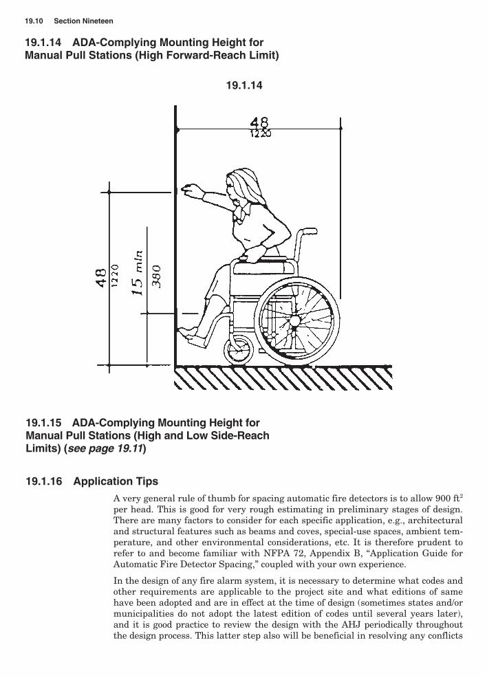
72 (1993), and BOCA19.1.14 ADA-Complying Mounting Height for Manual Pull Stations (High
Forward-Reach Limit)19.1.15 ADA-Complying Mounting Height for Manual Pull Stations (High and
Low Side-Reach Limits)19.1.16 Application Tips19.2.1 Fire Pump Applications19.2.2 Typical One-Line Diagram of Fire Pump System with Separate ATS19.2.3 Typical One-Line Diagram of Fire Pump System with ATS Integrated
with the Fire Pump Controller19.3.1 Wiring of Packaged Rooftop AHUs with Remote VFDs19.4.1 Wye-Delta Motor Starter Wiring19.5.1 Elevator Recall Systems19.5.2 Typical Elevator Recall/Emergency Shutdown Schematic19.5.3 Typical Elevator Hoistway/Machine Room Device Installation Detail19.6.0 Harmonic Effects and Mitigation
19.1.0 Fire Alarm Systems: Introduction
Fire alarm systems have become increasingly sophisticated and functionally morecapable and reliable in recent years. They are designed to fulfill two generalrequirements: protection of property and assets and protection of life. As a resultof state and local codes, the life-safety aspect of fire protection has become a majorfactor in the last two decades.
Section
19.1
19
CH19_Hickey 11/15/01 12:23 PM Page 19.1
There are a number of reasons for the substantial increases in the life-safety formof fire protection during recent years, foremost of which are
1. The proliferation of high-rise construction and the concern for life safety withinthese buildings.
2. A growing awareness of the life-safety hazard in residential, institutional, andeducational occupancies.
3. Increased hazards caused by new building materials and furnishings that createlarge amounts of toxic combustion products (i.e., plastics, synthetic fabrics, etc.).
4. Vast improvements in smoke detection and related technology made possiblethrough quantum advances in electronic technology.
5. The passing of the Americans with Disabilities Act (ADA), signed into law onJuly 26, 1990, providing comprehensive civil rights protection for individualswith disabilities. With an effective date of January 26, 1992, these require-ments included detailed accessability standards for both new construction andrenovation toward the goal of equal usability of buildings for everyone,regardless of limitations of sight, hearing, and mobility. This had a significantimpact on fire alarm system signaling devices, power requirements, anddevice locations.
19.1.1 Fire Alarm Systems: Common CodeRequirements
The following codes apply to fire alarm systems:
NFPA 70, National Electrical Code
NFPA 72, National Fire Alarm Code
NFPA 90A, Standard for the Installation of Air Conditioning and VentilationSystems
NFPA 101, Life Safety Code
BOCA, SBCCI, ICBO. The National Basic Building Code and National FirePrevention Code, published by the Building Officials Code AdministratorsInternational (BOCA), the Uniform Building and Uniform Fire Code of theInternational Conference of Building Officials (ICBO), and the StandardBuilding Code and the Standard Fire Prevention Code of the SouthernBuilding Code Congress International (SBCCI) all have reference to firealarm requirements.
Many states and municipalities have adopted these model building codes in full orin part. You should consult with the local authority having jurisdiction (AHJ) toverify the requirements in your area.
19.1.2 Fire Alarm System Classifications
NFPA 72 classifies fire alarm systems as follows:
� Household fire alarm system. A system of devices that produces an alarm signalin the household for the purpose of notifying the occupants of the presence of fireso that they will evacuate the premises.
� Protected-premises (local) fire alarm system. A protected-premises system thatsounds an alarm at the protected premises as the result of the manual operation ofa fire alarm box or the operation of protection equipment or systems, such as
19.2 Section Nineteen
CH19_Hickey 11/15/01 12:23 PM Page 19.2
Miscellaneous Special Applications 19.3
water flowing in a sprinkler system, the discharge of carbon dioxide, the detection of smoke, or the detection of heat.
� Auxiliary fire alarm system. A system connected to a municipal fire alarm systemfor transmitting an alarm of fire to the public fire service communications center.Fire alarms from an auxiliary fire alarm system are received at the public fireservice communications center on the same equipment and by the same methodsas alarms transmitted manually from municipal fire alarm boxes located onstreets. There are three subtypes of this system: local energy, parallel telephone,and shunt type.
� Remote supervising station fire alarm system. A system installed in accordancewith NFPA 72 to transmit alarm, supervisory, and trouble signals from one ormore protected premises to a remote location at which appropriate action is taken.
� Proprietary supervising station fire alarm system. An installation of fire alarmsystems that serves contiguous and noncontiguous properties, under one owner-ship, from a proprietary supervising station located at the protected property, atwhich trained, competent personnel are in constant attendance. This includesthe proprietary supervising station, power supplies, signal-initiating devices,initiating-device circuits, signal-notification appliances, equipment for theautomatic and permanent visual recording of signals, and equipment for initiatingthe operation of emergency building control services.
� Central station fire alarm system. A system or group of systems in which theoperations of circuits and devices are transmitted automatically to, recorded in,maintained by, and supervised from a listed central station having competentand experienced servers and operators who, on receipt of a signal, take suchaction as required by NFPA 72. Such service is to be controlled and operated bya person, firm, or corporation whose business is the furnishing, maintaining, ormonitoring of supervised fire alarm systems.
� Municipal fire alarm system. A system of alarm-initiating devices, receivingequipment, and connecting circuits (other than a public telephone network) usedto transmit alarms from street locations to the public fire service communicationscenter.
19.1.3 Fire Alarm Fundamentals: Basic Elements(Typical Local Protective Signaling System)(see page 19.4)
Regardless of type, application, complexity, or technology level, any fire alarmsystem is comprised of four basic elements:
1. Initiating devices
2. Control panel
3. Signaling devices
4. Power supply
These components must be electrically compatible and are interconnected by meansof suitable wiring circuits to form a complete functional system, as illustrated inFigure 19.1.3.
The figure shows a conventional version of a protected premises (local) fire alarmsystem, which is the most widely used classification type in commercial and insti-tutional buildings. The requirements for this type of system are detailed inChapter 3 of NFPA 72. Some highlights of this chapter’s requirements are worthyof note and are given in abridged form hereafter.
CH19_Hickey 11/15/01 12:23 PM Page 19.3
19.1.4 Fire Alarm System CircuitDesignations
Initiating-device, notification-appliance, and signaling-line circuits shall be desig-nated by class or style, or both, depending on the circuits’ capability to operateduring specified fault conditions.
19.1.5 Fire Alarm System: Class
Initiating-device, notification-appliance, and signaling-line circuits shall be per-mitted to be designated as either class A or class B depending on the capability ofthe circuit to transmit alarm and trouble signals during nonsimultaneous single-circuit-fault conditions as specified by the following:
1. Circuits capable of transmitting an alarm signal during a single open or a non-simultaneous single ground fault on a circuit conductor shall be designated asclass A.
2. Circuits not capable of transmitting an alarm beyond the location of the faultconditions specified in 1 above shall be designated as class B.
Faults on both class A and class B circuits shall result in a trouble condition on thesystem in accordance with the requirements of NFPA 72, Article 1-5.8.
19.1.6 Fire Alarm System: Style
Initiating-device, notification-appliance, and signaling-line circuits shall be permittedto be designated by style also, depending on the capability of the circuit to transmitalarm and trouble signals during specified simultaneous multiple-circuit-fault condi-tions in addition to the single-circuit-fault conditions considered in the designationof the circuits by class.
19.1.7 Performance of Initiating-DeviceCircuits (IDCs) (see page 19.5)
19.4 Section Nineteen
19.1.3
CH19_Hickey 11/15/01 12:24 PM Page 19.4
The assignment of class designations or style designations, or both, to initiatingcircuits shall be based on their performance capabilities under abnormal (fault)conditions in accordance with Table 19.1.7.
An initiating-device circuit shall be permitted to be designated as either style A, B,C, D, or E depending on its ability to meet the alarm and trouble performancerequirements shown during a single-open, single-ground, wire-to-wire short andloss of carrier fault condition.
19.1.8 Performance of Signaling-LineCircuits (SLCs) (see page 19.6)
The assignment of class designations or style designations, or both, to signaling-linecircuits shall be based on their performance capabilities under abnormal (fault)conditions in accordance with Table 19.1.8.
A signaling-line circuit shall be permitted to be designated as either style 0.5, 1, 2,3, 3.5, 4, 4.5, 5, 6, or 7 depending on its ability to meet the alarm and trouble per-formance requirements during a single-open, single-ground, wire-to-wire short,simultaneous wire-to-wire short and open, simultaneous wire-to-wire short andground, simultaneous open and ground, and loss of carrier fault conditions.
19.1.9 Notification-Appliance Circuits (NACs) (see page 19.6)
The assignment of class designations or style designations, or both, to notification-appliance circuits shall be based on their performance capabilities under abnormal(fault) conditions in accordance with Table 19.1.9.
A notification-appliance circuit shall be permitted to be designated as either styleW, X, Y, or Z depending on its ability to meet the alarm and trouble performancerequirements shown during a single-open, single-ground, and wire-to-wire shortfault condition.
19.1.10 Installation of Class A Circuits
All styles of class A circuits using physical conductors (e.g., metallic, optical fiber)shall be installed such that the outgoing and return conductors, exiting from andreturning to the control unit, respectively, are routed separately. The outgoing andreturn (redundant) circuit conductors shall not be run in the same cable assembly(i.e., multiconductor cable), enclosure or raceway.
Exception No. 1. For a distance not to exceed 10 ft (3 m) where the outgoing andreturn conductors enter or exit the initiating device, notification appliance, or control-unit enclosures; or
Exception No. 2. Where the vertically run conductors are contained in a 2-hourrated cable assembly or enclosed (installed) in a 2-hour rated enclosure other thana stairwell; or
Exception No. 3. Where permitted and where the vertically run conductors areenclosed (installed) in a 2-hour rated stairwell in a building fully sprinklered inaccordance with NFPA 13, “Standard for the Installation of Sprinkler Systems.”
Exception No. 4. Where looped conduit/raceway systems are provided, singleconduit/raceway drops to individual devices or appliances shall be permitted.
Exception No. 5. Where looped conduit/raceway systems are provided, singleconduit/raceway drops to multiple devices or appliances installed within a single roomnot exceeding 1000 ft2 (92.9 m2) in area shall be permitted.
19.1.11 Secondary Supply Capacity and Sources
From NFPA 72, Chapter 1, “Fundamentals,” the secondary source for a protectedpremises system should have a secondary supply source capacity of 24 hours and,at the end of that period, shall be capable of operating all alarm notification appli-ances used for evacuation or to direct aid to the location of an emergency for 5minutes. The secondary power supply for emergency voice/alarm communicationsservice shall be capable of operating the system under maximum load for 24hours and then shall be capable of operating the system during a fire or otheremergency condition for a period of 2 hours. Fifteen minutes of evacuation alarmoperation at maximum connected load shall be considered the equivalent of 2hours of emergency operation.
19.1.12 Audible Notification Appliances to Meet theRequirements of ADA, NFPA 72 (1993), and BOCA(see page 19.8)
19.1.13 Visual Notification Appliances to Meet theRequirements of ADA, NFPA 72 (1993), and BOCA(see page 19.9)
19.1.15 ADA-Complying Mounting Height forManual Pull Stations (High and Low Side-ReachLimits) (see page 19.11)
19.1.16 Application Tips
A very general rule of thumb for spacing automatic fire detectors is to allow 900 ft2
per head. This is good for very rough estimating in preliminary stages of design.There are many factors to consider for each specific application, e.g., architecturaland structural features such as beams and coves, special-use spaces, ambient tem-perature, and other environmental considerations, etc. It is therefore prudent torefer to and become familiar with NFPA 72, Appendix B, “Application Guide forAutomatic Fire Detector Spacing,” coupled with your own experience.
In the design of any fire alarm system, it is necessary to determine what codes andother requirements are applicable to the project site and what editions of samehave been adopted and are in effect at the time of design (sometimes states and/ormunicipalities do not adopt the latest edition of codes until several years later),and it is good practice to review the design with the AHJ periodically throughoutthe design process. This latter step also will be beneficial in resolving any conflicts
CH19_Hickey 11/15/01 12:24 PM Page 19.10
between codes and the ADAAG (these do occur) through equivalent facilitation, thusachieving compliance with all codes and regulations that apply.
It is also essential to coordinate with the architect, structural engineer, and othertrade disciplines (e.g., sprinkler systems) to determine their effects on fire alarmsystem requirements.
Fire alarm system technology today has reached a profoundly high level, withmultiplexed digital communication, 100 percent addressable systems, and even“smart” automatic fire detectors that can be programmed with profiles of theirambient environmental conditions, thus preventing nuisance alarms by beingable to discriminate between “normal” and “abnormal” conditions for their specificenvironment. These capabilities provide the designer with a lot of flexibility todesign safe and effective fire alarm systems.
19.2.1 Fire Pump Applications
The electrical requirements for electric-drive fire pumps are discussed in detail inChapters 6 and 7 and Appendix A of NFPA 20. These requirements are supple-mented by NFPA 70 (NEC), in particular, Articles 230, 430, and 700. The followingguideline items are design highlights (based on CT and MA requirements). Please
Miscellaneous Special Applications 19.11
19.1.15 ADA-Complying Mounting Height for Manual Pull Stations(High and Low Side-Reach Limits)
CH19_Hickey 11/15/01 12:24 PM Page 19.11
refer to any different or additional codes or requirements that may be applicable inyour state. However, the following generally should be applicable.
1. All electric fire pumps shall be provided with emergency power in accordancewith Article 700 of NFPA 70. State of Connecticut requirement (add toChapter 7, C.L.S.).
2. State of Massachusetts (add to 780 CMR, Item 924.3): Electrical fire pumps inmany occupancies require emergency power per NFPA 20 and NEC, Articles695 and 700.
3. State of Massachusetts (add to 527 CMR, NEC, Article 700): Emergency systemfeeders and generation and distribution equipment, including fire pumps, shallhave a 2-hour fire separation from all other spaces and equipment.
4. The fire pump feeder conductors shall be physically routed outside the buildingor enclosed in 2 in of concrete (1-hour equivalent fire resistance) except in theelectrical switchgear or fire pump rooms (NFPA 20, 6-3.1.1).
5. All pump room wiring shall be in rigid, intermediate, or liquid-tight flexiblemetal conduit (NFPA 20, 6-3.1.2; MI cable is added to this in the 1993 version).
6. Maximum permissible voltage drop at the fire pump input terminals is 15 per-cent (NFPA 20, 6-3.1.4).
7. Protective devices (fuses or circuit breakers) ahead of the fire pump shall notopen at the sum of the locked-rotor currents of the facility or the fire pumpauxiliaries (NFPA 20, 6-3.4).
8. The pump room feeder minimum size shall be 125 percent of the sum of the firepump(s), jockey pump, and pump auxiliary full-load currents (NFPA 20, 6-3.5).
9. Automatic load shed and sequencing of fire pumps is permitted (NFPA 20, 6-7).
10. Remote annunciation of the fire pump controller is permitted per NFPA 20, 7-4.6and 7-4.7. Note: A good practice is to assume that this will happen and makeprovisions for it, i.e., fire alarm connections or wiring to the appropriate location.
11. When necessary, automatic transfer switch may be used. It must be listed for firepump use. It may be a separate unit or integrated with the fire pump controllerin a barriered compartment (NFPA 20, 7-8.2).
12. A jockey pump is not required to be on emergency power.
13. Step loading the fire pump onto an emergency generator can help control thegenerator size. A time-delay relay (0 to 60 seconds) to start or restart a fire pumpwhen on generator power will help coordinate generator loading. The relayshould be a part of the fire pump controller. (See Item 9 above.)
14. Reduced-voltage starters (i.e., autotransformer or wye-delta) for fire pumpsare recommended.
15. Fire pumps, fire pump controllers, and fire pump listed automatic transferswitches generally are provided under division 15. Division 16 is responsiblefor powering, wiring, and connecting this equipment.
19.12 Section Nineteen
CH19_Hickey 11/15/01 12:24 PM Page 19.12
Miscellaneous Special Applications 19.13
19.2.2
19.2.2 Typical One-Line Diagram of Fire PumpSystem with Separate ATS
CH19_Hickey 11/15/01 12:24 PM Page 19.13
19.2.3 Typical One-Line Diagram of FirePump System with ATS Integrated with theFire Pump Controller
19.14 Section Nineteen
19.2.3
CH19_Hickey 11/15/01 12:24 PM Page 19.14
19.3.1 Wiring of Packaged Rooftop AHUs withRemote VFDs
Miscellaneous Special Applications 19.15
19.3.1
An emerging trend in HVAC design is the use of packaged rooftop air-handlingunits (AHUs) with remote mounted variable-frequency drives (VFDs). In this cir-cumstance, multiple electrical connections and significant additional wiring arerequired, not the traditional single point of connection needed previously. It istherefore critically important to coordinate closely with the mechanical design pro-fessionals to ensure that complete and proper wiring is provided.
19.4.1 Wye-Delta Motor Starter Wiring
A common misapplication that is encountered is the improper sizing of the sixmotor leads between the still very popular wye-delta reduced-voltage motor starterand the motor. This is best demonstrated by an example.
Assume that you have a 500-ton electrical centrifugal chiller operating at 460 V,three-phase, 60 Hz, with a nameplate rating of 588 full-load amps (FLA). You
CH19_Hickey 11/15/01 12:24 PM Page 19.15
normally would apply the correct factor of 125 percent required by NEC Article 440to arrive at the required conductor ampacity: 588 � 1.25 � 735 ampacity for eachof the three conductors. Since there will be six conductors between the load side ofthe starter and the compressor motor terminals, the 735 ampacity is divided by 2,and you would select six conductors, each having an ampacity of not less than 368A. Referring to NEC Article 310, Table 310.16 for insulated copper conductors at75°C would result in the selection of 500-kcmil conductors.
This wire size is incorrect when used between the wye-delta starter and motorterminals.
The problem is caused by a common failure to recognize that the motor may consistof a series of single-phase windings. To permit the transition from wye-start todelta-run configuration, the motor is wound without internal connections. Each endof the three internal motor windings is brought out to a terminal, as shown inFigure 19.4.1(A).
19.16 Section Nineteen
19.4.1A Wye-to-delta internal motor windings brought out to terminals.
19.4.1B Wye-start, delta-run motor winding configuration.
The motor windings are configured as required for either starting or running atthe starter, as shown in Figure 19.4.1(B).
In the running-delta configuration, the field wiring from the load side of thestarter to the compressor motor terminals consists of six conductors, electricallybalancing the phases to each of the internal motor windings, as described inFigure 19.4.1(C).
Note, for example, that motor winding T1 � T4 is connected to the line voltageacross phase L1 � L2.
It should be apparent that the windings within the motor are single-phase connectedto the load side of the starter. Thus the interconnecting field wiring between thestarter and motor must be sized as though the motor were single-phase. Electrical
CH19_Hickey 11/15/01 12:24 PM Page 19.16
terminology simply describes this motor as being phase connected, and the currentcarried by the interconnecting conductors as phase amps.
To size the conductors between the motor starter and the motor correctly, therefore,it is necessary to calculate the ampacity with the 125 percent feeder sizing factorrequired by the NEC on a single-phase basis as follows:
Ampacity per terminal conductor �
For the example given,
Ampacity per terminal conductor � � 424
Thus it is clear that the current in the conductors between the starter and the motoron a single-phase basis is 58 percent of the three-phase value, not 50 percent, asoriginally assumed, because the current in one phase of a three-phase system in thedelta-connected winding is 1 divided by �3� due to the vector relationship.
In the original example, the conductors were sized for a minimum ampacity of 368 A.From the NEC, 500-kcmil copper conductors at 75°C have a maximum allowableampacity of 380 A. The preceding calculation discloses that the conductors should beselected for not less than 424 A. Referring to the NEC again, 600-kcmil conductorshave a maximum allowable ampacity of 420 A. In many cases, depending on theinterpretation of the local electrical inspector, 600-kcmil would be acceptable (usuallywithin 3 percent is acceptable). However, 500-kcmil wire would not be.
Almost needless to say, the conductors supplying the line side of the wye-deltastarter are sized as conventional three-phase motor conductors.
19.5.1 Elevator Recall Systems
Elevator recall systems are discussed here rather than under fire alarm systems inSection 19.1 because they can be installed as a stand-alone system, even thoughthey are generally a part of a fire alarm system. Also, several codes are applicableto the installation of these systems, specifically ANSI/ASME A17.1, Safety Codefor Elevators and Escalators, NFPA 72, National Fire Alarm Code, NFPA 13,Standard for Installation of Sprinklers, and NFPA 101, Life Safety Code—to whichthe reader is referred for complete details.
Further, applying these codes properly in combination can be problematic (e.g.,whether sprinklers are present or not), coupled with the requirements of theauthority having jurisdiction (which generally are more stringent).
588 � 1.25��
1.73
3-phase FLA � 1.25���
1.73
Miscellaneous Special Applications 19.17
19.4.1C Field wiring between starter and motor in wye-start, delta-run configuration.
CH19_Hickey 11/15/01 12:24 PM Page 19.17
Briefly stated, ANSI/ASME A17.1 is written so as to ensure that an elevator carwill not stop and open the door on a fire-involved floor by requiring elevators to berecalled nonstop to a designated safe floor when smoke detectors located in eleva-tor lobbies, other than the designated level, are actuated. When the smoke detectorat the designated level is activated, the cars return to an alternate level approvedby the enforcing authority.
If the elevator is equipped with front and rear doors, it is necessary to have smokedetectors in both lobbies at the designated level.
Activation of a smoke detector in any elevator machine room, except a machine roomat the designated level, shall cause all elevators having any equipment located inthat machine room and any associated elevators of a group automatic operation toreturn nonstop to the designated level. When a smoke detector in an elevatormachine room is activated that is at the designated level, with the other conditionsbeing the same as above, the elevators shall return nonstop to the alternate level orthe appointed level when approved by the authority having jurisdiction.
NFPA 72 requires that in facilities without a building fire alarm system, thesesmoke detectors shall be connected to a dedicated fire alarm system control unitthat shall be designated as “elevator recall control and supervisory panel.” Thusthe stand-alone operation first noted above.
As noted, the foregoing is by no means complete but captures the intent and basiccause-and-effect relationship between an elevator recall system’s smoke detectorsand elevator operation under the various stated conditions.
Figure 19.5.2 shows a typical elevator recall/emergency shutdown schematic.Please note that the authority having jurisdiction required that the elevator recallsmoke detectors in this application be independent of the building fire alarm sys-tem smoke detectors. Figure 19.5.3 shows a typical elevator hoistway/machine roomdevice installation detail for the same project application shown in Figure 19.5.2.Note that the fire alarm system is fully addressable and that the elevator machinerooms are at the designated level for egress.
19.5.2 Typical Elevator Recall/EmergencyShutdown Schematic (see page 19.19)
19.5.3 Typical Elevator Hoistway/Machine RoomDevice Installation Detail (see page 19.20)
19.6.0 Harmonic Effects and Mitigation
Harmonics are the result of nonlinear loads so prevalent with late-twentieth-centurytechnology. Personal computers, adjustable-speed drives, uninterruptable powersupplies, to name a few, all have nonlinear load characteristics. What all nonlin-ear loads have in common is that they convert ac to dc and contain some kind ofrectifier.
A sinusoidal system can supply nonsinusoidal current demands because any nonsi-nusoidal waveform can be generated by the proper combination of harmonics of thefundamental frequency. Each harmonic in the combination has a specific ampli-tude and phase relative to the fundamental. The particular harmonics drawn by anonlinear load are a function of the rectifier circuit and are not affected by the typeof load.
19.18 Section Nineteen
CH19_Hickey 11/15/01 12:24 PM Page 19.18
Harmonic Origins. Harmonics have two basic origins: current-wave distortion andvoltage-wave distortion.
� Harmonics do no work but contribute to the rms current the system must carry.� Triplen harmonics are additive in the system neutral.� These currents return to the transformer source over the neutral and are dissi-
pated as heat in the transformer, cables, and load devices.
Symptoms of Harmonic Problems
� Overheated neutral conductors, panels, and transformers� Premature failure of transformers, generators, and UPS systems� Lost computer data� Interference on communications lines� Operation of protective devices without overload or short circuit� Random component failure in electronic devices� Operating problems with electronic devices not traceable to component problems� Interaction between multiple VFDs throwing off setpoints� Interaction between UPSs and their supplying generators� System power factor reduction and related system capacity loss� Problems with capacitor operation and life
Harmonic Mitigation. Currently, there are no devices that completely eliminateharmonics and thus their effects; however, they can be mitigated substantially tocontrol their deleterious consequences. Essentially, current techniques consist ofaccommodating harmonics and include the following:
� Increasing neutral sizes, usually doubling feeder neutral sizes and installing aseparate neutral with each single-phase branch circuit of a three-phase system,effectively a triple-neutral, rather than a single common neutral of the same sizeas the phase conductor
� k-Rated transformers� Harmonic-rated distribution equipment such as switchgear and panelboards� Passive filters such as phase shifters, phase cancelers, zig-zag transformers, and
Most of the preceding involve “beefing up” to accommodate harmonics.
Active versus Passive Devices
Active devices:
Pros Cons
Works well for mitigation of Expensive.harmonics upstream of the device.
Protects the transformer. High maintenance costs.
Uses power.
Works only upstream.
Miscellaneous Special Applications 19.21
CH19_Hickey 11/15/01 12:24 PM Page 19.21
Passive devices:
Pros Cons
No electronic circuitry. Work only upstream toaccommodate harmonics.
Very reliable. Location is critical.
Phase loads must be balanced.
Can be overloaded.
Dissipate heat.
Require fused disconnect.
Ultimate/Ideal Solution. The ultimate ideal solution would
� Eliminate the production of harmonics at the source (not just accommodatethem).
� Be passive and therefore cost-effective, reliable, and efficient.� Be easily installed and not require protection.� Handle any load on the distribution system (not require load balancing to be
effective).� Resist overloading (not become a harmonic sink for the rest of the distribution