72
CIVIL AIR PATROL U.S. Air Force Auxiliary Mission Aircrew Task Guides Mission Observer Revision December 2014
CIVIL AIR PATROL U.S. Air Force Auxiliary
Mission Aircrew Task Guides
Mission Observer
Revision December 2014

Task # Title MO O-2002 Operate the Aircraft Radios
MO O-2010 Use In-flight Services
MO O-2011 Operate the VOR and DME
MO O-2012 Operate the GPS
MO O-2013 Plot a Route on a Sectional Chart
MO O-2107 Prepare for a Trip to a Remote Mission Base
MO O-2108 Assist in ELT Searches
MO O-2109 Assist in Planning and Performing a Route Search
MO O-2110 Assist in Planning and Performing a Parallel Search
MO O-2112 Assist in Planning and Performing Point Based Searches
MO O-2115 Assist in Planning and Performing a Creeping Line Search
MO P-2007 Discuss Mission Observer Duties and Responsibilities
MO P-2008 Discuss the Dangers of Icing
MO P-2009 Discuss the Dangers of Reduced Visibility Conditions
MO P-2010 Discuss the Dangers of Wind and Thunderstorms
MO P-2011 Discuss the Effects of Density Altitude on Aircraft Performance
MO P-2012 Identify Controlled and Special Use Airspaces on a Sectional
1 Dec14
MO O-2002 OPERATE THE AIRCRAFT RADIOS
CONDITIONS
You are a Mission Observer trainee and must demonstrate how to operate the aircraft communications radios, the CAP VHF FM radio, and an Audio Panel.
OBJECTIVES
Demonstrate and discuss the use of the aircraft communications radios, CAP VHF FM radio and Audio Panel.
TRAINING AND EVALUATION
Training Outline 1. As a Mission Observer trainee, knowing how to set up and use the aircraft radios is essential. This enables
the observer to assist the pilot during times of heavy workloads, and to communicate effectively with mission base and ground units.
The aircraft radio is the primary means of communication in aviation. To effectively use the radio, mission pilots and observers must be knowledgeable not only of how to communicate, but when communication is required during CAP missions. Observers may operate the aircraft communications radios in order to reduce pilot workload, and they use the FM radio to communicate with ground units. Some aviation frequencies are designed for air-to-air communications and may be used by CAP aircraft (or any other general aviation aircraft). 123.1 MHz is the official SAR frequency. 122.75 & 122.85 MHz are air-to-air communications frequencies (and for use by private airports not open to the general public). 122.90 MHz is the Multicom frequency; it can be used for search and rescue, but is also used for other activities of a temporary, seasonal or emergency nature (note, however, that it is also used by airports without a tower, FSS or UNICOM). Follow your communications plan, if applicable, and don't abuse these frequencies. Look at the sectional to see if 122.90 MHz is used by nearby airports, and always listen before you transmit.
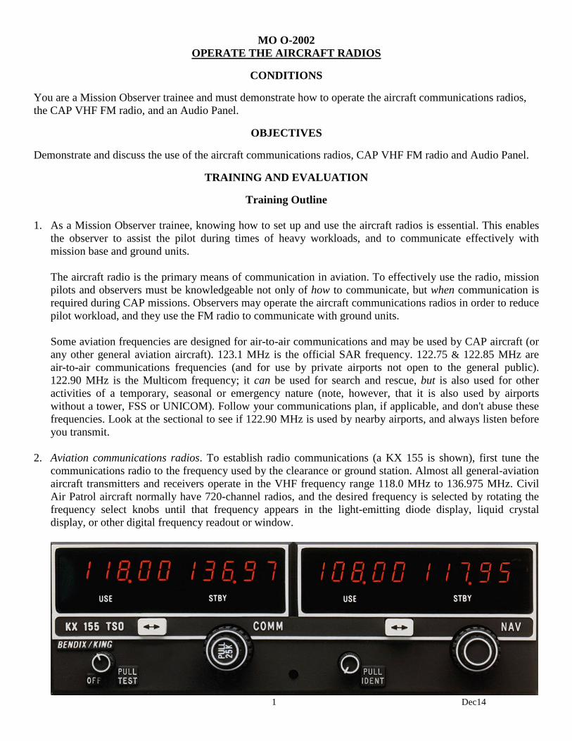
2. Aviation communications radios. To establish radio communications (a KX 155 is shown), first tune the
communications radio to the frequency used by the clearance or ground station. Almost all general-aviation aircraft transmitters and receivers operate in the VHF frequency range 118.0 MHz to 136.975 MHz. Civil Air Patrol aircraft normally have 720-channel radios, and the desired frequency is selected by rotating the frequency select knobs until that frequency appears in the light-emitting diode display, liquid crystal display, or other digital frequency readout or window.
2 Dec14
The 720-channel radios are normally tuned in increments of 50 kilocycles (e.g., 119.75 or 120.00). They can be tuned in increments of 25 kilocycles (e.g., 119.775) pulling out on the tuning knob, but the last digit of the frequency will not be shown in the display (e.g., 119.775 will be displayed as 119.77). [Sometimes, for brevity, air traffic controllers assign such frequencies as "one-one nine point seven seven," meaning 119.775, not 119.770. The operator cannot physically tune the radio to 119.770, and this may be confusing.] Before transmitting, first listen to the selected frequency. An untimely transmission can "step on" another transmission from either another airplane or ground facility, so that all the transmissions are garbled. Many pilots have been violated for not complying with instructions that, it was later determined, had been blocked or "stepped on" by another transmission. Next, mentally prepare your message so that the transmission flows naturally without unnecessary pauses and breaks (remember "Who, Where, What"). You may even find it helpful to jot down what you want to say before beginning the transmission. When you first begin using the radio, you may find abbreviated notes to be a convenient means of collecting thoughts with the proper terminology. As your experience level grows, you may find it no longer necessary to prepare using written notes. Stuck mike Occasionally, the transmit button on aircraft radio microphones gets stuck in the transmit position, resulting in a condition commonly referred to as a “stuck mike.” This allows comments and conversation to be unintentionally broadcast. Worse yet, it also has the effect of blocking all other transmissions on that frequency, effectively making the frequency useless for communication by anyone within range of the offending radio. You may suspect a stuck mike when, for no apparent reason, you do not receive replies to your transmissions, especially when more than one frequency has been involved. You may notice that the 'T' (transmit symbol) is constantly displayed on your communications radio and, in the case of the PMA7000MS audio panel, the transmit (TX) light in the lower right-hand corner is on continuously. You may notice a different sound quality to the background silence of the intercom versus the noise heard when the microphone is keyed but no one is talking. Often the problem can be corrected by momentarily re-keying the microphone. If receiver operation is restored, a sticking microphone button is quite likely the problem.
3. Call signs. CAP aircraft have been authorized to use FAA call signs, just like the major airlines and
commuter air carriers. This helps differentiate us from civil aircraft, air taxis, and many other commercial aircraft. Our FAA authorized callsign is "CAP XX XX," where the numbers are those assigned to each Wing's aircraft. The numbers are stated in 'group' form. For example, the C172 assigned to Amarillo, Texas is numbered 4239, where 42 is the prefix identifying it as a Texas Wing aircraft. The call sign is thus pronounced "CAP Forty-Two Thirty-Nine." It is important to use the group form of pronunciation because FAA air traffic controllers expect it of us. [NOTE: There are a few exceptions to this rule, such as when you perform certain counter-drug operations. In these rare cases you may be directed to use the aircraft 'N' number as your call sign.]
The initial transmission to a station starts with the name of the station you’re calling (e.g., Amarillo Ground), followed by your aircraft call sign. You almost always identify yourself using your aircraft's CAP flight designation. Once you’ve identified the facility and yourself, state your position (e.g., "at the ramp") and then make your request. [NOTE: CAP aircraft should use the word "Rescue" in their call sign when priority handling is critical. From the example above, this would be "Rescue CAP Forty-Two Thirty-Nine." DO NOT abuse the use of this code; it should only be used when you are on a critical mission and you need priority handling. NEVER use the word "rescue" during training, exercises or drills.]
3 Dec14
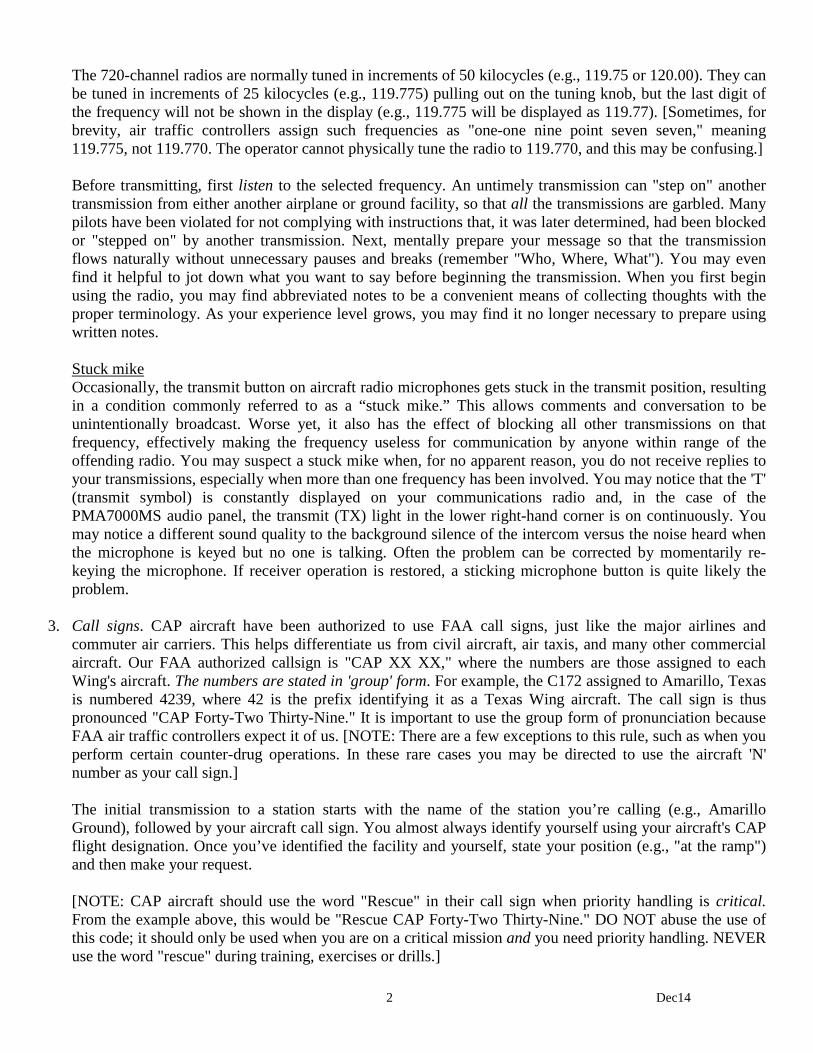
4. CAP VHF FM radio. CAP has authorization to use special frequencies in order to communicate with government agencies and to our own ground forces. For this purpose CAP aircraft have a VHF FM radio that is separate from the aviation comm radios. This radio is dedicated to air-to-ground communications, and is normally operated by the observer or scanner. Several of the frequencies programmed into the radio are frequencies assigned to CAP by the U.S. Air Force, and are used to communicate with CAP bases and ground teams (do not publish or reveal these frequencies to unauthorized personnel). Others are programmed at the direction of the Wing Communications Officer (e.g., mutual aid, fire, police, park service, forest service, and department of public service); these frequencies almost always require prior permission from the controlling agency before use. [CAP is replacing the older Yaesu and NAT NPX radios with the TDFM-136 (below), which will be discussed here.]
The TDFM-136 is a P25-compliant airborne transceiver capable of operating in the 136 MHz to 174 MHz range (digital or analog) in 2.5 KHz increments. It can have up to 200 operator-accessible memory positions, each capable of storing a receive frequency, a transmit frequency, a separate tone for each receive and transmit frequency, an alphanumeric identifier for each channel, and coded squelch information for each channel. Data can be entered via the 12-button keypad but is normally downloaded from a PC. Operating frequencies, alphanumeric identifiers and other related data are presented on a 96-character, four-line LED matrix display. It is capable of feedback encryption. The FM Radio is selected using Com 3 on the Audio Panel; it is also directly accessed using the Push-to-Talk toggle switch located in an armrest by the rear seat of the aircraft. National will enter the first four main frequencies (Primary, Secondary, Ground Tactical and Air-to-Ground) and the wing communications officers will enter the rest. Therefore, all you will just have to know is how to use the radio. The radio also has a scan function that can scan any or all of the main channels stored in the preset scan lists; scan lists, if enabled, are set by the wing communications officer. As shown in the figure, the radio simultaneously displays two frequencies. The upper line is the Main (MN) frequency and the lower is the Guard (GD) frequency. Normally, you will be set up to transmit and receive on the Main and be able to receive the Guard frequency. This feature allows mission base to contact you at any time (via Guard), no matter what frequency you are using (Main).

4 Dec14
Controls and normal settings: a. The knob above the MN/GD switch is the power switch and controls volume for Main. The knob above
the G1/G2 switch is the volume control for Guard. b. The "Squelch" pushbutton is not used (automatic squelch). Don't push it. c. The MN/GD toggle switch selects the frequency on which you will transmit and receive. It is normally
set to MN. d. The G1/G2 toggle switch selects the Guard frequency you are monitoring. It is normally set to G1. e. The HI/LO toggle switch selects transmitter power (10 watts or 1 watt). It is normally set to HI.
Keypad operation: a. Pressing and holding "4" (Scroll Memory Down) will let you scroll down through the programmed
memories (it wraps around). Upon reaching the desired entry, release the button. "6" (Scroll Memory Up) lets you scroll up. [Note: scroll speed increases the longer you hold the buttons.]
b. Pressing "5" (Scan) lets you select a scan list to scan, and to start or stop the scan. Once the scan list you want is displayed press # ENTER to start the scan or press * ESC to stop the scan. [Note: this function must be enabled by the wing communications officer for it to work.}
c. Pressing and holding "2" (Display - Brighter) will increase display brightness; "8" (Display - Dimmer) decreases brightness.
When you get in the aircraft and power up the radio it should be set to MN, G1 and HI. Use pushbutton 4 or 6 to select the assigned Main frequency. As another example, let’s say you are working with the U.S. Forest Service and have their frequency on Main. Mission base, noting that you have not called in your "Operations Normal" report, calls you using the G1 frequency. You will hear mission base over Guard (its set to G1), regardless of what is coming over the Main frequency. You simply take the MN/GD switch to GD and answer "Ops Normal," and then return the switch to MN and carry on with the mission.
5. Required FM radio reports. As a minimum, the aircrew must report the following to mission base:
a. Radio check (initial flight of the day) b. Take off time c. Time entering a search area d. Time exiting a search area e. Landing time f. Operations normal ("Ops Normal"), at intervals briefed by mission staff (usually every 30 minutes)
6. Audio Panel. An audio panel serves as the "hub" for the aircraft's communication and navaid equipment.
Whatever type of audio panel is installed in the aircraft, it serves two basic functions:
a. Selecting the 'active' radio (COM 1, COM 2, etc.). This is the radio over which you will transmit when you use the push-to-talk switch or the hand mike.
b. Allows communication and navigational instruments to be directed to the aircraft's overhead speaker or
to the headphones. 7. The position of the switch and the pushbuttons on the audio panel should be checked as part of each
preflight. There is no set rules on how they should be set, and settings may vary according to the mission and the airspace you will be flying in. The important thing is to realize how the panel is set up so that your equipment will function as you need and expect them to function.

5 Dec14
8. KMA 24. One of the most common older audio panels, the KMA 24 is still found in many CAP aircraft. The switch on the right-hand portion of the panel determines which radio you will transmit on; also, if none of the pushbuttons are depressed, the switch setting (e.g., COM 1) determines which radio you are listening to. The pushbuttons are arranged in two rows: the upper row is associated with the aircraft's overhead speaker, and depressing these pushbuttons will direct their associated equipment to the speaker (e.g., press the ADF pushbutton and the ADF will be heard on the speaker); the bottom row is associated with the headphones and serves the same function.
Depressing a pushbutton routes the signal from the associated instrument (e.g., a com radio or the ADF) to the speaker or your headphones, regardless of the setting on the COM switch. This comes in handy when you want to monitor two frequencies at the same time. For example, you have Center on the #1 radio and the COM switch in the COM 1 position. You will be flying near a local airport and want to listen to its CTAF. Set the CTAF in the #2 radio and depress the COM 2 PHONE pushbutton. You will now be able to hear both frequencies, but still will only be able to transmit on Center frequency. The CAP FM radio is usually routed through the TEL pushbuttons, and the DF unit is often routed through the ADF pushbuttons. The two most common mistakes made with this type of audio panel include: transmitting on the wrong frequency because you set the desired frequency in one radio but failed to select the corresponding COM channel; and failing to hear a message over the FM radio because you failed to depress the appropriate pushbutton (usually the TEL pushbutton) to direct the call to the overhead speaker or headphones.
9. PMA7000MS. The PMA7000MS is CAP's newest audio panel, and is installed in conjunction with the new
FM radio (TDFM-136). This audio panel was custom-designed to meet CAP SAR operational requirements. In addition to normal audio panel functions, this unit contains an automatic voice-activated (VOX) stereo intercom system with automatic squelch control.
6 Dec14
Unit power is turned on and off by pushing the Volume knob. In the Off (or Fail-Safe) position the pilot is connected directly to Com 1 to allow communication capability regardless of unit condition (any time power is removed or turned off the audio selector will be placed in the fail-safe mode). The power switch also controls the audio selector panel functions, intercom, and marker beacon receiver. Unless the Mic Selector is in Com 3 mode, at least one of the selected audio LEDs will be on (Com 1 or Com 2).
The Volume control knob adjusts the loudness of the intercom for the pilot and observer only; it has no effect on selected radio levels or crewmembers' volume level. Adjust the radios and intercom volume for a comfortable listening level for the pilot. [Most general aviation headsets today have built-in volume controls; therefore, crewmember volume can be adjusted on the headset. For best performance your headset microphone must be placed within ¼ inch of your lips, preferably against them. It is also a good idea to keep the microphone out of a direct wind path.] Mic Selector switch and receiver switches. Receiver audio is selected through two momentary and six latched, push-button, backlit switches. Because the rotary Mic (microphone) Selector switch controls what transceiver is being heard, the Com l and Com 2 push-buttons are of the momentary type and do not remain in when selected. Because of this, you will always hear the audio from the transceiver that is selected for transmit by the rotary Mic Selector switch (in other words, you can't transmit without listening to the receiver). You can identify which receivers are selected by noting which of the switch LEDs are illuminated. Push buttons labeled Nav 1, Nav 2, COM 3, DME, MKR (Marker), ADF and SPR (Speaker) are "latched" type switches. When one of these buttons is pressed, it will stay in the "in" position; press the switch again and it will be in the "out" position and remove that receiver from the audio. When selected, the SPR button will place all selected audio on the aircraft's overhead speaker (Note: the speaker amplifier is not active in the split mode).
When the Mic Selector switch is in the Com 1 position, both pilot and observer will be connected to the Com l transceiver. Only the person that presses their Push-to-Talk (PTT) will be heard over the aircraft radio. Turning the rotary switch to the Com 2 position will place pilot and observer on the Com 2 transceiver. The PMA7000MS gives priority to the pilot’s PTT; if the observer it transmitting and the pilot presses her PTT, the pilot’s microphone will be heard over the selected transmitter. In Com 3, both pilot and copilot are using the CAP FM radio.
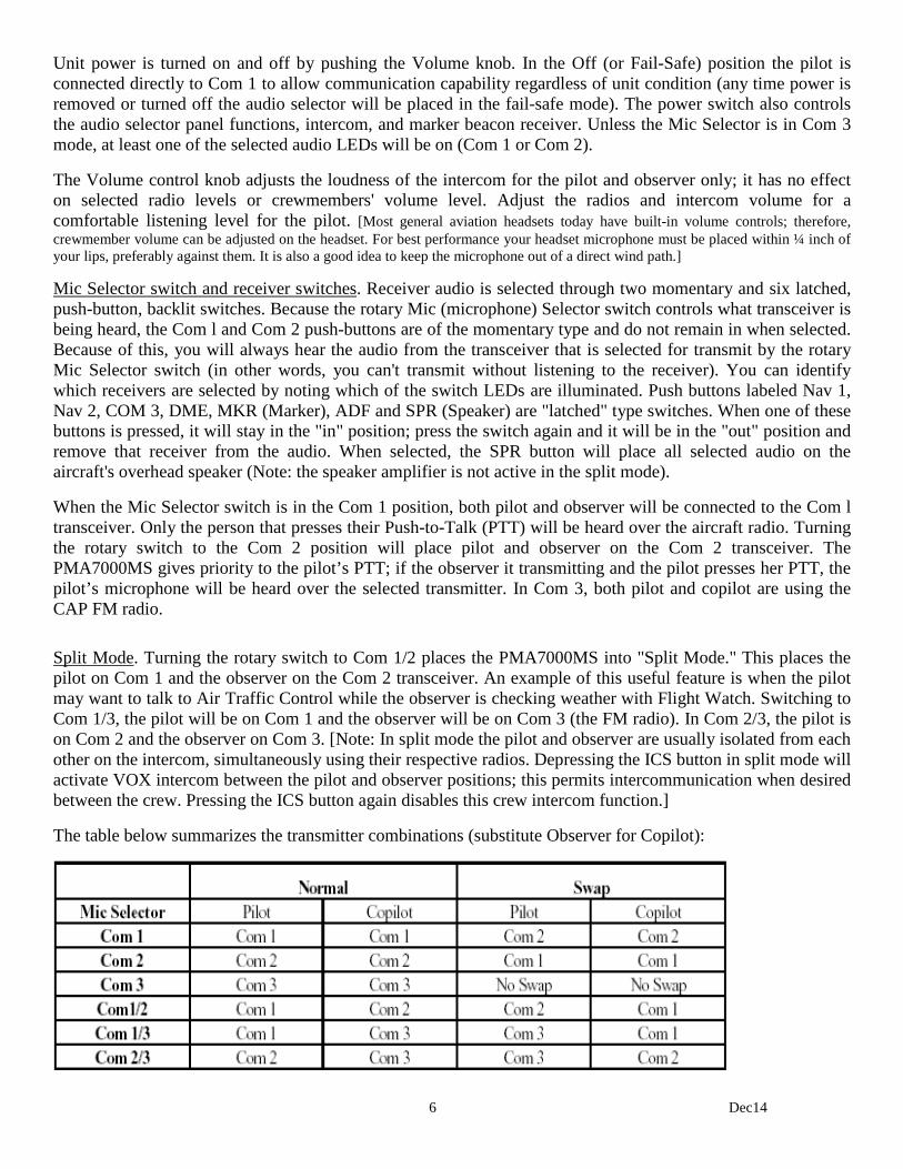
Split Mode. Turning the rotary switch to Com 1/2 places the PMA7000MS into "Split Mode." This places the pilot on Com 1 and the observer on the Com 2 transceiver. An example of this useful feature is when the pilot may want to talk to Air Traffic Control while the observer is checking weather with Flight Watch. Switching to Com 1/3, the pilot will be on Com 1 and the observer will be on Com 3 (the FM radio). In Com 2/3, the pilot is on Com 2 and the observer on Com 3. [Note: In split mode the pilot and observer are usually isolated from each other on the intercom, simultaneously using their respective radios. Depressing the ICS button in split mode will activate VOX intercom between the pilot and observer positions; this permits intercommunication when desired between the crew. Pressing the ICS button again disables this crew intercom function.]
The table below summarizes the transmitter combinations (substitute Observer for Copilot):
7 Dec14
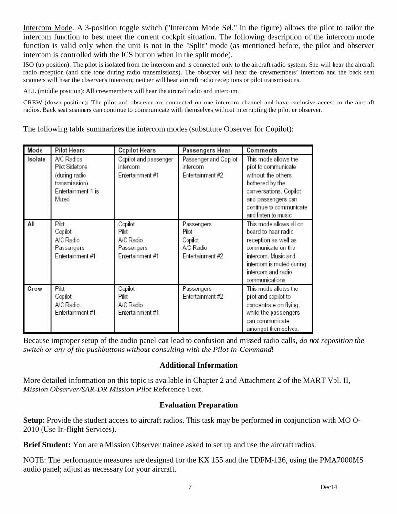
Intercom Mode. A 3-position toggle switch ("Intercom Mode Sel." in the figure) allows the pilot to tailor the intercom function to best meet the current cockpit situation. The following description of the intercom mode function is valid only when the unit is not in the "Split" mode (as mentioned before, the pilot and observer intercom is controlled with the ICS button when in the split mode). ISO (up position): The pilot is isolated from the intercom and is connected only to the aircraft radio system. She will hear the aircraft radio reception (and side tone during radio transmissions). The observer will hear the crewmembers’ intercom and the back seat scanners will hear the observer's intercom; neither will hear aircraft radio receptions or pilot transmissions.
ALL (middle position): All crewmembers will hear the aircraft radio and intercom.
CREW (down position): The pilot and observer are connected on one intercom channel and have exclusive access to the aircraft radios. Back seat scanners can continue to communicate with themselves without interrupting the pilot or observer. The following table summarizes the intercom modes (substitute Observer for Copilot):
Because improper setup of the audio panel can lead to confusion and missed radio calls, do not reposition the switch or any of the pushbuttons without consulting with the Pilot-in-Command!
Additional Information
More detailed information on this topic is available in Chapter 2 and Attachment 2 of the MART Vol. II, Mission Observer/SAR-DR Mission Pilot Reference Text.
Evaluation Preparation
Setup: Provide the student access to aircraft radios. This task may be performed in conjunction with MO O-2010 (Use In-flight Services).
Brief Student: You are a Mission Observer trainee asked to set up and use the aircraft radios.
NOTE: The performance measures are designed for the KX 155 and the TDFM-136, using the PMA7000MS audio panel; adjust as necessary for your aircraft.
8 Dec14
Evaluation
Performance measures Results
1. Set up and use the aircraft communications radio:
a. Power, volume and squelch controls. P F
b. 50 and 25 kilocycle frequency adjustments. P F
c. Set in primary and standby frequencies, and switch between them (flip-flop). P F
d. Discuss proper use of CAP call signs, including when to use "rescue". P F
e. Discuss stuck mike indications and strategies. P F
2. Set up and use the CAP VHF FM radio:
a. Power, volume and squelch controls. P F
b. Select assigned frequencies (main and guard channels). P F
c. Keypad controls (scroll and scan). P F
d. Give required mission FM radio reports (may be simulated). P F
3. Set up and use the audio panel:
a. Power and volume controls. P F
b. Microphone selector switch and receiver switches (describe all positions). P F
c. Split mode (describe all transmitter combinations). P F
d. Intercom modes (describe all modes). P F
Student must receive a pass on all performance measures to qualify in this task. If the individual fails any measure, show what was done wrong and how to do it correctly.
1 Dec14
MO O-2010 USE IN-FLIGHT SERVICES
CONDITIONS
You are a Mission Observer trainee and must discuss and use in-flight services.
OBJECTIVES
Discuss and use in-flight services.
TRAINING AND EVALUATION
Training Outline 1. As a Mission Observer trainee, knowing how to obtain in-flight services is very helpful. Observers may use
in-flight services in order to reduce pilot workload, and being able to get this information may be very useful during emergencies.
2. Flight Service Stations (FSS). Provide assistance for preflight and in-flight briefings, scheduled and
unscheduled weather broadcasts, and weather advisories. Selected FSS provide transcribed weather briefings. Enroute weather information can be obtained from the Enroute Flight Advisory Service ("Flight Watch") by tuning 122.0 MHz into the radio and calling “Flight Watch.” It mainly provides actual weather and thunderstorms along your route. Additionally, Flight Watch is the focal point for rapid receipt and dissemination of pilot reports (PIREP'S). Other flight service frequencies are indicated on the sectional charts.
3. Scheduled Weather Broadcasts. All flight service stations having voice facilities on radio ranges (VOR) or
radio beacons (NDB) broadcast weather reports and Notice to Airmen information at 15 minutes past each hour from reporting points within approximately 150 miles of the broadcast station.
4. Automatic Terminal Information Service (ATIS). At many airports, the FAA dedicates one or more
transmitters and frequencies to continuous taped broadcasts of weather observations, special instructions, and NOTAMS that relate to the airport or nearby navigational facilities. Broadcast weather information is about actual observations for the smaller, terminal area, not forecasts. ATIS information is updated hourly, but may be updated sooner if the weather, special instructions or NOTAMs change significantly. Usually, you must listen to ATIS recordings on the communication radio (the frequency for the ATIS transmission is found on the sectional chart near the airport’s name, or in a table on the reverse side of the sectional title panel). A typical ATIS transmission may sound like this: "Atlanta Hartsfield Airport, arrival information 'November'. 2350 Zulu weather -- measured ceiling 800 overcast, 1 1/2 miles in fog and haze. Temperature 61 degrees, dew point 60 degrees, wind calm, altimeter 29.80. ILS approaches in progress to Runways 8 Left and 9 Right. Landing runways 8 Left and 9 Right. Atlanta VOR out of service. Taxiway Mike closed between taxiways Delta and Sierra. Read back all ‘hold short' instructions. Advise controller on initial contact you have information 'November'."
5. Hazardous In-Flight Weather Advisory Service (HIWAS). You can also receive advisories of hazardous
weather on many VORs. As the HIWAS name implies, this information relates only to hazardous weather such as tornadoes, thunderstorms, or high winds. Navaids having HIWAS broadcast capability are annotated on the sectional chart. When receiving a hazardous weather report, ATC or FSS facilities initiate the taped HIWAS transmissions, and ATC then directs all aircraft to monitor HIWAS.
2 Dec14
6. Automated Weather Observation System (AWOS). At many airports, the FAA has installed Automated Weather Observation Systems. Each system consists of sensors, a computer-generated voice capability, and a transmitter. Information provided by AWOS varies depending upon the complexity of the sensors installed. Airports having AWOS are indicated on sectional charts by the letters AWOS adjacent to the airport name.
7. Automated Surface Observation System (ASOS). The primary surface weather observing system in the U.S.,
the FAA has installed hundreds of ASOS. Each system consists of sensors, a computer-generated voice capability, and a transmitter. Information provided by ASOS varies depending upon the complexity of the sensors installed. ASOS can be heard by telephone, and so is very useful in flight planning. Information includes: wind speed, direction and gusts; visibility and cloud height; temperature and dew point; altimeter setting and density altitude.
8. Pilot Weather Report (PIREP). FAA stations are required to solicit and collect PIREPs whenever ceilings
are at or below 5,000 feet above the terrain, visibility is at or less than 5 miles, or thunderstorms, icing, wind shear, or turbulence is either reported or forecast. These are extremely useful reports, and all pilots are encouraged to volunteer reports of cloud tops, upper cloud layers, thunderstorms, ice, turbulence, strong winds, and other significant flight condition information. PIREP's are normally given to Flight Watch. They are then included at the beginning of scheduled weather broadcasts by FAA stations within 150 nautical miles of the area affected by potentially hazardous weather. Pilots are advised of these reports during preflight briefings by FAA and national weather service stations, and by air/ground contacts with FAA stations. PIREP's can help you avoid bad weather and warn you to be ready for potential hazards.
Additional Information
More detailed information on this topic is available in Chapter 2 and Attachment 2 of the MART Vol. II, Mission Observer/SAR-DR Mission Pilot Reference Text.
Evaluation Preparation
Setup: Provide the student access to a telephone and an aircraft radio. This task may be performed in conjunction with MO O-2002 (Demonstrate Operation of the Aircraft Radios).
Brief Student: You are an Observer trainee asked to use in-flight services.
Evaluation
Performance measures Results
1. Demonstrate and discuss how to use the following in-flight services:
a. Flight Service Stations and scheduled weather broadcasts. P F
b. Obtain an ATIS report. P F
c. HIWAS. P F
d. Obtain an AWOS and/or ASOS report. P F
e. Give a PIREP report (may be simulated). P F
Student must receive a pass on all performance measures to qualify in this task. If the individual fails any measure, show what was done wrong and how to do it correctly.

1 Dec14
MO O-2011 OPERATE THE VOR AND DME
CONDITIONS
You are an Observer trainee and must use the VOR and DME for navigation and position determination.
OBJECTIVES
Demonstrate how to use the VOR and DME for navigation and position determination.
TRAINING AND EVALUATION
Training Outline 1. As a Mission Observer trainee, knowing how to use navaids and their limitations is essential for situational
awareness. The Very High Frequency Omnidirectional Range (VOR) radio navigation system and Distance Measuring Equipment (DME) allows the aircraft to be flown to a desired location, such as a search pattern entry point, with precision and economy. Once in the search or assessment area, these navaids allow the pilot to fly the assigned area fairly accurately. From the mission staff's viewpoint, proper use of these navaids assures them that the assigned area was actually flown -- the only variables left to accommodate are search effectiveness and the inherent limitations of scanning.
One drawback is that setting up and manipulating the VORs and DME may distract the pilot (and observer) from looking outside of the aircraft. The great majority of CAP missions are performed in VFR conditions, and the CAP aircrew must not forget the importance of looking where you're going. The best way to avoid this trap is to become and continue to be very familiar with the operation of the GPS. Training and practice (along with checklists or aids) allows each crewmember to set or adjust instruments with minimum fuss and bother, thus allowing them to return their gaze outside the aircraft where it belongs. All members of the aircrew should be continuously aware of this trap. Additionally, it is important that observers use this equipment to help the pilot maintain situational awareness. The observer should always know the aircraft's position on the sectional chart and the VOR/DME enables him or her to do so with good accuracy.
2. ADF. The Automatic Direction Finder is used to receive radio guidance from stations such as four-course
ranges, radio beacons, and commercial broadcast facilities. The automatic direction finder indicates the direction of the station being received shown in relation to the heading of the aircraft: thus, the ADF can be helpful in maintaining situational awareness. The ADF is the least accurate of all the navigational instruments.

2 Dec14
3. VOR. The VOR radio navigation system transmits 360 directional radio beams or radials that, if visible,
would resemble the spokes radiating from the hub of a bicycle wheel. Each station is aligned to magnetic north so that the 000 radial points from the station to magnetic north. Every other radial is identified by the magnetic direction to which it points from the station, allowing the pilot to navigate directly to or from the station by tracking along the proper radial. The VOR is an accurate and reliable navigational system, and is the current basis for all instrument flight in the U.S. To help light plane pilots plan and chose routings, the FAA has developed the Victor airway system, a “highway” system in the sky that uses specific courses to and from selected VORs. When tracing the route of a missing aircraft, search airplanes may initially fly the same route as the missing plane, so it is very important you know the proper procedures for tracking VOR radials.
The figure above shows a VOR indicator and the components that give the information needed to navigate, including a vertical pointer, OFF/TO-FROM flag or window, and a course-select knob. The vertical pointer, also called a course deviation indicator (CDI), is a vertically mounted needle that swings left or right showing the airplane's location in relation to the course selected beneath the course pointer. The OFF/TO-FROM indicator shows whether the course selected will take the airplane to or from the station. When it shows “OFF”, the receiver is either not turned on or it’s not receiving signals on the selected frequency. The course selector knob is used to select the desired course to fly either toward or away from the station. Flying to the VOR station is simple. Find the station’s frequency and its Morse code audio identifier using the sectional chart. Next, tune the receiver to the correct frequency and identify the station by listening to its Morse code (if you can’t positively identify the station, you should not use it for navigation). After identifying the station, slowly turn the course selector knob until the TO-FROM indicator shows TO and the CDI needle is centered. If you look at the course that's selected beneath the course pointer at the top of the indicator, you’ll see the course that will take you directly to the station. The pilot turns the aircraft to match the airplane's heading with that course and corrects for any known winds by adding or subtracting a drift correction factor. The pilot keeps the CDI centered by using very small heading corrections and flies the aircraft directly to the station; when the aircraft passes over the station, the TO-FROM indicator will flip from TO to FROM. To fly away from a station, first tune and identify the VOR and then slowly rotate the course select knob until the CDI is centered with a FROM indication in the window. Look at the selected course, again normally at the top of the indicator, to determine the outbound course. The pilot turns the aircraft to that heading, corrects for wind drift, and keeps the CDI needle in the center to fly directly away from the station.

3 Dec14
VORs can be used to determine a position in relation to a selected station. Rotate the course select knob slowly until the CDI is centered with a FROM indication, and look beneath the reciprocal course pointer for the radial. You can draw that radial as a line of position from the station's symbol on the sectional chart. Each VOR station on the chart has a surrounding compass ring already oriented towards magnetic north. Therefore, it isn’t necessary to correct for magnetic variation. The use of the printed compass circle surrounding the station on the chart eliminates the need for using the plotter's protractor as well. Use any straight edge to draw the radial by connecting the station symbol with a pencil line through the appropriate radial along the circle. The radial drawn on the chart shows direction, but does not indicate distance from the station. But, you can get an accurate position “fix” by repeating the procedure with another VOR. [Note: In order to use a VOR for instrument flight, the receiver must be functionally checked every thirty days (or prior to any instrument flight). This check must be performed by an instrument rated pilot and logged in the aircraft's flight logbook.]
4. DME. Finding bearing or direction to a station solves only one piece of the navigation puzzle: knowing the
distance to the station is the final piece to the puzzle that allows fliers to navigate more precisely. You can use crossing position lines from two radio stations to obtain your distance from the stations, but an easier method is provided by Distance Measuring Equipment. DME continuously measures the distance of the aircraft from a DME ground unit that is usually co-located with the VOR transmitter (then called a VORTAC). The system consists of a ground-based receiver/transmitter combination called a transponder, and an airborne component called an interrogator. The interrogator emits a pulse or signal, which is received by the ground-based transponder. The transponder then transmits a reply signal to the interrogator. The aircraft's DME equipment measures the elapsed time between the transmission of the interrogator's signal and the reception of the transponder's reply and converts that time measurement into a distance. This measurement is the actual, straight-line distance from the ground unit to the aircraft, and is called slant range. This distance is continuously displayed, typically in miles and tenths of miles, on a dial or digital indicator on the instrument panel. When DME is used in combination with VOR, you can tell at a glance the direction and distance to a tuned station.
Slant range
Ground Range
DME measures straight-line distance, or slant range, so there is always an altitude component within the displayed distance. If you fly toward a station at an altitude of 6,000 feet over the station elevation, the DME will never read zero. It will continuously decrease until it stops at one mile. That mile represents the aircraft’s altitude above the station. The distance readout will then begin to increase on the other side of the station. Under most circumstances the altitude component of slant range can be ignored, but when reporting position using DME, especially to air traffic controllers, it is customary to report distances in "DME", not nautical miles, e.g., "Holly Springs 099° radial at 76 DME." [Some DME equipment can also compute and display the actual ground speed of the aircraft, provided that the aircraft is flying directly to or from the ground station. In all other circumstances, the ground speed information is not accurate and should be ignored.]

4 Dec14
Additional Information
More detailed information on this topic and examples are available in Chapter 5 of the MART Vol. II, Mission Observer/SAR-DR Mission Pilot Reference Text.
Evaluation Preparation
Setup: Provide the student access to an aircraft or simulator. This task may be performed in conjunction with MO O-2012 (Operate the GPS).
Brief Student: You are an Observer trainee asked to determine aircraft position with the VOR and DME.
Evaluation
Performance measures Results
1. Use (or discuss) the ADF to determine approximate position. P F
2. Determine aircraft position with the VOR, and discuss how to use the VOR to fly to/from a station. Also determine position by cross-radials. P F
3. Determine aircraft position with the DME, and discuss the limitations of DME. P F
4. Discuss the limitations of each navaid. P F
Student must receive a pass on all performance measures to qualify in this task. If the individual fails any measure, show what was done wrong and how to do it correctly.
1 Dec14
MO O-2012 OPERATE THE GLOBAL POSITIONING SYSTEM
CONDITIONS
You are an Observer trainee and must use the GPS for navigation and position determination.
OBJECTIVES
Demonstrate how to use the GPS for navigation and position determination.
TRAINING AND EVALUATION
Training Outline 1. As a Mission Observer trainee, knowing how to use the GPS and its limitations is essential. The Global
Positioning System (GPS) allows the aircraft to be flown to a desired location, such as a search pattern entry point, with precision and economy. Once in the search or assessment area, the GPS allows the pilot to fly the assigned area precisely and thoroughly. From the mission staff's viewpoint, proper use of the GPS assures them that the assigned area was actually flown -- the only variables left to accommodate are search effectiveness and the inherent limitations of scanning.
One drawback is that setting up and manipulating the GPS may distract the pilot (and observer) from looking outside of the aircraft. The great majority of CAP missions are performed in VFR conditions, and the CAP aircrew must not forget the importance of looking where you're going. The best way to avoid this trap is to become and continue to be very familiar with the operation of the GPS. Training and practice (along with checklists or aids) allows each crewmember to set or adjust instruments with minimum fuss and bother, thus allowing them to return their gaze outside the aircraft where it belongs. All members of the aircrew should be continuously aware of this trap. Additionally, it is important that observers use this equipment to help the pilot maintain situational awareness. The observer should always know the aircraft's position on the sectional chart, and the GPS enables him or her to do so with great accuracy.
2. The Global Positioning System relies on a chain of 24 satellite transmitters in polar orbits about the earth.
The speed and direction of each satellite, as well as each satellite's altitude is precisely maintained so that each satellite remains in a highly accurate and predictable path over the earth's surface at all times. The GPS receiver in the aircraft processes signals transmitted by these satellites and triangulates the receiver's position, which the user again can read directly in latitude and longitude coordinates from a digital display. The system is substantially more accurate than LORAN, VOR, DME, or ADF and has several advantages.
Because the transmitters are satellite (not ground) based, and the signals are essentially transmitted downward, system accuracy is not significantly degraded in mountainous terrain. Additionally, the system is not normally vulnerable to interference from weather or electrical storms. Receivers can typically process as many as twelve received signals simultaneously, and can automatically deselect any satellite whose signal doesn't meet specific reception parameters. The system can function with reasonable accuracy using as few as three received signals.
3. To a new operator, the GPS is complex and can initially increase the user's workload. Pilots and observers
must read the operating manual or instructions and become thoroughly familiar with GPS operation before flight, so that operating the GPS will not become a distraction from more important tasks. Also, many

2 Dec14
manufacturers have CD simulators (e.g., U.S. Aviation Technologies' Apollo GX55; www.upsat.com) that allow individuals to practice use of the GPS on a computer.
4. CAP is standardizing the fleet with the Apollo GX-50/55 (below). Even if your aircraft has a different GPS,
the basic functions are primarily the same. The Garmin G1000® and GNS 430w are covered in separate training programs.
All GPS units display bearing and distance to waypoints (i.e., airports, VORs, intersections, and user waypoints); position can also be determined by displaying current lat/long coordinates. For emergency use, all GPS units have a feature that allows you quickly and easily display bearing and distance to the nearest airports or VORs (often a list of the ten nearest facilities). The GPS displays altitude, ground speed, estimated time to the waypoint, and ground track. GPS databases also contain extensive information about selected waypoints (e.g., an airport) such as runway length and alignment, lighting, approaches, frequencies, and even FBO details such as the availability of 100LL fuel and hours of operation. The GPS receiver also allows pilots to: Fly directly to any position The ability to fly directly to any position (e.g., an airport, navaid, intersection, or user waypoint) saves time and fuel. This reduces transit time, thus allowing more of the crew’s allowed duty day to be spent in the search area. Any of these positions can be entered as the destination through a simple procedure. Additionally, all GPS have a "Nearest Airport" and "Nearest VOR" function, where you can easily display a list of the nearest airports or VORs and then select it as your destination. Positions can also be grouped into flight plans. Once the destination is entered into the GPS, the heading and the ground track can be monitored. By matching the heading and ground track (or keeping the CDI centered), you are automatically compensating for wind and thus flying the shortest possible route to your destination. Fly between any two points The ability to fly directly between any two points greatly improves search effectiveness. These points, usually defined by latitude and longitude (lat/long), can be flown in either of two ways: a. The points can be entered into the GPS as user-defined waypoints. The waypoints can then be recalled in
the same manner as you would display an airport or navaid, or they can be entered into a flight plan. b. The pilot can fly between the points by observing the current lat/long display (i.e., a real-time readout of
latitude and longitude).

3 Dec14
5. Two factors have reduced search effectiveness in the past: drifting off course due to shifts in wind direction, and drifting off course because of the lack of adequate boundaries (e.g., cross-radials or visible landmarks). Now any search pattern can be flown precisely without relying on cross-radials or ground references. The crew and the mission staff know that a route or area has been covered thoroughly. Also, GPS allows the crew to remain within assigned boundaries, which greatly improves safety when more than one aircraft is in the search area at the same time.
NOTE: The Apollo GX-50/55 has a "moving map," which greatly enhances situational awareness. It shows aeronautical and ground features in (scalable) detail, and also displays special use airspace. Another feature, added to the unit for CAP use, is the SAR MAP mode. This feature allows you to select, define and fly directly to a CAP grid, and to superimpose a search pattern on the grid (e.g., parallel, creeping line or expanding square). The SAR features will be covered in another task guide.
Additional Information
More detailed information on this topic and examples are available in Chapter 5 and Attachment 2 of the MART Vol. II, Mission Observer/SAR-DR Mission Pilot Reference Text.
Evaluation Preparation
Setup: Provide the student access to an aircraft or a GPS simulator. This task may be performed in conjunction with MO O-2011 (Operate the VOR and DME).
Brief Student: You are an Observer trainee asked to determine aircraft position with the GPS.
4 Dec14
Evaluation
Performance measures Results
1. Using the operator's manual, discuss the operation of the GPS. P F
2. Using the operator's manual, display information provided by the GPS: P F
a. Altitude.
b. Ground speed.
c. Heading to waypoint and current heading.
d. Track over ground (ground track).
e. Estimated time to the waypoint (ETE).
3. Use the operator's manual to determine current position using: P F
a. Bearing and distance to waypoints.
b. Present position (lat/long coordinates).
c. Moving map display (if applicable).
4. Use the operator's manual to enter a destination waypoint: P F
a. Airport.
b. VOR.
c. User-defined (lat/long coordinates).
5. Using the operator's manual, display "nearest airport" and "nearest VOR." P F
Student must receive a pass on all performance measures to qualify in this task. If the individual fails any measure, show what was done wrong and how to do it correctly.

1 Dec14
MO O-2013 PLOT A ROUTE ON A SECTIONAL CHART
CONDITIONS
You are an Observer trainee and must plot a simple route on a sectional chart.
OBJECTIVES
Plot a course on a sectional chart, select checkpoints along a route, and calculate how long it will take to fly the route.
TRAINING AND EVALUATION
Training Outline 1. As a Mission Observer trainee, knowing how to plot a route on a sectional chart is essential in order to assist
the pilot, and help maintain situational awareness.
2. Plot the course. To determine a heading, locate the departure and destination points on the chart and lay the
edge of a special protractor, or plotter, along a line connecting the two points. Use a marker to trace the route. Read the true course for this leg by sliding the plotter left or right until the center point, or grommet, sits on top of a line of longitude. When the course is more to the north or south, you can measure it by centering the grommet on a parallel of latitude, then reading the course from the inner scale that’s closer to the grommet.
3. Distance. To determine the distance you're going to travel, lay the plotter on the route and read the distance
using the scale that's printed on the plotter's straight edge: one edge measures nautical miles and the other statute miles.
4. Flight time. To determine the time it will take to fly between any two points, divide the distance (in nm) by
the proposed airspeed (in knots).
2 Dec14
5. Checkpoints. There are a number of ways you can add information to your chart that will help during the flight. Tick marks along the course line at specific intervals will help you keep track of your position during flight (situational awareness). Some individuals prefer five- or ten-nautical mile (nm) intervals for tick marks, while others prefer two- or four-nm intervals. Four-nautical mile spacing works well for aircraft that operate at approximately 120 knots. Since the 120-knot airplane travels 2 nm every minute, each 4 nm tick mark represents approximately two minutes of flight time. On the left side of the course line you have more tick marks, at five-nm intervals, but measured backward from the destination. In flight, these continuously indicate distance remaining to the destination, and you can easily translate that into the time left to your destination.
The next step in preparing the chart is to identify checkpoints along the course; you can use these to check your position on- or off-course, and the timing along the leg. Prominent features that will be easily seen from the air make the best checkpoints, and many like to circle them or highlight them with a marker in advance. You should select easy (large) targets such as tall towers, cities and towns, major roads and railroads, and significant topological features such as lakes and rivers. Try not to select checkpoints that are too close together. During a mission, checkpoint spacing will be controlled by the search altitude and weather conditions and visibility at the time of the flight.
Additional Information
More detailed information on this topic is available in Chapter 5 of the MART Vol. II, Mission Observer/SAR-DR Mission Pilot Reference Text.
Evaluation Preparation
Setup: Provide the student with a sectional chart and a plotter. Give the student two points on the chart.
Brief Student: You are an Observer trainee asked to plot a course, select checkpoints along the route, and calculate time in flight.
Evaluation
Performance measures Results
Given a sectional chart, a plotter, and two points on the chart (e.g., two airports): P F
1. Plot a course between the two points.
2. Select checkpoints along the route. Discuss the reason you selected the checkpoints.
3. Calculate the time it will take an aircraft (120 knots with no wind) to fly the route.
Student must receive a pass on all performance measures to qualify in this task. If the individual fails any measure, show what was done wrong and how to do it correctly.
1 Dec14
MO O-2107 PREPARE FOR A TRIP TO A REMOTE MISSION BASE
CONDITIONS
You are a Mission Observer trainee and must help to prepare for a trip to a remote mission base.
OBJECTIVES
Prepare for a trip to a remote mission base, acting as mission commander. Assist in performing pre-trip planning and inspections, preflight tasks and briefings, filling out a CAP flight plan, and after-landing tasks.
TRAINING AND EVALUATION
Training Outline As a Mission Observer trainee, the ability to help the Pilot in Command (PIC) to prepare for a trip to a remote mission base is essential. The urgency of events, coupled with a hasty call-out, may leave you and other crewmembers feeling rushed as you prepare to leave for a mission. This is where a good pre-mission checklist comes in handy. As a minimum, check the crew (and yourself) for the following: [Note: Several of these items are the sole responsibility of the Pilot in Command; they are presented here to familiarize you with what to expect from the PIC.]
1. Use the Mission Checklist in Attachment 2 (CAP Flight Guide) or similar checklist (e.g., the In-Flight
Guide and Aircrew Aid) as necessary. 2. Before you leave. The urgency of events, coupled with a hasty call-out, may leave you and other
crewmembers feeling rushed as you prepare to leave for a mission. This is where a good mission checklist comes in handy. As a minimum, check the crew (and yourself) for the following: A. Check proper uniforms (CAPM 39-1) and credentials of aircrew
1) CAP Membership 2) CAP Driver’s License (on CAPF 101), if applicable 3) CAPF 101/SQTR (note experience and tasks to be accomplished) 4) Aircrew safety currency (eServices); Pilot currency (including a Photo ID) 5) For passengers, PIC review CAPR 60-1 section 2-3 (Passenger Requirements)
B. Check personal equipment
1) Clothing sufficient and suitable for the entire trip 2) Personal supplies (civilian clothing, headset, charts, maps, plotter, log, checklists, fluids and snacks) 3) Personal survival equipment (in addition to the aircraft kit) suitable for the entire trip 4) Sufficient money for the trip 5) Cell phone (including spare battery and charger) and ECD/EFB
C. Check aircraft equipment
1) Current Aeronautical Charts for the entire trip and gridded charts for the mission area 2) Maps for the mission area (e.g., road atlas, county maps, topo maps), plus clipboard and markers 3) Towbar, tie-downs, chocks, Pitot tube cover and engine plugs, fuel tester, sick sacks, cleaning gear 4) Check special equipment (e.g., computer, camera, portable GPS, spare batteries) 5) Survival kit (fits trip and mission area terrain), headsets, flashlight, binoculars and multi-tool
2 Dec14
D. FAA Weather Briefing and CAP Flight Release 1) PIC will perform a Weight & Balance (reflecting weights for the crew, special equipment and
baggage) a) Include fuel assumptions (fuel burn, winds, power setting, distance, and 1-hour reserve) b) Ensure fuel reserve (plan to land with one hour's fuel, computed at normal cruise)
2) Assist the PIC in completing the ORM worksheet in WMIRS (verify within CAPR 60-1 flight visibility and wind limitations). PIC will upload the W&B into WMIRS
3) Assist the PIC in completing the Planning and Briefing sections of your inbound sortie in WMIRS including discrepancy check
4) Verify aircrew within duty period/crew rest limitations of CAPR 60-1 5) PIC will obtain FAA briefing [Simulate; ask for FDC and Local NOTAMs and SUA status and file
FAA Flight Plan] a) Enter 'CAP XXXX' in the Aircraft Identification section b) Put the 'CAP' and 'N' numbers in the Remarks section (e.g., CAP4239 is N239TX)
6) PIC will brief the crew on her fuel management plan (assumptions, refueling stops and reserve), FDC and Local NOTAMs, and Special Use Airspaces
7) Assist the PIC in obtaining a CAP Briefing and Flight Release [Simulate the release] E. Preflight
1) Verify load is per the Weight & Balance (baggage, survival kit, extra equipment and luggage) 2) Double-check navigational databases (include EFB/ECD), aeronautical charts, and maps 3) Ensure required aids onboard (Flight Guide, distress and air-to-ground signals, fuel tester, tools) 4) Windshield and windows clean, and towbar, chocks, tie-downs, Pitot tube covers and engine plugs
stowed 5) Check and test special equipment (cameras, airborne repeater, SDIS, GIIEP), including spare
batteries 6) Parking area clear of obstacles (arrange for a wing-walker if one will be needed to clear obstacles) 7) PIC will perform passenger briefing and review emergency egress procedure 8) Review taxi plan/diagram and brief crew assignments for taxi, takeoff and departure 9) Remind crew that most midair collisions occur in or near the traffic pattern 10) Enter settings into GPS (e.g., destination or flight plan, entry points and waypoints) 11) Organize the cockpit
NOTE: One of the most overlooked assets you have in the aircraft is the glove box. This area is ideal for items such as small, laminated sheets for the crew and passenger briefing, crosswind chart, public relations cards (like those from the CD program), FM radio frequencies and call signs, ELT deactivation stickers, and a GPS cheat-sheet. Other items could include a small cleaning rag (like for glasses) to clean the GPS display and a backup flashlight. Check the glove box periodically and purge unnecessary stuff
Additional Information
More detailed information and figures on this topic are available in Chapter 10 and Attachment 2 of the MART Vol. II, Mission Observer/SAR-DR Mission Pilot Reference Text.
Practice
Setup: Give the student an assignment to go to a remote mission base. The base should be located on a large (unfamiliar) airport in controlled airspace -- Class B, if practical. The student should have access to mission materials, the Flight Guide, and WMIRS.
The student will assist the PIC in planning a simulated a trip to a remote mission base. All tasks that can be performed will not be simulated.
3 Dec14
The evaluator should play the role of the PIC, particularly for performing inspections and giving briefings and instructions to the observer trainee. The observer will be given preflight and pilot briefings.
For this simulated sortie, watch for:
1) Thorough knowledge of documents and equipment required for an extended stay at a remote base.
2) Assists PIC with accurate and thorough planning for the trip.
3) Assists pilot in completion of sortie Planning, Briefing and Debriefing information in WMIRS.
4) Understanding of safety and mission briefings.
Evaluation Preparation
Setup: Give the student an assignment to go to a remote mission base. The base should be located on a large (unfamiliar) airport in controlled airspace -- Class B or C, if practical. The student should have access to mission materials, the Flight Guide, and a CAPF 104.
The student will assist in planning a simulated a trip to a remote mission base. All tasks that can be performed will not be simulated.
The evaluator should play the role of the PIC, particularly for performing inspections and giving briefings and instructions to the observer trainee. The observer will be given preflight and pilot briefings.
Brief Student: You are a Mission Observer trainee asked to help prepare for a trip to a remote mission base.
4 Dec14
Evaluation
Performance measures Results
1. Check for proper uniform, credentials and equipment. P F
2. State the duty period and crew rest limitations per CAPR 60-1. P F
3. Assist in checking the aircraft:
a. Check for required equipment on board (e.g., tie downs, survival kit, cleaning gear). P F
b. Clean windows, as necessary. P F
4. Assist in completing Planning and Briefing sections in WMIRS. P F
5. Receive a briefing from the mission pilot:
a. Fuel assumptions and fuel stop. P F
b. Airspace restrictions, NOTAMS, and destination airport diagrams. P F
c. ORM and W&B P F
Student must receive a pass on all performance measures to qualify in this task. If the individual fails any measure, show what was done wrong and how to do it correctly.

1 Dec14
MO O-2108 ASSIST IN ELT SEARCHES
CONDITIONS
You are a Mission Observer trainee and must assist in performing ELT searches.
OBJECTIVES
Assist the mission pilot in locating an Emergency Locator Transmitter (practice beacon) using the homing and wing null ELT search methods. Discuss the aural and metered search methods, and reflection and interference.
NOTE: These methods apply to the L-Tronics DF unit; operation of the Doppler DF (Becker & RhoTheta) is covered in the “Electronic Search Patterns” section of the CAP Mission Pilot slides.
TRAINING AND EVALUATION
Training Outline 1. As a Mission Observer trainee, knowing how to assist the mission pilot in locating an Emergency Locator
Transmitter (ELT) is essential. There are several methods that can be used, the most common of which are the homing and wing null methods. You should also be familiar the aural and metered search method, and how reflections and signal interference can affect the search.
2. Homing is an electronic search method that uses the Direction Finder (DF) to track the ELT signal to its
source. Tune the direction finder (DF) to the ELT operating frequency; the pilot will fly the aircraft to the transmitter by keeping the left/right needle centered. ELT’s may transmit on either 121.5 MHz VHF, 243.0 MHz UHF, or both frequencies simultaneously. These emergency frequencies are usually the ones monitored during a search, but homing procedures can be used on any radio frequency to which both a transmitter and DF receiver can be tuned.
First you have to determine the direction to the ELT. When you fly directly toward a signal, the left/right DF needle remains centered. However, when you head directly away from the signal, the needle also centers. A simple, quick maneuver is used to determine if you are going toward or away from the signal. Starting with the left/right needle centered, the pilot turns the aircraft in either direction so that the needle moves away from center. If he turns left, and the needle deflects to the right, the ELT is in front. If the pilot turns back to the right to center the needle, and then maintains the needle in the center, you will eventually fly to the ELT. If, in the verification turn, the pilot turns left and the needle swings to the extreme left, then the ELT is behind you. Continue the left turn until the needle returns to the center. You are now heading toward the ELT, and as long as the pilot maintains the needle in the center, you will fly to the ELT. Flying toward the ELT, maintaining the needle in the center of the indicator is the actual homing process. If the needle starts to drift left of center, steer slightly left to bring the needle back to the center. If it starts to
2 Dec14
drift right, turn slightly back to the right. Once you have completed the direction-verification turn, you will not need large steering corrections to keep the needle in the center. When passing over the ELT or transmission source, the left/right needle will indicate a strong crossover pattern. The needle will make a distinct left-to-right or right-to-left movement and then return to the center. This crossover movement is not a mere fluctuation; the needle swings fully, from one side of the indicator to the other and then returns to the center. During homing you may encounter situations where the needle suddenly drifts to one side then returns to center. If the heading has been steady, and the needle previously centered, such a fluctuation may have been caused by a signal from a second transmitter. Another aircraft nearby can also cause momentary needle fluctuations that you might not hear, but the needle in the DF will react to it. Signal reflections from objects or high terrain can also cause needle fluctuations at low altitudes in mountainous terrain or near metropolitan areas.
3. Wing shadow. The wing shadow (or signal null) method is based on the assumption that the metal skin of
the search aircraft’s wing and fuselage will block incoming ELT signals from the receiving antenna during steep-banked turns.
Due to the length of the description of this search method and the number of figures, refer to the "Wing Shadow method (wing null)" section of Chapter 7 for details.
4. The aural (or hearing) search technique is based on an assumption that an ELT's area of apparent equal
signal strength is circular.
Please refer to the "Aural (or hearing) search" section of Chapter 7 for details. 5. To employ the metered search method, the observer uses a signal strength meter to monitor the ELT signal.
Once the aircraft enters the search area, the observer plots two positions of equal meter strength.
Please refer to the "Metered search" section of Chapter 7 for details. 6. Signal reflection and interference. Radio signals reflect off terrain and manmade objects, and this can be a
problem for search and rescue teams. In an electronic search, it is vitally important to know if the equipment is reacting to reflected signals and what you can do to overcome the problem.
Please refer to the "Signal Reflection and Interference" section of Chapter 7 for details.
7. Night ELT searches. Darkness eliminates your ability to precisely determine your position in reference to
the ground, and that impacts the effectiveness of your search. Once you’ve successfully homed to an ELT you can usually narrow the target area down to about one square mile. Unless the ELT is located on an airfield or the occupants of the target aircraft are able to signal you, you will have to call in a ground team or land at the nearest airport, arrange for transportation, and find the ELT with hand-held equipment.
If you have a GPS that will plot your flown track, you can pinpoint the ELT position more accurately. After station passage is assured, fly another two minutes. Make a 90° turn (either way) and fly for another five minutes. From this point, DF back to the ELT and repeat the process, making turns in the same direction. When you look at the plotted track on the GPS, the lines will cross at a point over the ELT. You can then read off a lat/long position from the GPS, which is usually good to better than 1/2 mile - certainly good enough to get a ground crew headed to the right place. This technique can also be used in IMC.

3 Dec14
8. IMC ELT searches. It is possible to DF in IMC, but this is dangerous and not to be undertaken lightly. Instrument flight imposes a higher workload on the pilot and demands a higher level of training and proficiency. As discussed earlier, the ability to fly steep-banked turns and other maneuvers without losing altitude is demanding for even the most proficient pilot. Trying to conduct these maneuvers while flying solely by referencing the flight instruments is not wise; the pilot can easily get vertigo and lose control of the aircraft. For these reasons only highly trained and proficient pilots should attempt to DF in IMC, and it is highly recommended that another equally proficient instrument-rated pilot fly in the right seat. CAPR 60-1 also imposes extra restrictions under certain conditions.
Additional Information
More detailed information and figures on this topic are available in Chapter 7 and Attachment 2 of the MART Vol. II, Mission Observer/SAR-DR Mission Pilot Reference Text, including setting up and operating the DF and silencing the ELT.
Practice
Setup: The student needs access to an aircraft with an operable DF, a sectional and or a map of the practice area. Place a practice beacon in a suitable location for each type (method) of DF search. [Note: If you normally operate in or near congested airspace, you should conduct some of these practice sorties under ATC control inside the congested airspace.]
The mission pilot should let the observer perform as much of the search duties as is practical. Where possible, have the student direct the pilot (particularly for headings) by interpreting DF signals.
As a minimum, the student should practice the homing and wing shadow search methods. Demonstration of the aural and metered search methods is desirable, but they may be simulated. [Note: It is highly desirable to have a ground crew available during practice. The observer can then lead the ground crew to the area where the practice beacon is located and let the ground crew find the beacon.]
The student should start out searching for a practice beacon located in an open area where the signal will not be reflected. At first, the practice beacon's location should be clearly marked (e.g., using an adjacent signal panel or wreckage simulations) so the student can see the results of his efforts.
After the student has successfully demonstrated basic proficiency, place the practice beacon in an open area but do not mark its location. Have the student locate the beacon and tell you its approximate location. This provides a good simulation of a night search.
After the student has mastered the basic ELT search methods, place a practice beacon in locations where the signal is weakened or reflected (e.g., inside a hanger, along a metal fence, or near a power transmission line).
Evaluation Preparation
Setup: Provide the student with an aircraft and pilot, a sectional and/or map of the local area. Place a practice beacon in a suitable location for each type of ELT search. [Note: This sortie may be accomplished with a Mission Pilot using the Approved Mission Pilot Proficiency Flight Profile #3, Electronic Search Mission Profile (A12 or B12 in WMIRS).]
Brief Student: You are a Mission Observer trainee asked to assist in performing ELT searches.

4 Dec14
Evaluation *
Performance measures Results
1. Assist in locating a practice beacon using the following search methods: P F
a. Homing to a non-reflected signal.
b. Homing to a reflected signal.
c. Wing shadow to a non-reflected signal (one during the day and one at night).
2. Assist in locating a practice beacon using the following search methods (may be simulated): P F
a. Aural.
b. Metered.
3. Discuss night and IFR searches, with particular emphasis on the hazards and precautions. P F
4. Discuss signal reflection and interference. P F
* The performance measures are designed for the L-Tronics DF; change performance measures as necessary if your aircraft has the Becker or RhoTheta DF.
Student must receive a pass on all performance measures to qualify in this task. If the individual fails any measure, show what was done wrong and how to do it correctly.
1 Dec14
MO O-2109 ASSIST IN PLANNING AND PERFORMING A ROUTE SEARCH
CONDITIONS
You are a Mission Observer trainee and must assist a Mission Pilot in planning and performing a route search.
OBJECTIVES
Assist a Mission Pilot in planning and performing a route search.
TRAINING AND EVALUATION
Training Outline 1. As a Mission Observer trainee, the ability to assist the Mission Pilot in planning and performing a route
search pattern is essential. The observer learns to plan the search pattern in order to better assist the mission pilot and to more effectively direct scanners.
2. General. Because of the accuracy and reliability of the present Global Positioning System and GPS
receivers, CAP aircrews are now able to navigate and fly search patterns with unprecedented effectiveness and ease. The GPS has become the primary instrument for CAP air missions, and it is vital that observers know how to setup and use the GPS. However, observers must also be familiar with the other navigational instruments onboard CAP aircraft: these instruments complement the GPS and serve as backups in case of GPS receiver problems.
The MO (as Mission Commander) must be aware of how many scanners will be on board in order to assign which side of the aircraft they should scan. Planning and executing a search pattern with only one scanner on board is quite different from one where you have two scanners. Likewise, having an observer and two scanners on board will allow the observer to spend more time assisting the pilot without seriously decreasing search effectiveness. When you are planning and flying search patterns, always perform a stupid check -- as in "Hey! Wait a minute. This is stupid." Use this to see if your headings, waypoint positions, lat/long coordinates and distances look sensible. At a minimum, perform this check after you finish planning, when you start your pattern, and periodically thereafter. For example, you've just entered a set of lat/long coordinates into the GPS and turned to the heading shown on the GPS. You know the coordinates represent a lake southwest of your position, so check the heading indicator to see you're actually traveling in a southwesterly direction. Or, you know the lake is approximately 25 miles away; check the distance indicated on the GPS! You'd be surprised how many mistakes this method will catch. Pre-planning (plotting) your search pattern results in the most effective search. Pre-planning sets the details of the sortie in your mind and makes entering your data (correctly) into the GPS much easier. This allows the pilot and observer to concentrate on their primary task by minimizing navaid setup time and reducing confusion. Worksheets can be used (see the Flight Guide, Attachment 2) to pre-plan your search patterns, but they are just one method.
3. Track line (route) search pattern. The route (track line) search pattern is normally used when an aircraft has
disappeared without a trace. This search pattern is based on the assumption that the missing aircraft has crashed or made a forced landing on or near its intended track (route). It is assumed that detection may be aided by survivor signals or by electronic means. The track line pattern is also used for night searches (in
2 Dec14
suitable weather). A search aircraft using the track line pattern flies a rapid and reasonably thorough coverage on either side of the missing aircraft's intended track.
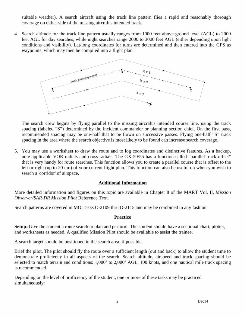
4. Search altitude for the track line pattern usually ranges from 1000 feet above ground level (AGL) to 2000
feet AGL for day searches, while night searches range 2000 to 3000 feet AGL (either depending upon light conditions and visibility). Lat/long coordinates for turns are determined and then entered into the GPS as waypoints, which may then be compiled into a flight plan.
A C
B
Track of missing aircraft½ x S
½ x S
1 x S
The search crew begins by flying parallel to the missing aircraft's intended course line, using the track spacing (labeled “S”) determined by the incident commander or planning section chief. On the first pass, recommended spacing may be one-half that to be flown on successive passes. Flying one-half “S” track spacing in the area where the search objective is most likely to be found can increase search coverage.
5. You may use a worksheet to draw the route and to log coordinates and distinctive features. As a backup,
note applicable VOR radials and cross-radials. The GX-50/55 has a function called "parallel track offset" that is very handy for route searches. This function allows you to create a parallel course that is offset to the left or right (up to 20 nm) of your current flight plan. This function can also be useful on when you wish to search a 'corridor' of airspace.
Additional Information
More detailed information and figures on this topic are available in Chapter 8 of the MART Vol. II, Mission Observer/SAR-DR Mission Pilot Reference Text.
Search patterns are covered in MO Tasks O-2109 thru O-2115 and may be combined in any fashion.
Practice
Setup: Give the student a route search to plan and perform. The student should have a sectional chart, plotter, and worksheets as needed. A qualified Mission Pilot should be available to assist the trainee.
A search target should be positioned in the search area, if possible.
Brief the pilot. The pilot should fly the route over a sufficient length (out and back) to allow the student time to demonstrate proficiency in all aspects of the search. Search altitude, airspeed and track spacing should be selected to match terrain and conditions: 1,000’ to 2,000’ AGL, 100 knots, and one nautical mile track spacing is recommended.
Depending on the level of proficiency of the student, one or more of these tasks may be practiced simultaneously:
3 Dec14
Planning. All mission sorties must be thoroughly planned: this ensures the pilot and crew can accomplish the sortie objectives safely and precisely. Treat each sortie as if it were an actual mission. Each time the student practices a sortie she should assist the pilot in completing all required paperwork and WMIRS entries. The student should sign herself into the mission, receive her assignment from the pilot, assist the pilot in planning the sortie, and help complete the Planning and Briefing sections in WMIRS. Become familiar with the ORM, W&B, fuel assumptions, and information entered into WMIRS.
Preflight and pilot briefings. Ensure the student receives safety and mission briefings from the pilot. Perform safety assignments as directed (e.g., collision avoidance during taxi and in flight).
Equipment. To the extent possible, the student should operate the communications and navigation equipment. The student should set up and enter information into the equipment (especially the GPS) prior to taxi.
Initial training. Depending on the proficiency and skills of the student, the pilot may need to demonstrate all aspects of a route search with the student sitting in the right seat. This gives the student time to absorb the information and work on such skills as setting up, entering data, and using the navigational equipment.
For each practice sortie, watch for:
1) Proper setup of the navigational equipment, particularly the GPS. [Depending on whether or not the student has access to a GPS simulator, the pilot may fly the aircraft while the student practices setting up and entering information into the GPS. However, by the time the student is ready for evaluation he must be able to accurately enter the required information into the GPS.]
2) Stabilized entry into the search area. The aircraft should be at search altitude and airspeed at least two miles before entering the search area.
3) Safety. The student should demonstrate familiarity with her duties as MO and as Mission Commander. This includes:
• Assisting the pilot in avoiding collisions and obstacles during the critical phases of flight
• Assist in enforcing the sterile cockpit rules
• Maintain situational awareness at all times
• Assist in monitoring fuel status
• Monitor the electronic search devices aboard the aircraft and advise the pilot when making course corrections in response to ELT signal
• Keep mission base and/or high bird appraised of status
• Coordinate scanner assignments and ensure proper breaks for the scanners (including you). Monitor crew for fatigue and dehydration (ensure the crew drinks plenty of fluids)
• Maintain a chronological flight log of all observations of note, including precise locations, sketches and any other noteworthy information
• Depending on conditions, attend the debriefing with the mission pilot
• Keep track of assigned supplies and equipment
Evaluation Preparation
Setup: Give the student a route search to plan and perform. The student should have a sectional chart, plotter, and worksheets as needed. A qualified Mission Pilot/Evaluator should be available to assist the trainee during the planning and flying stages of the sortie.
A search target should be positioned in the search area, if possible.
4 Dec14
Brief the pilot. The pilot should fly the pattern long enough to allow the student time to demonstrate proficiency in all aspects of the search. Search altitude, airspeed and track spacing should be selected to match terrain and conditions: 1,000’ to 2,000’ AGL and 100 knots.
Run the sortie as it would be during an actual mission. Have the student sign in, sign in the aircraft, and complete all required paperwork. Brief and debrief the sortie as if you were the Briefing/Debriefing Officer during a mission. [Note: This sortie may be accomplished with a Mission Pilot using the Approved Mission Pilot Proficiency Flight Profile #1, Visual Search Mission Profile (A12 or B12 in WMIRS).]
Brief Student: You are a Mission Observer trainee asked to assist a Mission Pilot in planning and performing a route search.
Evaluation
Performance measures Results
1. Sign into the mission. P F
2. Receive a sortie briefing, asking questions as necessary. P F
3. Assist in planning a route search from Point A to B and back. Include: P F
a. Position coordinates for the route (lat/long and VOR radials/cross-radials).
b. Altitude restrictions, obstacles and other hazards (e.g., MTRs and SUAs).
c. Scanner assignments (discuss as necessary).
4. Assist in completing the Planning and Briefing sections in WMIRS. P F
5. Receive pilot safety and mission briefings, asking questions as necessary. P F
6. Demonstrate and discuss safety during each critical phase of the flight. In particular, demonstrate collision avoidance and enforce sterile cockpit rules. P F
7. Demonstrate proper ATC communications, as applicable. P F
8. Setup the CAP FM radio and perform all required radio reports (may be simulated). P F
9. Assist in a route search. Demonstrate: P F
a. Proper use of navaids (GPS as primary; VOR as backup).
b. Proper use of radios (ATC as required, and CAP FM radio reports).
c. Proper scanner assignment (may be simulated).
d. Ability to spot the search target (if applicable).
e. Knowledge of MO and Mission Commander duties during the sortie.
10. Ensure the aircraft is secured at the end of the sortie (ready for next sortie). P F
11. Assist in completing the Debriefing section in WMIRS and debrief the sortie. P F
Student must receive a pass on all performance measures to qualify in this task. If the individual fails any measure, show what was done wrong and how to do it correctly.
1 Dec14
MO O-2110 ASSIST IN PLANNING AND PERFORMING A PARALLEL SEARCH
CONDITIONS
You are a Mission Observer trainee and must assist a Mission Pilot in planning and performing a parallel track search.
OBJECTIVES
Assist a Mission Pilot in planning and performing a parallel track search.
TRAINING AND EVALUATION
Training Outline 1. As a Mission Observer trainee, the ability to assist the Mission Pilot in planning and performing a parallel
track search pattern is essential. The observer learns to plan the search pattern in order to better assist the mission pilot and to more effectively direct scanners.
2. General. Because of the accuracy and reliability of the present Global Positioning System and GPS
receivers, CAP aircrews are now able to navigate and fly search patterns with unprecedented effectiveness and ease. The GPS has become the primary instrument for CAP air missions, and it is vital that observers know how to setup and use the GPS. However, observers must also be familiar with the other navigational instruments onboard CAP aircraft: these instruments complement the GPS and serve as backups in case of GPS receiver problems.
The MO (as Mission Commander) must be aware of how many scanners will be on board in order to assign which side of the aircraft they should scan. Planning and executing a search pattern with only one scanner on board is quite different from one where you have two scanners. Likewise, having an observer and two scanners on board will allow the observer to spend more time assisting the pilot without seriously decreasing search effectiveness. When you are planning and flying search patterns, always perform a stupid check -- as in "Hey! Wait a minute. This is stupid." Use this to see if your headings, waypoint positions, lat/long coordinates and distances look sensible. At a minimum, perform this check after you finish planning, when you start your pattern, and periodically thereafter. For example, you've just entered a set of lat/long coordinates into the GPS and turned to the heading shown on the GPS. You know the coordinates represent a lake southwest of your position, so check the heading indicator to see you're actually traveling in a southwesterly direction. Or, you know the lake is approximately 25 miles away; check the distance indicated on the GPS! You'd be surprised how many mistakes this method will catch. Pre-planning (plotting) your search pattern results in the most effective search. Pre-planning sets the details of the sortie in your mind and makes entering your data (correctly) into the GPS much easier. This allows the pilot and observer to concentrate on their primary task by minimizing navaid setup time and reducing confusion. Worksheets can be used (see the Flight Guide, Attachment 2) to pre-plan your search patterns, but they are just one method.
3. Parallel track search pattern. The parallel track (sweep) search pattern is normally used when one or more of
the following conditions exist: a) the search area is large and fairly level, b) only the approximate location of the target is known, or c) uniform coverage is desired. This type of search is used to search a grid.
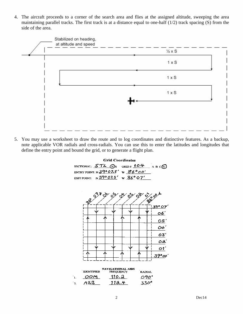
2 Dec14
4. The aircraft proceeds to a corner of the search area and flies at the assigned altitude, sweeping the area maintaining parallel tracks. The first track is at a distance equal to one-half (1/2) track spacing (S) from the side of the area.
5. You may use a worksheet to draw the route and to log coordinates and distinctive features. As a backup,
note applicable VOR radials and cross-radials. You can use this to enter the latitudes and longitudes that define the entry point and bound the grid, or to generate a flight plan.
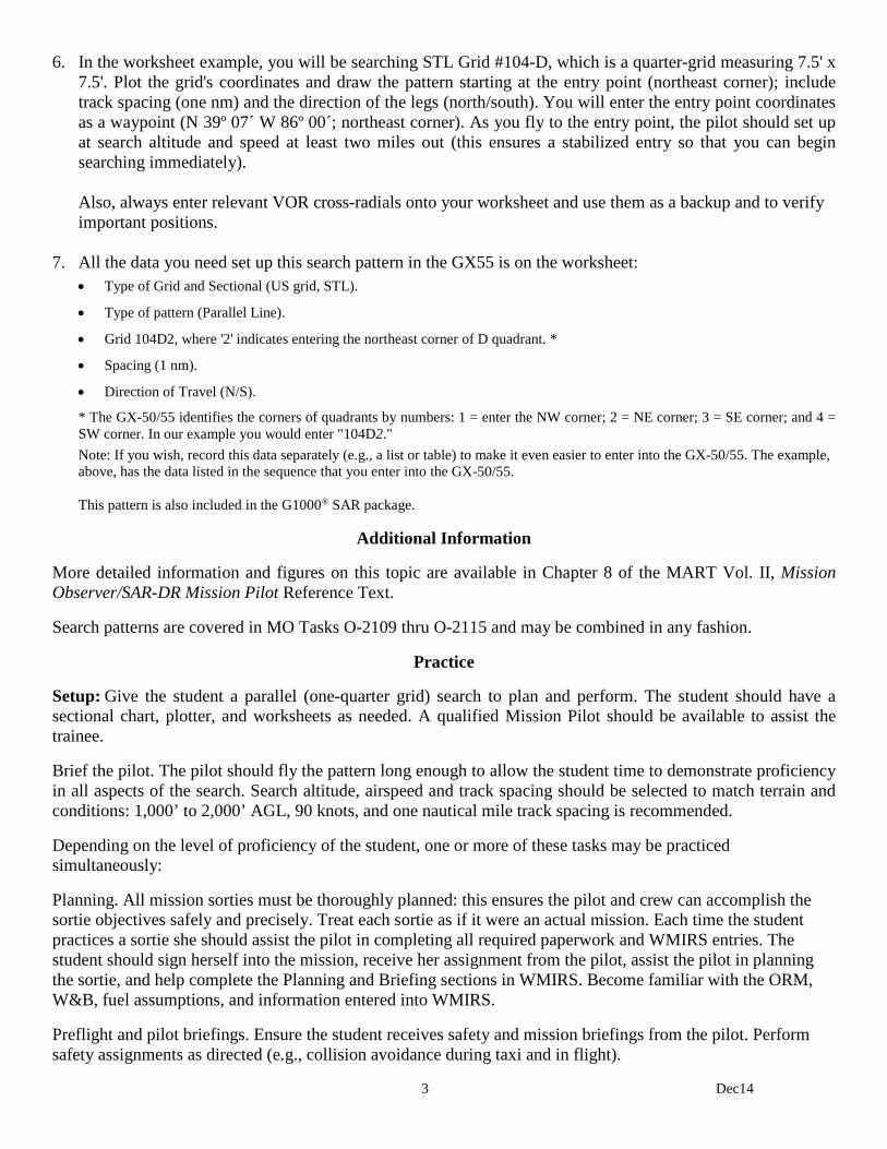
3 Dec14
6. In the worksheet example, you will be searching STL Grid #104-D, which is a quarter-grid measuring 7.5' x 7.5'. Plot the grid's coordinates and draw the pattern starting at the entry point (northeast corner); include track spacing (one nm) and the direction of the legs (north/south). You will enter the entry point coordinates as a waypoint (N 39º 07´ W 86º 00´; northeast corner). As you fly to the entry point, the pilot should set up at search altitude and speed at least two miles out (this ensures a stabilized entry so that you can begin searching immediately).
Also, always enter relevant VOR cross-radials onto your worksheet and use them as a backup and to verify important positions.
7. All the data you need set up this search pattern in the GX55 is on the worksheet:
• Type of Grid and Sectional (US grid, STL).
• Type of pattern (Parallel Line).
• Grid 104D2, where '2' indicates entering the northeast corner of D quadrant. *
• Spacing (1 nm).
• Direction of Travel (N/S).
* The GX-50/55 identifies the corners of quadrants by numbers: 1 = enter the NW corner; 2 = NE corner; 3 = SE corner; and 4 = SW corner. In our example you would enter "104D2." Note: If you wish, record this data separately (e.g., a list or table) to make it even easier to enter into the GX-50/55. The example, above, has the data listed in the sequence that you enter into the GX-50/55. This pattern is also included in the G1000® SAR package.
Additional Information
More detailed information and figures on this topic are available in Chapter 8 of the MART Vol. II, Mission Observer/SAR-DR Mission Pilot Reference Text.
Search patterns are covered in MO Tasks O-2109 thru O-2115 and may be combined in any fashion.
Practice
Setup: Give the student a parallel (one-quarter grid) search to plan and perform. The student should have a sectional chart, plotter, and worksheets as needed. A qualified Mission Pilot should be available to assist the trainee.
Brief the pilot. The pilot should fly the pattern long enough to allow the student time to demonstrate proficiency in all aspects of the search. Search altitude, airspeed and track spacing should be selected to match terrain and conditions: 1,000’ to 2,000’ AGL, 90 knots, and one nautical mile track spacing is recommended.
Depending on the level of proficiency of the student, one or more of these tasks may be practiced simultaneously:
Planning. All mission sorties must be thoroughly planned: this ensures the pilot and crew can accomplish the sortie objectives safely and precisely. Treat each sortie as if it were an actual mission. Each time the student practices a sortie she should assist the pilot in completing all required paperwork and WMIRS entries. The student should sign herself into the mission, receive her assignment from the pilot, assist the pilot in planning the sortie, and help complete the Planning and Briefing sections in WMIRS. Become familiar with the ORM, W&B, fuel assumptions, and information entered into WMIRS.
Preflight and pilot briefings. Ensure the student receives safety and mission briefings from the pilot. Perform safety assignments as directed (e.g., collision avoidance during taxi and in flight).

4 Dec14
Equipment. To the extent possible, the student should operate the communications and navigation equipment. The student should set up and enter information into the equipment (especially the GPS) prior to taxi.
Initial training. Depending on the proficiency and skills of the student, the pilot may need to demonstrate all aspects of a route search with the student sitting in the right seat. This gives the student time to absorb the information and work on such skills as setting up, entering data, and using the navigational equipment.
For each practice sortie, watch for:
1) Proper setup of the navigational equipment, particularly the GPS. [Depending on whether or not the student has access to a GPS simulator, the pilot may fly the aircraft while the student practices setting up and entering information into the GPS. However, by the time the student is ready for evaluation he must be able to accurately enter the required information into the GPS.]
2) Stabilized entry into the search area. The aircraft should be at search altitude and airspeed at least two miles before entering the search area.
3) Safety. The student should demonstrate familiarity with her duties as MO and as Mission Commander. This includes:
• Assisting the pilot in avoiding collisions and obstacles during the critical phases of flight
• Assist in enforcing the sterile cockpit rules
• Maintain situational awareness at all times
• Assist in monitoring fuel status
• Monitor the electronic search devices aboard the aircraft and advise the pilot when making course corrections in response to ELT signal
• Keep mission base and/or high bird appraised of status
• Coordinate scanner assignments and ensure proper breaks for the scanners (including you). Monitor crew for fatigue and dehydration (ensure the crew drinks plenty of fluids)
• Maintain a chronological flight log of all observations of note, including precise locations, sketches and any other noteworthy information
• Assist the pilot in completing the Debriefing section of a sortie in WMIRS
• Depending on conditions, attend the debriefing with the mission pilot
• Keep track of assigned supplies and equipment
Evaluation Preparation
Setup: Give the student a parallel track (one-quarter-grid) search to plan and perform. The student should have a sectional chart, plotter, and worksheets as needed. Brief the pilot on the task, if necessary. A qualified Mission Pilot/Evaluator should be available to assist the trainee during the planning and flying stages.
A search target should be positioned in the search area, if possible.
The pilot will enter and fly the grid long enough to allow the student to demonstrate proficiency in all aspects of the search. Search altitude, airspeed and track spacing should be selected to match terrain and conditions: 1,000’ AGL, 90 knots, and one nautical mile track spacing is recommended.
5 Dec14
Run the sortie as it would be during an actual mission. Have the student sign in, sign in the aircraft, and complete all required paperwork. Brief the sortie as if you were the Briefing Officer during a mission. [Note: This sortie may be accomplished with a Mission Pilot using the Approved Mission Pilot Proficiency Flight Profile #1, Visual Search Mission Profile (A12 or B12 in WMIRS).]
Brief Student: You are a Mission Observer trainee asked to assist a Mission Pilot in planning and performing a parallel track (one-quarter grid) search.
Evaluation
Performance measures Results
1. Sign into the mission. P F
2. Receive a sortie briefing, asking questions as necessary. P F
3. Assist in planning a one-quarter grid search. Include: P F
a. Position coordinates for the entry and exit points (lat/long & VOR radials/cross-radials).
b. Position coordinates for the legs (lat/long and VOR radials/cross-radials).
c. Altitude restrictions, obstacles and other hazards (e.g., MTRs and SUAs).
d. Scanner assignments (discuss as necessary).
4. Assist in completing the Planning and Briefing sections in WMIRS. P F
5. Receive pilot safety and mission briefings, asking questions as necessary. P F
6. Demonstrate and discuss safety during each critical phase of the flight. In particular, demonstrate collision avoidance and enforce sterile cockpit rules. P F
7. Demonstrate proper ATC communications. P F
8. Setup the CAP FM radio and perform all required radio reports (may be simulated). P F
9. Perform the grid search. Demonstrate: P F
a. Proper use of navaids (GPS as primary; VOR as backup).
b. Proper use of radios (ATC as required, and CAP FM radio reports).
c. Proper scanner assignment (may be simulated).
d. Ability to spot the search target (if applicable).
10. Ensure the aircraft is secured at the end of the sortie (ready for next sortie). P F
11. Assist in completing the Debriefing section in WMIRS and debrief the sortie. P F
Student must receive a pass on all performance measures to qualify in this task. If the individual fails any measure, show what was done wrong and how to do it correctly.
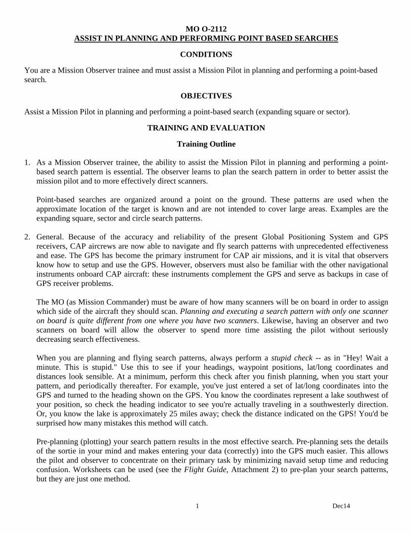
1 Dec14
MO O-2112 ASSIST IN PLANNING AND PERFORMING POINT BASED SEARCHES
CONDITIONS
You are a Mission Observer trainee and must assist a Mission Pilot in planning and performing a point-based search.
OBJECTIVES
Assist a Mission Pilot in planning and performing a point-based search (expanding square or sector).
TRAINING AND EVALUATION
Training Outline 1. As a Mission Observer trainee, the ability to assist the Mission Pilot in planning and performing a point-
based search pattern is essential. The observer learns to plan the search pattern in order to better assist the mission pilot and to more effectively direct scanners.
Point-based searches are organized around a point on the ground. These patterns are used when the approximate location of the target is known and are not intended to cover large areas. Examples are the expanding square, sector and circle search patterns.
2. General. Because of the accuracy and reliability of the present Global Positioning System and GPS
receivers, CAP aircrews are now able to navigate and fly search patterns with unprecedented effectiveness and ease. The GPS has become the primary instrument for CAP air missions, and it is vital that observers know how to setup and use the GPS. However, observers must also be familiar with the other navigational instruments onboard CAP aircraft: these instruments complement the GPS and serve as backups in case of GPS receiver problems.
The MO (as Mission Commander) must be aware of how many scanners will be on board in order to assign which side of the aircraft they should scan. Planning and executing a search pattern with only one scanner on board is quite different from one where you have two scanners. Likewise, having an observer and two scanners on board will allow the observer to spend more time assisting the pilot without seriously decreasing search effectiveness. When you are planning and flying search patterns, always perform a stupid check -- as in "Hey! Wait a minute. This is stupid." Use this to see if your headings, waypoint positions, lat/long coordinates and distances look sensible. At a minimum, perform this check after you finish planning, when you start your pattern, and periodically thereafter. For example, you've just entered a set of lat/long coordinates into the GPS and turned to the heading shown on the GPS. You know the coordinates represent a lake southwest of your position, so check the heading indicator to see you're actually traveling in a southwesterly direction. Or, you know the lake is approximately 25 miles away; check the distance indicated on the GPS! You'd be surprised how many mistakes this method will catch. Pre-planning (plotting) your search pattern results in the most effective search. Pre-planning sets the details of the sortie in your mind and makes entering your data (correctly) into the GPS much easier. This allows the pilot and observer to concentrate on their primary task by minimizing navaid setup time and reducing confusion. Worksheets can be used (see the Flight Guide, Attachment 2) to pre-plan your search patterns, but they are just one method.
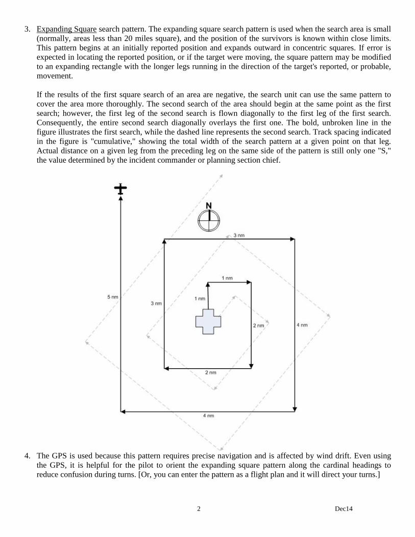
2 Dec14
3. Expanding Square search pattern. The expanding square search pattern is used when the search area is small (normally, areas less than 20 miles square), and the position of the survivors is known within close limits. This pattern begins at an initially reported position and expands outward in concentric squares. If error is expected in locating the reported position, or if the target were moving, the square pattern may be modified to an expanding rectangle with the longer legs running in the direction of the target's reported, or probable, movement.
If the results of the first square search of an area are negative, the search unit can use the same pattern to cover the area more thoroughly. The second search of the area should begin at the same point as the first search; however, the first leg of the second search is flown diagonally to the first leg of the first search. Consequently, the entire second search diagonally overlays the first one. The bold, unbroken line in the figure illustrates the first search, while the dashed line represents the second search. Track spacing indicated in the figure is "cumulative," showing the total width of the search pattern at a given point on that leg. Actual distance on a given leg from the preceding leg on the same side of the pattern is still only one "S," the value determined by the incident commander or planning section chief.
4. The GPS is used because this pattern requires precise navigation and is affected by wind drift. Even using
the GPS, it is helpful for the pilot to orient the expanding square pattern along the cardinal headings to reduce confusion during turns. [Or, you can enter the pattern as a flight plan and it will direct your turns.]

3 Dec14
5. You may use a worksheet to draw the pattern and to log coordinates and distinctive features. As a backup, note applicable VOR radials and cross-radials.
6. Fill the worksheet with the lat/longs that describe the expanding square. Starting at the entry point (e.g., a
483´ AGL tower), draw the square by going one mile north, then one mile east, then two miles south, and so on. You set it up this way because it is best to fly the square by first flying due north and then making all subsequent turns to the right; right turns are used because they allow the observer and scanner(s) to see the ground during the turns. You use cardinal headings because they are easiest for the pilot to fly. Length and width of the pattern may be modified to suit the requirements and conditions of the individual search.
Enter the lat/long of the starting point (N 38º 59´ W 86º 10´) into the GPS and save it as a waypoint. As you fly to the entry point, the pilot should set up at search altitude and speed at least two miles out (this ensures a stabilized entry so that you can begin searching immediately). The pilot should fly the pattern using the heading indicator and continuously displayed latitude and longitude on the GPS. Note: If the aircraft doesn't have an operable GPS the first leg should be flown directly into or directly with the wind. Every other leg will thus be affected by the wind in a relatively consistent manner.
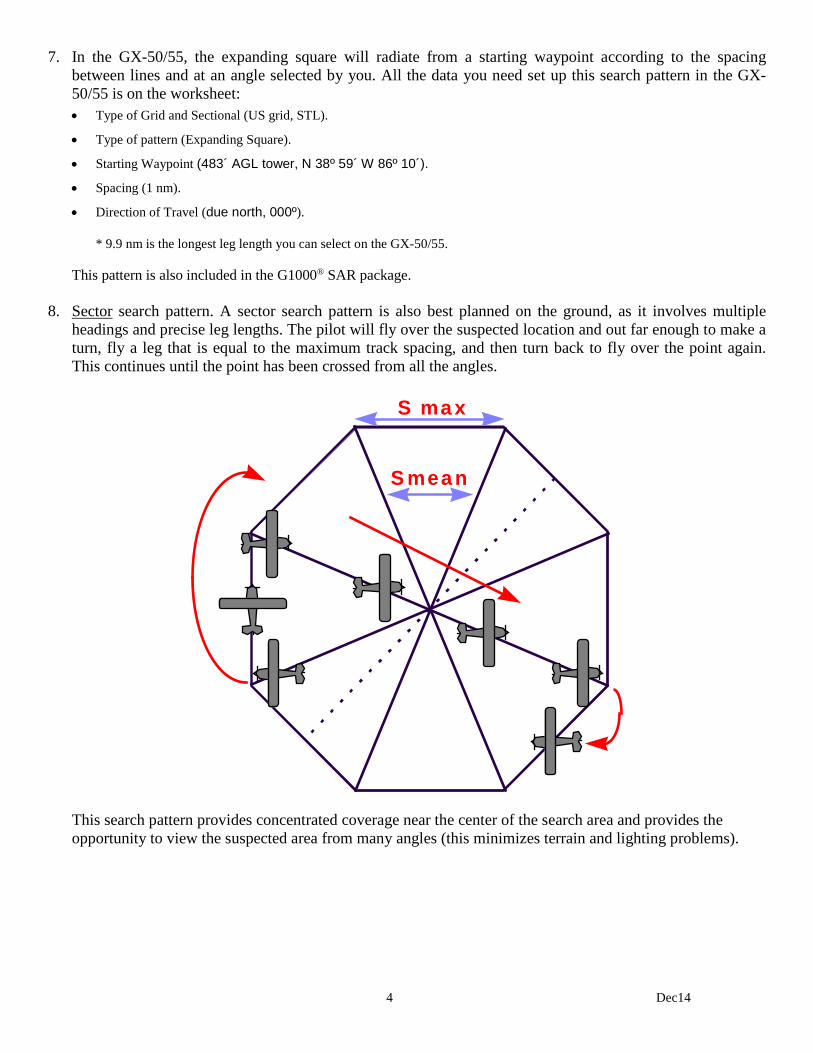
4 Dec14
7. In the GX-50/55, the expanding square will radiate from a starting waypoint according to the spacing between lines and at an angle selected by you. All the data you need set up this search pattern in the GX-50/55 is on the worksheet: • Type of Grid and Sectional (US grid, STL).
• Type of pattern (Expanding Square).
• Starting Waypoint (483´ AGL tower, N 38º 59´ W 86º 10´).
• Spacing (1 nm).
• Direction of Travel (due north, 000º).
* 9.9 nm is the longest leg length you can select on the GX-50/55.
This pattern is also included in the G1000® SAR package. 8. Sector search pattern. A sector search pattern is also best planned on the ground, as it involves multiple
headings and precise leg lengths. The pilot will fly over the suspected location and out far enough to make a turn, fly a leg that is equal to the maximum track spacing, and then turn back to fly over the point again. This continues until the point has been crossed from all the angles.
S max
S mean
This search pattern provides concentrated coverage near the center of the search area and provides the opportunity to view the suspected area from many angles (this minimizes terrain and lighting problems).
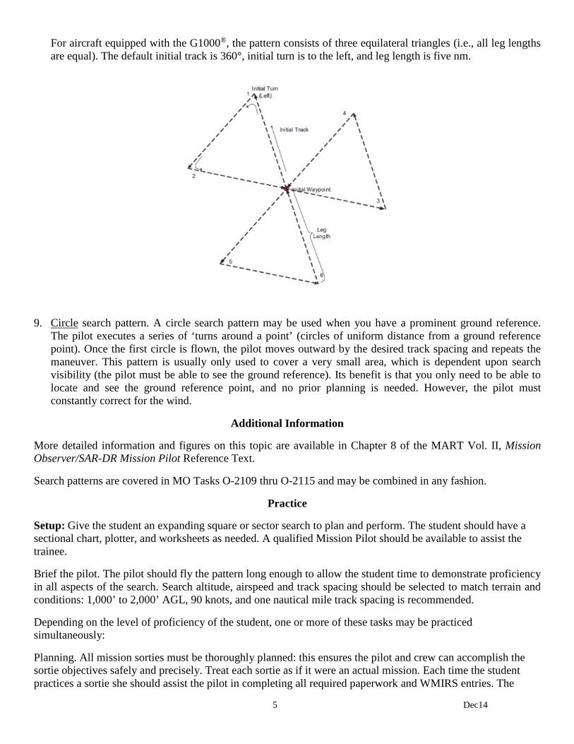
5 Dec14
For aircraft equipped with the G1000®, the pattern consists of three equilateral triangles (i.e., all leg lengths are equal). The default initial track is 360°, initial turn is to the left, and leg length is five nm.
9. Circle search pattern. A circle search pattern may be used when you have a prominent ground reference.
The pilot executes a series of ‘turns around a point’ (circles of uniform distance from a ground reference point). Once the first circle is flown, the pilot moves outward by the desired track spacing and repeats the maneuver. This pattern is usually only used to cover a very small area, which is dependent upon search visibility (the pilot must be able to see the ground reference). Its benefit is that you only need to be able to locate and see the ground reference point, and no prior planning is needed. However, the pilot must constantly correct for the wind.
Additional Information
More detailed information and figures on this topic are available in Chapter 8 of the MART Vol. II, Mission Observer/SAR-DR Mission Pilot Reference Text.
Search patterns are covered in MO Tasks O-2109 thru O-2115 and may be combined in any fashion.
Practice
Setup: Give the student an expanding square or sector search to plan and perform. The student should have a sectional chart, plotter, and worksheets as needed. A qualified Mission Pilot should be available to assist the trainee.
Brief the pilot. The pilot should fly the pattern long enough to allow the student time to demonstrate proficiency in all aspects of the search. Search altitude, airspeed and track spacing should be selected to match terrain and conditions: 1,000’ to 2,000’ AGL, 90 knots, and one nautical mile track spacing is recommended.
Depending on the level of proficiency of the student, one or more of these tasks may be practiced simultaneously:
Planning. All mission sorties must be thoroughly planned: this ensures the pilot and crew can accomplish the sortie objectives safely and precisely. Treat each sortie as if it were an actual mission. Each time the student practices a sortie she should assist the pilot in completing all required paperwork and WMIRS entries. The
6 Dec14
student should sign herself into the mission, receive her assignment from the pilot, assist the pilot in planning the sortie, and help complete the Planning and Briefing sections in WMIRS. Become familiar with the ORM, W&B, fuel assumptions, and information entered into WMIRS.
Preflight and pilot briefings. Ensure the student receives safety and mission briefings from the pilot. Perform safety assignments as directed (e.g., collision avoidance during taxi and in flight).
Equipment. To the extent possible, the student should operate the communications and navigation equipment. The student should set up and enter information into the equipment (especially the GPS) prior to taxi.
Initial training. Depending on the proficiency and skills of the student, the pilot may need to demonstrate all aspects of a route search with the student sitting in the right seat. This gives the student time to absorb the information and work on such skills as setting up, entering data, and using the navigational equipment.
For each practice sortie, watch for:
1) Proper setup of the navigational equipment, particularly the GPS. [Depending on whether or not the student has access to a GPS simulator, the pilot may fly the aircraft while the student practices setting up and entering information into the GPS. However, by the time the student is ready for evaluation he must be able to accurately enter the required information into the GPS.]
2) Stabilized entry into the search area. The aircraft should be at search altitude and airspeed at least two miles before entering the search area.
3) Safety. The student should demonstrate familiarity with her duties as MO and as Mission Commander. This includes:
• Assisting the pilot in avoiding collisions and obstacles during the critical phases of flight
• Assist in enforcing the sterile cockpit rules
• Maintain situational awareness at all times
• Assist in monitoring fuel status
• Monitor the electronic search devices aboard the aircraft and advise the pilot when making course corrections in response to ELT signal
• Keep mission base and/or high bird appraised of status
• Coordinate scanner assignments and ensure proper breaks for the scanners (including you). Monitor crew for fatigue and dehydration (ensure the crew drinks plenty of fluids)
• Maintain a chronological flight log of all observations of note, including precise locations, sketches and any other noteworthy information
• Depending on conditions, attend the debriefing with the mission pilot
• Keep track of assigned supplies and equipment

7 Dec14
Evaluation Preparation
Setup: Give the student an expanding square or sector search to plan and perform. The student should have a sectional chart, plotter, and worksheets as needed. A qualified Mission Pilot/Evaluator should be available to assist the trainee during the planning and flying stages.
A search target should be positioned in the search area, if possible.
The pilot will enter and fly the pattern long enough to allow the student to demonstrate proficiency in all aspects of the search. Search altitude, airspeed and track spacing should be selected to match terrain and conditions: 1,000’ AGL and 90 knots is recommended.
Run the sortie as it would be during an actual mission. Have the student sign in, sign in the aircraft, and complete all required paperwork. Brief and debrief the sortie as if you were the Briefing/Debriefing Officer during a mission. [Note: This sortie may be accomplished with a Mission Pilot using the Approved Mission Pilot Proficiency Flight Profile #1, Visual Search Mission Profile (A12 or B12 in WMIRS).]
Brief Student: You are a Mission Observer trainee asked to assist a Mission Pilot in planning and performing a point-based search.

8 Dec14
Evaluation
Performance measures Results
1. Sign into the mission. P F
2. Receive a sortie briefing, asking questions as necessary. P F
3. Assist in planning a point-based search (expanding square or sector). Include: P F
a. Estimated time enroute, time in the search area, and fuel requirements.
b. Position coordinates for the entry and exit points (lat/long & VOR radials/cross-radials).
c. Position coordinates for the legs (lat/long and VOR radials/cross-radials).
d. Altitude restrictions, obstacles and other hazards (e.g., MTRs and SUAs).
e. Scanner assignments (discuss as necessary).
4. Assist in completing the Planning and Briefing sections in WMIRS. P F
5. Receive pilot safety and mission briefings, asking questions as necessary. P F
6. Demonstrate and discuss safety during each critical phase of the flight. In particular, demonstrate collision avoidance and enforce sterile cockpit rules. P F
7. Demonstrate proper ATC communications. P F
8. Setup the CAP FM radio and perform all required radio reports (may be simulated). P F
9. Perform the point-based search (expanding square or sector). Demonstrate: P F
a. Proper use of navaids (GPS as primary; VOR as backup).
b. Proper use of radios (ATC as required, and CAP FM radio reports).
c. Proper scanner assignment (may be simulated).
d. Ability to spot the search target (if applicable).
10. Ensure the aircraft is secured at the end of the sortie (ready for next sortie). P F
11. Assist in completing the Debriefing section in WMIRS and debrief the sortie. P F
Student must receive a pass on all performance measures to qualify in this task. If the individual fails any measure, show what was done wrong and how to do it correctly.
1 Dec14
MO O-2115 ASSIST IN PLANNING AND PERFORMING A CREEPING LINE SEARCH
CONDITIONS
You are a Mission Observer trainee and must assist a Mission Pilot in planning and performing a creeping line search.
OBJECTIVES
Assist a Mission Pilot in planning and performing a creeping line search.
TRAINING AND EVALUATION
Training Outline 1. As a Mission Observer trainee, the ability to assist the Mission Pilot in planning and performing a creeping
line search pattern is essential. The observer learns to plan the search pattern in order to better assist the mission pilot and to more effectively direct scanners.
2. General. Because of the accuracy and reliability of the present Global Positioning System and GPS
receivers, CAP aircrews are now able to navigate and fly search patterns with unprecedented effectiveness and ease. The GPS has become the primary instrument for CAP air missions, and it is vital that observers know how to setup and use the GPS. However, observers must also be familiar with the other navigational instruments onboard CAP aircraft: these instruments complement the GPS and serve as backups in case of GPS receiver problems.
The MO (as Mission Commander) must be aware of how many scanners will be on board in order to assign which side of the aircraft they should scan. Planning and executing a search pattern with only one scanner on board is quite different from one where you have two scanners. Likewise, having an observer and two scanners on board will allow the observer to spend more time assisting the pilot without seriously decreasing search effectiveness. When you are planning and flying search patterns, always perform a stupid check -- as in "Hey! Wait a minute. This is stupid." Use this to see if your headings, waypoint positions, lat/long coordinates and distances look sensible. At a minimum, perform this check after you finish planning, when you start your pattern, and periodically thereafter. For example, you've just entered a set of lat/long coordinates into the GPS and turned to the heading shown on the GPS. You know the coordinates represent a lake southwest of your position, so check the heading indicator to see you're actually traveling in a southwesterly direction. Or, you know the lake is approximately 25 miles away; check the distance indicated on the GPS! You'd be surprised how many mistakes this method will catch. Pre-planning (plotting) your search pattern results in the most effective search. Pre-planning sets the details of the sortie in your mind and makes entering your data (correctly) into the GPS much easier. This allows the pilot and observer to concentrate on their primary task by minimizing navaid setup time and reducing confusion. Worksheets can be used (see the Flight Guide, Attachment 2) to pre-plan your search patterns, but they are just one method.
3. Creeping line search pattern. The creeping line search pattern is similar to the parallel patterns. The parallel
pattern search legs are aligned with the major, or longer, axis of the rectangular search areas, whereas the search legs of the creeping line pattern are aligned with the minor or shorter axis of rectangular search areas. The creeping line pattern is used when: a) the search area is narrow, long, and fairly level, b) the probable

2 Dec14
location of the target is thought to be on either side of the search track within two points, or c) there is a need for immediate coverage of one end of the search area.
4. The creeping line is a succession of search legs along a line. The starting point is located one-half search
track spacing inside the corner of the search area.
5. You may use a worksheet to draw the pattern and to log coordinates and distinctive features. As a backup,
note applicable VOR radials and cross-radials. [Note: You may also create a flight plan for the pattern.]
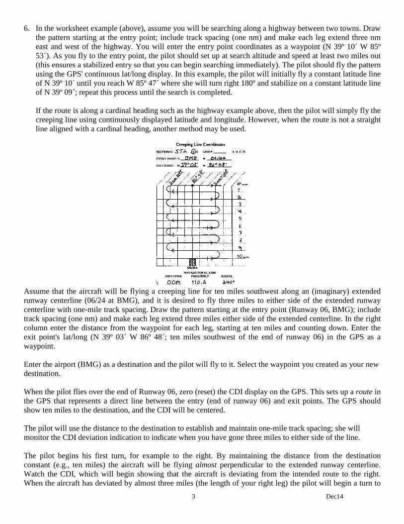
3 Dec14
6. In the worksheet example (above), assume you will be searching along a highway between two towns. Draw the pattern starting at the entry point; include track spacing (one nm) and make each leg extend three nm east and west of the highway. You will enter the entry point coordinates as a waypoint (N 39º 10´ W 85º 53´). As you fly to the entry point, the pilot should set up at search altitude and speed at least two miles out (this ensures a stabilized entry so that you can begin searching immediately). The pilot should fly the pattern using the GPS' continuous lat/long display. In this example, the pilot will initially fly a constant latitude line of N 39º 10´ until you reach W 85º 47´ where she will turn right 180º and stabilize on a constant latitude line of N 39º 09´; repeat this process until the search is completed.
If the route is along a cardinal heading such as the highway example above, then the pilot will simply fly the creeping line using continuously displayed latitude and longitude. However, when the route is not a straight line aligned with a cardinal heading, another method may be used.
Assume that the aircraft will be flying a creeping line for ten miles southwest along an (imaginary) extended runway centerline (06/24 at BMG), and it is desired to fly three miles to either side of the extended runway centerline with one-mile track spacing. Draw the pattern starting at the entry point (Runway 06, BMG); include track spacing (one nm) and make each leg extend three miles either side of the extended centerline. In the right column enter the distance from the waypoint for each leg, starting at ten miles and counting down. Enter the exit point's lat/long (N 39º 03´ W 86º 48´; ten miles southwest of the end of runway 06) in the GPS as a waypoint. Enter the airport (BMG) as a destination and the pilot will fly to it. Select the waypoint you created as your new destination. When the pilot flies over the end of Runway 06, zero (reset) the CDI display on the GPS. This sets up a route in the GPS that represents a direct line between the entry (end of runway 06) and exit points. The GPS should show ten miles to the destination, and the CDI will be centered. The pilot will use the distance to the destination to establish and maintain one-mile track spacing; she will monitor the CDI deviation indication to indicate when you have gone three miles to either side of the line. The pilot begins his first turn, for example to the right. By maintaining the distance from the destination constant (e.g., ten miles) the aircraft will be flying almost perpendicular to the extended runway centerline. Watch the CDI, which will begin showing that the aircraft is deviating from the intended route to the right. When the aircraft has deviated by almost three miles (the length of your right leg) the pilot will begin a turn to

4 Dec14
the left. The turn will be completed so that the aircraft will now be flying in the opposite direction at a distance of nine miles from the destination (the one-mile track spacing). Now watch as the CDI begins to return to center while maintaining a constant nine-mile distance from the destination. The pilot will continue as the CDI begins to deviate to the left, and the next turn (to the right) will begin as you approach a three-mile deviation. Continue this pattern until you have completed your search. Note: By using this technique you will actually be flying arcs instead of the usual squared (rectangular) legs. This is of little concern since the purpose is to cover the entire search area in a methodical manner. This method is very handy when you are assigned a creeping line while airborne. It's easy to plan, set up and perform once you have mastered the technique. You can also fly this pattern to search along a Victor airway. You can perform a similar pattern using the DME; it will be like flying a series of DME arcs. This method can also be used along a winding river or a road, but the pilot or observer must plan a line that roughly bisects the winding route and then vary the length of the legs as conditions warrant on the ground below. 7. In the GX-50/55, the creeping line is similar to the parallel line pattern, but the starting point is a selected
waypoint rather than a grid. The pattern will straddle the center of your flight plan. All the data you need set up this search pattern in the GX-50/55 is on the worksheet: • Type of Grid and Sectional (US grid, STL).
• Type of pattern (Creeping Line).
• Starting Waypoint (the airport, BMG).
• Spacing (1 nm).
• Direction of Travel (the runway heading, 060º).
• Leg Length (3 nm *).
• Start Side (Right).
* 9.9 nm is the longest leg length you can select on the GX-50/55.
Additional Information
More detailed information and figures on this topic are available in Chapter 8 of the MART Vol. II, Mission Observer/SAR-DR Mission Pilot Reference Text.
Search patterns are covered in MO Tasks O-2109 thru O-2115 and may be combined in any fashion.
Practice
Setup: Give the student an expanding square search to plan and perform. The student should have a sectional chart, plotter, and worksheets as needed. A qualified Mission Pilot should be available to assist the trainee.
Brief the pilot. The pilot should fly the pattern long enough to allow the student time to demonstrate proficiency in all aspects of the search. Search altitude, airspeed and track spacing should be selected to match terrain and conditions: 1,000’ to 2,000’ AGL, 90 knots, three mile legs, and one nautical mile track spacing is recommended.
5 Dec14
Depending on the level of proficiency of the student, one or more of these tasks may be practiced simultaneously:
Planning. All mission sorties must be thoroughly planned: this ensures the pilot and crew can accomplish the sortie objectives safely and precisely. Treat each sortie as if it were an actual mission. Each time the student practices a sortie she should assist the pilot in completing all required paperwork and WMIRS entries. The student should sign herself into the mission, receive her assignment from the pilot, assist the pilot in planning the sortie, and help complete the Planning and Briefing sections in WMIRS. Become familiar with the ORM, W&B, fuel assumptions, and information entered into WMIRS.
Preflight and pilot briefings. Ensure the student receives safety and mission briefings from the pilot. Perform safety assignments as directed (e.g., collision avoidance during taxi and in flight).
Equipment. To the extent possible, the student should operate the communications and navigation equipment. The student should set up and enter information into the equipment (especially the GPS) prior to taxi.
Initial training. Depending on the proficiency and skills of the student, the pilot may need to demonstrate all aspects of a route search with the student sitting in the right seat. This gives the student time to absorb the information and work on such skills as setting up, entering data, and using the navigational equipment.
For each practice sortie, watch for:
1) Proper setup of the navigational equipment, particularly the GPS. [Depending on whether or not the student has access to a GPS simulator, the pilot may fly the aircraft while the student practices setting up and entering information into the GPS. However, by the time the student is ready for evaluation he must be able to accurately enter the required information into the GPS.]
2) Stabilized entry into the search area. The aircraft should be at search altitude and airspeed at least two miles before entering the search area.
3) Safety. The student should demonstrate familiarity with her duties as MO and as Mission Commander. This includes:
• Assisting the pilot in avoiding collisions and obstacles during the critical phases of flight
• Assist in enforcing the sterile cockpit rules
• Maintain situational awareness at all times
• Assist in monitoring fuel status
• Monitor the electronic search devices aboard the aircraft and advise the pilot when making course corrections in response to ELT signal
• Keep mission base and/or high bird appraised of status
• Coordinate scanner assignments and ensure proper breaks for the scanners (including you). Monitor crew for fatigue and dehydration (ensure the crew drinks plenty of fluids)
• Maintain a chronological flight log of all observations of note, including precise locations, sketches and any other noteworthy information
• Depending on conditions, attend the debriefing with the mission pilot
• Keep track of assigned supplies and equipment
6 Dec14
Evaluation Preparation
Setup: Give the student a creeping line search to plan and perform. The student should have a sectional chart, plotter, and worksheets as needed. A qualified Mission Pilot/Evaluator should be available to assist the trainee during the planning and flying stages.
A search target should be positioned in the search area, if possible.
The pilot will enter and fly the pattern long enough to allow the student to demonstrate proficiency in all aspects of the search. Search altitude, airspeed and track spacing should be selected to match terrain and conditions: 1,000’ AGL, 90 knots, three mile legs, and one nautical mile track spacing is recommended.
Run the sortie as it would be during an actual mission. Have the student sign in, sign in the aircraft, and complete all required paperwork. Brief and debrief the sortie as if you were the Briefing/Debriefing Officer during a mission. [Note: This sortie may be accomplished with a Mission Pilot using the Approved Mission Pilot Proficiency Flight Profile #1, Visual Search Mission Profile (A12 or B12 in WMIRS).]
Brief Student: You are a Mission Observer trainee asked to assist a Mission Pilot in planning and performing a creeping line search.

7 Dec14
Evaluation
Performance measures Results
1. Sign into the mission. P F
2. Receive a sortie briefing, asking questions as necessary. P F
3. Assist in planning a creeping line search. Include: P F
a. Estimated time enroute, time in the search area, and fuel requirements.
b. Position coordinates for the entry and exit points (lat/long & VOR radials/cross-radials).
c. Position coordinates for the legs (lat/long and VOR radials/cross-radials).
d. Altitude restrictions, obstacles and other hazards (e.g., MTRs and SUAs).
e. Scanner assignments (discuss as necessary).
4. Assist in completing the Planning and Briefing sections in WMIRS. P F
5. Receive pilot safety and mission briefings, asking questions as necessary. P F
6. Demonstrate and discuss safety during each critical phase of the flight. In particular, demonstrate collision avoidance and enforce sterile cockpit rules. P F
7. Demonstrate proper ATC communications. P F
8. Setup the CAP FM radio and perform all required radio reports (may be simulated). P F
9. Perform the creeping line search. Demonstrate: P F
a. Proper use of navaids (GPS as primary; VOR as backup).
b. Proper use of radios (ATC as required, and CAP FM radio reports).
c. Proper scanner assignment (may be simulated).
d. Ability to spot the search target (if applicable).
10. Ensure the aircraft is secured at the end of the sortie (ready for next sortie). P F
11. Assist in completing the Debriefing section in WMIRS and debrief the sortie. P F
Student must receive a pass on all performance measures to qualify in this task. If the individual fails any measure, show what was done wrong and how to do it correctly.
1 Dec14
MO P-2007 DISCUSS MISSION OBSERVER DUTIES AND RESPONSIBILITIES
CONDITIONS
You are a Mission Observer trainee and must discuss observer duties and responsibilities.
OBJECTIVES
Discuss Observer duties and responsibilities.
TRAINING AND EVALUATION
Training Outline 1. As a Mission Observer trainee, understanding your duties and responsibilities is essential. The mission
observer has a key role in CAP missions, and has expanded duties that mainly pertain to assisting the mission pilot. This assistance may be in the planning phase, handling radio communications, assisting in navigation, and crew management (i.e., mission commander). The proficient observer makes it possible for the pilot to perform his duties with a greater degree of accuracy and safety by assuming these aspects of the workload.
2. The Observer's primary role while actually in a search area is that of scanner. 3. General duties and responsibilities include:
a. Depending on conditions, you may report with the mission pilot for briefing. Wear appropriate clothes for a mission.
b. Assist in planning the mission, and completing the Planning and Briefing sections of the sortie in WMIRS. The observer may act as Mission Commander for the sortie.
c. Assist in avoiding collisions and obstacles during taxiing. d. Assist in setting up and operating aircraft and CAP radios. e. Assist in setting up and operating aircraft navigational equipment (e.g., VORs and GPS). f. Assist enforcing the sterile cockpit rules. g. Maintain situational awareness at all times. h. Assist in monitoring fuel status. i. Monitor the electronic search devices aboard the aircraft and advise the pilot when making course
corrections in response to ELT signals. j. Keep mission base and/or high bird appraised of status. k. Coordinate scanner assignments and ensure proper breaks for the scanners (including yourself). Monitor
crew for fatigue and dehydration (ensure the crew drinks plenty of fluids). l. Maintain a chronological flight log of all observations of note, including precise locations, sketches and
any other noteworthy information. m. Assist in completing the Debriefing section of the sortie in WMIRS, Depending on conditions, attend
the debriefing with the mission pilot. n. Keep track of assigned supplies and equipment. o. Ensure that the air crew obtains sufficient rest during crew rest periods, including approval of extensions
to the maximum air crew duty period.
2 Dec14
4. Sterile Cockpit Rules a. The “Sterile Cockpit” concept recognizes that flight operations other than routine cruise flight are
intrinsically more hazardous and require the undivided and vigilant attention of all crewmembers. Non-essential conversations and activities not directly related to the operation of the aircraft and its mission are inappropriate.
b. The Pilot in Command (PIC) is responsible to ensure that these non-essential conversations, activities,
and otherwise distracting actions do not occur during those sections of the flight that are considered critical. Examples of critical sections of flight would be taxi, takeoff, climb and departure, operating in the search area, and arrival, descent and landing. Operations in high-density traffic areas or heavy ATC periods would also be considered critical.
c. The simplest way to ensure that all crewmembers and passengers are aware of this requirement is to
conduct a crew and passenger briefing prior to boarding the aircraft or prior to engine start. The Sterile Cockpit brief can be as simple as a general statement by the PIC indicating that an announcement will be made when the flight is in a critical phase of flight, or possibly, a detailed briefing of the various phases of flight that are considered busiest and critical for the crewmembers to avoid distractions.
d. It is essential that the PIC include in the sterile cockpit brief a statement that safety of flight items are
always appropriate to be brought to the immediate attention of the PIC. Safety concerns would be such items as potentially conflicting traffic, or potential mechanical problems with the aircraft (i.e., electrical smoke or smoke of an unknown origin, and leaking fuel).
Security CAP resources should be considered National Security assets. In times of emergency you should take special security precautions to protect the aircraft and crew. Some examples are: • Hangar the aircraft whenever possible. You may place small pieces of clear tape on fuel caps, the
cowling and/or doors that will break if someone tampers with vital areas. • Pay particular attention during preflight inspections. Look for signs of tampering and carefully inspect
the fuel for contamination. • Be as "low key" as possible, and be discrete. Don't discuss CAP business in public places. • Be aware of your surroundings at all times. If you see something or someone that is suspicious, don't
ignore it. Report your suspicions to your supervisor and/or law enforcement. 5. Once team members have been briefed on the mission and accomplished the necessary planning, observers
determine that all necessary equipment is aboard the airplane. Checklists help ensure that all essential equipment is included, and vary according to geographic location, climate, and terrain of the search area. Items on the observer's checklist should include CAP membership and specialty qualification cards, current charts and maps of the search area, flashlights, notebook and pencils, binoculars, and survival gear (prohibited items, such as firearms, should be listed too, to ensure none is included). A camera may be included to assist in describing the location and condition of the search objective or survivors. Unnecessary items or personal belongings should be left behind. The mission observer also assists the pilot in ensuring that all equipment aboard the search aircraft is properly stowed. An unsecured item can injure the crew or damage the aircraft in turbulence.
6. Once airborne, the observer provides navigation and communication assistance, allowing the pilot to
precisely fly the aircraft with a greater degree of safety. The observer also assists in enforcing sterile cockpit rules when necessary. In flight, particularly the transit phase, the observer maintains situational awareness in order to help ensure crew safety.

3 Dec14
7. The mission observer divides and assigns scanning responsibilities during her mission observer briefing, and ensures each scanner performs their assigned duty during flight. She monitors the duration of scanner activity, and enables the scanners to rest in order to minimize fatigue.
8. Observer Log. The observer must become proficient in using an in-flight navigational log. A complete
chronological log should be maintained from take-off until landing, and should include all events and sightings. Skill in maintaining the log requires training and experience. Remember, proficiency and confidence are gained through practice and application. It is important to log the geographical location of the search aircraft at the time of all events and sightings (as a habit, always log the Hobbs time each time you make a report or record an event or sighting). This information is entered into the Debriefing section of the sortie in WMIRS, which is reviewed by the incident commander and general staff. This data becomes a part of the total information that is the basis for subsequent actions and reports. Good logs give the staff a better picture of how the mission is progressing. If sketches or maps are made to compliment a sighting, note this and attach them to the log. Maps and sketches should be uploaded into the sortie (WMIRS).
Additional Information
More detailed information on this topic is available in Chapter 1 and Attachment 2 of the MART Vol. II, Mission Observer/SAR-DR Mission Pilot Reference Text.
Evaluation Preparation
Setup: Provide the student with a current copy of the Mission Observer/SAR-DR Mission Pilot Reference Text and an Observer log.
Brief Student: You are an Observer trainee asked about your duties and responsibilities, and to discuss the Observer's duties and responsibilities and Observer log.
Evaluation
Performance measures Results
1. State the primary role of the observer, particularly when in the search area. P F
2. Discuss general duties and responsibilities, including Sterile Cockpit rules. P F
3. Discuss basic airport security precautions. P F
4. Discuss pre-flight duties and responsibilities. P F
5. Discuss in-flight duties and responsibilities. P F
6. Discuss post-flight duties and responsibilities. P F
7. Discuss what should be entered into the Observer log. P F
Student must receive a pass on all performance measures to qualify in this task. If the individual fails any measure, show what was done wrong and how to do it correctly.

1 Dec14
MO P-2008 DISCUSS THE DANGERS OF ICING
CONDITIONS
You are a Mission Observer trainee and must discuss how icing occurs and associated dangers.
OBJECTIVES
Discuss how airframe and carburetor icing occur and their affects on aircraft performance.
TRAINING AND EVALUATION
Training Outline 1. As a Mission Observer trainee, knowing how icing forms and affects the aircraft is essential. 2. Frost. When the ground cools at night, the temperature of the air immediately adjacent to the ground is
frequently lowered to the saturation point, causing condensation. This condensation takes place directly upon objects on the ground as dew if the temperature is above freezing or as frost if the temperature is below freezing. Dew is of no importance to aircraft, but frost can be deadly. Normally we think of frost as unimportant - it forms on cars or other cold surfaces overnight, soon melting after the sun rises. However, frost on an airplane disturbs the airflow enough to reduce the lift and efficiency of aerodynamic surfaces. An airplane may be able to fly with frost on its wings, but, even with the airflow over the wings only slightly disrupted, controllability can become unpredictable. Frost should always be removed before flight. Some precautions should be taken if frost is expected, such as placing the aircraft in a hanger (even a T-hanger).
3. Airframe icing. There are only two fundamental requisites for ice formation on an aircraft in flight: first the
aircraft must be flying through visible water in the form of rain or cloud droplet, and second, when the liquid water droplets strike, their temperature or the temperature of the airfoil surface, must be 32º F. or below. Ice increases drag and decreases lift: an ice deposit of as little as one-half inch on the leading edge of a wing can reduce lift by about 50%, increase drag by an equal percentage, and thus greatly increase the stall speed. Ice deposits also increase weight (on a typical C172 a quarter-inch coating of ice can add up to 150 lbs., a half-inch can add 300 lbs., and an inch of clear ice can add 600 lbs.). Additionally, propeller efficiency is decreased.

2 Dec14
Sorties should never be flown in regions of possible icing. As altitude increases, temperature decreases at a fairly uniform rate of 2° Celsius or 3.6° Fahrenheit for each 1000 feet. This rate of temperature change is known as the lapse rate. At some altitude, the air temperature reaches the freezing temperature of water, and that altitude is known as the freezing level. You can estimate the freezing level prior to flight by using simple mathematics. For example, if the airport elevation is 1,000 feet and the temperature at ground level is 12° Celsius, the freezing level would be at approximately 6,000 feet above ground level (AGL) or 7,000 feet above mean sea level (MSL). Since the lapse rate is 2° per thousand feet, it would take 6,000 feet of altitude to go from 12° Celsius to 0°, the freezing temperature of water. The same technique works for Fahrenheit, but you use 3.6° for the lapse rate. Don’t forget to include the airport elevation in your computations -- altimeters are normally set to display MSL rather than AGL altitude. [This method yields a very approximate value for the freezing level. You are encouraged to leave a wide margin for error above and below this altitude if you must fly through visible moisture during a search.]
4. Carburetor icing. Unlike aircraft structural icing, carburetor ice can form on a warm day in moist air. In the
winter when temperatures are below 40º F. the air is usually too cold to contain enough moisture for carburetor ice to form. In the summer when temperatures are above 85º F. there is too much heat for ice to form. So, airplanes are most vulnerable to carburetor icing when operated in high humidity or visible moisture with temperatures between 45º and 85º F. It's most likely to become a problem when the aircraft is operated at low power settings, such as in descents and approaches to landings.
5. Taxiing in snow and ice can be dangerous. The pilot should never attempt to taxi through snow banks, and
should be very deliberate and careful while taxiing on snow or ice. Run-ups should be conducted in an area free of snow or ice, if possible. The observer (and scanner) must assist the pilot in these conditions, and be especially watchful for runway and taxiway boundaries and other obstacles that may be obscured by snow or ice.
Additional Information
More detailed information on this topic is available in Chapter 3 of the MART Vol. II, Mission Observer/SAR-DR Mission Pilot Reference Text.
Evaluation Preparation
Setup: None.
Brief Student: You are an Observer trainee asked to discuss icing.
Evaluation
Performance measures Results
1. Discuss the following concerning icing: P F
a. Freezing level.
b. How airframe frost and icing affects aircraft performance.
c. How carburetor icing affects aircraft performance.
Student must receive a pass on all performance measures to qualify in this task. If the individual fails any measure, show what was done wrong and how to do it correctly.
1 Dec14
MO P-2009 DISCUSS THE DANGERS OF REDUCED VISIBILITY CONDITIONS
CONDITIONS
You are a Mission Observer trainee and must discuss the causes and dangers of reduced visibility.
OBJECTIVES
Discuss the causes and dangers of reduced visibility and their effect on search operations.
TRAINING AND EVALUATION
Training Outline 1. As a Mission Observer trainee, basic knowledge of how reduced visibility conditions affect search
operations. 2. Reduced visibility conditions. One of the most common hazardous weather problems is loss of visibility.
This can happen either suddenly or very insidiously, depriving the pilot of his ability to see and avoid other aircraft, and reducing or depriving him altogether of his ability to control the aircraft, unless he has had training and is proficient in instrument flying. In reduced visibility, the crew's ability to see rising terrain and to avoid towers, power transmission lines, and other man-made obstacles is diminished. Visibility may be reduced by many conditions including clouds, rain, snow, fog, haze, smoke, blowing dust, sand, and snow. A similar condition called “white out” can occur where there has been snowfall.
Fog, especially dense fog, can make it extremely difficult, if not impossible, to see landing runways or areas. The crew should be alert for a potential problem with fog whenever the air is relatively still, the temperature and dew point are within several degrees, and the temperature is expected to drop further, as around sunset and shortly after sunrise. This is often a factor in delaying the first sorties of the day. Haze, a fine, smoke-like dust causes lack of transparency in the air. Its most often caused when still air prevents normal atmospheric mixing, allowing the particles to persist, instead of the wind's dispersing them. Like fog, it is most likely to occur when the air is still. When haze and smoke are present, the best measure a flight crew can take to minimize risk of such an encounter is to get a thorough weather briefing before flying, and update the briefing by radio with Flight Watch as required.
3. Effects. According to FAA regulations, under almost all circumstances flight using visual flight rules can
only be conducted with at least three miles of visibility. If clouds cover more than one-half the sky, the cloud bases must be no lower than 1,000 feet above the terrain. In addition, search aircraft must usually remain at least 500 feet below the cloud deck.
Each member of the aircrew must be vigilant during all phases of the flight when visibility is less than perfect. Crew resource management requires that each member of the crew be assigned an area to search during the takeoff, transit and approach-to-landing phases of the flight in order to help the pilot "see and avoid" obstacles and other aircraft. The aircrew must also characterize visibility in the search area so as to establish the proper scanning range: search visibility may be different than expected, and your search pattern may have to be adjusted accordingly. Be sure to cover this during your debriefing.
2 Dec14
Additional Information
More detailed information on this topic is available in Chapter 3 and Attachment 2 of the MART Vol. II, Mission Observer/SAR-DR Mission Pilot Reference Text.
Evaluation Preparation
Setup: None.
Brief Student: You are an Observer trainee asked to discuss reduced visibility conditions and their affect on search operations.
Evaluation
Performance measures Results
1. Discuss the following concerning reduced visibility conditions: P F
a. Reduced visibility conditions.
b. Basic reduced visibility minimums.
c. Effects on search operations.
Student must receive a pass on all performance measures to qualify in this task. If the individual fails any measure, show what was done wrong and how to do it correctly.
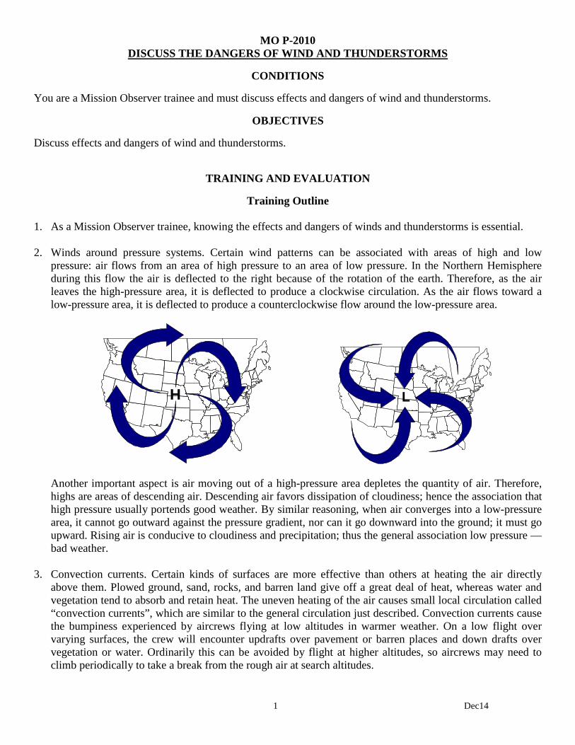
1 Dec14
MO P-2010 DISCUSS THE DANGERS OF WIND AND THUNDERSTORMS
CONDITIONS
You are a Mission Observer trainee and must discuss effects and dangers of wind and thunderstorms.
OBJECTIVES
Discuss effects and dangers of wind and thunderstorms.
TRAINING AND EVALUATION
Training Outline 1. As a Mission Observer trainee, knowing the effects and dangers of winds and thunderstorms is essential. 2. Winds around pressure systems. Certain wind patterns can be associated with areas of high and low
pressure: air flows from an area of high pressure to an area of low pressure. In the Northern Hemisphere during this flow the air is deflected to the right because of the rotation of the earth. Therefore, as the air leaves the high-pressure area, it is deflected to produce a clockwise circulation. As the air flows toward a low-pressure area, it is deflected to produce a counterclockwise flow around the low-pressure area.
H
L
Another important aspect is air moving out of a high-pressure area depletes the quantity of air. Therefore, highs are areas of descending air. Descending air favors dissipation of cloudiness; hence the association that high pressure usually portends good weather. By similar reasoning, when air converges into a low-pressure area, it cannot go outward against the pressure gradient, nor can it go downward into the ground; it must go upward. Rising air is conducive to cloudiness and precipitation; thus the general association low pressure — bad weather.
3. Convection currents. Certain kinds of surfaces are more effective than others at heating the air directly
above them. Plowed ground, sand, rocks, and barren land give off a great deal of heat, whereas water and vegetation tend to absorb and retain heat. The uneven heating of the air causes small local circulation called “convection currents”, which are similar to the general circulation just described. Convection currents cause the bumpiness experienced by aircrews flying at low altitudes in warmer weather. On a low flight over varying surfaces, the crew will encounter updrafts over pavement or barren places and down drafts over vegetation or water. Ordinarily this can be avoided by flight at higher altitudes, so aircrews may need to climb periodically to take a break from the rough air at search altitudes.

2 Dec14
Convection currents also cause difficulty in making landings, since they affect the rate of descent. The figures below show what happens to an aircraft on a landing approach over two different terrain types. The pilot must constantly correct for these affects during the final approach to the airport.
4. Cold and warm fronts. Certain characteristics of frontal activities will affect search effectiveness (primarily
visibility and turbulence). For the aircrew, these factors must be considered during mission planning.
Characteristics of a cold, unstable air mass are: Cumulus and cumulonimbus clouds Unlimited ceilings (except during precipitation) Excellent visibility (except during precipitation) Unstable air resulting in pronounced turbulence in lower levels (because of convention currents) Occasional local thunderstorms or showers - hail sleet, snow flurries Characteristics of a warm, stable air mass are: Stratus and stratocumulus clouds Generally low ceilings Poor visibility (fog, haze, smoke, and dust held in lower levels) Smooth, stable air with little or no turbulence Slow steady precipitation or drizzle
5. Windshear. Windshear is best described as a change in wind direction and/or speed within a very short
distance in the atmosphere. Under certain conditions, the atmosphere is capable of producing some dramatic shears very close to the ground; for example, wind direction changes of 180º and speed changes of 50 knots or more within 200 ft. of the ground have been observed. This, however, is unusual. Turbulence may or may not exist in wind shear conditions. If the surface wind under the front is strong and gusty there will be some turbulence associated with wind shear.
6. Thunderstorms. A thunderstorm is any storm accompanied by thunder and lighting. It usually includes some
form of precipitation, and can cause trouble for aircraft in many forms: turbulence, icing, poor visibility, hail, wind shear, microbursts, lightning, and, in severe cases, tornadoes. No thunderstorm should ever be taken lightly. During the cumulus stage, vertical growth occurs so quickly that climbing over the developing thunderstorm is not possible. Flight beneath a thunderstorm, especially in the mature stage, is considered very foolish, due to the violent down drafts and turbulence beneath them. Flight around them may be a
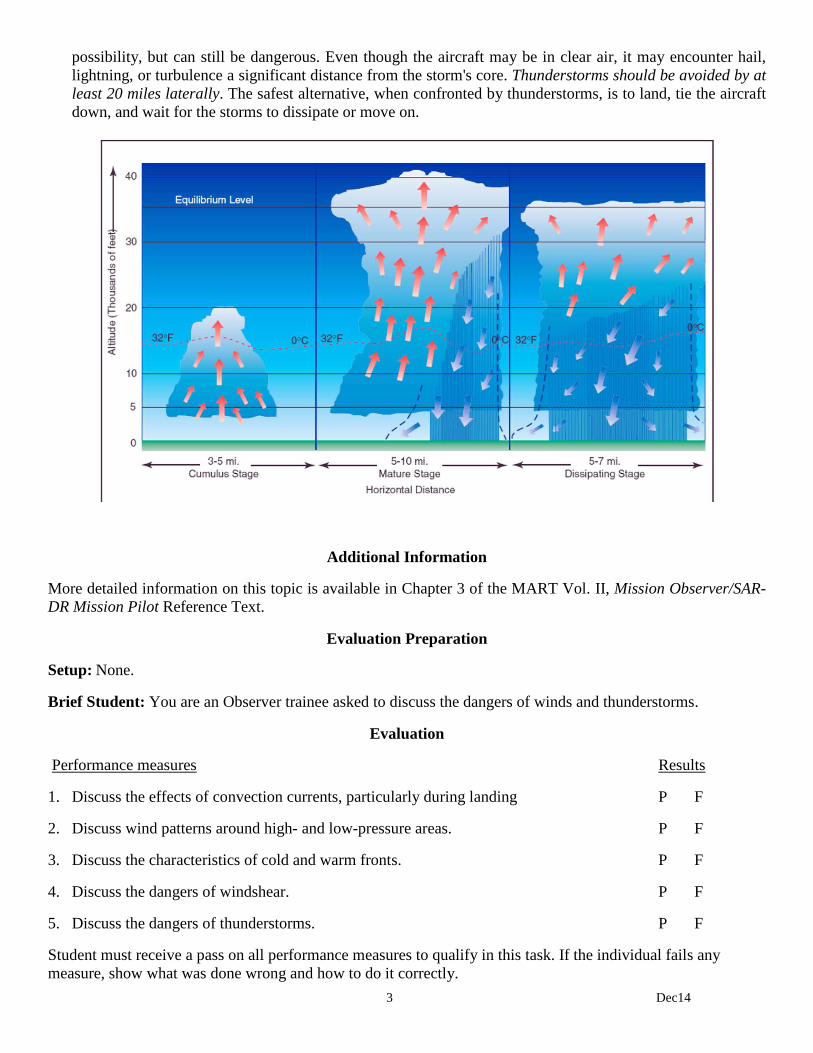
3 Dec14
possibility, but can still be dangerous. Even though the aircraft may be in clear air, it may encounter hail, lightning, or turbulence a significant distance from the storm's core. Thunderstorms should be avoided by at least 20 miles laterally. The safest alternative, when confronted by thunderstorms, is to land, tie the aircraft down, and wait for the storms to dissipate or move on.
Additional Information
More detailed information on this topic is available in Chapter 3 of the MART Vol. II, Mission Observer/SAR-DR Mission Pilot Reference Text.
Evaluation Preparation
Setup: None.
Brief Student: You are an Observer trainee asked to discuss the dangers of winds and thunderstorms.
Evaluation
Performance measures Results
1. Discuss the effects of convection currents, particularly during landing P F
2. Discuss wind patterns around high- and low-pressure areas. P F
3. Discuss the characteristics of cold and warm fronts. P F
4. Discuss the dangers of windshear. P F
5. Discuss the dangers of thunderstorms. P F
Student must receive a pass on all performance measures to qualify in this task. If the individual fails any measure, show what was done wrong and how to do it correctly.

1 Dec14
MO P-2011 DISCUSS THE EFFECTS OF DENSITY ALTITUDE ON AIRCRAFT PERFORMANCE
CONDITIONS
You are a Mission Observer trainee and must discuss how density altitude affects aircraft performance.
OBJECTIVES
Describe the factors that are used to determine density altitude, and discuss the effect of high density altitude on aircraft performance and strategies to deal with high density altitudes during search operations.
TRAINING AND EVALUATION
Training Outline 1. As a Mission Observer trainee, knowing how density altitude affects aircraft performance is very helpful. 2. Atmospheric pressure. Pressure at a given point is a measure of the weight of the column of air above that
point. As altitude increases, pressure diminishes as the weight of the air column decreases. This decrease in pressure has a pronounced effect on flight. The aircraft's altimeter is sensitive to these changes in pressure, and displays this pressure as altitude. When the altimeter is set to the current reported altimeter setting it indicates the aircraft's height above mean sea level (MSL). [If a local altimeter setting is unavailable, pilots usually set the altimeter to indicate the airport's MSL elevation.]
Changes in pressure are registered in inches of mercury: the standard sea-level pressure is 29.92 inches at a standard temperature of 15º C (59º F). If CAP aircraft always operated at standard conditions, the altimeter would always be accurate. An aircraft with an indicated (on the altimeter) altitude of 5,000' MSL will really be 5000' above the ground (AGL). However, these standard conditions rarely exist because the density of the atmosphere is always changing as altitude and temperature changes. [The third factor - humidity - also effects density, but the effect is smaller and it’s very hard to determine.]
3. Pressure altitude. Pressure altitude is an altitude measured from the point at which an atmospheric pressure
of 29.92 inches of mercury is found. A good rule of thumb is that a 1,000' change of altitude results in a 1-inch (mercury) change on a barometer. Another way to determine pressure altitude is to enter 29.92 into the altimeter's window and read the resulting altitude indication.
4. Density altitude. When pressure altitude is corrected for non-standard temperature, density altitude can be
determined.
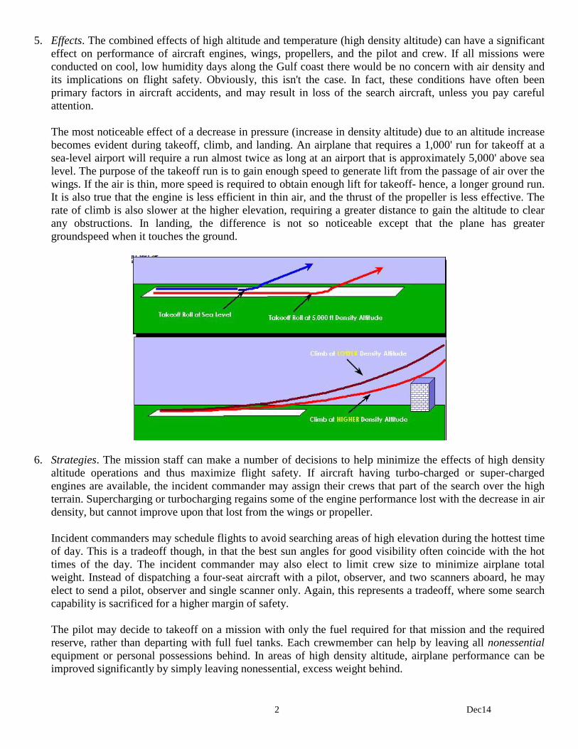
2 Dec14
5. Effects. The combined effects of high altitude and temperature (high density altitude) can have a significant effect on performance of aircraft engines, wings, propellers, and the pilot and crew. If all missions were conducted on cool, low humidity days along the Gulf coast there would be no concern with air density and its implications on flight safety. Obviously, this isn't the case. In fact, these conditions have often been primary factors in aircraft accidents, and may result in loss of the search aircraft, unless you pay careful attention.
The most noticeable effect of a decrease in pressure (increase in density altitude) due to an altitude increase becomes evident during takeoff, climb, and landing. An airplane that requires a 1,000' run for takeoff at a sea-level airport will require a run almost twice as long at an airport that is approximately 5,000' above sea level. The purpose of the takeoff run is to gain enough speed to generate lift from the passage of air over the wings. If the air is thin, more speed is required to obtain enough lift for takeoff- hence, a longer ground run. It is also true that the engine is less efficient in thin air, and the thrust of the propeller is less effective. The rate of climb is also slower at the higher elevation, requiring a greater distance to gain the altitude to clear any obstructions. In landing, the difference is not so noticeable except that the plane has greater groundspeed when it touches the ground.
6. Strategies. The mission staff can make a number of decisions to help minimize the effects of high density
altitude operations and thus maximize flight safety. If aircraft having turbo-charged or super-charged engines are available, the incident commander may assign their crews that part of the search over the high terrain. Supercharging or turbocharging regains some of the engine performance lost with the decrease in air density, but cannot improve upon that lost from the wings or propeller.
Incident commanders may schedule flights to avoid searching areas of high elevation during the hottest time of day. This is a tradeoff though, in that the best sun angles for good visibility often coincide with the hot times of the day. The incident commander may also elect to limit crew size to minimize airplane total weight. Instead of dispatching a four-seat aircraft with a pilot, observer, and two scanners aboard, he may elect to send a pilot, observer and single scanner only. Again, this represents a tradeoff, where some search capability is sacrificed for a higher margin of safety. The pilot may decide to takeoff on a mission with only the fuel required for that mission and the required reserve, rather than departing with full fuel tanks. Each crewmember can help by leaving all nonessential equipment or personal possessions behind. In areas of high density altitude, airplane performance can be improved significantly by simply leaving nonessential, excess weight behind.

3 Dec14
To help remember these conditions and their effects, an observer should remember the four "H's." Higher Humidity, Heat, or Height all result in reduced aircraft performance. Available engine power is reduced, climb capability is reduced, and takeoff and landing distances are increased.
7. Mountainous terrain. Aircrews flying the mountains must complete a course such as Mountain Fury.
When flying in mountainous areas it is recommended that flights be planned for early morning or late afternoon because heavy turbulence is often encountered in the afternoon, especially during summer. In addition, flying at the coolest part of the day reduces density altitude. Attempt to fly with as little weight as possible, but don't sacrifice fuel; in the event of adverse weather, the additional reserve could be a lifesaver. Study sectionals for altitudes required over the route and for obvious checkpoints. Prominent peaks, rivers and passes make excellent checkpoints. Be aware that mountain ranges have many peaks that may look the same to the untrained eye, so continually crosscheck your position with other landmarks and radio aids if possible. Also, the minimum altitude at which many radio aids are usable will be higher in the mountains. For that reason, low-frequency navigation, such as ADF, LORAN, or GPS tend to work best in the mountains. A weather check is essential for mountain flying. Ask specifically about winds aloft even when the weather is good. Expect winds above 10,000 feet to be prevailing westerlies in the mountain states. If winds aloft at your proposed altitude are above 30 knots, do not fly. Winds will be of much greater velocity in passes, and it will be more turbulent as well. Do not fly closer than necessary to terrain such as cliffs or rugged areas. Dangerous turbulence may be expected, especially when there are high winds (see figures, below). Crews must be constantly careful that a search never takes them over terrain that rises faster than the airplane can climb. Narrow valleys or canyons that have rising floors must be avoided, unless the aircraft can be flown from the end of higher elevation to the lower end, or the pilot is certain that the aircraft can climb faster than the terrain rises. Careful chart study by the crew prior to flight will help identify this dangerous terrain.
Additional Information
More detailed information on this topic is available in Chapter 4 of the MART Vol. II, Mission Observer/SAR-DR Mission Pilot Reference Text.
Evaluation Preparation
Setup: Provide the student with charts and/or a flight computer to compute density altitude.
Brief Student: You are an Observer trainee asked to calculate density altitude and discuss its effects.
4 Dec14
Evaluation
Performance measures Results
1. Discuss atmospheric pressure, pressure altitude and density altitude. P F
2. Obtain the local altimeter setting and enter it into an aircraft altimeter. P F
3. Discuss how high density altitude degrades aircraft performance. P F
4. Discuss strategies to deal with high density altitude on search operations. P F
5. OPTIONAL: Discuss mountainous terrain precautions and strategies.
Student must receive a pass on all performance measures to qualify in this task. If the individual fails any measure, show what was done wrong and how to do it correctly.
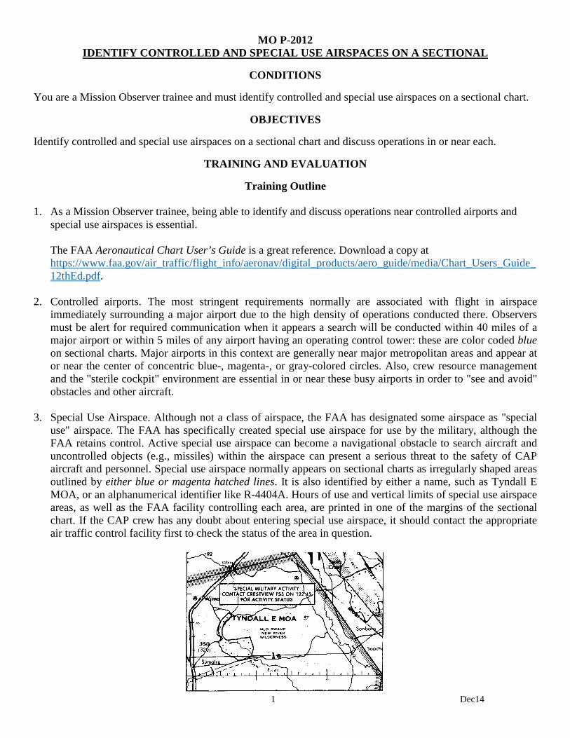
1 Dec14
MO P-2012 IDENTIFY CONTROLLED AND SPECIAL USE AIRSPACES ON A SECTIONAL
CONDITIONS
You are a Mission Observer trainee and must identify controlled and special use airspaces on a sectional chart.
OBJECTIVES
Identify controlled and special use airspaces on a sectional chart and discuss operations in or near each.
TRAINING AND EVALUATION
Training Outline 1. As a Mission Observer trainee, being able to identify and discuss operations near controlled airports and
special use airspaces is essential.
The FAA Aeronautical Chart User’s Guide is a great reference. Download a copy at https://www.faa.gov/air_traffic/flight_info/aeronav/digital_products/aero_guide/media/Chart_Users_Guide_12thEd.pdf.
2. Controlled airports. The most stringent requirements normally are associated with flight in airspace
immediately surrounding a major airport due to the high density of operations conducted there. Observers must be alert for required communication when it appears a search will be conducted within 40 miles of a major airport or within 5 miles of any airport having an operating control tower: these are color coded blue on sectional charts. Major airports in this context are generally near major metropolitan areas and appear at or near the center of concentric blue-, magenta-, or gray-colored circles. Also, crew resource management and the "sterile cockpit" environment are essential in or near these busy airports in order to "see and avoid" obstacles and other aircraft.
3. Special Use Airspace. Although not a class of airspace, the FAA has designated some airspace as "special
use" airspace. The FAA has specifically created special use airspace for use by the military, although the FAA retains control. Active special use airspace can become a navigational obstacle to search aircraft and uncontrolled objects (e.g., missiles) within the airspace can present a serious threat to the safety of CAP aircraft and personnel. Special use airspace normally appears on sectional charts as irregularly shaped areas outlined by either blue or magenta hatched lines. It is also identified by either a name, such as Tyndall E MOA, or an alphanumerical identifier like R-4404A. Hours of use and vertical limits of special use airspace areas, as well as the FAA facility controlling each area, are printed in one of the margins of the sectional chart. If the CAP crew has any doubt about entering special use airspace, it should contact the appropriate air traffic control facility first to check the status of the area in question.
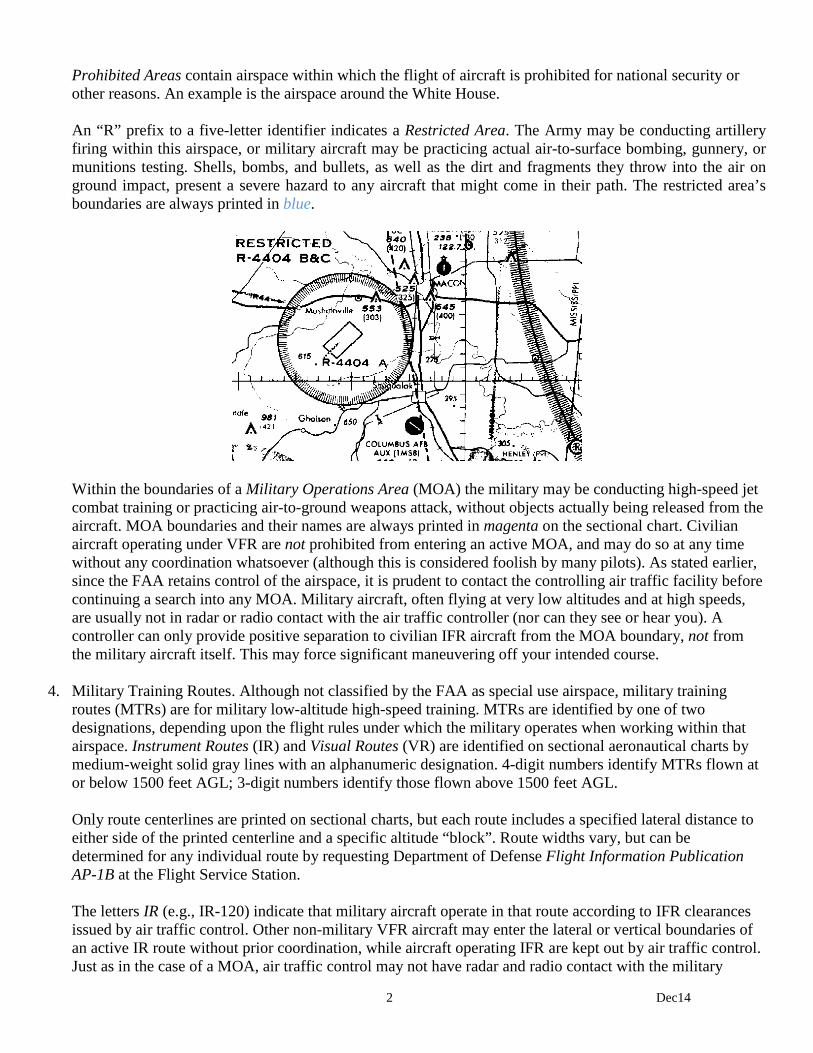
2 Dec14
Prohibited Areas contain airspace within which the flight of aircraft is prohibited for national security or other reasons. An example is the airspace around the White House. An “R” prefix to a five-letter identifier indicates a Restricted Area. The Army may be conducting artillery firing within this airspace, or military aircraft may be practicing actual air-to-surface bombing, gunnery, or munitions testing. Shells, bombs, and bullets, as well as the dirt and fragments they throw into the air on ground impact, present a severe hazard to any aircraft that might come in their path. The restricted area’s boundaries are always printed in blue.
Within the boundaries of a Military Operations Area (MOA) the military may be conducting high-speed jet combat training or practicing air-to-ground weapons attack, without objects actually being released from the aircraft. MOA boundaries and their names are always printed in magenta on the sectional chart. Civilian aircraft operating under VFR are not prohibited from entering an active MOA, and may do so at any time without any coordination whatsoever (although this is considered foolish by many pilots). As stated earlier, since the FAA retains control of the airspace, it is prudent to contact the controlling air traffic facility before continuing a search into any MOA. Military aircraft, often flying at very low altitudes and at high speeds, are usually not in radar or radio contact with the air traffic controller (nor can they see or hear you). A controller can only provide positive separation to civilian IFR aircraft from the MOA boundary, not from the military aircraft itself. This may force significant maneuvering off your intended course.
4. Military Training Routes. Although not classified by the FAA as special use airspace, military training
routes (MTRs) are for military low-altitude high-speed training. MTRs are identified by one of two designations, depending upon the flight rules under which the military operates when working within that airspace. Instrument Routes (IR) and Visual Routes (VR) are identified on sectional aeronautical charts by medium-weight solid gray lines with an alphanumeric designation. 4-digit numbers identify MTRs flown at or below 1500 feet AGL; 3-digit numbers identify those flown above 1500 feet AGL.
Only route centerlines are printed on sectional charts, but each route includes a specified lateral distance to either side of the printed centerline and a specific altitude “block”. Route widths vary, but can be determined for any individual route by requesting Department of Defense Flight Information Publication AP-1B at the Flight Service Station. The letters IR (e.g., IR-120) indicate that military aircraft operate in that route according to IFR clearances issued by air traffic control. Other non-military VFR aircraft may enter the lateral or vertical boundaries of an active IR route without prior coordination, while aircraft operating IFR are kept out by air traffic control. Just as in the case of a MOA, air traffic control may not have radar and radio contact with the military

3 Dec14
aircraft using the route. Therefore, it is necessary to provide separation between other IFR aircraft and the route airspace regardless of where the military aircraft may be located along the route. This may force either a route or altitude change. You can request the status of IR routes from the controlling air traffic facility. The letters VR (e.g., VR-1102) indicate that the military operates under VFR when operating within the lateral and vertical limits of that airspace. The see-and-avoid concept applies to all civilian and military aircraft operating there, and all crew members must be vigilant in visual lookout when within or near a VR training route. Many military missions go to and from visual training routes' start and exit points on IFR clearances and the prudent crew can inquire about the status of the route with air traffic control when operating through or near a VR training route.
You can determine scheduled military activity for restricted areas, MOAs, and military training routes by checking Notices to Airmen (NOTAMS) at the Flight Service Station. However, checking with the air traffic control facilities is preferable, since it will reveal actual, "real time" activity versus scheduled activity. When flying through any special use airspace or training route, crewmembers should be alert and cautious at all times, because incorrect or incomplete coordination between the military and the FAA is the rule rather than the exception.
Additional Information
More detailed information on this topic and examples are available in Chapter 5 of the MART Vol. II, Mission Observer/SAR-DR Mission Pilot Reference Text. Also, the FAA Aeronautical Chart User’s Guide is a great reference and can be downloaded for free.
Evaluation Preparation
Setup: Provide the student a sectional chart(s) containing controlled airports and all forms of special use airspaces.
Brief Student: You are an Observer trainee asked to identify (sectional) and discuss operations near controlled airports and special use airspaces.

4 Dec14
Evaluation
Performance measures Results
1. Identify (sectional) and discuss operations in and near, and identify on a sectional chart: P F
a. Controlled airport.
b. Prohibited airspace.
c. Restricted airspace.
d. Military Operating Area.
e. Military Training Routes.
Student must receive a pass on all performance measures to qualify in this task. If the individual fails any measure, show what was done wrong and how to do it correctly.


