433-OPS-0001 CHECK THE GLAST PROJECT WEBSITE AT http://glast.gsfc.nasa.gov/project/cm/mcdl TO VERIFY THAT THIS IS THE CORRECT VERSION PRIOR TO USE. GODDARD SPACE FLIGHT CENTER GREENBELT, MARYLAND Gamma-Ray Large Area Space Telescope (GLAST) Project Mission Operations Concept Document Version 1.0 Revision A May 24, 2003
Transcript
433-OPS-0001
CHECK THE GLAST PROJECT WEBSITE AT http://glast.gsfc.nasa.gov/project/cm/mcdl TO VERIFY THAT THIS IS THE CORRECT VERSION PRIOR TO USE.
GODDARD SPACE FLIGHT CENTER GREENBELT, MARYLAND
Gamma-Ray Large Area Space Telescope
(GLAST) Project
Mission Operations Concept Document
Version 1.0 Revision A
May 24, 2003
433-OPS-0001
ii
Document Approval Prepared by: __________________________ __________________________ John Nagy Date Mission Operations Systems Lead Approved by: __________________________ __________________________ Kevin Grady Date GLAST Project Manager __________________________ __________________________ Mike Rackley Date GLAST Ground System/Ops Manager Concurrence: __________________________ __________________________ Jonathan Ormes Date GLAST Project Scientist __________________________ __________________________ Peter Michelson Date Large Area Telescope Principal Investigator __________________________ __________________________ Charles Meegan Date GLAST Burst Monitor Principal Investigator
433-OPS-0001
iii
REVISION STATUS This document is controlled by the GLAST Ground Segment Project. Changes require prior approval of the GLAST Ground System/Ops Manager. VERSION DATE CHANGED BY DESCRIPTION
3.3 LAUNCH AND EARLY ORBIT CHECKOUT...................................................... 24 3.4 NORMAL OPERATIONS .................................................................................. 26
4.3 GLAST SCIENCE TEAM................................................................................... 40 4.4 WORKING GROUPS ........................................................................................ 41
APPENDIX A – ACRONYM LIST................................................................................. 43
1.0 INTRODUCTION 1.1 PURPOSE The purpose of this document is to establish an operations concept for the GLAST mission. The GLAST mission involves the 5-year operation of the GLAST spacecraft and instruments to perform gamma-ray measurements over the entire celestial sphere with a sensitivity of a factor of 30 or more than obtained by earlier space missions. This document describes the flight and ground operations activities, interfaces, and overall operations flow that support the requirements for GLAST mission planning, scheduling, commanding, monitoring, and science data delivery to the Science Support Center (SSC). It is intended as an introduction to GLAST mission operations to a range of users including science team members, sustaining engineering personnel, and management. While not a requirements document, the operations concepts described here will help guide the development of the GLAST Mission Operations Center (MOC) and interfaces to other elements of the GLAST Ground Segment. 1.2 SCOPE The scope of this document includes all operations-related plans for the implementation of the GLAST mission, specifically including the following: • Overviews of the science, spacecraft, instruments, and ground segment
operations • Flight operations activities including mission planning, commanding,
monitoring, flight dynamics support, Gamma Ray Burst (GRB) detection and notification, Targets of Opportunity (ToO) support, and sustaining engineering
• Operations organization, assigned responsibilities, and management 1.3 APPLICABLE DOCUMENTS The following documents were referenced during the development of this document. The reader is encouraged to use present and future versions of these documents for further research. Most of the documents are available on the GLAST Project web sites at http://glast.gsfc.nasa.gov/.
2.0 MISSION OVERVIEW GLAST scientific objectives will be satisfied by two instruments. The main instrument, the Large Area Telescope (LAT), will have superior area, angular resolution, field of view, and dead time that together with the GLAST Burst Monitor (GBM) will provide a factor of 30 or more advance in sensitivity, as well as provide capability for study of transient phenomena. The GBM will have a field of view several times larger than the LAT and will provide spectral coverage of gamma-ray bursts that extends from the lower limit of the LAT down to 10 keV. With the LAT and GBM, GLAST will be a flexible observatory for investigating the great range of astrophysical phenomena best studied in high-energy gamma rays. Spectrum Astro is responsible for the design and manufacture of the spacecraft, integration of the scientific instruments with the spacecraft, integration of the complete space vehicle/observatory with the Delta launch vehicle, and launch and early orbit activities. NASA/GSFC has program management responsibility. GLAST is an international collaboration of government agencies and academic institutions from the United States, France, Germany, Japan, Italy, and Sweden. The LAT is a joint project with NASA and the U.S. Department of Energy. The LAT will be constructed by Stanford University, the Stanford Linear Accelerator Center, the University of California, Santa Cruz, the Naval Research Laboratory, NASA Goddard Space Flight Center, and the international partners. The GBM is a joint project with Marshall Space Flight Center, the University of Alabama, and the Max-Planck Institute in Germany. The Italian Space Agency (ASI) is contributing the Malindi ground station in Kenya for spacecraft telemetry downlink and command uplink. Universal Space Network of Horsham, PA is also scheduled to support GLAST using their South Point, Hawaii ground station as a primary site for spacecraft telemetry downlink and command uplink. The GLAST spacecraft will be launched on a Boeing Delta II 2920H-10 vehicle from the Eastern Test Range (ETR), Florida. A launch date of September 2006 is currently scheduled. GLAST will then settle into an orbit at an altitude of 550 km and an inclination of 28.5 degrees, orbiting the Earth once every 96 minutes. Following a 60-day checkout period, the nominal 5-year science mission will commence. 2.1 GLAST SCIENCE OVERVIEW The high-energy gamma-ray universe is diverse and dynamic. Measuring the various characteristics of the many types of gamma-ray sources on timescales from milliseconds to years places demands on the GLAST mission. GLAST has the following specific scientific objectives:
1. Identify and study nature’s high-energy particle accelerators through observations of active galactic nuclei, GRBs, pulsars, stellar-mass black
433-OPS-0001
9
holes, supernova remnants, Solar and stellar flares, and the diffuse galactic and extragalactic high-energy background.
2. Use these sources to probe important physical parameters of the Galaxy and the Universe that are not readily measured with other observations, such as the intensity and distribution of intergalactic infrared radiation fields, magnetic field strengths in cosmic particle accelerators, diffuse gamma-ray fluxes from the Milky Way and nearby galaxies, and the diffuse extragalactic gamma-ray background radiation.
3. Use high-energy gamma rays to search for a variety of as yet undetected and/or new phenomena, such as particle dark matter and evaporating black holes.
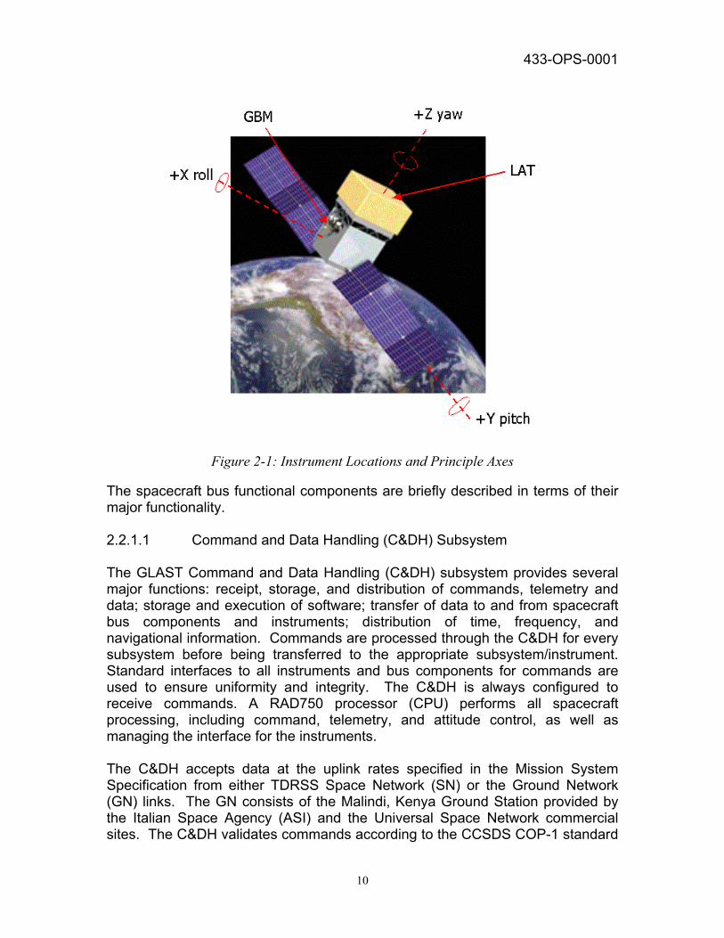
Because of its unique capabilities and the great increment in sensitivity it offers in a largely unexplored region of the electromagnetic spectrum, GLAST draws the interest of several scientific communities. The international high-energy astrophysics and high-energy particle physics communities together have been particularly active in developing the mission and the necessary technologies. 2.2 GLAST OBSERVATORY OVERVIEW 2.2.1 Spacecraft Overview The GLAST observatory comprises two major instruments and the spacecraft bus. Figure 2-1 locates the two instruments and defines the principal axes. The GLAST spacecraft provides the required structural, thermal, electrical, attitude control, propulsion1, and data/communications. Descriptions presented here do not represent the project requirements. Requirements are available in the documentation listed in Section 1.3.
1 The propulsion system may be removed from the GLAST mission if the requirement is deemed unnecessary.
433-OPS-0001
10
Figure 2-1: Instrument Locations and Principle Axes
The spacecraft bus functional components are briefly described in terms of their major functionality. 2.2.1.1 Command and Data Handling (C&DH) Subsystem The GLAST Command and Data Handling (C&DH) subsystem provides several major functions: receipt, storage, and distribution of commands, telemetry and data; storage and execution of software; transfer of data to and from spacecraft bus components and instruments; distribution of time, frequency, and navigational information. Commands are processed through the C&DH for every subsystem before being transferred to the appropriate subsystem/instrument. Standard interfaces to all instruments and bus components for commands are used to ensure uniformity and integrity. The C&DH is always configured to receive commands. A RAD750 processor (CPU) performs all spacecraft processing, including command, telemetry, and attitude control, as well as managing the interface for the instruments. The C&DH accepts data at the uplink rates specified in the Mission System Specification from either TDRSS Space Network (SN) or the Ground Network (GN) links. The GN consists of the Malindi, Kenya Ground Station provided by the Italian Space Agency (ASI) and the Universal Space Network commercial sites. The C&DH validates commands according to the CCSDS COP-1 standard
433-OPS-0001
11
for commands. Once commands are received and validated by the C&DH, they are either distributed immediately or stored for later execution. Real-time commands are distributed to the appropriate subsystem immediately after receipt and validation. Absolute time and relative time commands are recognized by the C&DH and stored for later execution. Both absolute time command loads and relative time command sequences can contain interleaved spacecraft bus and instrument commands. The C&DH uses standard protocols for the transfer of housekeeping, science, and other data. It receives housekeeping data, science data, and other information from the instruments and housekeeping data from the spacecraft bus components. All of the data is stored on-board for later transmission to the ground. The C&DH provides lower downlink rates for real-time data for use during safe mode or when communications links cannot support the housekeeping data downlink rate. The C&DH stores all data on-board for playback to the ground during the daily 5 - 7 GN contacts. The 96 Gbit Solid State Recorder (SSR) is internally redundant and will accommodate the average science data rates of 300 kbps and 25.5 kbps of the LAT and GBM respectively with storage for up to 36 hours. The SSR is divided into multiple addressable segments or partitions to simplify storage of data by type and downlink priority. The science data from both LAT and GBM will be stored in the science partition and then downlinked using the X-band antenna. The spacecraft housekeeping data will be stored in the housekeeping partition and then downlinked using the S-band antenna. Nominally, the data within each partition is played back in the order it was recorded: that is, first in, first out. However, in the event the most recently recorded data needs to be downlinked first, the C&DH can begin the playback anywhere within the recorded data via ground commands. Playback will proceed from the specified starting location to the most recent data recorded. The C&DH also provides the computing resources to control the spacecraft and manage the instrument interfaces during launch, activation, nominal operations, and safe mode. It can accept changes to its flight software generated on the ground. The C&DH receives the GPS Derived Time from the GN&C and then it is routed to all other spacecraft functions. 2.2.1.2 Telecommunications (COMM) Subsystem The telecommunications (COMM) subsystem is compliant for communications with the GN and Tracking and Data Relay Satellite System (TDRSS) for exchange of commands and data. The design features both an S-Band and X-Band downlink, and an S-band uplink. The S-band is also used for rapid burst
433-OPS-0001
12
alert notifications, spacecraft alert messages, and rapid turnaround commanding. The X-band is used solely for science data downlinks. Omni-directional antennas are used for transmitting data via the S-band to the GN and SN. A gimbaled medium gain antenna is used to transmit the data over the X-band to the GN stations. Recorded housekeeping data and diagnostic data can also be downlinked via S-band only to the ground station. S-band is also used to receive commands from the ground station and TDRSS. Commanding through TDRS is done using the MA or SSA forward link service. 2.2.1.3 Electrical and Power Subsystem (EPS) The Electrical and Power System (EPS) provides power to the spacecraft bus components and instruments. Under nominal conditions, EPS operates autonomously, performing battery discharging/charging, and power distribution. A pair of single-axis gimbaled solar arrays generate approximately 3090 watts (@ 5 years) of electrical power during the daylight part of the orbit. Excess power is distributed to the 125 A-hour NiH2 IPV batteries for recharging. Battery charging rates are selectable by ground command or may be controlled by on-board software. Rates may change due to battery performance that can be affected by the beta angle and other conditions. Higher rates may be used early in the mission, after the solar arrays have been deployed and during any off-nominal attitudes that result in decreased power output. Charge rates are expected to change infrequently. Upon exiting orbit night, the batteries will begin recharging and enter trickle charge according to the selected voltage/temperature setting. In the event of a survival mode entry due to power problems or other faults, non-essential bus loads will be taken offline with sufficient warning to the instruments to allow them to gracefully shut down. 2.2.1.4 Guidance Navigation and Control (GN&C) Subsystem GLAST Guidance Navigation and Control (GN&C) comprises the functionality of attitude determination and control. Attitude operations are required during all mission phases. The GN&C function provides for the spacecraft attitude control, orbit determination, and appendage articulation including both solar array tracking and gimbaled antenna pointing (X-Band). The attitude control function autonomously provides attitude determination through use of star trackers and inertial reference unit (IRU) data. The spacecraft establishes and maintains spacecraft attitude, and provides the actuator commands for spacecraft three-axis attitude control. Attitude control, including stable pointing and slewing, is accomplished with four reaction wheels in a zero-momentum bias (ZMB) configuration. Wheel momentum is unloaded by three orthogonal magnetic torquers, using a 3-axis magnetometer for field sensing. Star tracker and IRU data will typically be used in the high precision or
433-OPS-0001
13
fine pointing modes for science. Backup sensors (such as Sun Sensors and magnetometers) are used for attitude determination in contingency or other non-optimal pointing performance modes. Attitude data are output to the C&DH for inclusion into the spacecraft housekeeping data. Limits on pointing angles and maneuver durations such as Sun, Earth limb, Moon, and SAA will be derived from instrument thermal and pointing constraints. The GPS Navigational Signal will be used for primary orbit (position and velocity) and time determination. The ephemeris data is provided to the C&DH for inclusion into the housekeeping data. Based on the GPS Navigational Signal, the GPS derived time for the GLAST satellite is determined and sent to the C&DH. The GN&C function will use ground station information (position, height, etc.) stored on-board the spacecraft and GLAST position information to determine the correct pointing of the X-Band gimbaled antennas. In this scenario the MOC will provide as part of the daily loads (either as a stored command or as a separate load) the ground station that is to be tracked for each orbit. Prior to the ground station coming into view, the GN&C will command the antenna(s) to a position such that the antenna will be pointing at the ground station as it enters GLAST view. The GN&C would then provide needed commanding to the X-band antenna to track the ground station as it passes through view. GN&C will also calculate updates to the solar array angles to track the sun. Solar array tracking can either use sun and GLAST position to determine the correct solar array position or use a commanded constant rate. The spacecraft can be commanded to apply a bias to the solar array position in the event it becomes necessary to offset the solar array from the sun. 2.2.1.5 Structure and Mechanisms The GLAST Structures and Mechanism Subsystem is made up of the spacecraft primary and secondary structures. These provide support for both the instruments and attached mechanisms such as the X-band deployable antenna, star tracker optical bench, and deployable gimbaled solar arrays. The spacecraft structure is further divided into a primary and secondary structures. The primary structure will carry the fundamental launch loads and is made up of two ring sections separated by vertical longeron tubes and covered by honeycomb shear panels. Flexures attached to the primary structure support the heavy (2700kg) LAT instrument. The secondary structure which does not carry fundamental launch loads provides the mounting points for the optical bench, GBM instrument array, S-band antennas, and the propulsion frame2.
2 The propulsion system may be removed from the GLAST mission if the requirement is deemed unnecessary.
433-OPS-0001
14
2.2.1.6 Thermal Control Subsystem (TCS) The GLAST Thermal Control Subsystem (TCS) design is a cold-biased system employing passive thermal control augmented by the selective use of thermostatically controlled heaters. Thermal control is provided chiefly through the use of multi-layer insulation, two-phase heat transfer devices, heat straps, surface finishes and coatings, and radiating surfaces. Heaters are used to minimize the impact of eclipse periods on component temperatures. Heat flow is minimized between the spacecraft bus and instrument using low thermal conductivity flexures. 2.2.1.7 Propulsion (PROP) Subsystem3 The GLAST Propulsion (PROP) System provides the thrust necessary to de-orbit the mission. The propulsion module consisting of a redundant bus, Hydrazine blow-down propellant tank, and 12 thrusters will be employed after the nominal mission ends to dispose of GLAST in a controlled manner consistent with NASA guidelines for safe disposal of orbital spacecraft. 2.2.2 Overview of the Instruments There are two instruments on the GLAST mission. The Large Area Telescope (LAT) and the GLAST Burst Monitor (GBM). 2.2.2.1 Large Area Telescope (LAT) The LAT consists of four subsystems: a solid state detector (silicon strip) pair conversion tracker for gamma-ray detection and direction measurement, Thalium-doped Cesium Iodide (CsI) calorimeter for measurement of the energies, a plastic scintillator anticoincidence system to provide rejection of signals from the intense background of charged particles, and a DPU to process the incoming signals from the other three subsystems. The LAT will be modular, consisting of a 4 × 4 array of identical towers, and will have more than one million silicon-strip detector channels capable of detecting transient phenomenon in the energy range of 20 MeV - 300 GeV. 2.2.2.2 GLAST Burst Monitor (GBM) The GBM will have 12 Sodium Iodide (NaI) scintillators and two Bismuth Germanate (BGO) scintillators mounted on the sides of the spacecraft. The combined detectors will view the entire sky not occulted by Earth, with energy coverage from a few keV to 30 MeV, overlapping with the lower energy limit of the LAT and with the range of GRB detectors on previous missions.
3 The propulsion system may be removed from the GLAST mission if the requirement is deemed unnecessary.
433-OPS-0001
15
2.2.3 Observing Strategies During the first year of the GLAST mission, the observatory will operate primarily in Sky Survey Mode. In Sky Survey Mode the instruments always remain pointed away from the Earth. This approach takes maximum advantage of the large fields of view of the LAT and the GBM, allowing a full sky survey on short (hourly) timescales. The SSC will monitor the sky coverage and may request modifications to the spacecraft motion to achieve optimal scientific return. During this mode the spacecraft may also be oriented in “rocking zenith” mode to point the LAT instrument in a general zenith direction with some rocking motion around the orbit to improve the uniformity of the sky coverage. During subsequent years guest observers will propose inertial observations. Specific targets may also include secondary targets to be observed during earth occultation of a primary target. 2.3 GLAST DATA PHILOSOPHY The GLAST instruments produce alert messages for downlink via TDRSS Demand Access System (DAS) and prompt delivery to the science community via GCN. GLAST data is rapidly collected and processed into standard formats and distributed to the GLAST Science Team and the general science community. All GLAST data will be made available from the SSC, the ASI mirror site, and the High Energy Astrophysics Science Archive Research Center (HEASARC). 2.3.1 Science/User Community The GLAST Science Team is made up of world experts in Gamma-Ray astronomy, theory, space instrumentation, multi-wavelength follow-up observations, and outreach. GLAST supports the general science community and in responding to ToOs. 2.4 GROUND SYSTEM ARCHITECTURE OVERVIEW The GLAST Ground System provides for: • Radio Frequency (RF) communications with the spacecraft • Spacecraft & instrument monitoring and control • Mission Planning • GRB alert notification • Science data processing • Science data archive and distribution These functions are performed by existing and new facilities. A GLAST Ground System mission architecture overview is shown in Figure 2-4.
433-OPS-0001
16
Figure 2-4: GLAST Mission Architecture
2.4.1 Malindi Ground Station The Malindi ground station in Kenya provides space-to-ground RF communications with the GLAST spacecraft. The station supports simultaneous S-band science and engineering data acquisition at 2.5 Mbps and S-band command (CMD) functions at 2 kbps. The station also supports the X-band downlink at 20 Mbps. The ground station uplinks spacecraft CMDs received from the MOC, and provides real-time (RT) S-band telemetry (TLM) and pass statistics to the MOC during each pass. The ground station provides playback (PB) of recorded S-band and X-band TLM files to the MOC post-pass. The CMD and TLM data are transferred over the Italian Space Agency Network (ASINet) link between the MOC and the Malindi station. ASI provides Malindi station operations, including the transmission of TLM to and receipt of CMD from the spacecraft. Three to five passes per day will be scheduled by the MOC to support mission communication requirements during nominal on-orbit operations. 2.4.2 Universal Space Network (USN) Ground Station The Universal Space Network (USN) provides space-to-ground RF communications with the GLAST spacecraft from a variety of sites around the
433-OPS-0001
17
world. The stations support simultaneous S-band science and engineering data acquisition at 2.5 Mbps and S-band command (CMD) functions at 2 kbps. The stations also support the X-band downlink at 20 Mbps. The ground stations uplink spacecraft CMDs received from the MOC, and provide RT S-band TLM and pass statistics to the MOC during each pass. The ground stations provide playback (PB) of recorded S-band and X-band TLM files to the MOC post-pass. The CMD and TLM data are transferred between the MOC and the USN network control center located in Horsham, PA. Three to five passes per day will be scheduled by the MOC to support mission communication requirements during nominal on-orbit operations. 2.4.3 Tracking and Data Relay Satellite System (TDRSS) 2.4.3.1 TDRSS Demand Access System (DAS) The TDRSS DAS uses the S-Band Multiple Access Return (MAR) capabilities of TDRS F1-F7. This system provides near continuous on demand S-band coverage for the downlink of spacecraft alerts with rapid delivery to the ground. Low rate State of Health (SOH) data can also be provided through the DAS to support contingency operations and Launch and Early Orbit (L&EO). The GLAST spacecraft can determine autonomously when to transmit data via DAS. The DAS will communicate schedule and status information to and from the MOC via the Space Network (SN) Web Services Interface (SWSI). Use of this TDRSS service is scheduled using the SWSI to communicate via the Network Control Center (NCC) at NASA/GSFC. The MOC obtains TDRS handover schedules from SWSI for subsequent uplink to the spacecraft. 2.4.3.2 TDRSS White Sands Complex Data Interface Service Capability (WDISC) WDISC provides TDRS MA and SSA forward and return service. These services are scheduled via SWSI on a request basis. TDRSS MA services include forward and return telecommunications services, and tracking services. The WDISC forward service allows for quick response commanding for Targets of Opportunity (ToO) and anomaly resolution, and for L&EO support. 2.4.4 Ground Communications Network The GLAST ground communications network provides data transport between the MOC at NASA/GSFC and several ground network interfaces. The MOC will interface with the SSC, the White Sands Complex (WSC) in NM, the Network Control Center (NCC) at NASA/GSFC, the USN ground station hub in Horsham, PA, the spacecraft vendor (Spectrum Astro) in Gilbert, AZ, the LAT IOC in Palo Alto, CA, and the GBM IOC in Huntsville, AL.
433-OPS-0001
18
2.4.5 GLAST Mission Operations Center (MOC) The MOC, located at NASA/GSFC, will operate the GLAST satellite and instruments. The MOC will support pre-launch operations, launch, 60-day checkout, normal and contingency operations. The MOC performs all spacecraft commanding, telemetry monitoring, and Level-0 data processing and delivery to the SSC, LAT Instrument Operations Center (LIOC), and GBM Instrument Operations Center (GIOC). Level-0 processing of the data will be done on files received post-pass from the ground stations. The MOC incorporates automation of spacecraft operations and data processing to permit a small operations team and "lights-out" operation. Archive of all raw data for the mission is provided off-line with rapid retrieval of the last 7 days. A 30-day on-line archive of housekeeping telemetry, command transmissions, and MOC processing statistics and status is also maintained. 2.4.6 Science Support Center (SSC) The GLAST SSC is located at the Laboratory for High Energy Astrophysics (LHEA) at GSFC. The SSC interfaces with both the LIOC and GIOC to plan the science observations, support science operations decisions such as the observation of a Target of Opportunity (ToO), archive the data, distributes the data to the user community, and supports the guest investigators (GI). The SSC generates standard products on subsets of data using IOC provided algorithms/software and generates products that require information from both instruments and information from other observatories. The SSC is also the interface between the GLAST mission and the scientific community unaffiliated with the instrument teams, and therefore has the responsibility of organizing the GI program and providing GIs and other qualified astrophysicists with data and analysis software.
The SSC combines the functions often performed by a Science Operations Center, which carries out high level data processing, archiving and mission planning, and a Guest Observer Facility, which supports GIs. The SSC will not support a dedicated facility to which investigators come to obtain and analyze data. 2.4.7 LAT Instrument Operations Center (LIOC) The LIOC is located at the Stanford Linear Accelerator Center in Palo Alto, CA. The responsibilities of the LIOC include data verification, LAT health and safety monitoring, LAT command generation, flight software validation and maintenance, and alert processing and logging.
433-OPS-0001
19
2.4.8 GBM Instrument Operations Center (GIOC) The GIOC is located at the University of Huntsville, AL. The responsibilities of the GIOC include data verification, GBM health and safety monitoring, GBM command generation, flight software validation and maintenance, and alert processing and logging. The GIOC is a collaborative effort between the National Space Science and Technology Center in the U.S. and the Max Planck Institute for Extraterrestrial Physics (MPE) in Germany. 2.4.9 GRB Coordinates Network (GCN) The GCN distributes location and light curve information for GRBs detected by all spacecraft capable of detecting GRBs to interested members of the science community. The rapid dissemination of GLAST alerts and finder fields will enable ground observatories and operators of other spacecraft to plan correlative observations. The GCN is an existing system with sufficient capacity to support GLAST. The SSC will subscribe to the GCN to receive notification of GRBs detected by other spacecraft. 2.4.10 HEASARC/Data Archival The High Energy Astrophysics Science Archive Research Center (HEASARC) is the permanent archive for GLAST data products, calibration data and documentation. All data products will be placed in the HEASARC. These archives will make the data available electronically to everyone, regardless of affiliation. The data will be automatically processed by the pipeline as soon as it is downlinked, and will flow directly to the archives after the proprietary period, with the minimal technologically feasible delay. Data will be archived throughout the life of the mission. 2.4.11 Education and Public Outreach (E&PO) GLAST has a substantial Education and Public Outreach (E&PO) Program, which reflects NASA Headquarters’ commitment in this area. Seven projects are included under this program to reach millions of people of all ages to capitalize on the public excitement over GRBs. These include a major web-site development, television productions, curricular materials, and collaboration with teacher organizations to disseminate workshop materials. 2.4.12 Spacecraft Vendor Spectrum Astro will be retained for the duration of the GLAST mission to provide routine sustaining engineering support to the Flight Operations Team (FOT). A remote engineering workstation will allow engineers to review spacecraft status and trend data from the MOC data archive. Sustaining Engineering support would include, for example, expert systems engineering analysis, solar array
433-OPS-0001
20
degradation over time analysis, battery performance characterization, and thermal degradation analysis. The contractor submits periodic spacecraft system status reports to the MOC based on review of received housekeeping data. The contractor is also on-call to support anomaly resolution activities, as required. Spectrum Astro, in Gilbert, AZ, will maintain the flight software for the spacecraft. Any changes to the flight software are validated before uplinking the software for execution. The GLAST Project Configuration Control Board (CCB) will ensure that all changes are proper and that earlier versions of the software are available if anomalies are identified in subsequent versions. A flight software testbed (GLAST Hotbench) may be used to validate planned updates to the spacecraft flight software.
433-OPS-0001
21
3.0 MISSION OPERATIONS
GLAST mission operations encompass all activities from operations concept development through the termination of on-orbit operations and science data collection. Mission operations during the normal operations phase are the responsibility of the GLAST Ground Segment. The GLAST Ground Segment has responsibility for development of the GLAST MOC, implementation of the RF communications for normal and backup operations, elements of the ground network for supporting MOC functions, and training and implementation of the FOT for GLAST operations. Spectrum Astro is responsible for spacecraft launch processing and initial 60-day post-launch checkout. The GLAST MOC is to be developed and configured at NASA/GSFC in readiness for pre-launch operations, launch and 60-day checkout and normal operations. During the normal operations phase the MOC will be staffed by ground segment engineers (the FOT). A 5-day single-shift staffing plan is envisioned along with proven automation features in the ground system. 3.1 MISSION OPERATIONS PREPARATION The GLAST mission requires each segment of the mission to be attentive to efficiency and cost effectiveness. The Ground Segment has been involved from the proposal stage to ensure that efficient mission operations capability is designed into all systems from the beginning. The ground system is designed for speed and flexibility both in distributing burst alerts and data and in receiving scientific input for mission planning. The automation of spacecraft operations and data processing is being implemented to allow for a small FOT and “lights-out” operations during non-staffed periods. Mission operations preparation includes the definition of spacecraft and instrument operations requirements, coordination with external support organizations to define operational interfaces, and the development of operations plans, procedures, and other documentation. Mission operations preparation also includes simulations and training for the GLAST team. 3.1.1 Requirements Analysis and Documentation The GLAST Ground Segment coordinates with the spacecraft and instrument teams to fully define operational requirements of the spacecraft bus and instruments. Coordination with the GLAST Science Team defines science operations requirements, goals and constraints. This information is included in documentation prepared to clearly define all operating requirements, limits and capabilities. It further provides a basis for generating spacecraft and instrument operations procedures for use by the FOT.
433-OPS-0001
22
GLAST operations include not only the operation of the spacecraft and instruments, but also the operation of the ground system itself. Operational interfaces with external organizations (e.g.; commercial RF ground stations) are defined and documented during the pre-launch phase along with internal system operating requirements. These requirements are captured in the Ground System Requirements Document. MOC routine and contingency operations procedures are developed based on all requirements. 3.1.2 Training Training starts with the development of a comprehensive training plan. The primary method of training will be spacecraft and instrument systems training, documentation review, hands-on console training, simulations, and a formal evaluation and certification process. The GLAST Training Plan includes instrument and spacecraft systems training by the instrument teams and spacecraft contractor, general satellite operations training, and mission-specific procedures training for GLAST operations. MOC ground segment training includes hardware and software overviews and hands-on practice. Additional training on spacecraft and instrument operational requirements is obtained through participation in Observatory I&T activities. Pre-launch simulations are used to train, exercise, and evaluate the GLAST team in nominal and contingency situations in all mission phases: launch, early orbit, science data collection, and maintenance functions. Pre-launch simulations include End-to-End (ETE) operations with the ground stations and spacecraft at the Spectrum Astro I&T facility, as well as internal data flows at the MOC. Post-launch, training of new FOT operators will include on-the-job-training mentoring by experienced personnel. 3.2 PRE-LAUNCH OPERATIONS Pre-launch Operations for GLAST is defined as any pre-launch activities that include the use of the GLAST MOC as an operational entity prior to the actual launch countdown. Ground system and operations readiness will be determined by a series of ground system tests and operations simulations. The test program and schedule will be documented in the “GLAST Ground System Test Plan”. Procedures for spacecraft and ground system testing will be developed to allow maximum reuse for on-orbit L&EO and normal operations phases. 3.2.1 Element Acceptance Testing A structured, incremental approach is used for ground system testing, verification and readiness. This includes a modular build strategy for ground system development, where each build or module is integrated and tested. Build or module testability is determined during design and code walkthroughs. Module testing confirms satisfaction of design requirements. A system acceptance test
433-OPS-0001
23
plan ensures quality assurance by placing emphasis on the integrity of the delivered modules and the associated user documentation, and adherence to standards. Acceptance testing ensures the readiness of the operational system. 3.2.2 Observatory Integration and Testing At approximately L-14 months, a MOC system is configured at the Spectrum Astro facility to support Observatory level Integration and Test. The FOT will participate alongside the spacecraft and instrument teams to support development and validation of procedures, PROCs, command and telemetry database, and testing with the hot-bench and spacecraft. The main goal in supporting this testing is to allow the FOT access to actual telemetry and become familiar with both the spacecraft and instruments which reduces risk for later ground system testing and operations. 3.2.3 RF Compatibility Testing RF Compatibility tests will verify the compatibility between the spacecraft and the ground communications systems (TDRSS, Malindi and commercial ground stations). All RF testing will be conducted when the spacecraft is in the Observatory I&T facility at Spectrum Astro. The ground stations will provide portable RF test equipment to interface with the spacecraft and the MOC. The TDRSS RF Compatibility testing will utilize the Simulations Operations Center at GSFC, the Compatibility Test Van (CTV) to communicate with a TDRS, the DAS at WSC, and forward data to the MOC at GSFC. 3.2.4 Spacecraft Interface Testing Spacecraft Interface Testing will verify compatibility between the observatory (spacecraft and instruments) and the MOC system. Testing will include real-time telemetry and commands, loads, data and memory dumps, and Burst Alert/TDRS messages. Spacecraft Interface Testing will initially receive telemetry in a “listen-only” mode from the spacecraft during observatory I&T at Spectrum Astro facility. The Spectrum Astro Hot Bench simulator will be utilized to ensure that all obvious interface problems are found and resolved prior to the use of the spacecraft. 3.2.5 Mission Readiness Testing Mission Readiness Tests will verify that all ground systems, interfaces, and operations elements meet the mission requirements. These integrated system verification tests are conducted prior to the ETE tests and mission simulations. During this test phase, certain tests may be repeated as needed to maintain readiness.
433-OPS-0001
24
3.2.6 End-to-End (ETE) Testing ETE tests involving all ground system elements verify a proper data flow configuration between the spacecraft and the MOC. The elements include the spacecraft at the Spectrum Astro facility, ground station RF equipment, the SN, the MOC at NASA/GSFC, the SSC, and the two IOCs. Commands are sent from the MOC through the RF equipment to the spacecraft. Similarly, telemetry is sent from the spacecraft through the RF equipment to the MOC. Burst alert processing is verified through the SN. Finally, the MOC transfers Level-0 science data to the SSC and IOCs. All practical operational data flows and processing steps are exercised and verified. An additional ETE test is planned while the spacecraft is being prepared at the launch facility in Cape Canaveral, FL. Further ground system readiness tests are performed between the MOC and ground stations to verify proper configurations between the ground stations and the MOC. To test a ground station to MOC interface, recorded data is played back from the ground station to the MOC. MOC commands are sent to the ground station, and recorded for subsequent verification. 3.2.7 Mission Simulations Mission Simulations will be designed to emulate the operations environment of different mission phases, including L&EO, nominal science collection, and spacecraft maintenance activities. The focus of mission simulations will be the continued training of the GLAST team, procedure validation, database verification, and system testing in the actual operations environment. There are plans for three Mission Simulations tests for L&EO, normal, and contingency operations. L&EO simulations are basically rehearsals of the L&EO timeline that exercise the launch scripts. Normal operations simulations generally rehearse a typical day-in-the-life once the spacecraft has been declared operational. Contingency simulations are rehearsals of various anomaly situations that may occur on-orbit. Omitron will provide lead support in planning, documenting, and conducting all operations simulations needed prior to launch. This support will be provided primarily by the Mission Operations Readiness Lead. NASA will ensure that the collection of simulation activities prior to launch demonstrates the overall readiness of the operations staff, products, and processes. 3.3 LAUNCH AND EARLY ORBIT CHECKOUT The early orbit checkout phase begins at launch and is scheduled to complete in the first 60 days of the mission. Spectrum Astro conducts launch and 60-day checkout from the NASA/GSFC MOC. The L&EO Director will be provided by Spectrum Astro and will generally be the lead in all aspects of mission operations during the L&EO phase. The FOT supports these activities by executing the command and control of the spacecraft and scheduling ground station and
433-OPS-0001
25
TDRSS support which are part of nominal operations. The LAT and GBM personnel support instrument activation and verification steps in the L&EO timeline. Coordination of activities and resolution of conflicts will be the responsibility of the L&EO Director. There is no telemetry or command capability from liftoff until the first contact with the spacecraft via TDRSS. The Spectrum Astro and MOC personnel have no insight into the spacecraft or instruments status until the first on-orbit contact. At that time, the MOC will receive real-time data as well as housekeeping data recorded since spacecraft initialization following separation. Launch control center personnel will keep the MOC informed of launch status and will provide the orbit insertion vector. During the initial ground contact, Spectrum Astro engineers and MOC personnel will checkout the following: • Initial SOH verification • Verify attitude orientation, current/voltage as expected • Initial command verification • Verify Solar Array and Antenna Boom deployments • Download stored SOH telemetry Operations during the early orbit mission phase will be controlled by pre-defined, certified procedures and focus on verifying spacecraft and instruments’ health and proper configuration. Operations during this phase are lead by Spectrum Astro and supported by the FOT, and instrument teams. The MOC will be staffed to support the check-out of the spacecraft and the instruments for nominal functionality during the 60-day checkout. This will involve 24 hour per day operations in the weeks following launch followed by a gradual ramp down of staffing to the completion of the checkout period. A timeline of checkout activities will be created from inputs from Spectrum Astro and the instrument teams. Spacecraft and instrument operating modes are validated, operational procedures are updated based on flight system characterization, and the trending of system data is initiated. The culmination of the checkout will be a declaration by Spectrum Astro that the spacecraft functionality and interfaces have all been validated and NASA accepts the delivery on-orbit. The declaration will be followed by a Project-level review to assess post-launch and operational performance of the spacecraft, instruments and ground segment. At the conclusion of a successful checkout, responsibility for spacecraft operations is handed over from the Spectrum Astro operations team to the NASA/GSFC. The FOT will then have responsibility for operating the spacecraft and instruments and overall mission planning, while the SSC, LIOC, and GIOC will have responsibility for the performance of the instruments and science planning.
433-OPS-0001
26
3.4 NORMAL OPERATIONS Normal operations begin at the conclusion of the 60-day checkout, and encompass all activities necessary to collect and process science data and maintain the spacecraft, instruments, and ground systems on a routine basis. The normal operations phase of the mission has a goal of 10 years after launch. The first year of the mission after checkout will be devoted to completing a full sky survey of Gamma-Ray sources. The remainder of the mission will consist of supporting pointed observations for particular researchers. Up to 5 pointed observations will be supported per orbit in this phase of the mission. It is expected that the majority of GLAST's observing time will be spent in the survey mode. The pre-planned mission timeline will be revised during the five-day work week in response to new bursts and ToOs. The pre-planned observations will be stored and managed by the spacecraft Absolute Time Sequence processor (ATS) and will provide a means of performing multiple observations without the need for ground commands. The TDRSS DAS provides near continuous downlink coverage for downloading GRB alerts for delivery to the GCN and for alerting the ground of spacecraft emergencies. Alarm messages, in standard format state-of-health telemetry, are autonomously sent to alert the ground of critical alarm events such as safe hold or low bus/battery voltage. Real-time housekeeping data can also be transmitted for spacecraft and instrument monitoring and contingency support. Approximately five passes per day will be scheduled by the MOC to support mission communication requirements during nominal on-orbit operations. The FOT manages data storage on the SSR and its downlink via a ground station. Full science data downloaded through ground passes provide more detailed information about GRB’s. Automated processing of the telemetry stream begins with the production of L0 data at the MOC, and continues through a production data pipeline developed and maintained by the SSC. Complete sets of standard data products will be deposited in the HEASARC within two weeks. Science analysis tools are provided and maintained by the SSC. 3.4.1 Mission Planning and Scheduling The FOT and SSC perform mission planning and scheduling during the regular 5-day operations shift. Scheduling several days in advance is expected to accommodate planning for weekends and holidays. Key planning information begins with a science target schedule and regular spacecraft activities, and includes target occultation, accommodation of operational exclusion zones, passage through the South Atlantic Anomaly (SAA), and available Malindi or USN ground station passes.
433-OPS-0001
27
The Science Support Center will plan the GLAST observations. During first year following on-orbit commissioning, the observatory will operate primarily in Sky Survey Mode. In Sky Survey Mode the spacecraft +Z axis is kept zenith pointing. The SSC will monitor the sky coverage and may request modifications to the spacecraft motion to achieve optimal scientific return. During subsequent years guest observers will propose observations. Specific targets may also include secondary targets to be observed during earth occultation of a primary target. The SSC works with the project scientist, LIOC, and GIOC to schedule science activities. The SSC will have planning tools to evaluate the operational plan for earth occultation and other factors. The project scientist may also access these tools to evaluate potential targets of opportunity. The SSC will plan observing programs to optimize the science observing efficiency and respond to GRBs detected by the instruments. The SSC will typically coordinate routine operations weeks in advance. Targets of opportunity (ToO) are requests from the project scientist (or some designee in the SSC) to reposition the observatory for a phenomenon of interest, such as an Active Galactic Nucleus flare. The IOCs will plan instrument loads and any special instrument activities. Special LAT activities could include disabling the onboard background rejection software for a short period of time, or special calibration targets. Special instrument activities that interrupt normal operations should be infrequent. The IOC requested instrument activities will be submitted to the SSC and passed along to the MOC. These special activities would be incorporated into the timelines by the SSC. For activities marked urgent by the IOC they will be passed directly to the FOT for uplink during an upcoming support. The FOT will generate the integrated observatory timeline based on the science timeline, ground station and TDRSS contact schedules, orbit products, and any engineering activities. This planning results in generation of time-tagged command loads for uplink to the spacecraft. Malindi ground station contact scheduling is based on predetermined criteria (minimum length of pass, number of passes per day, maximum time between passes, etc.) and an updated orbit vector. The Malindi ground station provides the pass schedules to the MOC. The scheduling procedures for use of Malindi will be documented in the MOC to Malindi ICD. The scheduling of the Universal Space Network ground stations will be done in a similar way and will be documented in the MOC to Commercial Ground Station ICD. Emergency or unplanned supports will be coordinated with the appropriate ground station via voice links. The SWSI is the FOT interface for both DAS and FWD services scheduling and real-time monitoring. The SWSI will be used to schedule near continuous 24-hour TDRS DAS support, monitor schedule changes, provide alert information, and
433-OPS-0001
28
provide service status data. TDRS hand-over schedules are obtained from SWSI for use in mission planning and subsequent uplink to the spacecraft for antenna selection. The SWSI will also allow the FOT to schedule TDRSS MA forward supports using the WSC Transmission Control Protocol (TCP)/Internet Protocol (IP) Data Interface Service Capability (WDISC). The FOT shall provide orbit vectors to the SN using SWSI. When ToOs are received outside of the regular 5-day operations shift, the MOC system will utilize pre-defined criteria to determine if the on-call engineer (reference section 4.2.3) is paged. Based on the information received and established guidelines, a decision is made whether to respond with a quick schedule revision or wait until the next regular shift. The MOC will process GRB alerts and notify the appropriate personnel. 3.4.1.1 Flight Dynamics Support GLAST mission planning and scheduling activities require time-tagged orbital event lists based on propagated GLAST orbits. GLAST orbit determination will primarily use the onboard GPS provided vector and ground software to generate the orbital event products. In the event of total on-board GPS failure the ground team may use one of several methods to propagate the GLAST orbits. The North American Air Defense Command (NORAD) provides two-line elements to the satellite user community. NASA/GSFC continually receives the latest NORAD “satellite catalog” of up-to-date satellite state vectors. A second method of generating orbital event products would utilize differenced one-way Doppler data from two TDRS satellites. Once updated orbit information is obtained, the MOC will provide updated state vectors to the ground stations and SN. 3.4.2 Commanding The GLAST spacecraft may be commanded via a 2 kbps S-band uplink provided by the Malindi and/or commercial USN ground stations. GLAST may also be commanded via a 250bps or 4kbps uplink provided by TDRSS MA forward links. The Malindi ground station is primarily used for normal operations support with the commercial ground station providing backup capability as needed. Quick response commanding is scheduled through TDRSS for contingency and L&EO operations, and for ToO commanding. The MOC utilizes Spacecraft Test and Operations Language (STOL) procedures to control GLAST command activities during ground station and TDRSS contacts. These procedures provide a set of command operations, which are prepared and verified pre-launch and maintained under configuration control. The use of STOL procedures enables automation of routine operations during off-shift periods. The Project command and telemetry database is maintained at the MOC. The database identifies critical commands, which could pose a
433-OPS-0001
29
potential danger to the spacecraft or the instruments. Protection is provided to prevent unintentional use of these critical commands. Three types of spacecraft commanding are used for the GLAST spacecraft. • Real-time commands • Stored Command Processor (SCP) Absolute Time Sequence (ATS) table
loads • SCP Relative Time Sequence (RTS) table loads Real-time commands are uplinked from the MOC for immediate execution during spacecraft ground station or TDRSS contacts. During L&EO operations, real-time commanding can consist of nearly any spacecraft activity. During normal operations, real-time commands will primarily consist of ATS and RTS table loading, SSR redumping activities, clock correction factor updates, and unplanned instrument activities. GLAST uses the Consultative Committee for Space Data Systems (CCSDS) Command Operation Procedure - Version 1 (COP-1) protocol to verify receipt of real-time commands during a ground station contact. For TDRSS contacts, receipt of real-time commands is confirmed by end-item telemetry verification. The MOC maintains an electronic log of real-time commands that have been sent and verified. For other than real-time commanding, the spacecraft utilizes SCP ATS table loads. These ATS loads contain time-tagged sequences of commands and are used for the majority of commanded functions on-board the spacecraft. These functions can consist of nearly any spacecraft activity, but will primarily consist of ground station contact sequences, instrument observation sequences and configuration, and various health and safety operations. The ATS loads are uplinked weekly when the MOC is staffed and consist of at least 96 hours of time-tagged commands. The MOC verifies all ATS command loads against operational constraints prior to uplink. Successful uplink of an ATS command load is confirmed by a checksum operation on the entire contents of the ATS load. For commonly used command sequences, the spacecraft utilizes SCP RTS table loads. There are 64 RTS tables which are allocated for use by fault management and routine operations. These RTS loads contain relative time-tagged sequences of commands. The spacecraft flight software, real-time command, or ATS command can execute or start RTS loads. The RTS loads are uplinked on an as needed basis via real-time command when the MOC is staffed. 3.4.3 Spacecraft & Instrument Monitoring The MOC is responsible for spacecraft and instrument health and safety monitoring, as well as the verification of nominal mission execution and system status. The MOC monitors received SOH telemetry for out-of-limit situations, and proper spacecraft and/or instrument configuration. STOL procedures or scripts
433-OPS-0001
30
with ancillary software tools allow automation of telemetry monitoring to not only support off-shift periods, but to optimize MOC staffing during the regular 5-day shifts. This allows a small FOT to perform mission planning and scheduling as well as spacecraft and instrument monitoring, and other duties such as ToO support. Automated telemetry processing includes packet extraction, engineering unit conversion, limit checking with alarms, display, and rules verification. The MOC sends production L0 data to the SSC on a per pass basis for further processing. The SSC analyzes the quick-look data for science planning and verification of proper instrument function. Any out-of-limit conditions or abnormal spacecraft or instrument function are assessed and responded to using pre-approved procedures, wherever possible (reference section 3.4.10, Anomaly Resolution). The MOC also performs selected trending of housekeeping and engineering parameters to verify nominal system performance and expected degradation. The MOC responds to many out-of-limit situations automatically. During off-shift periods, paging is used to notify on-call and backup FOT and SSC personnel of situations requiring operator intervention. The on-call and backup operators have remote access to review system data or burst messages and quick-look analysis. If warranted, they are within close proximity allowing travel to the MOC for performing additional analysis or command operations. 3.4.4 Burst Alert Handling Burst Alert messages are generated by the two instruments to quickly notify the science community of a significant GRB. Upon reaching predefined (and settable) threshold levels, the LAT and/or the GBM instruments will ‘trigger’ on a particular GRB. This will cause the GBM to send an “immediate trigger signal” (ITS) telecommand to the LAT and an “immediate summary information” (ISI) telemetry packet to the ground. The GBM instrument has a much wider “field of view” than the LAT and will periodically update the LAT with information about a burst not within the LAT’s “field of view” by sending “calculated information” (CI) telecommands to the LAT. The GBM will also send “candidate re-point recommendation” (CRR) telecommands to the LAT within the first four minutes of the detected burst. The LAT will evaluate the CRR and decide whether to issue an Auto-Repoint Request (ARR). For bursts detected by the LAT, the LAT will send a “trigger record” (TR) to the GBM via telecommand and to the ground via telemetry packet. For a pre-defined time the LAT will continue to send “update record” (UR) telemetry packets to the ground. After a predetermined time or data characteristic the LAT will determine that the burst is over and send a “closeout” telecommand to the GBM and “closeout“ telemetry packet to the ground.
433-OPS-0001
31
In the event that the GBM and LAT both detect the burst, the GBM will scale back (delay) its output to allow the LAT data priority on the downlink. The MOC will immediately forward ISIs and TRs to the GCN for distribution to the science community. When CIs are received by the MOC they will be forwarded to specialized “burst alert processing” (BAP) software and the GIOC. The BAP will improve the data quality and forward this improved data to the GCN. The GIOC increases the data quality yet further and forwards these improvements to the GCN as well. 3.4.5 Targets of Opportunity (ToO) The Target of Opportunity (ToO) observation will result from a ground-commanded repointing of the spacecraft that will interrupt previously scheduled observations and inhibit auto-repoints from occurring for the duration of the ToO. The ToO observations allow near real-time observations to be initiated by the Project Scientist in order to gather GLAST science data that are not part of the nominal operational plan. 3.4.5.1 ToO Observation Criteria ToO observations are declared by the GLAST Project Scientist (or his/her designee) based on guidelines established by the Science Working Group. The Project Scientist may be requested to declare a ToO either because the criteria in a successful guest investigator proposal have been met or as a result of an astrophysical event. The request may reach either the Project Scientist directly or through the Science Support Center (SSC). The Project Scientist will consult with the SSC to determine the feasibility and the impact of the requested ToO on the current operational plan. The SSC will evaluate the request using the SSC’s planning tools and operational expertise. After these consultations, the Project Scientist may decide to declare a ToO. 3.4.5.2 ToO Process Flow Once the Project scientist has approved the ToO, the SSC will generate the necessary ToO order, which it will then transmit to the Mission Operations Center (MOC). There will be a pre-determined weekly average number of ToOs that will be accepted by the Flight Operations Team (FOT) during off shift work hours. The ToO order (format TBD) will include the coordinates of the source, the observation duration, instrument modes and any other information necessary to execute the ToO observation. The MOC will receive the ToO order from the SSC and acknowledge its receipt. Upon receipt of the ToO order, the MOC will notify the FOT. The FOT will then initiate the Space Network (SN) contact request. During the off-shift hours the FOT will be on-call to provide the necessary ToO support.
433-OPS-0001
32
The FOT will evaluate whether a new 250 bps SA (Single Access) SN contact is required or whether an existing Ground Network (GN) contact can be used. The FOT will then proceed to generate the commands and perform conflict resolution with the existing spacecraft operations. Once a compatible SN/GN contact has been scheduled, the FOT will notify the SCC that the ToO order will be executed at the scheduled time. During the real-time contact the FOT will execute the ToO request. The observatory will then slew to the requested coordinates to observe the particular phenomenon. Upon successful uplink of the request the FOT will notify the SSC. After completing the ToO the observatory will return to its nominally scheduled activities. 3.4.6 South Atlantic Anomaly Avoidance The GN&C subsystem will monitor the location of the spacecraft with respect to the South Atlantic Anomaly (SAA) region. The onboard stored data containing the location of the region can be updated on-orbit as necessary. Upon entry into the region the instruments will be notified so that appropriate safing actions can be taken to guard against proton events. The capability to command the GN&C, through either stored command or direct ground command, into believing it is within the SAA and notifying the instruments will also exist. 3.4.7 Weekly Activities MOC activities will primarily be set up on a weekly schedule. Due to single shift operations, most FOT activities occur during typical business hours. Nominal generation of command loads will occur twice per week. Mission planning activities (see Section 3.4.1, Mission Planning & Scheduling) produce command loads of a length determined by valid propagation times. Occasional revision to schedules may be necessary based on the GRB detections. 3.4.8 Science Level-0 (L0) Data and Delivery The MOC shall receive all CCSDS-compliant telemetry frames from the Malindi ground station, commercial ground station, and the TDRSS DAS link. The L0 processing system will perform processing on all mission telemetry, and maintain the mission archive within the MOC. Functions performed include extraction of science packets, Reed-Solomon (RS) decoding, time ordering of data, removal of duplicate packets, and production data products with associated quality and accounting information. The MOC manages the receipt, recording, processing to L0, and archiving of raw and L0 GLAST telemetry. This includes managing the on-board spacecraft recorder and scheduling of ground contacts. If the data quality is not satisfactory, the MOC will request a retransmission of the data to ensure the best available L0
433-OPS-0001
33
product. Daily spacecraft data volume is approximately 36 Gbits (TBR). The production L0 data, which is the final, time-ordered, duplicate-removed data sets of GLAST telemetry, is archived and delivered to the LIOC, GIOC, and SSC for further processing. The MOC also maintains an archive of the raw telemetry and relevant ancillary data to support any required processing of these data sets. The MOC is required to provide at least 95 (TBR) percent of received telemetry in the form of production L0 data sets. A log of data received, processed, distributed and quality control information is maintained. The total ETE mission data loss is expected to be less than 5% (TBR). 3.4.9 Data Archival The MOC archives the raw telemetry files for the life of the mission. The last seven days are also available on-line. The MOC archive is designed primarily to support operations, including off-line analysis, trending, and anomaly resolution. The MOC also maintains a 30-day on-line archive of housekeeping telemetry, command transmissions, and MOC processing statistics and status. The SSC archives the L0 data it receives from the MOC. The SSC’s archive is available to other GLAST users and the community on request. The SSC receives the processed Level-1 data from the LIOC and GIOC. The SSC then forwards standard products to the HEASARC for public access. The HEASARC is responsible for the permanent archive of GLAST data, data products, calibration data, and documentation. The HEASARC is a permanent archive for the data from many high-energy astrophysics missions. As a consequence its contents and techniques for accessing the archives are well known to the science community. Data for the GLAST Project are archived by the HEASARC for the life of the mission. 3.4.10 Anomaly Resolution Out-of-limit conditions detected in GLAST telemetry or other ground segment operations generate alarms for the FOT, as appropriate. During off-shift hours, on-call personnel are paged and review remote displays to determine if operator intervention is required. If warranted, personnel will travel to the MOC to resolve the condition or further analyze the anomaly. Sustaining engineering personnel will be contacted as appropriate. Remote engineering stations aid in the speedy analysis and resolution of any anomalies. During normal operations (post-L&EO checkout), the chain of responsibility for different levels of anomalies begins with the FOT for routine out-of-limits. If a spacecraft emergency is declared, the GLAST PI is notified and assumes responsibility (See Section 4.2.4.). The GLAST observatory has significant auto-safe mode capabilities. The spacecraft automatically places itself and its instrument complement in safe hold mode should critical telemetry violations occur. In addition, each instrument will
433-OPS-0001
34
safe itself should certain conditions occur. Safe mode cannot be exited except by ground command. Standard procedures for resolution of anomalies and exit from safe mode will be developed by Spectrum Astro in conjunction with the FOT to address all known major failure modes. A GLAST operational anomaly tracking system is implemented prior to the start of pre-launch simulations, and is used to track the status of all spacecraft, instrument and ground segment anomalies for the duration of the GLAST mission. The GLAST Operations Manager approves closeout of all anomaly reports. 3.4.11 Computer Security Special attention is made to computer security in the development of the MOC and other ground facilities to prevent intrusion and potential disruption of operations. Computer security shall conform to NASA Procedures and Guidelines for Security of Information Technology NPG 2810.1. A formal plan will cover internal MOC systems, dedicated commercial lines for ground station communications, and connections to GSFC that includes the IONet. The separate Flight and Science Operations Local Area Networks (LANs) have their own firewalls and access monitoring functions. 3.5 SSC DATA PROCESSING The SSC will receive all the Level 0 data from the MOC for archiving. The SSC will receive Level 1 processed data from the IOCs. The SSC will be responsible for providing Level 1 data to the ASI Science Data Center (ASDC). Operationally, the ASDC and SSC may receive data from the IOCs at the same time, from the same servers, and using the same data protocols. The ASDC will mirror these databases for use by Italian scientists. The SSC will have backup Level 1 processing pipelines that mirror the production pipelines at the IOCs; the SSC’s backup pipelines will be activated in an emergency with the concurrence and assistance of the instrument teams. The SSC will also undertake certain Level 2 processing of LAT data to keep the astronomical community informed of the progress and results of the mission, and to assist GIs in planning GLAST-related research. Such processing may include maps of counts and exposure for the entire sky and for selected regions (e.g., the Galactic center or the region about 3C273). The SSC will also monitor selected sources of general astrophysical interest. The Level 2 data will be available on the SSC website and upon request. During all phases of the mission the SSC will be the primary source of data for the GIs and the general astronomical community. During Phase 2 the Level 1 data will be accessible from the SSC’s databases within 24 hours after their arrival at the SSC. After the observations necessary for a guest investigation
433-OPS-0001
35
have been performed, the investigator will create FITS files of the counts from the desired observations extracted from the counts database (see the discussion below). The investigator will then transfer the FITS files back to his/her computer; the analysis software will be available through the SSC’s website. Finally, the SSC is responsible for producing and maintaining databases of the data products it will receive from the IOCs or it will produce itself. The ASDC will mirror selected databases using the data products the SSC will provide. These SSC databases will be used during the mission, and will become the archives afterwards. They will be constructed to conform to the standards of the HEASARC and will be created and maintained within the HEASARC. A Project Data Management Plan describing the GLAST data and data products will be available from the SSC. The instrument teams provide simulated data to assist in pre-launch verification of the SSC system. Extensive use of the expertise of the GLAST Science Team is utilized in developing the SSC pipeline processing system. 3.6 SSC COMMUNITY SUPPORT The SSC supports the science community by documenting GLAST data and data products by providing guides and advice on performing data analysis. This information is available from the SSC web site, and also from a help desk. The SSC develops analysis tools used to analyze GLAST data and maintains them based on experience with the GLAST mission. The instrument teams are responsible for calibrating their individual instruments and providing calibration products to the SSC. The SSC tests these products, and integrates them into the analysis tools to ensure the science community has access to the needed tools for performing GLAST data analysis. 3.7 SUSTAINING ENGINEERING Sustaining engineering functions for the ground segment, spacecraft bus, and instruments are designed to maintain an operational ETE system for the acquisition of science data for the duration of the science mission. Sustaining engineering activities are managed and coordinated by the MOC with support from the Spectrum Astro and instrument teams. Sustaining engineering for the SSC, HEASARC, and International Data Centers are handled by their respective organizations. 3.7.1 Spacecraft Sustaining Engineering Day-to-day spacecraft operations at the MOC includes the monitoring of real-time and playback spacecraft housekeeping telemetry (reference section 3.4.3) and the creation of an archive of housekeeping data. The MOC routinely generates
433-OPS-0001
36
selected plots and reports on the status of various spacecraft systems, and performs a weekly systems analysis per defined procedures. Either Spectrum Astro or the Goddard Flight Software Maintenance branch will provide routine sustaining engineering support to the FOT for the duration of the mission. A remote engineering workstation will allow engineers to review spacecraft status and trend data from the MOC data archive. Sustaining Engineering support would include, for example, expert systems engineering analysis, solar array degradation over time, battery performance characterization, and thermal degradation. The contractor submits periodic spacecraft system status reports to the MOC based on review of received housekeeping data. The contractor is also on-call to support anomaly resolution activities, as required. Either Spectrum Astro or the Goddard Flight Software Maintenance branch will maintain the flight software for the spacecraft. Any changes to the flight software are validated by Spectrum Astro engineers prior to providing the load to the FOT. The Project Configuration Control Board (CCB) will ensure that all changes are proper and that earlier versions of the software are available if anomalies are identified in subsequent versions. A flight software test bed may be used to validate planned updates to the spacecraft flight software. 3.7.2 Instrument Sustaining Engineering Day-to-day instrument operations at the MOC includes the monitoring of real-time and playback instrument housekeeping telemetry (reference section 3.4.3) and the creation of an archive of housekeeping data. The MOC routinely generates selected plots and reports on the status of various instrument systems, and performs a weekly systems analysis per defined procedures. Analysis of the housekeeping data in the MOC tracks instrument performance as the mission progresses and helps detect any subsystem problems. The instrument teams provide sustaining engineering support for the GLAST instrument complement. Remote access to the MOC archive data allows the instrument teams to review instrument housekeeping data, and perform trending of selected subsystem parameters. Sustaining engineering and calibration activities are clearly defined pre-launch, and executed and supported on a routine basis by the instrument teams. A periodic report on instrument system status is provided to the MOC, and appropriate information provided to the SSC to support data analysis of GLAST data by the science community. Instrument teams and software personnel are also on-call for anomaly resolution support. Instrument flight software will be maintained by the instrument teams, who will perform configuration control and validate changes to the software loads. Once the loads are validated, they are transferred to the MOC for uplink. The MOC will validate correct instrument destination, check for critical commands, and verify correct uplink of the loads to the spacecraft.
433-OPS-0001
37
3.7.3 Ground Segment Sustaining Engineering Sustaining engineering activities for the MOC include periodic upgrade and testing of the MOC hardware and software systems and automated pre-pass interface checks prior to each ground station contact. Data quality monitoring aids in the identification and resolution of hardware degradation, and configuration management of software and hardware at the MOC ensures efficient, sustained operations. Maintenance contracts are in place with MOC Commercial Off-the-Shelf (COTS) vendors to cover bug fixes, consulting support, and software upgrades for the life of the MOC mission. The MOC will be responsible for maintaining the configuration of the MOC hardware, software, documentation, display pages, Project Database (PDB), STOL PROCs, as well as any other items requiring control. The Project CCB will approve changes prior to implementation. The MOC will validate and test certain updates prior to implementation. Sustaining engineering functions for the ground network and RF ground stations are the responsibility of the contracted service providers. A sustaining engineering plan will be obtained from each service provider to ensure acceptable practices are in place.
433-OPS-0001
38
4.0 OPERATIONS ORGANIZATION & MANAGEMENT The GLAST mission combines the capabilities and strengths of NASA/GSFC, university and industry partners. GLAST has a multi-national science team with representatives from the United States, France, Germany, Italy, Japan, and Sweden. Jonathan Ormes of NASA/GSFC is the Project Scientist. 4.1 GLAST PROJECT ORGANIZATION The instrument Principle Investigators (PIs) for LAT and GBM are Peter Michelson and Charles Meegan, respectively. Jonathon Ormes (Project Scientist) has overall responsibility and authority for the mission. The decision-making process flows from the Project Scientist’s delegation of the mission technical management to the Project Manager (PM). Day-to-day project management authority is vested in the PM who oversees the efforts of four major mission segments: 1) Spacecraft Contractor, 2) Instruments, 3) I&T, and 4) Ground Systems. The Ground Systems Manager, Michael Rackley, is responsible for the delivery of the ground system. The GLAST Ground Segment and Flight Operations Team are provided by Omitron, Inc. of Greenbelt, Maryland under the direction of Doug Spiegel, Ground Segment Manager. 4.2 GLAST MISSION OPERATIONS TEAM The GLAST mission operations team is a function of mission phase. 4.2.1 Pre-Launch Operations During the Pre-Launch Operations phase, the mission operations team will include members from NASA/GSFC, Spectrum Astro, the instrument teams, Omitron, Universal Space Network, and ASI. NASA/GSFC is responsible for providing the physical MOC facility, science operations systems, and to support instrument and science operations. Omitron is responsible for providing the flight operations systems and FOT personnel to support observatory operations and to assist in operating, coordinating, and troubleshooting the ground system. The FOT is responsible for obtaining a thorough knowledge of the spacecraft, instrument, and ground system designs, operations, and associated products. Spectrum Astro is responsible for delivering the spacecraft on-orbit to NASA (within a L+60 day time-frame), and has the lead role in ensuring launch and mission readiness of spacecraft and associated operations. Spectrum Astro is responsible for providing the FOT (Omitron) with opportunities to become familiar
433-OPS-0001
39
with the spacecraft design and associated operations products, via methods such as training, participation in the product review process and spacecraft testing. The instrument teams are responsible for ensuring the activation and mission readiness of their instruments, including associated operational products. The instrument teams will be responsible for providing the FOT with opportunities to become familiar with the instrument design, operations, and associated products, via methods such as training, participation in the product review process and instrument testing. ASI and USN are responsible for ensuring the mission readiness of their ground station, including associated operational products. Each are responsible for providing the FOT with opportunities to become familiar with ground station, operations, and associated products, via methods such as interface testing and simulations. ASI and USN will provide an RF suitcase that will simulate and verify compatibility with the Malindi and USN ground stations. 4.2.2 Launch and 60-Day Checkout Operations Spectrum Astro conducts Launch and Early Orbit (nominal 60-day) checkout operations from the NASA/GSFC MOC. Spectrum Astro will provide the L&EO Director who will lead operations activities as identified in the “Operations Agreement: GLAST Mission Operations Roles and Responsibilities”. The L&EO Director will have the authority to give direction to the supporting element personnel as needed to ensure that overall operations support is provided. The FOT provides support in MOC operations and maintenance, and utilizes this phase to enhance FOT training and readiness for normal operations. A launch script incorporating spacecraft, instrument and ground system activities will be developed using inputs from all segments. NASA personnel will take a lead role in putting together the complete launch script. Spectrum Astro is responsible for providing and approving all information related to activation and checkout of the spacecraft interfaces to the instruments. The SSC and IOCs are responsible for providing and approving all information related to activation and checkout of the instruments. 4.2.3 Normal Operations At the completion of the checkout of the spacecraft and interfaces with the instruments and ground system, a Project-level review is held. If successful, operational responsibility is handed over to the FOT, under direction of the NASA Mission Director. Overall responsibility and authority at the MOC is held by the Mission Director. The FOT, provided by Omitron, is led by the Operations Manager, who has responsibility for spacecraft operations, spacecraft and instrument state-of-health, ground station- and TDRSS-associated activities, and overall mission planning and command upload generation.
433-OPS-0001
40
The FOT consists of Omitron operations engineers and operators. The operations engineers oversee and support routine operations tasks as well as perform critical tasks such as contingency analysis. During MOC staffed shifts one of the operations engineers is designated as Flight Ops Lead. Off-shift duty operators are designated on a rotating basis, and selected from available operations engineers. On-call duty operators respond to pages for off-shift critical anomalies. Flight Ops Leads generate weekly operational status reports for the Operations Manager, who in turn reports to the Mission Director. Operations Manager approval is required for all MOC configuration changes, software changes, and procedure revisions. The Operations Manager is the management interface to external organizations supporting MOC operations (such as the commercial ground station service provider). The Operations Manager is also the technical interface to the instrument teams, sustaining engineers and data processing personnel at the SSC. Support is provided by sustaining engineering teams at Spectrum Astro and off-site instrument teams who perform periodic system status analysis from workstations at their own facilities. Space is provided in the MOC facility for additional personnel as required for special operations. Status summaries are periodically provided to the Operations Manager. The sustaining engineers and instrument teams also provide anomaly resolution support when called upon by the Operations Manager. Management issues are resolved through the Mission Director. 4.2.4 Contingency Operations Routine out-of-limits and non-critical anomalies are dealt with by the FOT, as appropriate. Persistent or repeating anomalies result in the notification of the Mission Director and appropriate members of the spacecraft and instrument teams. Anomalies unresponsive to standard procedures will result in notification of the Mission Director, who will be responsible for their resolution and, if necessary, for declaration of a spacecraft emergency. If an instrument emergency is declared, the responsibility for resolution transfers to the GLAST instrument PI, who may call a “tiger team” to develop a solution or alternative operating mode. 4.3 GLAST SCIENCE TEAM The GLAST Science Team is headed by Jonathan Ormes (NASA/GSFC). The multi-national team has representation from the United States, France, Germany, Italy, Japan, and Sweden. The GLAST Science Team includes scientists from the following organizations:
• NASA/Goddard Space Flight Center • NASA/Marshall Space Flight Center
433-OPS-0001
41
• U.S. Department of Energy • Stanford University/Stanford Linear Accelerator Center • University of California, Santa Cruz • U. S. Naval Research Laboratory • Sonoma State University • Max-Planck-Institut für Extraterrestrische Physik (Germany) • University of Alabama • Agenzia Spaziale Italiana (Italy) • Centre d’études nucléaires de Bordeaux Gradignan (France) • Collège de France (France) • Commissariat à l’Energie Atomique (France) • Ecole Polytechnique (France) • Hiroshima University (Japan) • Institut National de Physique Nucléaire et de Physique des Particules
(France) • Institute for Cosmic-Ray Research (Japan) • Institute for Space and Astronautical Science (Japan) • Instituto di Fisica Cosmica – CNR (Italy) • Instituto Nazionale di Fisica Nucleare (Italy) • Royal Institute of Technology (Sweden) • Stockholms Universitet (Sweden) • Texas A&M University-Kingsville • University of Bari (Italy) • University of Perugia (Italy) • University of Pisa (Italy) • University of Rome “Tor Vergata” (Italy) • University of Tokyo (Japan) • University of Trieste (Italy) • University of Udine (Italy) • University of Washington
4.4 WORKING GROUPS The Science Working Group (SWG) has the responsibility to make sure the GLAST mission is optimally designed to carry out its mission within the important constraints both administrative (cost, schedule) and technical (mass, power, etc.). The SWG will:
1. Assist the GLAST Project in establishing overall requirements and priorities in support of the mission plan
2. Assist the GLAST Project in maintaining, updating, and prioritizing the science requirements
433-OPS-0001
42
3. Assist the GLAST Project in the definition and development of the calibration, data handling, data reduction, and mission operations systems
4. Participate in GLAST Project reviews and meetings to coordinate scientific requirements and to assist the GLAST Project in mission decisions as they relate to scientific objectives.
433-OPS-0001
43
APPENDIX A – ACRONYM LIST ACD Anticoincidence Detector AGN Active Galactic Nuclei ARR Auto-Repoint Request ASI Agenzia Spaziale Italiana (Italian Space Agency) ASDC ASI Science Data Center ATS Absolute Time Sequence BAP Burst Alert Processor BGO Bismuth Germanate CCB Configuration Change Board CCSDS Committee for Space Data Systems C&DH Command and Data Handling CI Calculated Information CMD Command COMM Communications Subsystem COP-1 Communications Operations Procedure-1 COTS Commercial Off-the-Shelf CPU Central Processing Unit CRR Candidate Re-point Recommendation CsI Thalium-doped Cesium Iodide CTV Compatibility Test Van DAS Demand Access System DPU Data Processing Unit EGRET Energetic Gamma Ray Experiment Telescope EPS Electrical Power System E&PO Education and Public Outreach ETE End-to-End test ETR Eastern Test Range FDF Flight Dynamics Facility FOT Flight Operations Team GBM GLAST Burst Monitor GCN GRB (Gamma Ray Burst) Coordinates Network GeV Billion Electron Volts GLAST Gamma-ray Large Area Space Telescope GI Guest Investigator GIOC GBM Instrument Operations Center GN Ground Network GPS Global Positioning System GRB Gamma Ray Burst GS Ground Station GSFC Goddard Space Flight Center HEASARC High Energy Astrophysics Science Archive Research Center ICD Interface Control Document IOC Instrument Operations Center IPV Internal Pressure Vessel
433-OPS-0001
44
IRU Inertial Reference Unit ISI Immediate Summary Information ITS Immediate Trigger Signal kbps Thousand Bits Per Second km Kilometer L0 Level-Zero L&EO Launch and Early Orbit LAN Local Area Network LAT Large Area Telescope LAT DPF Large Area Telescope Data Processing Facility LHEA Laboratory for High Energy Astrophysics LIOC LAT Instrument Operations Center MAR Multiple Access Return Mbyte Million Bytes MeV Million electron Volts MOC Mission Operations Center MSFC Marshall Space Flight Center NaI Sodium Iodide NASA National Aeronautics and Space Administration NCC Network Control Center NiH2 Nickel Hydrogen NORAD North American Air Defense Command NPG NASA Policy and Guideline NRA NASA Research Announcement PB Playback PI Principle Investigator PROP Propulsion Subsystem RF Radio Frequency RTS Relative Time Sequence RS Reed-Solomen SA Single Access SAA South Atlantic Anomaly SCP Stored Command Processor SOH State of Health SSC Science Support Center SSR Solid State Recorder STDN Spacecraft Tracking and Data Network STOL Spacecraft Test and Operation Language SWSI Space Network Web Services Interface SWG Science Working Group TB 1012 Bytes TBD To Be Determined TBR To Be Resolved TCP/IP Transmission Control Protocol / Internet Protocol TCS Thermal Control Subsystem TDRSS Tracking and Data Relay Satellite System
433-OPS-0001
45
TLM Telemetry ToO Target of Opportunity TR Trigger Record TRIGDAT Trigger data type TTE Time-tagged Event UR Update Record USN Universal Space Network WDISC White Sands Complex Data Interface Service Capability WSC White Sands Complex ZMB Zero Momentum Bias