92
Mission Planning for a Mobile Service Robot ANDERS DAHL Master’s Degree Project Stockholm, Sweden 2005 TRITA-NA-E05102

Mission Planning for a Mobile Service Robot
ANDERS DAHL
Master’s Degree Project Stockholm, Sweden 2005
TRITA-NA-E05102

Numerisk analys och datalogi Department of Numerical Analysis KTH and Computer Science 100 44 Stockholm Royal Institute of Technology SE-100 44 Stockholm, Sweden
ANDERS DAHL
TRITA-NA-E05102
Master’s Thesis in Computer Science (20 credits) at the School of Computer Science and Engineering,
Royal Institute of Technology year 2005 Supervisor at Nada was Henrik Christensen
Examiner was Jan-Olof Eklundh
Mission Planning for a Mobile Service Robot

AbstractIn office and domestic environments there are several different tasks that are con-sidered as boring or time-consuming, which would preferably be carried out by anautonomous mobile service robot. One of the primary tasks for a mobile servicerobot is to perform fetch-and-carry missions. For a robot to be able to performa mission, the mission first must be planned, which is done by a mission plannersystem. In this thesis the development of an improved mission planner system isdescribed, to be used in an existing robot system. The development includes also ahuman-robot interface and a mission executer.
The tasks for the human-robot interface are to interpret a command sentence, per-form a validity check of user commands and to resolve ambiguous commands byentering a dialogue with the user. The mission planner, of concern in this thesis, isa navigation planner capable of performing on-line planning in an office or domesticenvironment, using a hierarchical topologic map representation. The mission ex-ecuter has the capability to handle errors during mission execution, e.g. if a passageis blocked the mission is replanned to find an alternative path.
Each problem area is introduced and earlier work is presented as a basis for a design.The developed system was tested and evaluated, and presented results include work-ing functionality, experimental runtime evaluations of algorithms and identificationsof limitations and other issues open for future work.

Uppgiftsplanering för en mobil servicerobot
Examensarbete
SammanfattningFlera olika uppgifter i kontors- eller hemmamiljö kan anses tråkiga eller tidsödandeoch kan med fördel istället bli utförda av en autonom mobil servicerobot. En av deprimära uppgifterna för en mobil servicerobot är hämta-och-leverera-uppdrag. Föratt en robot ska kunna utföra ett uppdrag måste uppdraget först planeras, vilketgörs av ett planeringssystem. Det här examensarbetet beskriver utvecklandet av enförbättrad uppdragsplanerare för ett befintligt robotsystem. Beskrivet är också ut-vecklingen av ett människa-robotgränssnitt och ett uppdragsexekveringssystem.
Människa-robotgränssnittets uppgifter är att tolka kommandomeningar, utföra vali-ditetskontroll av användarkommandon och att lösa tvetydiga kommandon genom attinleda dialog med användaren. Uppdragsplaneraren, beskriven i den här rapporten,är en navigationsplanerare som kan utföra on-line-planering i kontors- eller hushålls-miljö, genom att använda en hierarkisk topologisk karta. Exekveringssystemet föruppdrag kan under exekvering hantera fel, t ex om en passage är blockerad görs enomplanering av uppdraget för att finna en alternativ väg.
Varje delproblem introduceras av tidigare arbete som grund för de beskrivna kon-struktionerna i rapporten. Det utvecklade systemet testades och utvärderades, därpresenterade resultat inkluderar fungerande funktionalitet, körtidsutvärderingar avalgoritmer genom experiment samt begränsningar och andra problem att lösa genomfortsatt arbete.

Preface
My master’s thesis project was done during 2004 at the Centre for AutonomousSystems (CAS) of the Department of Numerical Analysis and Computing Science(NADA) at the Royal Institute of Technology (KTH) in Stockholm. Except fromwhat I learnt during my project I got a glimpse of how work is carried out at aresearch department like NADA/CAS. That was an exiting opportunity for me, andto work with an interesting subject such as autonomous robots. I want to thank mysupervisor Professor Henrik I. Christensen for his guidance throughout my project.

Contents
1 Introduction 11.1 Background . . . . . . . . . . . . . . . . . . . . . . . . . . . . . . . . 11.2 Problem description . . . . . . . . . . . . . . . . . . . . . . . . . . . 2
1.2.1 New functionality . . . . . . . . . . . . . . . . . . . . . . . . . 21.2.2 Description of the ISR-system . . . . . . . . . . . . . . . . . . 31.2.3 Approach . . . . . . . . . . . . . . . . . . . . . . . . . . . . . 4
1.3 Outline . . . . . . . . . . . . . . . . . . . . . . . . . . . . . . . . . . 4
2 System design 52.1 Semantic language interpreter . . . . . . . . . . . . . . . . . . . . . . 6
2.1.1 Existing methods . . . . . . . . . . . . . . . . . . . . . . . . . 62.1.2 Chosen method . . . . . . . . . . . . . . . . . . . . . . . . . . 9
2.2 Mission planning in general . . . . . . . . . . . . . . . . . . . . . . . 152.2.1 Planning – search . . . . . . . . . . . . . . . . . . . . . . . . . 172.2.2 Hierarchical planners . . . . . . . . . . . . . . . . . . . . . . . 17
2.3 Map representation . . . . . . . . . . . . . . . . . . . . . . . . . . . . 192.3.1 Router’s hierarchical map model . . . . . . . . . . . . . . . . 192.3.2 Chosen map model . . . . . . . . . . . . . . . . . . . . . . . . 20
2.4 Navigation planning . . . . . . . . . . . . . . . . . . . . . . . . . . . 222.4.1 The robot system Xavier . . . . . . . . . . . . . . . . . . . . . 222.4.2 The path planner of the Router system . . . . . . . . . . . . . 232.4.3 Graph theoretic algorithms . . . . . . . . . . . . . . . . . . . 272.4.4 Chosen method . . . . . . . . . . . . . . . . . . . . . . . . . . 32
2.5 Mission executer . . . . . . . . . . . . . . . . . . . . . . . . . . . . . 372.5.1 Sequencing . . . . . . . . . . . . . . . . . . . . . . . . . . . . 372.5.2 Schedule repair . . . . . . . . . . . . . . . . . . . . . . . . . . 382.5.3 Chosen method . . . . . . . . . . . . . . . . . . . . . . . . . . 38
2.6 Summary . . . . . . . . . . . . . . . . . . . . . . . . . . . . . . . . . 41
3 Design and implementation 433.1 Finite state automatas . . . . . . . . . . . . . . . . . . . . . . . . . . 43
3.1.1 Dialogue manager . . . . . . . . . . . . . . . . . . . . . . . . 443.1.2 Planner manager . . . . . . . . . . . . . . . . . . . . . . . . . 45
3.2 Implementation . . . . . . . . . . . . . . . . . . . . . . . . . . . . . . 47

3.2.1 Introduction to CLIPS . . . . . . . . . . . . . . . . . . . . . . 473.2.2 Dialogue manager . . . . . . . . . . . . . . . . . . . . . . . . 493.2.3 Planner manager . . . . . . . . . . . . . . . . . . . . . . . . . 493.2.4 Executer manager . . . . . . . . . . . . . . . . . . . . . . . . 493.2.5 Overview of the planning system . . . . . . . . . . . . . . . . 50
3.3 Summary . . . . . . . . . . . . . . . . . . . . . . . . . . . . . . . . . 52
4 Evaluation 534.1 Working functionality . . . . . . . . . . . . . . . . . . . . . . . . . . 53
4.1.1 Other examples of user commands . . . . . . . . . . . . . . . 564.2 The dialogue subsystem . . . . . . . . . . . . . . . . . . . . . . . . . 57
4.2.1 Examples of incapabilities . . . . . . . . . . . . . . . . . . . . 574.2.2 Performance . . . . . . . . . . . . . . . . . . . . . . . . . . . . 584.2.3 Extensibility . . . . . . . . . . . . . . . . . . . . . . . . . . . 60
4.3 Navigation planning subsystem . . . . . . . . . . . . . . . . . . . . . 604.3.1 Examples of incapabilities . . . . . . . . . . . . . . . . . . . . 614.3.2 Performance . . . . . . . . . . . . . . . . . . . . . . . . . . . . 624.3.3 Extensibility . . . . . . . . . . . . . . . . . . . . . . . . . . . 65
4.4 The planner and executer managers . . . . . . . . . . . . . . . . . . . 654.4.1 Examples of incapabilities . . . . . . . . . . . . . . . . . . . . 654.4.2 Extensibility . . . . . . . . . . . . . . . . . . . . . . . . . . . 66
4.5 Summary . . . . . . . . . . . . . . . . . . . . . . . . . . . . . . . . . 66
5 Conclusions 685.1 Summary . . . . . . . . . . . . . . . . . . . . . . . . . . . . . . . . . 685.2 Suggestions to future work . . . . . . . . . . . . . . . . . . . . . . . . 695.3 Conclusions . . . . . . . . . . . . . . . . . . . . . . . . . . . . . . . . 70
References 72
A Example of a human-robot dialogue 75
B Planning using POMDPs 77
C File formats 80C.1 Dictionary . . . . . . . . . . . . . . . . . . . . . . . . . . . . . . . . . 80
C.1.1 Group . . . . . . . . . . . . . . . . . . . . . . . . . . . . . . . 80C.1.2 Thing . . . . . . . . . . . . . . . . . . . . . . . . . . . . . . . 80
C.2 Navigation map . . . . . . . . . . . . . . . . . . . . . . . . . . . . . . 81C.2.1 Node . . . . . . . . . . . . . . . . . . . . . . . . . . . . . . . . 81C.2.2 Door . . . . . . . . . . . . . . . . . . . . . . . . . . . . . . . . 81
D Porting 83

List of Figures
1.1 Layers of the ISR architecture [11] . . . . . . . . . . . . . . . . . . . 3
2.1 Example of a hierarchical map representation of a building . . . . . . 212.2 Task structure of the Router system [6] . . . . . . . . . . . . . . . . . 252.3 The finite state automata of the Executer . . . . . . . . . . . . . . . 40
3.1 Finite state automata of the Dialogue manager . . . . . . . . . . . . 443.2 Finite state automata of the planner manager . . . . . . . . . . . . . 463.3 Architecture of the entire mission planner system . . . . . . . . . . . 51
4.1 The lab environment on floor 7 . . . . . . . . . . . . . . . . . . . . . 544.2 Target associations . . . . . . . . . . . . . . . . . . . . . . . . . . . . 554.3 Target specification issue . . . . . . . . . . . . . . . . . . . . . . . . . 584.4 Room passage problem . . . . . . . . . . . . . . . . . . . . . . . . . . 62

List of Tables
2.1 Target specification trace algorithm . . . . . . . . . . . . . . . . . . . 132.2 Examples of terms and predicates of situation calculus [19] . . . . . . 152.3 Dijkstra’s algorithm . . . . . . . . . . . . . . . . . . . . . . . . . . . 282.4 The A* algorithm . . . . . . . . . . . . . . . . . . . . . . . . . . . . . 302.5 Hierarchical navigation planner algorithm . . . . . . . . . . . . . . . 34
4.1 Runtimes of the specification trace algorithm . . . . . . . . . . . . . . 594.2 Runtimes of the hierarchical navigation algorithm . . . . . . . . . . . 63
Chapter 1
Introduction
One of the desires concerning mobile service robots is to use them in office or do-mestic environments, to assist people. In an office building a mobile service robotmight help the personnel to deliver papers or other equipment. In a household aservice robot might serve the owner by fetch and carry tasks. For example, the usermight order the robot to go to the refrigerator to bring back the milk, or he/she canorder the robot to bring in the mail from the mailbox outside.
These tasks for a mobile robot concerns three major problem areas: human-robotcommunication, mission planning and mission execution. These problem areas arebrought up and discussed in this thesis.
1.1 Background
Lower life forms seem to act directly on stimulus from the surroundings, while it isof more importance for higher life forms to form plans for the future. In the artificialcase the critical part for a robot system is to act in an appropriate way, in everysituation. To reason about which action to take in a certain situation can be seenas fundamental to the development of intelligent machines [19].
A reactive behaviour-based system consists of sensorimotor pairs called behaviours.An entirely reactive system acts directly on the sensory information from the en-vironment, like lower life forms. No knowledge or time history about the world isused. Reactive behaviour-based systems are well suited for time critical situations.On the contrary, deliberative systems have the capability to use knowledge aboutthe world to plan in advance for execution of tasks, like higher life forms [4].
Until now, the most successful mobile robot systems are hybrid deliberative systems.Such a system is a combination of a reactive and a deliberative part. To get evidencethat systems like these are good at their jobs, researchers use to refer and comparewith biological systems like animals and the human. There are psychological andneuroscientific models, which provide biological evidence that hybrid deliberative
1

systems perform well [4].
The control system architecture of an autonomous mobile robot is composed of anumber of software layers. Hybrid deliberative robot control systems can be de-signed with three major layers: the reactive layer, the task execution layer and thedeliberative layer.
1.2 Problem description
Our scout robot system, is equipped with a hybrid deliberative control system. Thepurpose of the project described in this report is to augment the existing controlsystem with new functionality. In this section, the new functionality to be introducedis first presented, after which the exiting control system (ISR) is briefly described.At last, an approach to solve the described problems is presented.
1.2.1 New functionality
The improvements to be made concern the deliberative software layer only, the layerwhere the highest level of control is carried out, i.e. where mission planning takesplace. The mission planner system consists of three main parts, the human-robotinterface the mission planner and the mission executer. The major improvements ofthe planner system are to be made to the mission planner, with focus on navigationand error handling during execution. Some essential improvements are also to bemade to the human-robot interface.
Problems and requirements:
• Develop a human-robot interface, which has the capability to resolve ambigu-ous commands by entering a dialogue with the user. When a command isordered by the user, either by keyboard or by voice, the robot is supposed tobegin execution of the command or open a dialogue with the user to completean ambiguous command. For example, if the user commands the robot togo to the table, but there are two tables, the robot should ask the user forclarifications, to select one of the tables.
• Extend the existing control system to use a topologic map for navigation plan-ning.
• Develop an on-line mission planner. An on-line planner plans the mission whilethe plan is being executed and therefore has the capability to adjust a missionto changes in the environment. The navigation planner must be capable ofplanning a route in an effective way.
• The mission planner system must possess error handling during mission exe-cution – which means that if something prevents a mission to complete the
2
system should try to find an alternative plan of mission completion. For in-stance, if a closed door is encountered, the system should automatically try toreplan the mission to find an alternative route to the goal position.
• The developed parts shall be easy to extend with new functionality, such asnew user commands, new types of mission planning and different ways of errorhandling of failed missions.
1.2.2 Description of the ISR-system
At CAS (Centre for Autonomous Systems), Nada, KTH a software package hasbeen developed within the ISR project (Intelligent Service Robot). The goal of ISRwas to show that it is possible to build a mobile service robot useful for unmodifieddomestic or office environments. The software package within the ISR project (here-
Supervisor Localizer
BehaviorResource
Planner
Controller
HARDWARE
Task Execution Layer
Reactive Layer
Deliberate Layer
Human-RobotInterface
Figure 1.1. Layers of the ISR architecture [11]
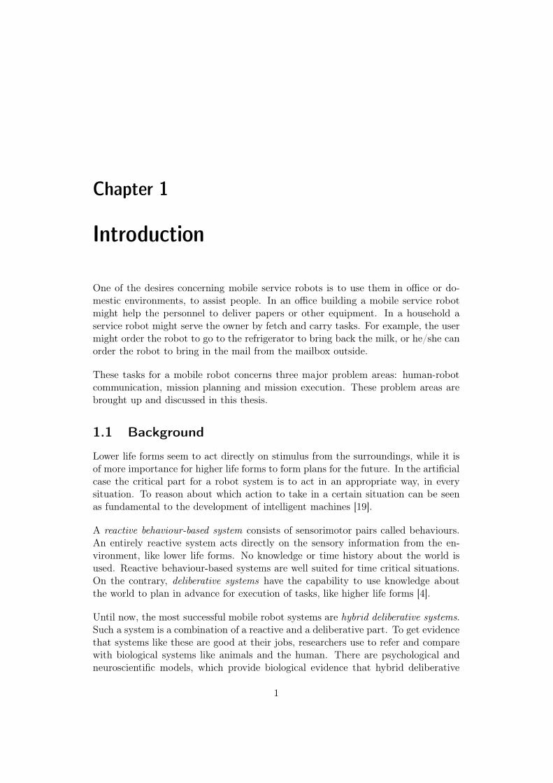
after simply referenced as ISR) developed at CAS is, as mentioned earlier, a hybriddeliberative layered architecture, see figure 1.1. The layer closest to the hardwareis called the reactive layer. The task execution layer consists of a state managerthat configures the modules of the reactive layer, to perform a certain task. Thehighest level of the software architecture consists of the mission planner and thehuman-robot interface. The human-robot interface interprets commands from theuser via keyboard, gestures or speech. The mission planner constructs a missionfrom the user commands received from the human-robot interface [11].
3

1.2.3 Approach
The deliberative layer of the ISR system misses some important capabilities suchas: the capability to enter a dialogue with the user, carry out error handling offailed missions and lack of scalability, i.e. possibility to extend the system with newfunctionality.
The aim of this master’s project is to develop a new mission planner capable tointerpret user commands in a language more similar to natural language and to re-solve ambiguous user commands, perform on-line navigation planning and executionerror handling of closed doors.
Throughout the development work of the system the aspect of scalability shall bekept in mind.
1.3 Outline
This thesis consists of 5 chapters and a number of appendices. Chapter 2 presentsprevious work done in the areas of human-robot interfacing and mission planningand methods for mission execution. The last sections related to the different prob-lem areas describe my design and solution to the problem. Chapter 3 brings upmore design details and discusses the way of implementation. Chapter 4 presentsevaluations of the different parts including working functionality, discussions aboutincapabilities and performance. Chapter 5 gives conclusions of the work done and anumber of suggestions to future improvements are mentioned.
4

Chapter 2
System design
This section presents some previous work done in the areas of human-robot dialogueand navigational mission planning. The previous work shows what is possible todo and what has been done. The mission execution problem is also of concern, butfocuses on error handling.
The user of a service robot must be able to communicate with the system in someway. For that a human-robot interface is needed to translate the user directivesinto, for the robot, executable commands. In section 2.1 are three case studies ofthe robot systems Coyote, CERO and BIRON brought up, to exemplify solutionsand methods to a human-robot dialogue system.
Section 2.2 gives a brief introduction to planning in general, concerning differentproblem formalisms, the actual nature of planning problems and hierarchical repres-entations. The general mission planners STRIPS and ABSTRIPS are brought up,which have been used a lot in practice.
The primary problem for a mobile service robot is to navigate. For that a naviga-tion planner is needed, that operates on an internal map model of the environment.There are different ways of navigation planning and therefore the specifications forthe map model are of importance. The choice of map model is discussed in section2.3. The section is first introduced with a presentation of Router’s hierarchical mapmodel.
Also in section 2.4 a couple of case studies are presented, concerning the navigationsystems of the robots Xavier and Router. The navigation system of Xavier givesan example of a complex system, which is based on probabilistic models. The sub-section about the Router system describes an application of hierarchical navigationplanning, using a multi-strategy-strategy.
The last section (section 2.5) discusses mission execution, with primary attention toerror handling of failed execution of missions.
5

The last parts of each section, named “Chosen method/model”, describes my designand solution to each of the problems.
2.1 Semantic language interpreter
Spoken language is by the far the most common mechanism for human-human inter-action and for task specification. One might expect that there is a natural affinityto use similar mechanisms for communicating with robots. In a survey related tothe robot CERO people were asked about their preferred mode of interaction for aservice robot. The results indicate that 82% would prefer to use spoken language forhuman-robot interaction, which clearly confirms the hypothesis. Other conceivableways of human-robot communication are by touch screens, gestures or by commandlanguage [14].
The results from the CERO survey show that it is desirable to be able to give com-mands to the robot system in the same way as people give orders to each other. Forthat, natural language (English) needs to be mapped to, for the robot, executablecommands. This mapping can be done in more or less sophisticated ways, fromsimple conjunctions of words to a full semantic analysis of sentences.
2.1.1 Existing methods
This section begins with some general information about natural command lan-guages, followed by previous work done in the area. The dialogue systems of threeworking robot systems, Coyote, CERO and BIRON are brought up. Each one of thepresented systems has some differential properties and presents different solutionsto human-robot dialogue problems.
Command sentences
Consider a sentence in which a human gives an order to a mobile robot to performan action. In a sentence like this a set of word components must be considered whenmapping natural language to an executable command [20].
The verbs in English language can be classified into four classes: motion, possession,vision and communication. In our case the motion verbs are of primary interest [20].
Considering the verb GO, a destination argument is needed. The destination canbe a more or less complicated description of the target position, such as an aliasor coordinates, spatial relations to another position or object or a description of atrajectory [20].
A natural language sentence can be divided into several components. The interest-ing components are:
6

VERB + DESTINATION + DIRECTION + SPEED
where all words in the different components are stored in a lexicon.
Prepositions in English language are important elements in expressions about posi-tions and paths. The number of prepositions in English are just a few if comparedto the names of all objects in the world, which make prepositions well suited forrobot commands. In English, there are two interesting types of prepositions: thefirst to describe a spatial relationship between objects (examples: behind, in frontof, beside) and the second to describe a trajectory, which is often a direction. Inthe spatial case the meaning of a preposition will not always be the same. The realmeaning is interpreted from the context where the preposition is being used, whichmakes the interpretation task of spatial prepositions complex [20].
An example of a plausible command sentence in English might be:
“Go to the table in the kitchen on floor three.”
This sentence contains a verb (go), a destination (the table) and a set of destinationrelations to other objects (in the kitchen and on floor three). This command sentencesupplies with no information about direction or speed, which may be unnecessaryto complete execution of the command.
The robot system Coyote
An existing system, Coyote, is developed with a key research goal to make naturalhuman-robot interaction advantageous. Coyote is equipped with a multimodal in-terface, including a speech interface. For the rest of this section, let us focus on itssemantic speech interpretation system only, which uses a speech recognition modulethat translates spoken sentences into text.
The text received from the speech recognition module is analysed by a natural lan-guage interpreter (Nautilus, [15]), which produces a semantic representation of thesentence. The semantic representation is similar to propositional logic and is usedto build an, for the robot, executable command [5].
Propositional logic can be used to deal with propositional formulas (sentences), asin our case. Propositional logic is also a useful tool to perform reasoning in artificialintelligence systems and in storing of knowledge [3].
In a command sentence, there is a distinction between locational and spatial rela-tions. A locational relation has coordinates related to some origin in the room or inthe world, while a spatial relation is the proximity to an object or the robot itself.Spatial prepositions are used to describe spatial relations. The spatial relation com-ponent is important to enable natural human-robot dialogs [5].
7

When the user has given a command to the robot, a verification of the commandmust be done to ensure that the command is valid and executable. For that thedialog system uses an appropriateness filter. This filter acts like a checker and canreturn error messages to the user or initiate a dialog with the user by asking a ques-tion for clarification of the recently given command [5].
Coyote performs a full semantic analysis of the command sentences, by using a lan-guage interpreter (Nautilus). Nautilus produces a representation of propositionallogic to store the semantics of a command sentence stated by the user.
When a semantic representation has been produced it needs to be validated as a cor-rect and executable command. This is done by an appropriateness filter.
Using the Nautilus interpreter, both locational and spatial relations can be used topoint out a certain target.
The robot system CERO
The spoken language interface has been developed with an iterative user-centeredwork model. When an issue was revealed in simulations and in reality, more func-tionality was implemented to make the dialogue system of CERO more complex [14].
The CERO system is equipped with a task-oriented dialogue system, which meansthat the system is primarily directed by the task given by the user. The system alsoperforms grounding, which is a way of ensuring that common knowledge is attained.With common knowledge assurance it is easier to achieve successful dialogues. Thegrounding in the CERO system is mainly done by giving feedback back to the user,about what he/she gave as spoken input to the system. Also confirmations fromthe user are requested by the system, to ensure that the system has interpreted thecommand correctly [14].
A command given by the user has to be approved before it is sent to the missionplanner. A consistency check (appropriateness filter, Coyote) is therefor done. If thecommand is not fully specified, the user is queried about the missing or unspecificdetails [14].
The CERO system is task-oriented, which implies that the behaviour of the robotis mainly controlled by the command task stated by the user. There is no complexlanguage interpretation done in the human-robot dialogue.
To inform the user about how the robot system interpreted his/her command feedbackis given back to the user. CERO may also request confirmations from the user.
8

The robot system BIRON
One of the aims of the BIRON system was to contribute to intuitive and naturalhuman-robot interaction. For those purposes a multi-modal dialogue manager anda multi-modal attention system were developed [9].
It is proven that speech is the most important way of communication. For a humanto easily engage in an interaction with a robot, user studies have shown that it isimportant that the robot moves its attention to the person who is currently speaking.This makes the robot system to be perceived, by the user, more human-like [9].
The attention system has to keep track of all people in the vicinity of the robot. Thisis to be able to evaluate the relevance of each one of the people, and to recognisewhen a person starts to talk to the robot. If a person talks the attention systemhas to determine if the person is addressing the robot. If a person is addressingthe robot the attention system switches its attention to that person by turning its“head” (camera and far-field stereo microphones) to the talking user. Only whenthe system has selected a user as the one addressing the robot speech interpretationtakes place [9].
The dialogue manager of BIRON performs command validation before a commandis executed. It also has capabilities to resolve ambiguities by asking the user forclarifications. If a user command is missing some information the dialogue managermay use information from the scene (the near surroundings of the robot) to completethe command [9].
BIRON is equipped with an attention system to make human-robot dialogues morehuman-like. The attention system also selects a user and focuses its attention tolisten for commands from that particular user.
Command validation is carried out (as for Coyote and CERO), before execution.BIRON may query the user for specification of ambiguous commands. BIRON mayalso use information from the scene to complete a command sentence.
2.1.2 Chosen method
In section 2.1.1 three successful solutions of dialog systems were presented. The abil-ity to perform basic dialogues with the user is one of the main goals of this thesis.When compared to the previous command system of ISR, some improvements havebeen made. The previous system was unable to carry out any form of error handlingdialogue. The dialogue capability has been developed in the new system, which willbe described in this section. First the design of the dialogue system is described in-cluding command sentence syntax and data structures, followed by a description ofthe major algorithm of the dialogue system. An example of a human-robot dialogueis displayed in appendix A.
9

There are three different kinds of semantic analysis. The first is the one of the ISRsystem, which is strictly rule based, working completely with predefined aliases. Thesecond is a system that carries out a full semantic analysis (Nautilus). The thirdis somewhere in between, which performs a partial semantic analysis, focusing on asmaller set of particular types of words.
To be able to handle any kind of human-robot dialogues, for correction of ambigu-ities, an appropriateness filter is needed. A filter like that can be designed with anarbitrary level of complexity. To make a complete semantic analysis of user com-mands, a large complex system is needed, e.g. Nautilus[15] – used in the Coyotesystem. Instead of a complex solution like that I chose a solution more suitable for amaster’s project, a solution that checks the target of a command sentence. A moreversatile way of expressing the target is needed to make it possible to complete badlyspecified targets. To make it possible for a user to state a target in a more versatileway, each target needs a set or relations defined to other items in the world. Theuser can then select a certain target using the related items instead. For determ-ination of the type of relation, prepositions need to be evaluated. To decrease thedevelopment effort and due to the fact that the interpretation of spatial relations isconsidered to be complex, evaluation of prepositions have been completely omitted.
The previous dialogue system of ISR was typically task-oriented – one unique com-mand for each action. A task-oriented system with the capability of checking forambiguities can easily be directed by a language similar to English. With this inmind I decided that these improvements, compared to the ISR system, would begood enough.
The tests of the human-robot dialogue system, were only supposed to be done bykeyboard input, using no voice recognition or vision systems. Therefore, and due tothe lesser focus devoted to the human-robot dialogue problem no development of anattention system, like the one used in the BIRON system, has been considered.
To make user command sentences more concise and natural, information from theenvironment in the vicinity of the robot can be used to complete ambiguous com-mands.
Design
To decrease the complexity of the semantic interpretation the components of a com-mand sentences have been limited to three components: action, target and targetspecifications. This puts on significant limits to the grammatics of the given com-mands, but many commands can still be fairly similar to human language, suchas English, and is a good trade-off with respect to less design and implementationefforts.
VERB + TARGET + TARGET SPECIFICATIONS, ...
10
The different verbs are stored in a list to make it possible to approve a given verbas valid. Each one of the remaining sentence components target and target specifi-cations resolves to a set of words. The target component resolves to a set of targetcandidates, while each one of the target specifications resolves to a set of specifica-tions for the target. As done in Coyote and CERO, an appropriateness filter is used.The filter checks and evaluates the target and its target specifications. The check isdone by a trace algorithm, in which one of the target candidates is picked out as thewanted target.
Example:GO to the TABLE in the KITCHEN on FLOOR THREE.Where, GO is the verb, TABLE is the target and KITCHEN and FLOOR THREEare target specifications. Words like prepositions and determinative pronouns areignored by the interpreter.
A hierarchical lexicon is used to recognise and store different types of words. Thewords are grouped into different sets and subsets. These entities are explained belowin BNF syntax [17]:
<word> ::= <unique noun term> <association>*<group> ::= <unique group type name> <group>+ <word>+<association> ::= <word1> ”—” <word2>
The words are nouns that exist in the world as objects. The groups are used togroup words and sub-groups of the same type of words, e.g. a type of objects in theworld. The associations are used by the trace algorithm, which searches throughthe lexicon to find an unique target that matches the target specifications.
Example:<word> ::= dinner-table kitchen—dinner-table<word> ::= sofa-table living-room—sofa-table<word> ::= kitchen kitchen—dinner-table<word> ::= living-room living-room—sofa-table
<group> ::= object table, room <group> ::= room kitchen, living-room <group> ::= table dinner-table, sofa-table
<association> ::= kitchen—dinner-table<association> ::= living-room—sofa-table
The hierarchical structure with groups and subgroups makes it possible to select,recursively, a set of words by addressing a name of the group. In the example above,if the group alias “table” is given as target, both the dinner-table and the sofa-tablewill be selected as candidates for the real target. The choice of target specifications
11

decides which one of the target candidates that will be selected as the desired target.
The ability to state target specifications to a target makes it possible to point out acertain target in several ways, not only by predefined aliases mapped to targets inthe world. If the user knows information such as surroundings, belongings and/or alocation of a target he or she can state these extra facts as target specifications andin conjunction address the target more generally by the type of the target and thetarget specifications. Spatial relations between objects cannot be represented in thelexicon, just the fact that objects are related somehow.
When the target candidates are traced three different results can be achieved:
• no candidate is validated
• exactly one candidate is validated
• more than one candidate is validated
The successful case is when exactly one candidate has been picked out. The othertwo cases can be used to initiate a human-robot dialogue.
Words in the lexicon, which represent objects in the world, may be linked to eachother by associations, to represent a belonging or proximity to each other. For ex-ample, a table in a room, where the table should be associated to the room and theroom should be associated to the table. The trace algorithm follows these links,beginning at a target candidate. Each component (target and target specifications)of the command sentence, resolves to a set of words. The set of words, resolvedfrom the target component, contains the target candidates. The sets of words, re-solved from the target specifications, contain words that may be associated to thetarget candidate, directly or indirectly through other words resolved from the targetspecifications. When an associated word is found in a set, a TRUE sign is raisedfor that particular set. When all target specification sets have the value TRUE theconjunction of these boolean values indicates TRUE as well, i.e. a target candidatehas been validated. This can be seen as a spanning tree problem, in which each oneof the arguments of the command sentence represents a node within the spanningtree.
The trace algorithm is run once for each candidate. The successful result is achievedwhen exactly one of the runs gives a conjunction of value TRUE and the other runsgive FALSE, i.e. exactly one target candidate has been validated and is supposedto be the correct one, the one to be selected as the desired target.
The trace algorithm traceSpecs in table 2.1 is a recursive function that takes twoarguments; Argument 1 (target) is in the first call a target candidate that is tobe checked if it might be the desired target. Argument 2 (specSets) is a vector ofsets, where each one of the sets contains the words that are derived from its cor-responding target specification. Row (2) checks if target is a member of any of the
12

traceSpecs(target, specSets)
(1) result1 <- init boolean result vector with FALSE elements andwith size(specSets)
(2) for cnt=1 to size(specSets)(3) aSet <- specSets[cnt]
(4) if target is a member of aSet(5) result1[cnt] <- TRUE(6) break
(7) remove target from every set in specSets(8) associations <- target.get-specs()(9) cross <- getCrossSection(associations, specSets)
(10) for every element aSpec of cross(11) if aSpec is a candidate
# Avoid recursive calls to candidates(12) remove aSpec from every set in specSets
else# Recursive call and boolean OR of result-vectors.
(13) result2 <- traceSpecs(aSpec, specSets)(14) result1 <- result1 OR result2
(15) return result1
Table 2.1. Target specification trace algorithm
specification sets. At the first hit a TRUE flag is raised (row 5) for the set in whichthe hit occurred. When a target is found in any of the sets, it is removed from allsets (row 7), to avoid infinite recursive calls. On row (8) all associated words fromtarget are derived. These associations are cross-sectioned (row 9) by the union ofall specification sets:
associations ∩ specSets = associations ∩ (specSet1 ∪ specSet2 ∪ ... ∪ specSetN)
Row (11) checks if aSpec is a target candidate, and if so removes it from the spe-cification sets. The target candidates should only be visited in the first call totraceSpecs. If target is not a candidate a recursive call to traceSpecs is made onrow (13). Recursive calls are made for each one of the cross-sectioned associationsof target. The boolean result vector from the recursive call is OR:ed (on row 14)with the local result vector.
13

The terminating criteria of recursive calls are when cross is empty, which is whenthere are no more matching words in the target specification sets.
The two cases, when none or more than two target candidates have been traced, areused to initialise human-robot dialogue. The two cases occur when badly specifiedcommands have been given by the user. Either the command is specified incorrectlyor unspecifically, which means that either is a non-matching target specificationgiven or too few target specifications given, respectively. A question from the sys-tem to the user, similar to the grounding within the CERO system (section 2.1.1),tries to complete a command. In its simplest form the system asks for new targetspecifications, either less specific or more specific, depending on the resulting case.The questions asked by the system can be customised to fit the command verb inits context.
In section 2.1 the human-robot dialogue problem was presented, followed by my solu-tion to the problem. The robots Coyote, CERO and BIRON are equipped with differ-ent kinds of human-robot interaction systems. Coyote has an advanced system thatcarries out a complete semantic analysis of command sentences spoken in English.On the contrary, CERO is equipped with a system that is task oriented and useshuman-robot dialogue, primarily to confirm commands. BIRON uses an advancedsystem attention to the current user.
A lexicon was designed, that is capable of grouping words in a hierarchical manner.This enables command sentences to target different objects in the environment in amore versatile way using a command language more similar to English. When an in-correct command has been encountered the system enters a dialogue with the user, totry to correct the command. Targets stated in the commands may be specified eitherunspecifically or incorrectly, without any matching targets in the environment.
Read more about the implementation details and the evaluation of the language in-terpreter system in chapter 3 and 4, respectively.
14

2.2 Mission planning in general
When a robot system is ordered, by a user, to carry out a mission the robot mustfirst generate a plan for the mission, before any execution can start. This plangeneration is done by a mission planner system. A plan is generally made up of asequence of actions, where each action changes the state of the world. An actionis an event that is performed intentionally by some agent in the world. The worldin planning systems uses to be thought of a state-space of infinite (or finite) states.The state of the world can be thought of as a snapshot of the world at any instantof time [19].
A planning system needs to posses all necessary information about the problemdomain (i.e. the environment). All these facts must be represented in some way.For that, different logical formalisms have been used to describe world entities likeproperties of objects, states of the world and events. One of the most general andformal is the classical situation calculus approach.
Here follows a brief description and a simple illustrating example of situation cal-culus, proposed by McCarthy & Hayes 1969 [12]. First, let us introduce the syntaxof the situation calculus formalism used to denote events and propositions. Alsoa few important predicates are presented, used to assert that a proposition is trueand denote the consequence is of a certain event. After that are a few examplespresented in table 2.2.
An event denotes as eventName(x, y, ...) where arbitrary many arguments x, y, ...are entries primarily involved by the event. Propositions about different situationsare denoted like statement(p, q, ...) where a relation between p and q is designated.Also here may arbitrary many arguments be related.
holds(f, s) is a predicate used to denote that f is true in state s. The last predicate,brought up here, is t = result(e, s) which concerns state transitions. If the event eis performed in state s a state transition occurs from state s to state t.
Type Example DescriptionTerms:Event puton(A,B) block A is put on top of block BProposition on(A,B) block A is on top of block BPredicates:Holds holds(on(A,B)) is true if block A is on top of block BResult result(puton(A,B), s) denotes the resulting state if puton(A,B)
is performed in state s
Table 2.2. Examples of terms and predicates of situation calculus [19]
15

Situation calculus use to be completed with the regular logical connectives. Here isan example of placing block A on top of block B:
∀s holds(clear(A), s) ∧ holds(clear(B), s) ⊃⊃ holds(on(A,B), result(puton(A,B), s))
(2.1)
This means, if block A and B are clear, then when puton(A,B) has been per-formed in state s, block A will be on top of block B in the state denoted byresult(puton(A,B), s).
There is one problem with the this approach called the frame problem. Consider thatblock B is red before A is put on top of B, there will be no way to conclude, fromaxiom 2.1 alone, that B would still be red after the movement of A. This means thatfor all unaffected properties extra axioms must be formed to describe that certainproperties are not affected [19].
One way to avoid the frame problem is to use an alternative representation to situ-ation calculus. The most known one is STRIPS and was developed to go aroundthe computational problems of situation calculus. In STRIPS a state is representedby a state description, composed of conjunctions of logical formulas. Actions (orevents) are represented by operators, where each operator consists of preconditions,an add list and a delete list. The preconditions of an operator are a set of logicalformulas that decide when the operator is applicable. An applicable operator canbe performed by changing the state according to the operator’s add and delete lists.The logical formulas in the operator’s add list are known to be true and are addedto the state description, while the logical formulas in the delete list may not be true,after the operator has been performed, and must be removed from the state descrip-tion, if they are present. In this way a state transition is carried out by performingan operator. This scheme is known as the STRIPS rule [19].
Example of a STRIPS operator:
State descriptor: loc(A, 0), clear(A), red(A)
OperatorPrecondition: loc(A, 0) ∧ clear(A)Add list: loc(A, 1)Delete list: loc(A, 0)
Consider the situation above, where the current state is described and an operatoris defined, the precondition of the operator is satisfied (true) according to the statedescriptor. The block A is in position 0 and A is clear. The property red is notconsidered by the operator. With the precondition satisfied it is possible to selectthe operator for execution, which gives the new state:
State descriptor: loc(A, 1, clear(A), red(A)
16

A more detailed description of STRIPS is not given here, but important to knowis that STRIPS avoids the specification of frame axioms to make it computationalless demanding in implementations of planner systems. If compared, STRIPS is farfrom as expressive as situation calculus. Modifications have been made to STRIPSto improve it in different ways, but with other limitations as consequences [19].
2.2.1 Planning – search
A mission to be planned has one or multiple goals that must be achieved for themission to be considered as accomplished. In every situation an agent has to performone of all possible actions, which will lead towards a goal of the mission. This canbe seen as a pure search problem: “Find some or all possible orderings of the agent’sactions that would result in achieving the specified goal, given the constraints of theworld in which the agent is embedded.” This straightforward search problem is NP-hard, where the number of possible action orderings is the factorial of the numberof the agent’s actions. Two major views of search techniques exist: one where thesearch is done in a space of world states and the transitions between states is doneby performing an action. The other view is a search in a space of partial plans.The view of partial plans is more general where the state space representation canbe seen as a special case of partial plans, which might be extented with primitiveactions [19].
The search for a solution plan can be seen as plan specialisations, where different planspecialisation operators are applied. The specialisations continue until a plan specificenough is found that can be classified as a solution plan. An alternative to planspecialisation is plan modification, where the search starts with an approximation toa solution plan and modification operators are applied to modify the plan towards aplan that could be a solution plan. A problem with plan modification is that it canbe difficult to know if a modification changes the plan closer to a solution. In someapplications it is very effective to combine both search methods, (see The Routersystem, 2.4.2) [19].
2.2.2 Hierarchical planners
One way to improve the planning search, is to arrange the problem domain hier-archicly into different levels. In a true hierarchical planner the higher levels arehomomorphic images of the original problem, at the lowest level. This means that ifa solution exists at the lowest level there are corresponding solutions at the higherabstract levels as well, which results in preservation of the problem structure evenat the higher levels. ABSTRIPS is a planning system that has been used widely. Itmaintains homomorphism by neglecting those predicates that specify details in theplanning domain. In this way the planning search will be focused on more significantproperties in the planning domain [19].
This section has given some insight into mission planning in general and also some
17

knowledge of a few of the first widely used planning systems, like STRIPS. When theproblem domain is known, which is the most usual case, it is often very advantageousto use a specialised planning system, with consequences like more intuitive domainrepresentation and computational more efficient planning.
Hierarchical methods may be feasible to make planning tasks even more efficient. Thegeneral hierarchical planning system ABSTRIPS was mentioned, which has been useda lot in practice. It preserves homomorphism by neglecting details at the higher levelsof abstraction.
More about planning can be read in section 2.4, which focuses on specialised planningsystems for robot navigation.
18
2.3 Map representation
Navigation must be carried out on an internal map model, either a previously definedstatic model or a dynamic model generated at runtime. The structure of an internalmap representation is of importance with respect to in which way and how efficientlynavigation planning is performed. Depending on the type of navigation planning themap representation should be designed to fit the desired conditions.
A hierarchical map representation has a couple of advantages compared to a non-hierarchical. For example, to perform on-line planning a hierarchical map repres-entation might provide with natural delimiters for each partial navigation search.
This section presents a hierarchical map representation used by the Router robotsystem. The last part of this section describes my design of a map representation.
2.3.1 Router’s hierarchical map model
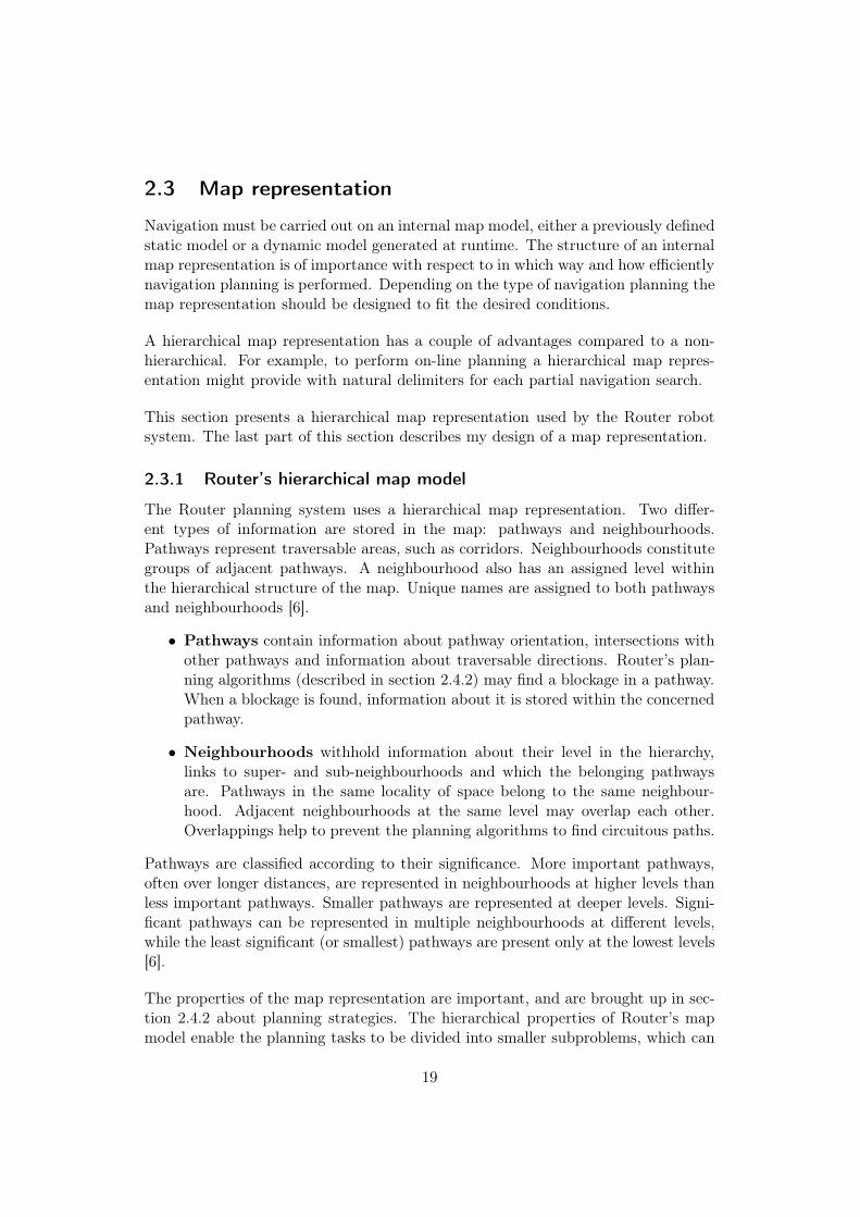
The Router planning system uses a hierarchical map representation. Two differ-ent types of information are stored in the map: pathways and neighbourhoods.Pathways represent traversable areas, such as corridors. Neighbourhoods constitutegroups of adjacent pathways. A neighbourhood also has an assigned level withinthe hierarchical structure of the map. Unique names are assigned to both pathwaysand neighbourhoods [6].
• Pathways contain information about pathway orientation, intersections withother pathways and information about traversable directions. Router’s plan-ning algorithms (described in section 2.4.2) may find a blockage in a pathway.When a blockage is found, information about it is stored within the concernedpathway.
• Neighbourhoods withhold information about their level in the hierarchy,links to super- and sub-neighbourhoods and which the belonging pathwaysare. Pathways in the same locality of space belong to the same neighbour-hood. Adjacent neighbourhoods at the same level may overlap each other.Overlappings help to prevent the planning algorithms to find circuitous paths.
Pathways are classified according to their significance. More important pathways,often over longer distances, are represented in neighbourhoods at higher levels thanless important pathways. Smaller pathways are represented at deeper levels. Signi-ficant pathways can be represented in multiple neighbourhoods at different levels,while the least significant (or smallest) pathways are present only at the lowest levels[6].
The properties of the map representation are important, and are brought up in sec-tion 2.4.2 about planning strategies. The hierarchical properties of Router’s mapmodel enable the planning tasks to be divided into smaller subproblems, which can
19
be solved independently. Powerful recursive algorithms can operate on the treestructure that the neighbourhoods build up [6].
2.3.2 Chosen map model
The previous map representation of the ISR planner system was built up by atopological navigation graph, where each node in the graph represents a room. Insideeach room could a set of navigation points be defined.
The improvements made to the new map representation are the hierarchical structureand the capability to define navigation graphs even inside rooms. Two rooms withseveral exits between each other could not be handled by the previous system (ISR).By introducing navigation graphs also inside rooms that problem was easily solved.The achievement of a general design of a map representation was one of the aims inthe development.
When planning long routes it is not very profitable to make too detailed plans allthe way from the start position to the goal position at once. The environmentmay have changed or is changing while the robot is moving, which makes replanningnecessary. While replanning, the current plan has to be discarded and a new detailedplan must be resolved. To avoid this inefficient way of replanning, a hierarchical maprepresentation is used, similar to the one used by the Router system, (see section2.3.1). The hierarchical property implies reasonable delimitations for each partialplan.
Design
In contrast to Router’s map representation, the elements in the map of the new maprepresentation are just leaf nodes and nodes, no large entities like paths or pathwaysare used. The nodes are arranged in a hierarchical manner with arbitrary manylevels, depending on the characteristics of the environment.
• Each node has an unique alias, a supernode, an alignment and position co-ordinates relative to its supernode and a set of children (leaf nodes and nodes).
• Each leaf node has an unique alias, position coordinates and a supernode.
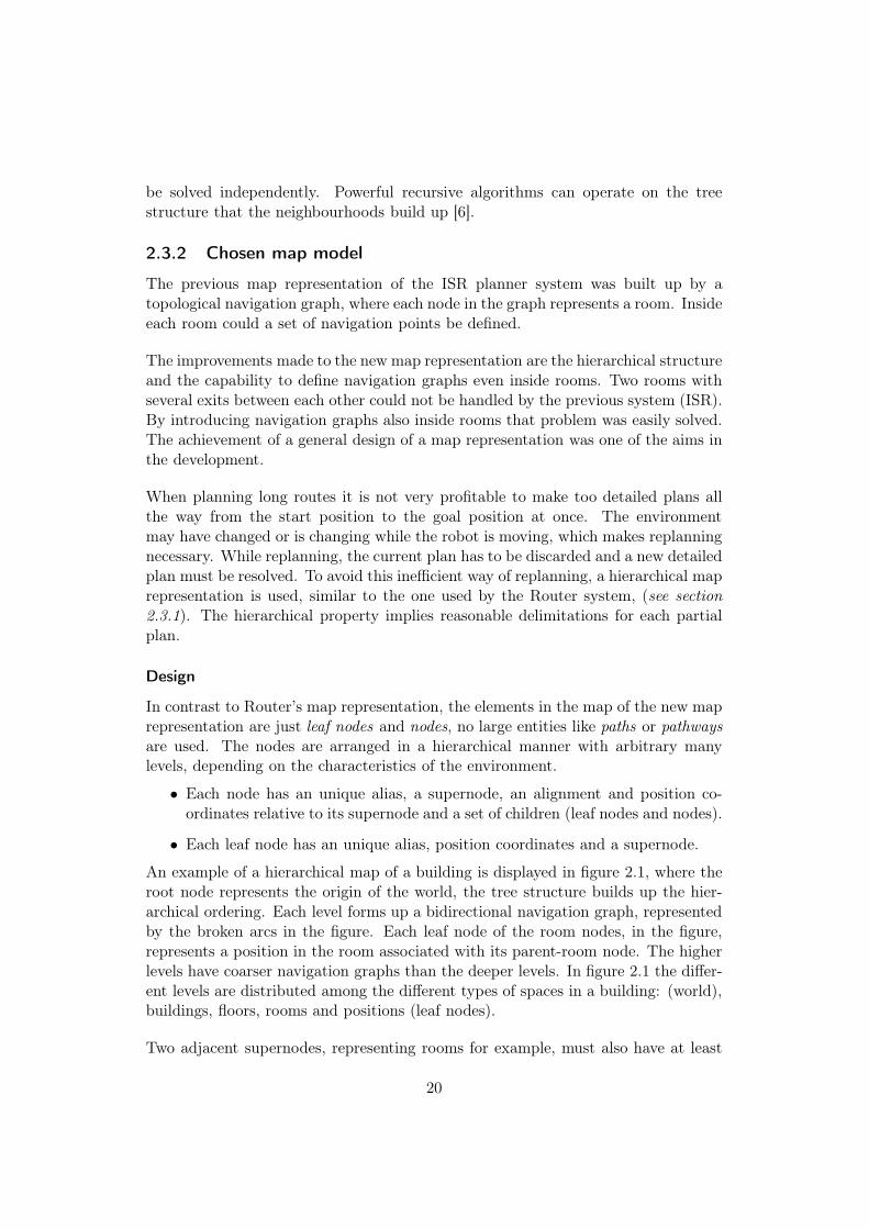
An example of a hierarchical map of a building is displayed in figure 2.1, where theroot node represents the origin of the world, the tree structure builds up the hier-archical ordering. Each level forms up a bidirectional navigation graph, representedby the broken arcs in the figure. Each leaf node of the room nodes, in the figure,represents a position in the room associated with its parent-room node. The higherlevels have coarser navigation graphs than the deeper levels. In figure 2.1 the differ-ent levels are distributed among the different types of spaces in a building: (world),buildings, floors, rooms and positions (leaf nodes).
Two adjacent supernodes, representing rooms for example, must also have at least
20

World
Buildings
Floors
A room nodeis a leaf
Rooms
Leaf nodes
Figure 2.1. Example of a hierarchical map representation of a building
one pair of adjacent subnodes. This condition must be met recursively all the waydown to at least one pair of leaf nodes. A real path, that is to be followed by therobot, is entirely made up of leaf nodes. This property is defined as: higher levelsare homomorphic images of the deeper levels, see section 2.2 Hierarchical planners.
In section 2.3.1 the interesting map representation of the Router system was presen-ted, which is a hierarchical map representation built-up of the entities pathways andneighbourhoods.
At last my design of a hierarchical map model was presented, which has a more gen-eral structure than the one of Router.
The design of a navigation search method, for the map representation described here,is described in section 2.4.4.
21

2.4 Navigation planning
This section begins with presentations of two navigation systems used in differentresearch projects. The two navigation systems described were implemented on therobot systems Xavier and Router respectively. These systems are brought up toillustrate two significantly different ways of navigation planning. The navigationplanner of Xavier is very stable, due to the fact that it maintains a probabilitydistribution over its position. The Router system is equipped with an hierarchicalmulti strategy strategy navigation planner, which uses different methods dependingon previous knowledge.
In subsection 2.4.3 are three different graph search algorithms presented, frequentlyused in navigation planning applications. The algorithms presented here are Dijk-stra’s algorithm, the A*-algorithm and a brief explanation of the Incremental A*-algorithm.
The last subsection describes my solution to the navigation planning problem. Ahierarchical search algorithm has been designed, which operates on the map repres-entation described in section 2.3.2.
2.4.1 The robot system Xavier
The most widely used traditional navigation methods are metric based navigationand landmark based navigation. The metric basted navigation uses metric maps todirect the robot by moving a certain distance in one direction, after which the robotmoves a distance in another direction, and so forth until it has reached the goalposition. This works entierly by information about the motion of the robot usingwheel encoders. This type of measurement is known as odometry [8].
The landmark based navigation uses a topological map in conjunction with sensedlandmark features in the environment. The topological map represents positions inthe environment together with information about the landmarks that can be sensedat each position. The navigation is performed by moving using the topologic mapuntil a landmark can be sensed (e.g. a door opening or a corridor junction, sensedusing sonars), after which the robot may move to the next landmark or stop [8].
When mobile robots traverse long corridors in office environments for long time theytend to get lost. This happens to robot systems that rely on either odometry orlandmarks in the environment. Odometry encoders become inaccurate over timedue to the wheels slip against the floor, or landmarks can easily be missed by therobot’s sensors. Even the most advanced systems of these tend to get lost and hasto relocate itself [8].
If multiple navigation methods could be used together a more robust system mightbe achieved. Instead of just relying on one single type of measurement several sources
22

of information about the current situation would be more reliable. To get this work-ing well the uncertainties of each information source is taken into account. One wayto represent this information is with partially observable Markov decision processmodels (POMDP). A navigation system based on POMDPs was implemented intothe robot system Xavier to perform navigation tasks. It worked with the differentuncertainties in actuation, sensing and sensor data interpretation, uncertainty in theposition of the robot and about different features in the environment (e.g. people,other blockages or doors) [8].
When a robot navigation system, based purely on odometry or landmarks, gets lostit easily becomes completely lost and has to relocate itself with a relocation pro-cedure, which is a very time consuming task. As a navigation system based onPOMDPs uses all its sensor data, including odometry encoders and landmarks, tomaintain a probability distribution of the robot’s position it will never be completelylost. On the contrary, a system based on POMDPs usually does not know the exactposition of the robot. Experiments done have shown that Xavier worked very welland did not get lost. In an experiment the system was required to navigate over 60kilometers for a long period of time [8].
For insights into position determination and navigation using POMDP’s, see ap-pendix B.
Mobile robot systems, using metric based as well as landmark based navigation tech-niques, tend to get lost due to the fact that actuation and sensor information areafflicted with uncertainties. Using multiple information sources for actuation andposition measuring and also taking the uncertainties into account a more reliablenavigation system can be obtained.
2.4.2 The path planner of the Router system
A mobile service robot may operate in a limited area like a building, a domesticsetting or an office. Previously planned navigation missions are likely to be repeatedagain in the future. A previously planned mission can be used either partially orin its entirety. The usage of previously stored navigation plans might improve theefficiency of navigation search. A navigation system that could use informationfrom previously planned missions was developed on the robot system Router, usingmultiple strategies for how new navigation plans were generated.
Router was equipped with a multi-strategy-strategy path planner. To solve pathplanning problems efficiently, it combines two methods (strategies): a model-basedand a case-based method. The model-based method analyses a spatial model ofthe world and the case-based method uses stored results from previous planningsessions. Both strategies can be used to complete each other in the same planningsession. See the arrangement of the different components of the system in figure 2.2[6].
23

Model-based planning
The model-based path planning method carries out an analysis of the hierarchicalspatial model of the world. The hierarchical property of the world model providesa decomposition of the the planning task into subproblems, which can be solvedrecursively. Two tasks are carried out by the model-based method:
• Neighbourhood finding
• Path finding
The neighbourhood finding task identifies the neighbourhoods of the start and goalpositions. The identification starts at the highest level in the neighbourhood hier-archy. The neighbourhood finding task also calculates the direction from the startposition to the goal position [6].
The path finding task takes as input the start and goal positions and the results fromthe neighbourhood finding task to derive a sequence of pathways from start to goal.By first searching the higher level neighbourhoods and then recursively searchingthe lower levels, the same search procedure can be used at all levels [6].
The results from the model-based method are indexed and stored in a case memory,for future use by the case-based method [6].
Case-based planning
The case-based method derives solutions by using information from previous pathplanning sessions. These planning sessions are indexed and stored in memory. Theindexing of a stored session is done with respect to the hierarchical structure of theworld model and the start and goal positions. Like the model-based method, thecase-based method also uses a set of tasks to carry out path planning. It uses fivesubtasks:
• Case retrieval
• Case adaptation
• Case storage
• Plan evaluation
• Case validation
Brief descriptions of the subtasks are given below.
The case retrieval task searches the case memory for cases that are as close as pos-sible to the current planning session. The search is done by using the neighbourhoodfinding task to match the current planning session with previously stored ones. If
24

Path-planning task
Neighbourhood finding Path finding
Model-basedmethod
Case-basedmethod
Model-basedsimulation
Casevalidation
Caseadaptation
Planevaluation
Casestorage
Caseretrieval
Figure 2.2. Task structure of the Router system [6]
an exact match is found it is used as a solution to the problem. If an exact matchcannot be found, partial matches may be used. A partial match is found if both thestart and goal positions are within the same neighbourhoods as their correspondingstart and goal positions, found in the case memory. The partially matching case isadapted to solve the current planning session [6].
The case adaptation task uses a recursive procedure to adapt a partial matchingcase to the current planning problem. The recursive procedure divides the probleminto subproblems, which are solved by the path planning method (strategy). Foreach problem two subproblems can be formulated, one at each end where the pathmay be incomplete. Due to the recursive procedure, solutions made up of multiplepartial matching cases can be achieved. If no partial match is found no solution canbe derived, the case-based method terminates and the model-based method must beinvoked to solve the planning task [6].
New results from the case-based method are also indexed and stored in the casememory.
The tasks case validation and plan evaluation depend on the model-based method.The spatial model keeps updated to changes in the world, in contrast to the casememory. It would be computational too expensive to keep the case memory up-dated. Each pathway might be represented arbitrarily many times in different cases
25

and an update would mean a modification of all involved cases in memory. Instead,simulations in the spatial model are carried out to evaluate cases and validate plansproduced by the the case-based method. These subtasks are skipped if the Routersystem runs purely in the case-based mode [6].
The case storage task stores new plans as cases in the case memory, either if themodel-based method or the case-based method has produced the plan. In the situ-ation when the case-based method comes up with a new plan, it combines severalother previously stored cases to form a new case [6].
Router has a method selector system that decides which strategy to use, given a spe-cific task. The method selector system works in general for any planning task. Thepath planning task has the model-based and the case-based methods, which havedifferent performances in different situations. Intuitively, the case-based method iscomputationally more efficient than the model-based method, thus if a matchingcase is found in memory it can be used for the mission execution directly [6].
Router can run in multistrategy mode, which means that several methods are usedto complete each other. The two methods within the planning task can be used inmultistrategy mode, consider the case adaptation task. Results from experimentsdone with Router showed that the case-based method is significantly more efficientthan the model-based. Therefore, in multistrategy mode, it is reasonable to choosethe case-based method before the model-based. Experiments also showed that themultistrategy mode is actually less efficient than the model-based method alone.In other words, it would have been advantageous to run purely the model-basedmethod if the case-based method cannot solve the task alone [6].
Router uses a multi-strategy-strategy, which means that it uses one of two differ-ent planning algorithms depending on previously stored navigation data in the casememory. The spatial hierarchical map model of the Router system provides an in-dexing scheme for the case memory. It also enables model-based case validation andplan verification of the case-based path planning.
It is possible for Router to use both planning methods in conjunction, but experimentshave showed that this is not more efficient than the model based method alone. Thefastest planning search is achieved when the entire navigation task is performed bythe case-based method.
26

2.4.3 Graph theoretic algorithms
A topologic map can be represented as a directed or bi-directed graph. In such agraph, the navigation planner oughts to find the shortest path between two arbitrarynodes. This search can be done by an exhaustive search to find the optimal solutionor, more preferably, by a heuristic method. The algorithms brought up in this sectionare Dijkstra’s algorithm, A* and Incremental A*.
Dijkstra’s algorithm
One of the most known shortest-path algorithms is Dijkstra’s algorithm. It provideswith optimal shortest-path solutions in weighted digraphs with non-negative edgeweights.
Dijkstra’s algorithm, in table 2.3, iterates through the graph G by building up asearch tree from the start node s. A subset of the nodes of the search tree belongto the shortest-path tree [2].
Consider the graph G(V,E), at each iteration the search tree is incremented with anew node from G. When a new node w is added to the search tree its data fieldsmust be updated: distance (the path length to w from s) and predecessor (the par-ent node of w in the search tree). This new node is not immediately incorporatedinto the shortest-path tree. When the successors wi to a node v has been added tothe search tree, v is added to the shortest-path tree. A node w in the search tree,but not in the shortest-path tree, that is nearest to the start node s is selected ateach iteration for expansion of its successors.
The function GetMinDist that operates on the heap reached returns the node withthe smallest distance value. If reached is empty NULL is returned. If a path has beenfound successfully the goal node g is returned from Dijkstra’s algorithm, otherwiseNULL is returned. From the goal node, it is possible to follow the nodes’ predecessorsbackwards to derive the shortest path.
Dijkstra’s algorithm can be run in O(|E|log|V |) time. GetMinDist is O(log|V |),adding nodes to reached isO(log|V |). For node v the inner for-loop isO(deg(v)log|V |)|.Per iteration, this is in average O( |2E|
|V | log(|V |)). The total work isO(|V |2|E|log(|V |)/V+|V |log|V |) = O(|E|log|V | + |V |log|V |) = O(|E|log|V |) [2].
27

Dijkstra(G,s,g)
reached <- init Heap
for each node v in Gv.pred <- nonev.dist <- M (a large value)
s.dist <- 0reached.add(s)
v <- reached.GetMinDist()while (v is not NULL AND v is not g)
for each neighbour w of v
if w is unvisitedreached.add(w)w.pred <- vw.dist <- v.dist + length(v,w)
else if w is in reached AND w.dist > (v.dist + length(v,w))w.pred <- vw.dist <- v.dist + length(v,w)
v <- reached.GetMinDist()
return v
Table 2.3. Dijkstra’s algorithm
28

A* (A-star)
There is a heuristic shortest-path algorithm called best first-search (BF-search). TheBF-search algorithm is not much used in practice, but it does form up an algorithmskeleton which is similar in all BF- strategies. The A* algorithm (A-star algorithm)is a BF- strategy, but it has some improvements if compared to BF-search. Themajor differences between different BF- strategies are in their heuristic evaluationfunctions f(n).
To estimate if a node n in graph G promises well for the next expansion the BF-search algorithm uses the heuristic evaluation function f(n). This function may becalculated with respect to the description of n, the description of the goal, informa-tion concerning how n was reached and the most important, extra knowledge aboutthe problem domain.
In navigation planning, a reasonable choice for f(n) could be the Euclidean distancefrom node n to the goal. A* (see table 2.4) uses an additive variant of this heuristicevaluation function:
f(n′) = g(n′) + h(n′) (2.2)
where n is the current node and n′ is the successors of n. g(n′) = g(n) + c(n, n′)where c(n, n′) is the cost value of the edge from n to n′. The function h(n′) is anestimate of the cost of the best path from n′ to goal, for example the Euclideandistance between n′ and the goal.
The complexity of A* can be calculated analytically on probabilistic models. Ne-cessary conditions for A* to maintain polynomial search complexity is that A* areguided by a heuristic evaluation function h(n) with logarithmic precision (logN)k,where N is the depth of the goal node in the shortest-path solution and k > 0 [13].
29

A-star(G,s,g)
init heap OPEN, CLOSEDOPEN.add(s)
while TRUEif OPEN is empty
return FALSE # no solution exists
n <- (Delete from OPEN and return the node nthat has the minimum f-value)
CLOSED.add(n)
if n is a goal node greturn n # a solution is found
else# Expand node nfor every successor n’ of n
if n’ is neither on OPEN nor CLOSEDOPEN.add(n’)n’.pred(n)calculate f(n’) = g(n’) + h(n’)
# Estimate h(n’) and calculate g(n’)# g(n’) = g(n) + c(n,n’)
else if n’ is already on OPEN or CLOSED# re-direct the predecessor pointer# of n’ to nif (g(n) + c(n,n’)) < (current g(n’))
n’.pred(n) # re-direction
if n’ is on CLOSEDMove n’ from CLOSED to OPEN
Table 2.4. The A* algorithm
30

Incremental A* - LPA*
Mobile robots that manoeuvre in dynamic environments often need to quickly replantheir missions. Planners that is capable of planning continuously, while a missionis executing, are known as On-Line planners. Incremental A* (also called LPA*- Lifelong Planning A*) is an One-Line planner which uses the A* algorithm, butalso reuses information from previous planning sessions. In this way subsequentplannings are carried out much faster.
The initial planning of a certain mission is done just like A*, but the subsequentplannings or replannings reuse the existing search tree as much as possible. For acertain goal node, the intermediate nodes to the goal are marked with the travelcost to the specific goal node. Being at any intermediate node, it is easy to greedilychoose the neighbour node with the lowest cost value.
Experiments done in an eight-connected grid-map show that LPA* is faster thanA*. In these experiments, A* made about 11 times more node expansions thanLPA*, about 5 times more node accesses and about 7 times more heap percolates(parent-child exchanges in a heap) [18].
31

2.4.4 Chosen method
In the earlier parts of section 2.4 a couple of case studies were presented, to exemplifydifferent successful navigation systems. In this subsection a hierarchical navigationplanner is described.
Navigation planning
As mentioned in section 2.3.2 the previous planning system of ISR used a topologicalmap, representing rooms as nodes in a bidirectional graph. A new map model wasdesigned, as a hierarchical representation of multiple topological navigation graphsat different levels of abstraction. To perform navigation planning using that maprepresentation a hierarchical search method is needed.
The navigation system of Xavier is very robust, which makes the development of asimilar system to seem to be a good choice. The navigation system of Xavier is notjust a route planner, but also an position tracker. To develop a position trackingsystem like the one of Xavier all available sensor data should be taken into account.Our system is equipped with wheel encoders, sonars and a laser scanner and isalready equipped with a position tracker, at the Task Execution layer (Localiser,see figure 1.1). The primary intention of this master’s thesis project was to developan improved navigation planner, but not necessarily a position tracker. From this Iconcluded that it would demand too much work to develop a system like the one ofXavier. The development of new parts both in the deliberative layer (planner) andin the reactive layer (position tracker) would most truly imply the development ofa completely new system without any usage of the ISR system. This reasoning leadto that the development of a system like the one of Xavier was entirely omited.
The Router system used a multitask navigation system, with both model based andcase based navigation methods. Router’s case based method did only perform betterthan its model based method, when it could find the entire solution path with thecase based method alone, which would demand a lot of “experience” from previousplanning sessions. To limit the implementation efforts and due to the low gain ofthe case based methods I chose to use a model based method only. With this inmind and that with the intentions to develop a navigation planner that performsplanning in an on-line manner, I chose to neglect the use of any stored “experience”from earlier planning sessions. To perform mission replanning, it is profitable if theplanning is not done from the start node to the goal node every single time. Forthat I designed the hierarchical map representation presented in section 2.1, whichis suitable for replanning, as the planning is done in several stages.
Design
In this part the level-search algorithm and the important search session variable aredescribed. Finally the graph search algorithm, used by the level-search algorithm,
32

is motivated.
The search session vector serves the same purpose as the stack of a recurs-ive algorithm. The iterative algorithm levelSearch (see table 2.4.4) traverses thehierarchical tree recursively by maintaining a tree descriptor vector (SESSION). Thetree descriptor vector describes the map structure that has been searched, but notyet traversed. The reason for using a tree description vector instead of a recursivealgorithm is due to the fact that the search is done in multiple runs. Between eachrun the current search session must be stored in some way until next run, which iswhen the robot has reached a position where further planning is needed. Thereforeis this tree descriptor vector also called the search session vector/variable.
Each derived partial path, of non-leaf nodes, at each level is added to the search ses-sion vector, until one of the terminal criterias is met (read more about the terminalcriterias in the next paragraph). Before a path of leaf nodes is returned for execution(navigation) all its supernodes, that only cover nodes within the path (that cover nonodes outside the path), are stripped off from the session vector, including all cover-ing nodes at the higher levels. The reason for removing these nodes from the sessionvector is to keep it updated according to the current state, which is to be changedwhen a path is returned for execution. The remaining nodes in the session vectordescribe, at a higher level of abstraction, the further path towards the destination.
The level-search algorithm was designed to be as general as possible, i.e. itshould treat all parts of the hierarchical map representation with as few special casesas possible. The algorithm traverses the hierarchy tree recursively in a local-branch-breadth-first-search manner. Higher levels within the local branch are searchedbefore deeper levels outside the local branch. A local branch is a subtree of thehierarchical map structure, in proximity to the current position of the robot. Allthe variables in table 2.4.4, written in capitals, are global variables stored outsidethe function levelSearch. The search function takes two nodes as arguments: astart node and a destination node (from and to ). The main loop iterates throughthe levels of the map hierarchy until any of the terminating criterias is met at row(5) or (7): no path found (row 5), a leaf start node is reached (row 7). At row(2) the global variable LVL is increased by one, after which a call to a shortest-pathalgorithm is made at row (3). The path retrieved at row (3) is stored in the globalSESSION vector at row (8), together with the number of nodes in that partial path.
The rows (9) to (15) derive the next start and goal nodes at a deeper level, to beused in the next graph search. If the first partial path in SESSION consists of onesingle node, which means that from and to have the same supernode, a destinationnode at a deeper level is derived at row (10). If a destination node at a deeper levelcannot be derived, due to less depth of the destination leaf node, a node at a higherlevel must be used instead. This node is derived from the SESSION vector at position2, where the latest stored partial path is found. At position 1 the size of the latest
33

levelSearch(from, to)
(1) while TRUE(2) LVL <- LVL + 1
(3) path <- searchGraph(from, to)
(4) if path = FALSE(5) return FALSE
(6) if (from has no subnodes)(7) break
(8) SESSION <- path.size(), path, SESSION
(9) if (the first element of SESSION = 1)(10) to <- DEST.getNodeAtLvl(LVL + 1)
(11) if (to is not a node)(12) to <- SESSION[2]
(13) else(14) to <- SESSION[3]
(15) from <- START.getNodeAtLvl(LVL + 1)
(16) stripSession()(17) return path
Table 2.5. Hierarchical navigation planner algorithm
34

partial path is stored.
Row (14) handles the case when the destination node and the start node are locatedinside different sub-trees. In this case a node at a deeper level should not be derivedfor the destination, a graph search must only be carried out locally within a super-node. This is to constrain the searches hierarchicly. The node stored at position3 in SESSION is the next adjacent node in the path at the current level. Row (15)derives a new from-node at a deeper level.
The graph search algorithm used, returns a shortest path within a supernode.An interesting graph search method is the Incremental A* algorithm. It storesshortest-path data as experience, that can be used in later runs. This data stor-age demands some administrative tasks, where each goal node might have relateddistance data concerning all other nodes. Incremental A* works well with a mapmodelled like a large single worldwide navigation graph, due to the fact that it usesstored data to make the future searches more efficient. A search method like In-cremental A* is unnecessary when a hierarchical map representation is being used.When the supernodes of a hierarchical map are distributed finely enough each searchrun complete quickly. The search time of a complete search, from the start nodeto the goal node, is spread out over several smaller searches, which prevents resultsfrom the search algorithm to be delayed. The navigation planning is done in anOn-Line manner.
Considering that, I chose A* as the graph search algorithm, see table 2.4. In naviga-tion tasks A* is well guided by its heuristic estimation function (often the Euclideandistance function) if compared to Dijkstra’s shortest-path algorithm. Two importantmodifications of A* had to be done to apply it to the hierarchical map; A selectivecondition was introduced and the terminal condition was modified. The selectivecondition had to perform a local selection, which means that no path-successorsoutside the current supernode should be included in the search. The terminal con-dition, when a goal node is found, was changed to return a solution path when anyof the supernodes of the goal node has been found.
In subsection 2.4 two existing navigation systems were presented, developed on therobot systems Xavier and Router, respectively. The Xavier system was equipped witha navigation system based on partially observable Markov decision processes, thatmakes up a very robust navigation system that never is completely lost. The Routersystem, that uses a hierarchical map model, has a multi-strategy strategy naviga-tion planner, in which multiple methods can be used in conjunction to complete eachother. The last part of section 2.4 considered the graph search algorithms A*, LPA*and Dijkstra’s algorithm, which are frequently used to solve shortest-path and navig-ation planning problems.
The last subsection presented my solution to the navigation problem, which described
35

the level-search algorithm that performs navigation planning in an on-line man-ner.
Some implementation details and further design issues are described in chapter 3.In chapter 4 some limitations and advantages are discussed.
36

2.5 Mission executer
The mission executer is the part of software that initiates execution of subtasks ofan already planned mission. The mission planner sends a sequence of subtasks tothe mission executer, which is responsible for the sequential processing of entries ina plan by modules at the lower layers of the system, i.e. the Supervisor in figure 1.1.
As the executer module is essential but not part of the major work of this master’sproject this section is brief. On the other hand the mission executer has an import-ant role in error handling. Therefore this section focuses on error handling for theexecuter system.
This section begins with some general examples of properties and capabilities suit-able for sequencing and schedule repair methods. The methods described could beapplicable to the mission executer of our robot system, to provide the system witherror handling and more sophisticated ways of mission execution.
2.5.1 Sequencing
The easiest way to execute a plan is by a simple sequence of the subtasks of a plan,i.e. execute the next subtask when the current one has finished. With this method,when a subtask terminates with an error, there is no way to determine if the nextsubtask can be executed with or without problems. The next subtask can either beexecuted without problems or else the entire mission must be aborted. The failedsubtask might have completed just partially, but far enough to make it possible forthe next subtask to be executed successfully. There is no meta-information availablethat specifies how the next subtask depends on the previous one. For example,meta-information could tell that to successfully complete step 2, step 1 must havecompleted. The safest method is therefore to tolerate no errors at all and if an erroroccurs, terminate the entire plan execution, enter some sort of safe mode and signalwith an error to the user. This execution method is known as linear sequencing andcan only perform error handling with the mark-and-rollback method. This errorhandling method simply rewinds a sequence to an earlier, previously marked, pointto repeat a part of the sequence [7].
To improve the error handling non-linear sequencing might be used. When no errorsoccur it works exactly like linear sequencing, by a sequence of subtasks. When anerror has occurred the failed subtask is responsible to generate a fail signal to thethe executer. This responsibility require cognizant failures, which means that thesubtask procedure never fails to report a failure. When a cognizant failure signalhas been sent the executer checks to see if there is a recovery procedure availablefor the failed subtask. If there is one it is executed and followed by either thepreviously failed subtask or the next subtask in the sequence, depending on thecharacteristics of the problem domain. The execution of a subtask primitive will
37

only fail completely if both the subtask primitive and the recovery procedure failsor if no recovery procedure is available [7].
2.5.2 Schedule repair
The sequencing methods of executer systems do not manipulate the superior order ofplans, i.e. only the execution order of subtasks primitives within a plan is considered.As a complement schedule repair methods can be used, to reorder plans to performa more advanced error handling. A scheduler operates in close connection to themission planner and the executer.
This part is about mission schedulers only in relation to error handling, not missionscheduling in general, which is beyond the scope of this thesis.
Some examples of error handling by a scheduler might be: exploit opportunities,interleave delivery jobs and initiate replanning of interrupted plans. Some of thesecapabilities are briefly described in the following paragraphs.
To exploit opportunities means that the scheduler observes properties of theenvironment that might be of importance for the currently executing mission or amission that previously was interrupted, due to the fact that it was impossible tofinish. For example, while a mission is executing a property is noticed as changed,i.e. a door has been opened, which might benefit the mission. This opportunity maybe evaluated by replanning and if it is favourable the new alternative plan can beused [16].
Also, consider the case in which a plan is being executed and a property has beenobserved as changed, favouring an interrupted plan, the interrupted plan mightbe rescheduled for execution directly, by postponing the currently executing plan.For example, a previously closed door may be observed as open, that initiates res-cheduling of an interrupted plan which previously tried to access the closed room.Exploitation of opportunities is often used to interleave delivery jobs [16].
Replanning of an interrupted plan , that is to be rescheduled, is in the mostcases necessary, due to the fact that the physical state (e.g. location or angle) ofthe robot has truly changed since the plan was interrupted. The rescheduler mustbe able both to initiate the mission planner and reorder different missions in theexecution sequence [16].
2.5.3 Chosen method
An execution module is required to initiate the subtasks at the right time and in theright order. My intentions were to achieve a simple and general executer system.The demands to the executer system were that it shall have the capability to workthrough a queue of subtasks, wait for the execution result of a subtask (TaskDone
38
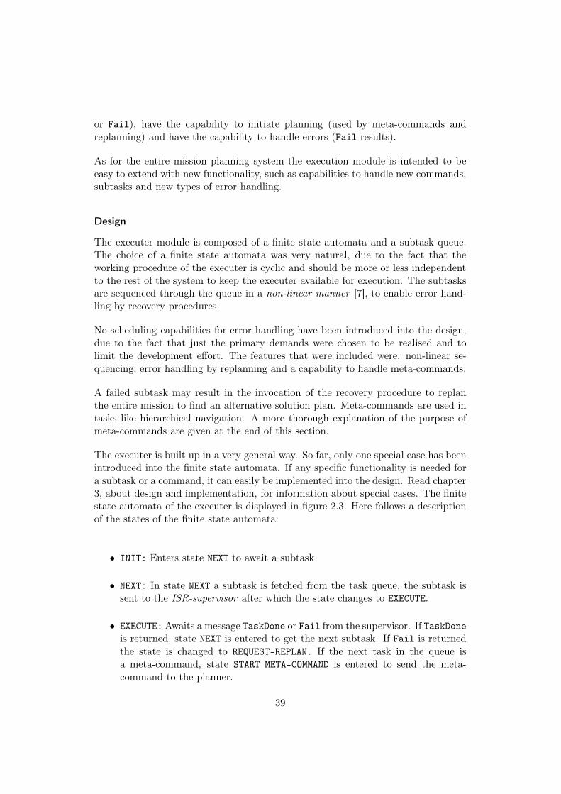
or Fail), have the capability to initiate planning (used by meta-commands andreplanning) and have the capability to handle errors (Fail results).
As for the entire mission planning system the execution module is intended to beeasy to extend with new functionality, such as capabilities to handle new commands,subtasks and new types of error handling.
Design
The executer module is composed of a finite state automata and a subtask queue.The choice of a finite state automata was very natural, due to the fact that theworking procedure of the executer is cyclic and should be more or less independentto the rest of the system to keep the executer available for execution. The subtasksare sequenced through the queue in a non-linear manner [7], to enable error hand-ling by recovery procedures.
No scheduling capabilities for error handling have been introduced into the design,due to the fact that just the primary demands were chosen to be realised and tolimit the development effort. The features that were included were: non-linear se-quencing, error handling by replanning and a capability to handle meta-commands.
A failed subtask may result in the invocation of the recovery procedure to replanthe entire mission to find an alternative solution plan. Meta-commands are used intasks like hierarchical navigation. A more thorough explanation of the purpose ofmeta-commands are given at the end of this section.
The executer is built up in a very general way. So far, only one special case has beenintroduced into the finite state automata. If any specific functionality is needed fora subtask or a command, it can easily be implemented into the design. Read chapter3, about design and implementation, for information about special cases. The finitestate automata of the executer is displayed in figure 2.3. Here follows a descriptionof the states of the finite state automata:
• INIT: Enters state NEXT to await a subtask
• NEXT: In state NEXT a subtask is fetched from the task queue, the subtask issent to the ISR-supervisor after which the state changes to EXECUTE.
• EXECUTE:Awaits a message TaskDone or Fail from the supervisor. If TaskDoneis returned, state NEXT is entered to get the next subtask. If Fail is returnedthe state is changed to REQUEST-REPLAN. If the next task in the queue isa meta-command, state START META-COMMAND is entered to send the meta-command to the planner.
39

STARTMETA-
COMMAND
NEXTINIT EXECUTE
REQUESTREPLAN
Task Done
Subtask
Next taskis a meta-command
Fail
Figure 2.3. The finite state automata of the Executer
• REQUEST REPLAN:The failed mission command is sent to the misson planneragain for replanning. When a replan request has been sent to the planner thestate changes back to NEXT to await the new plan from the planner.
• START META-COMMAND: This special case is intended to be used to initiate meta-commands. A meta-command is a command that is a part of another com-mand, issued by the user. A meta-command might be a command specificlyused only as a meta-command or it might also be a regular user-commandthat is run as a part of other commands.
In the state EXECUTE a check is performed that looks ahead on the next commandin the subtask queue. If the next subtask is a meta-command it is immediatelyissued for planning, after which the state changes back to EXECUTE. The primaryapplication of meta-commands is about hierarchical navigation planning. When therobot has reached the border of a submap, further navigation planning is needed toderive a route through the next adjacent submap. While the robot is moving to thelast navigation point (executing the second last subtask of the already planned partof the mission), further navigation planning is performed concurrently using the lastmeta-command. The planning of the meta-command should be finished before thecurrently executing subtask has terminated, to avoid that the execution stalls dueto empty task queue. This way of operation splits the mission planning effort intomultiple smaller planning tasks and delays the planning until a moment before anyplanned parts of the further mission are needed.
Section 2.5 primarily deals with error handling together with information about some
40
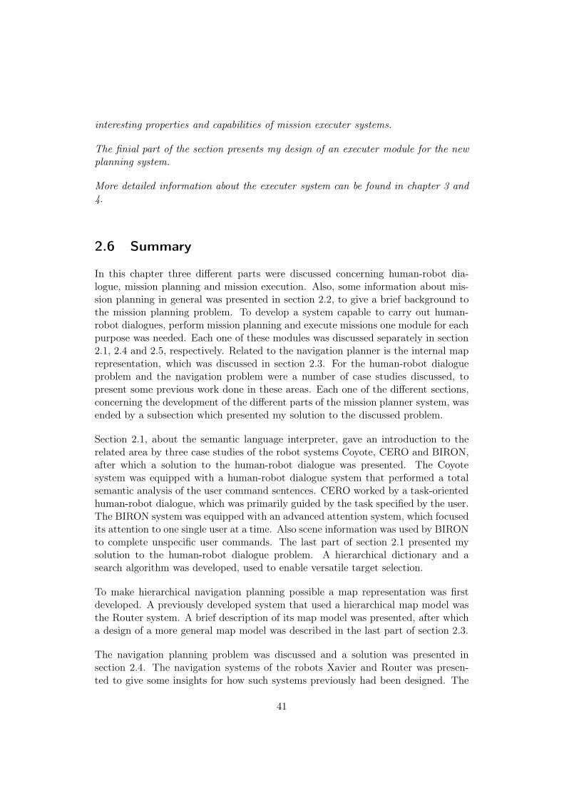
interesting properties and capabilities of mission executer systems.
The finial part of the section presents my design of an executer module for the newplanning system.
More detailed information about the executer system can be found in chapter 3 and4.
2.6 Summary
In this chapter three different parts were discussed concerning human-robot dia-logue, mission planning and mission execution. Also, some information about mis-sion planning in general was presented in section 2.2, to give a brief background tothe mission planning problem. To develop a system capable to carry out human-robot dialogues, perform mission planning and execute missions one module for eachpurpose was needed. Each one of these modules was discussed separately in section2.1, 2.4 and 2.5, respectively. Related to the navigation planner is the internal maprepresentation, which was discussed in section 2.3. For the human-robot dialogueproblem and the navigation problem were a number of case studies discussed, topresent some previous work done in these areas. Each one of the different sections,concerning the development of the different parts of the mission planner system, wasended by a subsection which presented my solution to the discussed problem.
Section 2.1, about the semantic language interpreter, gave an introduction to therelated area by three case studies of the robot systems Coyote, CERO and BIRON,after which a solution to the human-robot dialogue was presented. The Coyotesystem was equipped with a human-robot dialogue system that performed a totalsemantic analysis of the user command sentences. CERO worked by a task-orientedhuman-robot dialogue, which was primarily guided by the task specified by the user.The BIRON system was equipped with an advanced attention system, which focusedits attention to one single user at a time. Also scene information was used by BIRONto complete unspecific user commands. The last part of section 2.1 presented mysolution to the human-robot dialogue problem. A hierarchical dictionary and asearch algorithm was developed, used to enable versatile target selection.
To make hierarchical navigation planning possible a map representation was firstdeveloped. A previously developed system that used a hierarchical map model wasthe Router system. A brief description of its map model was presented, after whicha design of a more general map model was described in the last part of section 2.3.
The navigation planning problem was discussed and a solution was presented insection 2.4. The navigation systems of the robots Xavier and Router was presen-ted to give some insights for how such systems previously had been designed. The
41

Xavier system showed a method to construct a very reliable system, using probab-ilistic models. The Router system showed a way to address the navigation planningproblem using a hierarchical multi strategy-strategy navigation planner, to make thenavigation search more effective. As topological graphs frequently have been used innavigation problems a few graph theoretic shortest path algorithms were presentedin section 2.4.3. The last section described the chosen solution to the navigationplanning problem. To use the hierarchical map representation, described in section2.3, a recursive working scheme was developed to maintain a session vector overfuture navigation planning searches, which was used to perform navigation in anon-line manner.
The mission executer is needed to instruct the robot to perform different subtasksin the right order. Its is also tightly involved in mission error handling, which was ofprimary interest in section 2.5. A few sequencing and schedule repair methods werementioned. The last part of the subsection described my solutions to the problemsof mission execution and error handling, which concerned non-linear sequencing us-ing a finite state automata, hierarchical navigation planning and error handling byreplanning.
42

Chapter 3
Design and implementation
An implemented version of the mission planner system has been developed, in whichenough functionality have been introduced to realise a complete working system,capable to perform simple human-robot dialogues, navigation planning and errorhandling for mission execution. In this chapter more details are described, relatedto the choice of method for implementation. These details are presented in subsec-tion 3.1, where the design of managers for the human-robot dialogue system and themission planner system are described.
Brief discussions concerning the implementation work done is presented in section3.2. As the majority of the implementation work done, for this master’s thesis pro-ject, was done using the development tool CLIPS. A brief introduction to CLIPSis given in section 3.2.1. The following subsections in section 3.2 brings up specificimplementation details about the three subsystems (the human-robot dialogue man-ager, the planner manager and the executer manager). Finally, in section 3.2.5, anoverview of the implementation of the entire mission planner system is presented.
3.1 Finite state automatas
Previously in this report three system parts have been discussed. These are thehuman-robot dialogue system, the mission planning system and the mission ex-ecuter system. Not until a user command has been validated it is to be planned for,and not until a mission has been planned it is to be executed. After a first thoughtthis seems to be a very sequential way of operation, but when other functionalitieslike command completion dialogues and mission error handling are considered, thisway of operation turns out to be more complicated. Each of these subsystems needsto function more or less independently and concurrently to the other system parts.
To keep track of the different situations of the different subsystems, finite state auto-matas, one for the human-robot dialogue system and one for the executer system,could solve the problem of the non-sequential way of operation. In a plan generationsystem there might be several different planning algorithms for different purposes.
43

ASKUSER
WAITINIT CHECK
POST
Retry
User command
Target
specifiedbadly
Re-checkspecifications
Validcommand
Figure 3.1. Finite state automata of the Dialogue manager
Before planning, a planning algorithm must be selected. Therefore, a third finitestate automata is needed. This finite state automata is meant to perform moreadministrative work than just algorithm selection.
As described in section 2.5, the mission executer is entirely built up by a finite stateautomata, so only the finite state automatas of the human-robot dialogue systemand the mission planner system will be described in this section (3.1.1 and 3.1.2).
3.1.1 Dialogue manager
The behaviour of the dialogue manager could easily be designed using a finite stateautomata with separate states for: fetching a command line from the user, checkingthe command, trying to correct a badly specified command and posting a checkedcommand for planning, see figure 3.1. The dialogue module should be independentof the rest of the planning system, apart from its ability to post valid user commandsto the planner manager. No matter what the robot system is currently up to thedialogue module should still be free to accept and process commands from the user.For that purpose I chose to implement the dialogue manager as a separate finitestate automata.
Description of the states
Here follows brief descriptions of the states of the finite state automata, where theconditions for each transition is explained.
44

• INIT: Loads the dictionary from file and starts up the finite state automata instate WAIT.
• WAIT: Waits for and fetches a command line from user.
• CHECK: First the action of the command line is evaluated. If the action requiresa target the target is checked by the traceSpecs algorithm, displayed in table2.1.
1. If an invalid action is given by the user, the user is told to retry and thestate is changed back to WAIT.
2. If a valid action is given and a target argument is needed but the targetargument cannot be resolved into any target candidates, the user is toldto retry and the state is changed back to WAIT.
3. If a target is needed but the target is badly specified the state is changedto ASKUSER.
4. If the action and the target argument, if needed, has been approved asvalid, the state is changed to POST.
• ASKUSER: Tells the user whether the target specifications were unspecific orcontradictory specified, and asks the user to respecify the previously selectedtarget. When new specifications have been given by the user the state ischanged back to CHECK to verify the new specifications.
• POST: Posts the valid command, to the planner manager for planning, afterwhich the state is changed back to WAIT, to process the next user commandline.
The finite state automata of the dialogue manager is very general. No command-specific special cases have been defined. This makes it very easy to extend thefunctionality with new user commands. If a special case is not needed, a new com-mand word just has to be added to the list of known commands.
3.1.2 Planner manager
There are three tasks that are performed by the planner manager. The main purposeof the planner manager is to act as intermediary between the dialogue manager, theplanning methods and the executer manager, which includes to pick the next validcommand, retrieved from the dialogue manager, initiate planning and to send anewly planned mission for execution. The second task that is performed by theplanner manager is to select the correct planning method, depending on the actionspecified by the user. The last task is to carry out simple mission scheduling, whichis to insert a planned mission at the right position in the task execution sequence.As this module primarily acts as intermediary it should be independent to whatthe rest of the system is currently up to, and for that reason the planner managerhas been designed as a separate finite state automata as well, see figure 3.2. The
45

FETCHINIT PLANNING
ENQUEUE
Planning failed
Valid user command
Plannedmission
Figure 3.2. Finite state automata of the planner manager
independency is important due to the fact that the robot should be able to carryout subtasks and retrieve commands from the user simultaneously as the system iscurrently planning.
For the planner manager module to be extensible it should be possible to augmentthe system with planning algorithms with arbitrary complexity. Such algorithmsmust be run concurrently with the rest of the system, to avoid that the systemstalls. Therefore the planning algorithms should be run by a separate thread ofexecution. Read more about concurrency in section 3.2.1.
Description of the states
The states of the planner manager are described next:
• INIT: Starts up the finite state automata in state FETCH.
• FETCH: Waits for and fetches the next valid user command from the dialoguemanager.
• PLANNING: Depending on which command that is to be planned the appropriateplanning procedure is started.If the planning fails the state is changed back to FETCH. If the planning succeedsa sequence of subtasks has been retrieved and the state is changed to ENQUEUE,to schedule the sequence of subtasks for execution.
• ENQUEUE: The sequence that describes the planned mission is added to thesubtask queue, and the state is changed back to FETCH to process the nextvalid user command.
As for the rest of the system also the planner manager should be easy to extend withnew functionality and tasks. As a choice among different planning methods mustbe done by the the planner manager it is not as general as the dialogue manager orthe executer manager. Each action might have its own planning procedure.
46

3.2 Implementation
The essential parts of the planner system have been implemented entirely in the pro-gramming language CLIPS (C Language Integrated Production System) [10], whileJoining and communicative functionality was implemented in C/C++. Thereforethis section begins with a brief introduction to CLIPS, in section 3.2.1, before anyimplementation details of the planner system are discussed.
After the introduction to CLIPS, a few implementation details are brought up insection 3.2.2 - 3.2.4, concerning the different subsystems.
This section ends with an overview of the entire mission planner system and somemore information about the interfacing with the ISR-supervisor, different CLIPSenvironments and the data flows through the planner system.
3.2.1 Introduction to CLIPS
CLIPS is a Lisp-like language, especially developed for implementations of expertsystems, and is entirely implemented in C. CLIPS is primarily a rule language. Arule matches its pattern against a set of facts. A rule can be seen as an IF-THENstatement, but acts more like a WHENEVER-THEN statement, due to the fact thatthe rule patterns are evaluated continually by an inference engine. The inferenceengine runs the Rete Pattern Matching Algorithm that was specifically designed toperform a very efficient pattern matching [10].
The facts can be asserted and retracted dynamically, holding any information thata rule might match its pattern against. When a rule has matched its pattern withsome facts, it is put on the agenda for execution of the executable statements of therule [10].
CLIPS is not purely rule based, it also supports procedural and object orientedparadigms, that makes it very suitable for implementation of all parts of the plan-ner system in CLIPS [10].
Some of the advantages of CLIPS compared to C/C++ are described next; Theautomatic garbage collection within CLIPS makes it a lot easier to use than C orC++. The rule-constructs in CLIPS make it easy to implement the finite stateautomatas and to declare other rules handling special cases. This is because of theimplicit concurrency within CLIPS, in which rules are evaluated continually. Whena rule fires (gets its pattern matched to facts) its executable statements are sched-uled for execution.
One of the data types frequently used in CLIPS is the multifield. A multifield maycontain any type of information like strings, numbers and memory addresses. Manydifferent vectors, containing subtasks, navigation routes etc., are handled by the
47

planning system. These vectors could easily be stored and worked with contained inmultifields. The simplicity to use the multifields reduced the implementation effortsa lot.
The procedural possibilities in CLIPS made it possible to implement complex al-gorithms, needed by the dialogue module and the navigation planner. The objectoriented paradigms made it easy to implement custom data types, used by the maprepresentation and the dictionary. The fact that everything, which concerns thecentral functionality of the planner system, could easily be implemented in the sameprogramming language made CLIPS a very advantageous choice.
A rule that has fired is also known as an activated rule (a rule that has matchedits pattern to the currently asserted facts). When multiple activations of rules arepresent at the same time, some kind of tie breaking mechanism has to be used todecide which one of the activated rules to execute first. In CLIPS there are a numberof different conflict resolution strategies for this purpose. I chose the strategy calledthe “Breadth strategy”, which resolves conflicts by executing the rules with earlieractivations before rules with later activations. Using this strategy makes it easy touse CLIPS-facts as queues [10].
Concurrency
CLIPS can be run with one or more environments. Each environment acts independ-ently with its own data structures. Each environment allows one process thread onlyto be run. It is possible to simulate concurrency within one single environment withone single thread by counting the number of fired rules, but this demands a lot ofextra care when implementing. Simulated concurrency is also difficult to maintaininside CLIPS-functions that may tie up the running thread for a longer period oftime.
If several threads are used simultaneously in the same environment undeterminativebehaviours may occur, if no synchronisation is done. Multiple threads are not muchhelp to avoid functions that tie up the thread, due to the fact that the runningthread must leave CLIPS before another thread may enter CLIPS.
For efficient concurrency of threads, multiple environments are required. By usingmultiple environments the concurrency can be handled by the multi-threading cap-abilities native to the operating system.
For this purpose I chose to implement a solution with two CLIPS-environments. Al-gorithms that take long time to finish should not delay critical actions to be carriedout by the mission executer. For example, a STOP command that is to be sentto the ISR-supervisor should have no or negligible delay. A STOP command thatis executed, say one second too late might have devastating consequences, considerstairs going downwards.
48

3.2.2 Dialogue manager
User interaction is entirely done by a user command prompt, implemented in C/C++,via standard input/output. Input commands are sent to the dialogue manager byasserting them as CLIPS-facts. The facts, containing the user commands, make upa command queue from which the dialogue manager fetches commands.
The hierarchical dictionary is stored in a text file, using a format easily read byCLIPS, see appendix C. At system start-up, the dictionary file is read into memoryand stored as object instances of the types Group and Thing, where a Thing is aword representing an item in the world and Group is a collection of Things andGroups.
The human-robot interface (HRI) takes input from the user via keyboard and feed-back and questions for target completion is returned through a terminal window.No voice synthesis or voice interpretation have been added, due to the fact that itwas beyond the scope of this thesis, but minor work would be needed to add suchfunctionalities.
3.2.3 Planner manager
As the planner manager has a very central role in the system and handles severalinformation flows a number of queue structures are used. Four queues are used by theplanner manager. The first one, mentioned in the previous subsection, handles validuser commands and the second one is the subtask execution queue. For simplicitythe valid command queue is made up of CLIPS-facts. The subtask execution queueis a multifield, shared between the planner manager and the executer manager. Thelast two queues are used for communication between the two CLIPS environments.
When new commands are added to the system also new planning methods are likelyto be added. To direct the new command to the right planning procedure a newCLIPS-rule, in the planner manager, is needed for that purpose. This rule can alsobe used to perform some preparations of the command parameters.
3.2.4 Executer manager
The design of the mission executer was described in section 2.5. In this section someadditional implementation details are discussed.
The design of the executer manager is implemented in a general way, where noneof the states NEXT, EXECUTE, START META-COMMAND, or REQUEST REPLAN are custom-made for any specific subtask or command. When new commands or subtasks areintroduced into the system no or minor implementation work has to be done tothe executer manager. For interfacing with the ISR-supervisor some exceptions ofgenerality had to be made, concerning error handling.
49

The executer manager takes care of failed missions by trying to replan them. Theerror handling procedure: replan if a closed door is encountered, has been imple-mented to the system to demonstrate the replan error handling capability.
The ISR-supervisor is unable to send back any Fail-feedback. To demonstrate theerror handling, without any changes to the ISR-supervisor, specific support for er-ror handling for door traversals had to be implemented in the executer manager.This custom-made implementation consists of a timeout mechanism. When a doortraversal is initiated a timer is started. If the door traversal has not finished beforetimeout the door is assumed to be closed and the state of the executer manager ischanged to REQUEST REPLAN, where the replan procedure is initiated. If the ISR-supervisor had the ability to send error feedbacks this case could have been handledwithout any custom-made implementations for error handling of closed doors.
3.2.5 Overview of the planning system
The new human-robot interface and the mission planner replace the entire deliber-ative layer of the ISR system shown in figure 1.1 in section 1.2.2. The new missionplanner controls the robot by communicating with the ISR-supervisor.
When interfacing with the ISR-supervisor, ISR-specific subtask commands must beused. To realise this, each subtask derived from a planner algorithm has to betranslated into an ISR-subtask before it is added to the task execution queue. Thistranslation was carried out by a simple subtask mapping function. If this system,described in this report, is to be used in conjunction with software other than ISR,this subtask mapping function needs to be rewritten. For more details about whichmodifications that need to be done, to port the planner system to work with anotherlow level architecture than the one of ISR, see appendix D.
An overview of the new mission planning system is displayed in figure 3.3, where theconnection to the ISR-supervisor is illustrated. In figure 3.3 all arrows represent thedirection of data flow. The lower parts of the figure represent two of the softwarelayers of ISR: the reactive layer and the ISR task execution layer. The upper partshows the entire mission planner system, that has replaced the previous ISR plannersystem. To compare with the original ISR-system, see figure 1.1.
Here follows a description of the data flow through the system: The HRI commu-nication is supervised directly by the dialogue manager. The dialogue manager usesinformation from the dictionary to verify commands given by the user. When the ap-propriateness filter has approved a user command as a valid command the commandis sent to the planner manager. The planner manager determines which algorithm torun and sends the command parameters to the algorithm environment for planning.The navigation planner has been implemented in the algorithm environment, whereit uses information from the map representation. The planner manager can alsomodify the map representation by sending messages to the algorithm environment.
50

ISR-Supervisor
ISR Task Execution Layer
New Deliberate Layer
Reactive Layer of ISR
Navigationplanner
Maprepresentation
Algorithm Environment(CLIPS)
Dialoguemanager
Dictionary
Plannermanager
Executermanager
Main Environment(CLIPS)
Human-Robotinterface
Figure 3.3. Architecture of the entire mission planner system
When the planner manager has got a result back from a planning algorithm thenew mission is posted on the execution queue, used by the executer manager. Theexecuter manager executes subtasks by sending the subtask commands further tothe ISR-supervisor. When a meta-command is encountered in the task queue or amission fails, the executer manager sends a valid command to the planner managerfor planning of a meta-command or replanning of a failed mission, respectively.
The algorithm environment
The algorithm environment is only used to run demanding algorithms. The reasonfor the algorithm environment is to be able to use a second native thread of execution.All communication between the two environments are done by CLIPS-facts. Theseare sent through two queues, one for each environment, implemented in C++.
The navigation planner algorithm is implemented in the CLIPS-environmentfor algorithms. As mentioned in section 2.4.4, A* was chosen for the shortest pathsearch for each partial navigation path.
For the A* algorithm to perform well it needs two heap data structures, see table2.4: OPEN and CLOSED. Instead of using heaps I implemented A* using twoCLIPS-multifields and using the binary insert sort algorithm, which has the sametime complexity as an insert-element procedure for a heap. Elements are only read
51

and removed from the first position of the multifields, which contributes to fasteroperation than for a heap.
The map is loaded into the algorithm environment, to keep it close to the navigationplanning algorithm. As mentioned earlier it is possible to modify the map. Before areplanning is initiated a message is sent from the planner manager, to the algorithmenvironment, to remove an edge in the map to reflect a blocked passage (e.g a closeddoor).
3.3 Summary
The human-robot dialogue system, the mission planning system and the missionexecuter system had to be working concurrently to each other. For that purposethree finite state automatas were designed, including the one of the mission executersystem. The finite state automatas (the dialogue manager and the planner manager)for the human-robot dialogue system and the mission planner were described in sec-tion 3.1.
The implementation of the entire mission planner system was done using the CLIPSimplementation tool, due to a number of advantages such as: a rule based languagewith simple rule definitions, handy data types and object oriented and proceduralparadigms.
The chapter ended with more implementation specific details, concerning the dia-logue manager, the planner manager and the executer manager. The last subsectionpresented an overview of the implemented system.
52

Chapter 4
Evaluation
This chapter brings up the major differences between the new planner system andthe ISR planner system to give some ideas of the achieved improvements. The imple-mented system has been tested extensively, from which a number of capabilities andincapabilities have been noticed and are pointed out in this chapter. A few aspectsof performance of the target specification algorithm and the navigation system arediscussed, concerning runtime evaluation and optimality of navigation paths. Thelast parts of each section concerns the possibilities for future work to be done to thesubsystem discussed.
4.1 Working functionality
Let us bring up an example, which shows the potentials of the system. The outlinewill be like this; The user states a command sentence to the system, the human-robot dialogue system checks the command, the command is planned by the missionplanner and at last the mission is executed by the executer system.
Here follows a description of the initial situation; Consider that there are multipleliving rooms in the world. There is only one “floor 7” in the world. One of the livingrooms is located on this floor seven. Two tables are placed in the living room onfloor seven: a dinner table and a sofa table. One of the windows in the world islocated in the living room on floor seven. This window is close to the dinner table.The robot is initially located at position (A) in the lab, see figure 4.1. The figureshows the layout of the lab environment in which the mission planning system wastested. The different entries, illustrated in figure 4.1, are represented in the diction-ary of the dialogue system. In the dictionary different entries in the world may beassociated to each other. The associations between the different objects are shownin figure 4.2, where associations are denoted by lines. For this situation a correct,but a quite complicated, command sentence in a language similar to English couldbe:
GOTO table by the window in the living-room on floor7
53

Lab
Corridor
Work-shop
Living room
Dinner
table
Window
Sofa
table
B
A
C
E F
D
Figure 4.1. The lab environment on floor 7
All words written in italics are ignored by the command interpreter. This sentencecontains one target candidate specifier (“table”) and three target specifications (“win-dow”, “living room”, “floor7”). Each one of these words resolves into a set containingall tables in the world, all living rooms, all windows and all floors with alias “floor7”,represented by ellipses in figure 4.2. In the figure only the interesting entries in theworld are displayed, i.e. only one living room, even though there are several livingrooms in the world.
The trace algorithm, in table 2.1, is run once for each one of the target candidatesresolved from the “table” argument. Each run starts at one of the target candidates(the sofa table or the dinner table) and follows the associations, shown in figure 4.2,between the different entries in the different sets. The target candidate, at whichthe trace algorithm started, has been validated when all sets involved are covered.The sets are covered, like the nodes in a spanning tree, where one entry of eachset has been included into the spanning tree. Exactly one of the target candidatesmust be validated for an unambiguous match. The command given above resultsin a successful selection of the dinner table, even though the target was not statedexplicitly, by some unique alias.
When the command has been validated (i.e. when exactly one target candidate hasbeen validated) the command is sent to the planner manager (see section 3.1.2) forplanning. The planner manager propagates the command parameters to the rightplanning method, which is the navigation planner. The planning algorithm performsa hierarchical on-line planning, in which it searches at higher levels first (e.i. world,buildings, floors, rooms) and at last at the lowest level (positions). The nodes of the
54
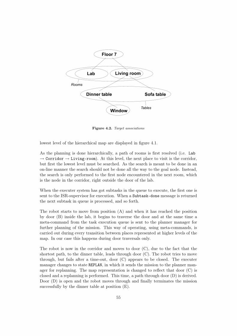
Floor 7
Tables
Rooms
Living roomLab
Dinner table Sofa table
Window
Figure 4.2. Target associations
lowest level of the hierarchical map are displayed in figure 4.1.
As the planning is done hierarchically, a path of rooms is first resolved (i.e. Lab→ Corridor → Living-room). At this level, the next place to visit is the corridor,but first the lowest level must be searched. As the search is meant to be done in anon-line manner the search should not be done all the way to the goal node. Instead,the search is only performed to the first node encountered in the next room, whichis the node in the corridor, right outside the door of the lab.
When the executer system has got subtasks in the queue to execute, the first one issent to the ISR-supervisor for execution. When a Subtask-done message is returnedthe next subtask in queue is processed, and so forth.
The robot starts to move from position (A) and when it has reached the positionby door (B) inside the lab, it begins to traverse the door and at the same time ameta-command from the task execution queue is sent to the planner manager forfurther planning of the mission. This way of operating, using meta-commands, iscarried out during every transition between places represented at higher levels of themap. In our case this happens during door traversals only.
The robot is now in the corridor and moves to door (C), due to the fact that theshortest path, to the dinner table, leads through door (C). The robot tries to movethrough, but fails after a time-out, door (C) appears to be closed. The executermanager changes to state REPLAN, in which it sends the mission to the planner man-ager for replanning. The map representation is changed to reflect that door (C) isclosed and a replanning is performed. This time, a path through door (D) is derived.Door (D) is open and the robot moves through and finally terminates the missionsuccessfully by the dinner table at position (E).
55

4.1.1 Other examples of user commands
Ambiguous or inconsistent commands might easily be issued. Consider a casewhen the user gives a command that is ambiguous with respect to the dictionary ofthe dialogue system. If the user gives the command:
GOTO table in the living-room on floor7
no single mathing word of type tablewould be derived (dinner-table and sofa-table).Both tables (dinner-table and sofa-table) are candidates for that command andboth match the specifications. This makes the dialogue system enter into a dialoguewith the user, by asking the user to give new and more specific target specifications.Consider that the user restates the specifications to “the sofa-table in the living-roomon floor7”, which results in one single match.
The opposite case is when the target specifications contradict each other. Whensuch a command is given by the user, the system also asks the user to restate thetarget specifications. Consider a case when the user tells the robot to go to a tablein a room that has no table. The system asks the user to restate the specifications,which simply could be another room.
Ownerships can be represented in the dictionary, as the associations has no spe-cific type. The requirement is that the name of a person is added to the dictionary.Let us consider a special case where an association is used as an owned-by operator.There is one room that is only used by the only person named “Anders”. In Anders’room one table is located. The table in the room is associated to the room and theroom is associated to Anders. A correct command sentence could be:
GOTO table in Anders room
Considering the described situation, the single table in the room owned by the singlehuman named Anders is an unambiguous statement, which leads to a single match-ing table.
Abstract destinations in navigation may be used instead of positions at thelowest level of abstraction. The start node in a navigation search is always a leafnode, for which the robot has information available as its current position. Thedestination on the other hand must not always be a leaf node, but may be a node ofhigher abstraction. For instance, instead of selecting a leaf node for a position insidea room the user might select the room as destination. The user wants the robot toenter that room, but which one of the positions in the room does not matter. Thiscapability is handled by the navigation planner by selecting the first encountered(closest) leaf node that has the destination node as one of its supernodes at anyhigher level. For example, the command: “goto world” would result in no actionsdone by the robot due to the fact that the robot already is located by some leaf
56

node somewhere in the world.
This section has presented the satisfactory functionality of the mission planning sys-tem, and the way of operation has been described by examples.
4.2 The dialogue subsystem
The previous planner system of ISR was purely command based. Each task wasdenoted as a single command with a set of parameters. Also the new system iscommand based, due to the fact that there is exactly one single action commandmapped to a performable action.
The major difference in the dialogue system is the target mapping abilities. Inthe ISR system a target could only be selected by predefined aliases mapped tothe target. Also synonym aliases could be defined. The new system has the samecapabilities as the ISR system concerning aliases and synonyms, but it has a moreversatile way of targeting. A target can often be stated in many different ways, byusing command sentences that are more similar to English language. This is doneby a hierarchical dictionary, where words of the same kind are grouped togetherto make it possible to express a target by the kind of the target instead of one ofan object’s aliases. As there are most probable several targets in the world of thesame kind, a target that is to be selected with a kind-of specifier must be picked outusing additional specifications. An association can be the location of the target ora proximity to another target in the world. Spatial specifications cannot be used,just the fact that two objects are associated to each other in a non-specified way,e.g. a reason for an association might be that two objects are close to each other.Particular relations demand prepositions to be used, but prepositions are completelyignored by the system, due to the fact that the evaluation of them is considered tobe a too complex task and beyond the scope of this thesis.
4.2.1 Examples of incapabilities
Two examples are brought up. The first example identifies a word association prob-lem and the second example shows the problems of neglected prepositions.
Example 1
The situations described next are critical in the implemented version of the commandinterpreter. Notice that the window has no association to the living room, see figure4.2. It would be more correct if the window in the living room was associated tothe living room, a command might be: “GOTO window in the living room”. Thiscommand would find no matching window. Instead, consider the case illustratedin figure 4.3. The association between the window and the living room is defined.This leads to a problem, as the sofa-table would also be validated as a table close to
57

Floor 7
Tables
Rooms
Living roomLab
Dinner table Sofa table
Window
Figure 4.3. Target specification issue
the window. An unspecific result would be achieved and the system would ask theuser for new specifications. This is due to the fact that the trace algorithm wouldfollow the links from the sofa table, via the living room to the window (Sofa table→ Living room → (Window & Floor7)). This example points out a limitation ofthe system. In general terms, objects at the same hierarchical level, associated toeach other, cannot be associated to the same object at a higher level.
Example 2
As no prepositions are evaluated by the dialogue system there is no way to de-termine which kind of association two different objects have. The situation mustbe unambiguous enough to avoid the importance of different types of associations.Two objects that both are associated to a common object, but for different reasons,would lead to a problem. For example, consider the command sentences:
pick-up object beside the tablepick-up object on the table
which are both interpreted as the same target object. If both objects exist, besideand on top of the table, both commands would be considered as ambiguous by thesystem. This was an example with spatial relations, in which the importance ofprepositions is obvious.
4.2.2 Performance
The specification trace algorithm was run with different sizes of the dictionary andwith a varying number of word associations. The runtime for each test was measured.Table 4.1 displays a selection of the collected runtime data for a command with
58
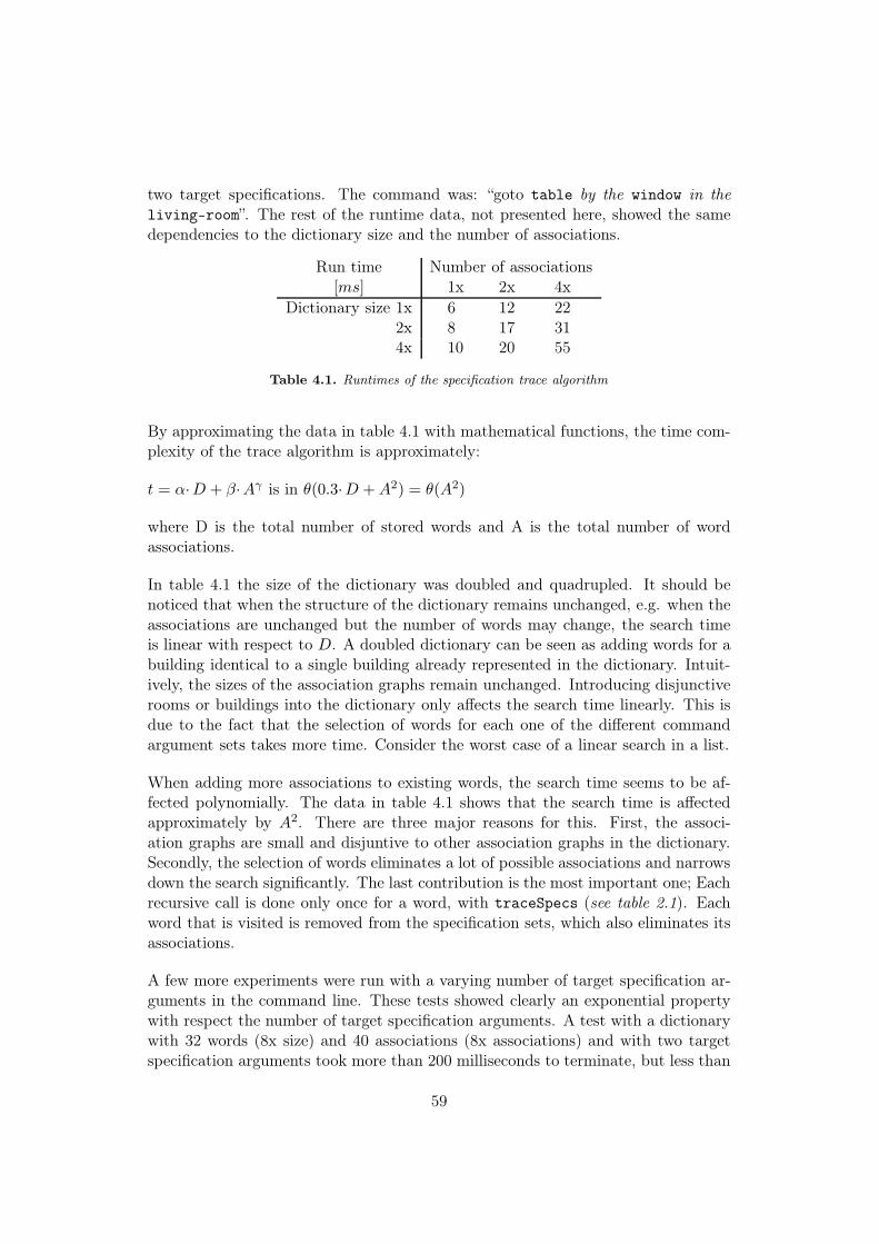
two target specifications. The command was: “goto table by the window in theliving-room”. The rest of the runtime data, not presented here, showed the samedependencies to the dictionary size and the number of associations.
Run time Number of associations[ms] 1x 2x 4x
Dictionary size 1x 6 12 222x 8 17 314x 10 20 55
Table 4.1. Runtimes of the specification trace algorithm
By approximating the data in table 4.1 with mathematical functions, the time com-plexity of the trace algorithm is approximately:
t = α·D + β·Aγ is in θ(0.3·D +A2) = θ(A2)
where D is the total number of stored words and A is the total number of wordassociations.
In table 4.1 the size of the dictionary was doubled and quadrupled. It should benoticed that when the structure of the dictionary remains unchanged, e.g. when theassociations are unchanged but the number of words may change, the search timeis linear with respect to D. A doubled dictionary can be seen as adding words for abuilding identical to a single building already represented in the dictionary. Intuit-ively, the sizes of the association graphs remain unchanged. Introducing disjunctiverooms or buildings into the dictionary only affects the search time linearly. This isdue to the fact that the selection of words for each one of the different commandargument sets takes more time. Consider the worst case of a linear search in a list.
When adding more associations to existing words, the search time seems to be af-fected polynomially. The data in table 4.1 shows that the search time is affectedapproximately by A2. There are three major reasons for this. First, the associ-ation graphs are small and disjuntive to other association graphs in the dictionary.Secondly, the selection of words eliminates a lot of possible associations and narrowsdown the search significantly. The last contribution is the most important one; Eachrecursive call is done only once for a word, with traceSpecs (see table 2.1). Eachword that is visited is removed from the specification sets, which also eliminates itsassociations.
A few more experiments were run with a varying number of target specification ar-guments in the command line. These tests showed clearly an exponential propertywith respect the number of target specification arguments. A test with a dictionarywith 32 words (8x size) and 40 associations (8x associations) and with two targetspecification arguments took more than 200 milliseconds to terminate, but less than
59

20 milliseconds with one target specification.
As mentioned in section 2.1.2, the specification trace problem is a kind of spanningtree problem. A pure minimal spanning tree problem is solved in polynomial time.The worst case of Prim’s minimal spanning tree algorithm is in θ(n), where n isthe number of nodes in the graph. Kruskal’s minimal spanning tree algorithm is ino(m log(p)(m)), where m is the number of edges in the graph and p ≥ 0 (example:log(3)(m) = log(log(log(m))) [1].
The specification trace problem is quite different from a pure spanning tree problem,due to the fact that each node in the spanning tree consists of several words thatare evaluated recursively. For each node (specification argument) that is visited, bythe traceSpecs-algorithm, each one of the selected words of the node is evaluatedby a recursive call. The number of possible spanning tree solutions increases expo-nentially with respect to the number of specification arguments, due to the fact thatthere are multiple words in each node.
4.2.3 Extensibility
Throughout the project scalability has been one of the major ambitions, i.e. newcommands and new functionality should be easy to add to the system.
A command word (a verb) is simply added to one of the lists describing knowncommands. A word (a noun) representing an object in the world is easily added tothe system by adding a line to the dictionary file, which relates the new word to agroup and a real item in the world. In this line can also synonyms be specified.
For special cases new CLIPS-rules must be added to the state “Check” of the dialoguemanager. Also command specific states of the dialogue manager might be added.
4.3 Navigation planning subsystem
The map representation, used by the ISR system, consisted of a topological graph.It has been expanded into a hierarchical map representation consisting of multipletopological navigation graphs at different levels of abstraction.
Each node in the topological graph of the ISR planner system, represented a room.Each room could have a set of navigation positions and door positions. Between thepositions in a room a customised navigation graph could not be specified. Insteadcomplete navigation graphs were used, which left the navigation problem, inside aroom, to be solved completely by the lower levels of the system architecture. Thisis not a very good solution if there is some permanent obstacle somewhere in theroom that the robot has to go around. it would be better if the robot could followa path in a map of the room.
60
The map representation of the new planner system is more general than the maprepresentation of the ISR-planner. A navigation graph inside a certain room canbe custom-made, which also permits complete navigation graphs to be defined ifnecessary.
One of the most distinct improvements done to the new system is for rooms withmultiple doors. Several doors between a pair of rooms could not be handled bythe ISR planner. This is due to the fact that there was no way for the system todecide which door to choose when moving to the next room. To solve this problemsome extra information would be necessary, that would help the system to decidewhich door to traverse. The new planner system solves this problem implicitly bydelegating the navigation planner to make the decision, with respect to the distanceto the next room and the distance to the destination node.
4.3.1 Examples of incapabilities
A navigation search in a hierarchical navigation map with equal max-depth through-out the entire map generates a solution path if one exists. It is not guaranteed tobe an optimal path because of the hierarchical properties. Read more about theoptimality issue in subsection 4.3.2. The navigation search is performed in a hier-archical manner, which means that further search is done when needed, dependingon the structure of the map. This permits efficient on-line planning due to the factthat details are ignored at the higher levels. This is only true if the map is designedwith partial navigation graphs of appropriate sizes, i.e. equal branching, see section4.3.2.
Here follows a couple of examples concerning problems with the implemented versionof the navigation planner.
Example 1
Consider that the map has different depths of its leaf nodes, which would be feasiblefor a world including several different types of environments. The system does notwork with navigation maps with varying depth of leaf nodes, due to the fact thatthese cases of generality were not considered during the implementation. Whenstarting at a higher level leaf node than the destination node the search terminatesbefore a search is done at the lowest level of the destination. A mission containingonly an abstract solution is derived, but is not detailed enough for navigation.
When starting at a node at a lower level than the destination leaf node, a followingpartial search will fail before a path to the goal is found. This is due to the fact thatthere are no nodes at such a low level as the level of the start node, but a node atthat level is required.
61

Figure 4.4. Room passage problem
Example 2
Blocked passages like closed doors are handled by replanning to find an alternativesolution path. This might also be used for the general case if some obstacle in anarea (in a room) blocks the robot to go from one place to another. Consider the casewhen the robot shall move inside a single room, but the path is blocked by someobstacle. Imagine that the only alternative solution is to leave the room through onedoor and enter the room again through a second door, to get around the obstacle. Ifsuch a solution exists it would not be found by the planner system. The navigationsearch algorithm cannot search outside a supernode that holds the goal node.
4.3.2 Performance
Optimality of routes
The navigation planning is done in a hierarchical manner that splits the planningwork into multiple smaller search tasks. This way of working on-line has two sig-nificant advantages; First, the search effort decreases significantly as each search isdone in a smaller subgraph. Secondly, in case of a replanning issue, just a part ofthe search has so far been done, before replanning is needed and the path must bediscared. If the search had been done from the start node all the way to the goalnode, a larger part of the search effort would have been done without progress.
The most obvious disadvantage of hierarchical planning concerns overall mission-optimal passage through a room. Consider the case where each room is representedin the map by a node at a higher level of abstraction, which is the natural choicefor a model of a building. There are also different solution paths through differentdoors, but only one solution path is optimal. See figure 4.4.
62

When the robot shall go from room (I.) through room (II.) to a goal position (G)in room (III.) the navigation planner first plans at the abstract levels and then atthe lower levels. First an abstract path, made up of rooms, is created (I. → II. →III.), but this abstract path has no detailed information about how the robot shouldmove, it just specifies which rooms to visit in which order. Finially the level of leafnodes is searched, where one search is carried out in each room, when further plan-ning is needed when the robot enters the next room. Without any comprehensiveinformation there is no way for the planner to determine which doors to traverse toand from room (II.), to achieve the optimal path. First, consider the case when therobot starts at position (S), which is assumed to be at equal distances to the twodoors of room (I.). In this case the heuristic function of the A*-algorithm wouldguide the robot to the door closest to the goal position (G), which would result in theoptimal path. If the robot would start at position (A) or (B), two different solutionpaths would be achieved, due to the fact that the planning algorithm searches forthe shortest path to the next room (II.). When starting at position (A) a suboptimalpath is achieved. The longer path in room (II.), around the permanent obstacle,is not yet considered by the navigation planner until the robot already has enteredroom (II.).
Runtime
To evaluate the runtime of the hierarchical navigation search four different mapswere used. The four maps represented the same structure at the level of leaf nodeswith 27 nodes, but the different maps had varying number of levels. The first mapwith one level only (no branching), the second had two levels (lesser branching), thethird had three levels (equal branching; i.e. the max depth equals the number ofbranches at each node), the third map had six levels (maximum number of levels).
The runtime for the same route in the different maps was measured. When us-ing branching maps, multiple searches are performed, for which the runtimes aresummarised to get the total time.
Short route Long route[ms] # searches Ratio [ms] # searches Ratio
No branching 22 1 22 67 1 67Lesser branching 26 2 13 70 3 23.3Equal branching 37 3 12.3 75 5 15Max branching 70 6 11.6 167 11 15.18
Table 4.2. Runtimes of the hierarchical navigation algorithm
The maps used in these tests contained 27 (33) leaf nodes only. The primary reasonfor the usage of such small maps was due to the fact that a lot of work effort wasneeded to define the test maps. For example, a full equal branching map with a
63

max depth 4 would hold 44 = 256 leaf nodes plus 84 nodes at the higher levels. Noautomatic hierarchy partitioner has been implemented, thus manual construction ofmaps was necessary.
In table 4.2 the runtimes and the number of searches done are presented, togetherwith the their ratio (runtime/searches). This data tends to show that planninglonger routes the equal branching distribution is the most promising, consideringthe ratio. The low search time achieved using the no branching map instead ofbranching maps, is probably due to the fact that the map has too few nodes andthe administrative work performed when using branching maps is significant due tothe low number of nodes. The maps used had a quite low number of edges betweenthe nodes, which might favour the non-branching map.
The the navigation search uses the A* algorithm. The mean complexity E(Z) of theA* algorithm, reduces to a polynomial only when the likelihood that the heuristicdistance measure h coincides with h∗ (the actual distance to goal) is sufficiently highat all nodes [13]. This leads to the average complexity:
E(Z) =
Ω(cn), c > 1 if P (h = h∗) < 1 − 1/bO(n2) if P (h = h∗) = 1 − 1/bO(n) if P (h = h∗) > 1 − 1/b
(4.1)
where b is the number of children nodes to be visited from each parent node expan-ded [13].
For our navigation case, suppose that the polynomial complexity O(n2) is achievablefor the A* algorithm and the submaps to be searched are distributed in an equalbranching manner. For such a map let N represent the number of leaf nodes and themaximum hierarchical depth is m and the number of branches at each supernode ism. Therefore, in the equal branching case, the relation N = mm is true, and themaximum number of navigation searches is s = m0 +m1 + ...+mm−1, which is thenumber of supernodes in the map.
Let us assume that the hierarchical administrative execution efforts are neglect-able. Then each partial search is in O(m2), as each supernode has m subnodes. Amaximum number of s partial searches may be performed in a mission. The totalcomplexity is therefore:
O(s·m2) = O((m0 +m1 + ...+mm−2 +mm−1)·m2) = (4.2)= O(m2 +m3 + ...+mm +mm+1) = (4.3)= O(mm·m) = O(N ·m) (4.4)
which is less than quadratic complexity and obviously faster than the non-hierarchicalA*. If N is large then N m and the worst case approaches linear time complexity.
To conclude from this and the results from the experiments, displayed in table 4.2,
64

the larger maps used the more search gain per partial search is achieved, if equalbranching is applied.
4.3.3 Extensibility
The map can easily be extended with new nodes (supernodes, and leaf nodes), byediting the map file, using the syntax of CLIPS-facts. The hierarchical structuredemands that manipulations to the map are done with care so that errors are notintroduced into the map.
To add planning capabilities for new commands new definitions of CLIPS-rules areneeded. There must be a rule that recognises the new command and sends its para-meters further to some planning algorithm. This algorithm should be implementedin the CLIPS environment for algorithms, to be run concurrently with the rest ofthe system.
There are a few things to consider for a new command. Should the command bequeued, to be executed after other commands already queued, or should it be ex-ecuted directly? Imagine a STOP command, that should be executed directly. Thenew rule should assign a DIRECTLY flag to the command if it should be executedimmediately.
If the planning algorithm is working in a hierarchical manner, maybe meta com-mands can be used to initiate further planning. For that META-tagged tasks shouldbe added to the task sequence, by the planning algorithm. In the general case theunmodified planner manager can handle the new command in a general way.
4.4 The planner and executer managers
The major difference between the executer of the ISR system and the new executersystem is the error handling capabilities of the new system. The ISR system had noerror handling capabilities at all. If a subtask failed, the entire mission was aborted.In contrast to the ISR-system the new executer system is able to issue commandsfor replanning and to initiate further planning for the hierarchical navigation.
To be able to handle the hierarchical navigation the meta-command capability ofthe executer manager was implemented.
4.4.1 Examples of incapabilities
The implementation of the new system has a flaw that makes queuing of user com-mands to work badly. When a mission is currently executing and a new commandis given by the user, the new user command is planned for immediately, using thecurrent situation instead of the future situation, which is reached when the currentlyexecuting mission has finished. In navigation this new mission has the wrong start
65

position. Instead the planning of the new user command should start when thecurrently executing mission has finished. The error is not entirely in the executermanager but also in the planner manager. Extra support for that must be imple-mented to get this working.
No support for riding lifts has been implemented. For that, is should be possibleto switch to different coordinate systems, which demands the co-ordinates to bechanged in the ISR-supervisor by some message from the planner.
The capability to exploit opportunities requires sensor data. The sensor informationis not directly reachable by the planner system. To make that possible more work,except the exploit capability, must be done to interface with the lower level layer ofthe ISR system.
4.4.2 Extensibility
The planner manager and the executer manager work close to each other. Bothmanipulate the task queue, but the executer is implemented in a more general waythan the planner manager.
The reason to increase the functionality of the executer manager would be to handlenew messages from the lower layers of the system or new mission sequencing tasks,such as features related to mission re-scheduling and other error handling capabilit-ies.
As mentioned earlier the replanning procedure was implemented in a general way,which makes it easy to use in other situations and with other commands than justdoor traversals and the command GOTO. When a fail signal is received the stateof the executer manager is changed to replan, that issues the failed command tothe planner manager for replanning. In the planner manager it is most truly thatcommand specific measures have to be performed before the replan can start. One ofthese measures might be to make the previous failed solution impossible to achievea second time, to force the system to find a new alternative solution.
4.5 Summary
To summarise, all the functionality presented in section 1.2.1 have been partiallyrealised and demonstrated successfully, by smaller examples of solutions to each oneof the different problem areas: human-robot dialogue, navigation planning and mis-sion execution.
A more versatile way of target selection was achieved by using a hierarchical worddictionary to make it possible to define associations between different entities in theworld, which enabled the use of a command language more similar to English. The
66

new navigation system is based on a hierarchical map representation, that enablethe planning to be divided into smaller parts, which is suitable for on-line planning.When a locked passage has been identified the executer system has the ability tosuccessfully initiate replanning, to derive an alternative path.
Run time evaluations of the specification trace algorithm and the hierarchical nav-igation method was presented. The specification trace algorithm has exponentialproperties with respect to the number of specifications given by the user. The prop-erties of the A* algorithm and results from experiments have identified that thehierarchical navigation search is more efficient than a non-hierarchical search. As aconsequence of the hierarchical map structure, there are situations when the navig-ation planner does not return the optimal shortest path to the goal position.
All parts are extensible within the context of mobile service robots, concerning theabilities to perform fetch and carry missions. Several of the implemented solutionshave minor flaws or limitations, as some parts have been delimited to decrease thedevelopment and the implementation efforts. A few suggestions to solutions to theseissues and limitations are briefly described in section 5.2.
67
Chapter 5
Conclusions
5.1 Summary
This thesis has described the work done to develop and implement a new missionplanner system for an existing mobile robot system. The intentions for the develop-ment of the new system, compared to the previous system, was to achieve a systemwith more functionality and scalability in human-robot dialogue, hierarchical nav-igation planning and error handling for mission execution.
The new dialogue system was designed with a more flexible target selection system,capable to select targets by command sentences more similar to English language.To achieve a more versatile system than that would require evaluation of Englishprepositions, which is considered a too complex task. The solution of target selec-tion was limited to a representation of non-specific associations between dictionarywords, representing items in the environment.
The most important work done was to the actual planner subsystem concerningnavigation planning. The most effective planning systems are specialised planners,which are capable to solve one specific planning task only. In contrast, general plan-ners work without assumptions about the problem domain and are thus less effectivethan specialised planners, such as the A*-algorithm.
An on-line planner completes each planning session efficiently enough for the plan-ning algorithm to be run, several times, while the mission concurrently is executing.Hierarchical planners may be considered as on-line planners if the hierarchical struc-ture model, in which planning takes place, is divided up by a proper granularity.
To make the mission planner system complete a mission executer module had to bedeveloped. The new executer system is a very simple solution, in which execution isdone in a non-sequential fashion, which means that depending on the result of theexecution of a subtask the executer is capable to perform different procedures. Oneof these procedures is error handling by replanning, which is used when a mission
68

fails. In the implemented executer system replanning was initiated when a closeddoor blocked the a planned path.
The developed system design, described in chapter 2, was implemented using threefinite state automata, that operate more or less independently of each other. Thethree finite state automatas handles the human-robot dialogue system, planningmanaging and mission execution, respectively. The major reason for the usage offinite state automatas is that they are easily extended with new functionality, per-formable by the robot. The entire system was implemented using the expert systemtool CLIPS [10], which was very suitable for the implementation of the mission plan-ner system.
When the system had been implemented it was tested consistently to evaluate whichof the capabilities of the system that functioned satisfactory and which functional-ities that were missing and should have been added to the system to make it usablein practice.
5.2 Suggestions to future work
Here follows a list of unsolved problems of the system. Each problem has been givena brief suggestion for a solution.
• Consider the problem discussed in section 4.2.1, where objects in a room ap-pear to be directly associated to each other but are actually associated throughmultiple links via the room entry, which is associated to all objects in the room.
A simple solution to this might be to use directional instead of bidirectional as-sociations in the dictionary. This would define a hierarchical structure betweenthe items in a room and the room itself. A more appropriate solution wouldbe to take prepositions into account (e.g. in, on, by, at) and map them todifferent types of associations.
• Items that are of the same dictionary group (e.g. tables) and are associated toeach other leads to a problem of "unspecific answer" from the dialogue system,if that group is given by the user as a target specification.
Each word that is visited by the specification trace algorithm is removed fromthe specification sets. To solve this problem the current word together withall words of the same group in the current specification set should also beremoved.
• Hierarchical navigation has a problem of locality, where solutions at higherlevels exist but the planner lacks subjective reasoning to find the optimal path.At lower levels, in the proximity of the robot, the planner lacks objective reas-oning, as the planner cannot perform planning outside the current supernode.There are two examples for these cases, respectively: a mission that involves
69

passages through rooms, needs subjective reasoning, and the ability to findan alternative solution by leaving a room and enter it again through anotherdoor, requires objective reasoning.
A possible solution for the lack of subjective reasoning might be to store extrainformation at each super node, that tells which pair of entry and exit nodesto use when passing through a non-leaf node, to derive an optimal path.A solution for the lack of objective reasoning might be to let the planner, whenno solution can be found, to perform a navigation search at the level of leafnodes, without any concern of the hierarchical structure.
• To avoid redundant information to be stored the navigation map and thedictionary, should be merged into a single data structure.
• A more efficient way of storing synonyms would be the usage of linked objectsinstead of a list.
5.3 Conclusions
The new system has improved functionality concerning human-robot dialogue, hier-archical navigation planning, error handling by replanning and is easily extensibleconcerning all parts of the system.
It is obvious that the human-robot interface lacks functionality for handling inputsin pure English. The user input language may still be similar to English even thoughall prepositions are ignored. The most important impact of the improvements tothe human-robot interface is that the user do not need to remember all differentaliases, previously used to select different targets in the world. He or she can selecta target successfully by forming a customised sentence, describing a target by itsassociations. How well this works has not yet been evaluated on a greater scale, butresults from a user study would be interesting using a very detailed and realisticdictionary for a larger environment. The developed solution is a fairly good trade-off, with respect to its capabilities and the lesser focus devoted to the human-robotdialogue problem.
It is clear that the hierarchical navigation approach is suitable for on-line planning,especially for missions that would involve very large navigation routes with a signi-ficant number of navigation subtasks. It has a few flaws, coupled to the hierarchicalsearch, but these are considered to be of less significance due to the fact that I con-sider it to be rather easy to improve the navigation planner, by considering somespecial cases.
The lower layers of the ISR architecture are still in use by the new mission plannersystem without any modifications made to these parts of ISR. This has lead to thatthe implementation of the new mission planner system has very few ISR-dependent
70

parts. This makes the mission planner easy to adapt for usage with other systemsthan ISR.
71

References
[1] Baase S.; Van Gelder A. Computer algorithms: Introduction to design andanalysis. Addison-Wesley, third edition, 200.
[2] Mchugh J. A. Algorithmic graph theory. Prentice-hall International, Inc., 1990.
[3] Zanuttini B. Introduction to propositional logic.Web-page (visited August 2004):http://users.info.unicaen.fr/~zanutti/old/logic.htm, October 2003.
[4] Arkin R. C. Behavior-based robotics. The MIT Press, 1998.
[5] Skubic M.; Perzanowski D.; Blisard S.; Schultz A.; Adams W.;Bugajska M.; Brock D. Spatial language for human-robot dialogs. IEEE Trans-actions on systems, man, and cybernetics - PART C: Applications and reviews,Vol. 34, No. 2, May 2004.
[6] Goel A.K.; Ail K.S.; Donnellan M.W.; Gomez de Silva Garza A.; Callantine T.J.Multistrategy adaptive path planning. Expert, IEEE Vol. 9 Issue: 6, Dec. 1994.
[7] Gat Erann. Non-linear sequencing. In Proceedings of the IEEE AerospaceConference, 1999.
[8] Koenig S.; Simmons R. G. Artificial intelligence and mobile robots - editorsKortenkamp D.; Bonasso R. P.; Murphy R., chapter Xavier. AAAI Press /The MIT Press, 1998.
[9] Li S.; Kleinehagenbrock M.; Fritsch J.; Wrede B.; Sagerer G. "biron, let meshow you something": Evaluating the interaction with a robot companion. InIEEE International Conference on Systems, Man and Cybernetics, volume 3,pages 2827– 2834, Oct 2004.
[10] Riley G. CLIPS - A tool for building expert systems.Web-page (visited January 2005):http://www.ghg.net/clips/CLIPS.html, January 2005.
[11] Andersson M. 0; Orebäck A.; Lindström M.; Christensen H. I. ISR: An Intel-ligent Service Robot. Technical report, Royal Institute of Technology - Centrefor autonomous systems, year n/a.
72

[12] McCarthy J.; Hayes P. J. Some philosophical problems from the standpointof artificial intelligence. In Machine Intelligence, volume 4, pages 463–502.Edinburgh University Press, 1969.
[13] Pearl J. Heuristics - Intelligent search strategies for computer problem solving.Addison-Wesley publishing company, 1984.
[14] Hüttenrauch H.; Green A.; Norman M.; Oestreicher L.; Severinson Eklund K.Involving users in the design of a mobile office robot. IEEE Transactions onsystems, man, and cybernetics - PART C: Applications and reviews, Vol. 34,No.2, May 2004.
[15] Wauchope K. Eucalyptus: Integrating Natural Language Input With a GraphicalUSer Interface. Technical report, NRL/FR/5510-94-9711, Naval Research Lab.,Washington DC, 2000.
[16] Beetz M.; Bennewitz M. Planning, scheduling and plan execution for autonom-ous robot office couriers. In Proceedings of the workshop "Integrating Planning,Scheduling and Execution in Dynamic and Uncertain Environments", 1998.
[17] Garshol Lars M. BNF and EBNF: What are they and how do they work?Web-page (visited January 2005):http://www.garshol.priv.no/download/text/bnf.html, July 2003.
[18] Koenig S.; Likhachev M. Incremental A*. In Advances in Neural InformationProcessing Systems 14. Bradford Books, 2001.
[19] Georgeff M. P. Readings in Planning - editors Allen J.; Hendler J.; Tate A.,chapter Part I - Planning. Morgan Kaufmann Publishers Inc., 1990.
[20] Zelek J. S. Human-robot interaction with minimal spanning natural languagetemplate for autonomous and tele-operated control. IEEE Intelligent Robotsand Systems, 1997. IROS ’97., Proceedings of the 1997 IEEE/RSJ InternationalConference on, Vol. 1, Sept. 1997.
73

74

Appendix A
Example of a human-robot dialogue
Here follows a human-robot dialogue, from a run of the system, where the differentsituations of dialogues are exemplified.
>> goto labMission started: goto [ml]Executing task: goto [lrDP1] ... Subtask done.Meta-task queued for planning.Executing task: goto [c7DP2]Going through door. ... Subtask done.Executing task: goto [c7P2] ... Subtask done.Meta-task queued for planning.Executing task: goto [mlDP1]Going through door. ... Subtask done.
>> goto tableYour target description was unspecific.Please, describe ’table’ in a clearer way.>> in livingroomYour target description was unspecific.Please, describe ’table’ in a clearer way.>> the sofa-tableMission started: goto [lrT2]Meta-task queued for planning.Executing task: goto [c7DP1]Going through door. ... Subtask done.Executing task: goto [c7P1] ... Subtask done.Meta-task queued for planning.Executing task: goto [lrDP1]Going through door. ... Subtask done.Executing task: goto [lrP1] ... Subtask done.
75

>> goto table by the window in the office on floor7Mission started: goto [lrT1]Executing task: goto [lrP2] ... Subtask done.
>> goto corridorYour target description was unspecific.Please, describe ’corridor’ in a clearer way.>> on floor7Mission started: goto [c7]Executing task: goto [lrDP1] ... Subtask done.Meta-task queued for planning.Executing task: goto [c7DP2]Going through door. ... Subtask done.
>> goto livingroomMission started: goto [lr]Meta-task queued for planning.Executing task: goto [lrDP1]Going through door.TIMEOUT!!Replanning goto!!Mission started: goto [lr]Executing task: goto [c7DP4] ... Subtask done.Meta-task queued for planning.Executing task: goto [lrDP2]Going through door. ... Subtask done.
>> jumpto GODUnrecognised task. Please try an other command.
>> goto GODI don’t recognize that target. Please try again.
>> goto dinner-table in the labNo match for a target like ’dinner-table’ was found.Please, describe the target in a non-contradictory way.>> in the livingroomMission started: goto [lrT1]Executing task: goto [lrDP2]>> stopExecuting task: stop ... Subtask done.
76

Appendix B
Planning using POMDPs
This appendix gives some insights of position determination and navigation usingpartially observable Markov decision process models.
A POMDP consists of different sets of entities and functions that operate on thesesets. The sets are:
• s ∈ S, S is a finite set of states
• o ∈ O, O is a finite set of observations
• a ∈ A(s), A(s) is a finite set of actions a that can be executed in state s
The functions are:
• π(s), π is the initial state distribution andπ(s) denotes the probability that s is the initial state.
• p(s′|s, a), denotes the transition probability that the actiona in state s leads to state s′
• q(o, s), denotes the probability that observation o is made in state s
• r(s, a), denotes the finite immediate reward achieved whenexecuting action a in state s
The world is discretised into an occupancy grid, typically with one-meter cells. Therobot’s orientation in the world is discretised as well. Xavier has four main directions.Each pair of a position and an orientation is represented in the POMDP as a state.A POMDP process is in exactly one state at a time where its initial state is denotedby the probability p(s1 = s) = π(s). The POMDP works at discrete time steps inwhich it carries out a state transition by executing an action.
Four stages describe how a POMDP executes.Initially, assume that st = s1.
77

1. At time t an observation ot is generated at state s withprobability p(ot = o) = q(o|st)
2. An action decision maker chooses an action at from A(st)
3. Immediate reward is received from the executed action, rt = r(st, at)
4. The POMDP changes to state st+1 in the next time step t+1, with probabilityp(st+1 = s) = p(s|st, at)
These four stages are repeating iteratively when the system is running.
For a completely observable Markov decision process model, in contrast to a POMDP,an observer is someone who observes all the information stated above, including ac-tions at, observations ot, states st and immediate rewards rt. For the POMDP,which is only partially observable, observers cannot observe the state or immediatereward of the process, and thus cannot be sure about the current state and whichthe most profitable action is.
An important property of a POMDP is that the probabilities of generated obser-vations only depend on the state st, but not on how state st was reached. Thefollowing events only depend on the current state, not on earlier events. This isknown as the Markov property [8].
Position determination
Determination of the position of the robot cannot be done exactly, due to the factthat observers have no access to information about the current state. Instead, thecurrent state of the POMDP must be estimated. The information used in theestimations are either probability distributions from earlier time steps or the resultsfrom environment observations. The probability distribution denotes α(s), wherethe initial distribution is α(s) = π(s). The probability distribution before and aftera transition denotes αprior(s) and αpost(s) respectively.
The current probability distribution can be calculated from previous probabilitydistributions by applying Bayes’s rule incrementally for each time step [8].
αpost(s) =1λ
∑s′∈S|a∈A(s′)
p(s|s′, a)αprior(s′) (B.1)
The distribution can also be calculated by using information from observations.
αpost(s) =1λq(o|s)αprior(s) (B.2)
λ is a normalisation constant to maintain∑
s∈S α(s) = 1.
78

Navigation planning
Path planning is carried out by generating a policy. Due to the fact that the robotcannot be sure about the current state, the POMDP is transferred into a completelyobservable Markov process model. In the observable case we define equations vφ(s)that represent the expected reward when starting at state s and following the policyφ to the goal position. This equation is called Bellman’s equation:
vφ(s) = r(s, a) + γ∑s′∈S
p(s′|s, a)v(s′) (B.3)
where s is the current state and s′ is the succeeding state. Assume γ < 1 to achievefinite rewards. To generate an optimal policy * we try to maximise this function forall s ∈ S, which forms a system of |S| equations:
v∗(s) = maxa∈A(s)
r(s, a) + γ∑s′∈S
p(s′|s, a)v(s′) (B.4)
An optimal policy can be calculated incrementally by value iteration of the Bellmanequations. The Bellman equations converge to v∗(s) after sufficiently many itera-tions. The decision maker selects, with respect to the optimal policy and the currentstate s, the best action according to:
a(s) = argmaxa∈A(s)
r(s, a) + γ∑s′∈S
p(s′|s, a)v∗(s′) (B.5)
When planning, the distribution of the POMDP is first, derived by eq. B.1 or B.2,transformed into a completely observable Markov process model. After that, valueiteration (eq. B.4) is carried out, after which the achieved policy is transformedback into a POMDP policy [8].
The calculation of an optimal policy is a computational demanding task, but thereare some greedy methods that provide solutions good enough for robot navigation:The most likely state strategy, The voting strategy and The completely observableafter the first step strategy [8].
79

Appendix C
File formats
This appendix describes the file formats used to store the dictionary for the human-robot interface and the map used for navigation.
C.1 Dictionary
C.1.1 Group
Syntax of the group statement:
group <unique label> <supergroup> (<synonym>*)
A group must be assigned a unique label, as an internal reference. The supergroupparameter must be specified to denote which supergroup the group is a member of.The last parameter assigns a set of synonyms for the group. The first line in thedictionary file must define a group, which is a member of the abstract supergroupnil.
C.1.2 Thing
Syntax of the thing statement:
thing <unique label> <super group> (<association>*) (<synonym>*)
A thing must be assigned a unique label and be a member of a group. The thirdparameter defines a set of associations to other thing-instances. In the dictionaryfile, a thing to be associated must precede the associating thing. The associationsare then stored as bi-directional associations. The last parameter assigns a set ofsynonyms for a thing.
Both the group and the thing have voluntary parameters, but the parenthesescannot be left out.
80

C.2 Navigation map
The file is read by CLIPS as a collection of CLIPS deftemplates.
C.2.1 Node
Syntax of the node statement:
(node (name <unique name>) (supernode <node-name>) [(pos <x> <y>)][(edge <node-name>*) (cost <number>*)] [(door <door-name>)][(subnode <subnode-name>*)] [(angle <number>)] )
The name and supernode parameters are obligatory, while the rest of the parametersmay be omitted.
A supernode with name world must be defined, which has no supernode. All othernodes must be children, directly or indirectly, to the world node.
All coordinates defined using the pos parameter are local to its supernode. If posis omitted origin is selected as default.
The edge and the cost parameters depend on each other. The list of edges must becompleted with a list of cost values, specified in a common order.
One door may be assigned to a node using the door parameter.
If no subnodes are defined using the subnodeparameter, the node is considered tobe a leaf node. Supernodes and subnodes must be defined in an agreeing manner,both at the supernode and at the subnode.
The angle parameter is to be used at supernodes, where it describes a rotation ofthe local coordinate system with respect to its supernode.
The parameters may be specified using an arbitrary order.
C.2.2 Door
Syntax of the door statement:
(door (name <unique name>) (supernode <node-name>) (node <from> <to>)[(pos <x> <y>)] [(width <doorpost-width>)][(angle <door-orientation>)] [(passable 0|1)] [(doorLeaf 0|1)][(RShinges 0|1)] [(opensOut 0|1)] )
The name and supernode parameters are obligatory while the rest of the parametersmay be omitted.
The node parameter describes the forward passage direction (<from> → <to>), and
81

links the door between two nodes.
The pos parameter describes the position of the door with respect to its supernode.Default value is origin.
The width parameter holds the width of the doorpost opening. Default value is1000 mm.
The angle parameter holds the angle of the forward direction through the door,with respect to the supernode of the door. Default value is 0 radians.
The boolean parameter passable denotes if the door is passable or not. The defaultvalue is 1.
The boolean parameter doorLeaf denotes if the door has a door leaf. The defaultvalue is 1.
The boolean parameter RShingesdenotes if the door has its hinges on the right sidein the forward direction. Default value is 1.
The boolean parameter opensOut denotes if the door opens out in the forwarddirection. Default value is 1.
82

Appendix D
Porting
The new planner was primarily intended to be tested with the ISR system. To usethe mission planner with an alternative system, three functions need to be edited:
• makeTaskQueue in the file trajectory_functions.clp must be edited to ad-just the subtask command strings to the alternative system.
• message-from-supervin the file executer_rules.clp should be edited tohandle feedback from the supervisor of the alternative system.
• commSupervisorin the file planner.cc should be edited to fit the way of com-munication with the supervisor of the alternative system.
If it is possible to detect a closed door the time-out mechanism of the executer man-ager should be disabled and feedback about closed doors should be used instead.
83


