a . . . MISSISSIPPI POWER & LIGHT COMPANY Helping Build Mississippi EdhMhhildd5 P. O. B OX 164 0. J A C K S O N, MIS SIS SIP PI 3 9 2 0 5 August 6, 1982 NUCLEAR PRooUCTioN DEPARTMENT U. S. Nuclear Regulatory Commission Office of Nuclear Reactor Regulation Washington, D. C. 2055 Attention: Mr. Harold R. Denton, Director Dear Mr. Denton: SUBJECT: Grand Gulf Nuclear Station Units 1 and 2 Docket Nos. 50-416 and 50-417 License No. NPF-13 File: 0260/16360 Ref: AECM-81/427 MAEC-82/169 Response to EG&G Comments on Six Month Heavy Load Report AECM-82/338 Mississippi Power & Light Company (MP&L) has reviewed the comments that EG&G subutitted on MP&L's first Heavy Load submittal sent to your organization with a letter from L. F. Dale to Mr. D. G. Eisenhut on November 23, 1981. Attached is MP&L's response to the EG&G comments. In the cover letter accompanying the EG&G comments, from Mr. A. Schwencer to Mr. J. P. McGaughy dated July 13, 1982, MP&L was requested to participate in a conference' call the week of August 9, 1982. MP&L's contractor for the lleavy Load evaluation, as well as key MP&L personnel, will be una /ailable the week of August 9, 1982, so MP&L is requesting that the conference call be rescheduled for the week of August 16, 1982. If you have any questions, please advise. Yours truly. 4 L. F. Dale Manager of Nuclear Services PJR/JDR:nll '6o Attachment cc: See next page 1 l | 8208100134 820806 I PDR ADOCK 05000416 ' P PDR Member Middle South Utilities System
Transcript
a
..
.
MISSISSIPPI POWER & LIGHT COMPANY- Helping Build Mississippi
EdhMhhildd5 P. O. B OX 164 0. J A C K S O N, MIS SIS SIP PI 3 9 2 0 5
August 6, 1982
NUCLEAR PRooUCTioN DEPARTMENT
U. S. Nuclear Regulatory CommissionOffice of Nuclear Reactor RegulationWashington, D. C. 2055
Attention: Mr. Harold R. Denton, Director
Dear Mr. Denton:
SUBJECT: Grand Gulf Nuclear StationUnits 1 and 2Docket Nos. 50-416 and 50-417License No. NPF-13File: 0260/16360Ref: AECM-81/427
MAEC-82/169Response to EG&G Comments on Six Month
Heavy Load ReportAECM-82/338
Mississippi Power & Light Company (MP&L) has reviewed the comments thatEG&G subutitted on MP&L's first Heavy Load submittal sent to your organizationwith a letter from L. F. Dale to Mr. D. G. Eisenhut on November 23, 1981.Attached is MP&L's response to the EG&G comments.
In the cover letter accompanying the EG&G comments, from Mr. A. Schwencerto Mr. J. P. McGaughy dated July 13, 1982, MP&L was requested to participatein a conference' call the week of August 9, 1982. MP&L's contractor for thelleavy Load evaluation, as well as key MP&L personnel, will be una /ailable theweek of August 9, 1982, so MP&L is requesting that the conference call berescheduled for the week of August 16, 1982.
If you have any questions, please advise.
Yours truly.
4
L. F. DaleManager of Nuclear Services
PJR/JDR:nll'6o
Attachment
cc: See next page
1
l
|
8208100134 820806I PDR ADOCK 05000416'
P PDR
Member Middle South Utilities System
.
AECM-82/338*-
age 2MISSIE11PPI POWER O LI:2HT COMPANY"
cc: Mr. N. L. Stampley (w/o)Mr. R. B. McGehee (w/o)Mr. T. B. Conner (w/o)Mr. G. B. Taylor (w/o)
Mr. Richard C. DeYoung, Director (w/a)Office of Inspection & EnforcementU. S. Nuclear Regulatory CommissionWashington, D. C. 20555
Mr. J. P. O'Reilly, Regional Administrator (w/a)Office of Inspection and EnforcementU.S. Nuclear Regulatory CommissionRegion II101 Marietta St., N.W., Suite 3100Atlanta, Georgia 30303
|
,
,
fAttachment to AECM-82/338-
,
Pzga 1.
MP&L Response to Comments
Open item Number:
2.3.1.2 Summary on Safe Load Paths
HLR6-1 EG&G
a) Complete development of procedures prior to fuel load andhave them available for possible NRC audit. (Page 17)
Response:
All appropriate procedures have been developed and areavailable for audit.
HLR6-2 EG&G
b) On deviations from defined load paths, the Plant SafetyReview Committee should be included in approval actions.(Page 17)
Response:
Plant procedures require that deviations from safe loadpath need only the approval of the OperationsSuperintendent. The pertinent plant procedures have beenapproved by the Plant Safety Review Committee. Thisfunction of the Committee, to approve procedures andchanges of procedures rather than the approval ofdeviations from the procedures, is documented in theTechnical Specifications as accepted by NRC.
2.3.2.3 Summary on Load Handling Procedures
HLR6-3 EG&G.
The development of load handling procedures should becompleted prior to fuel load. The Licensee should have theseprocedures available for possible NRC audit. (Page 19)
Response:
Same as HLR6-1
2.3.3.3 Summary of Crane Operator Training
HLR6-4 EG&Gt
The Licensee should complete their new procedure prior tofuel load and have the entire training qualification andoperator conduct program available for possible NRC review.(Page 20)
E9ac1
- .. - _ - _ . __ -
Atts;chment to AECM-82/338-
Pags 2,
Response:
Same as HLR6-1
2.3.4.2 Special Lifting Devices
HLR6-5 EG&G
EG&G does not concur with the Licensee's evaluation ofSections 3.1, 3.3, 4.1, 4.2, and 4.3 as difficult to apply inretrospect. Good engineering practice is not an acceptablesubstitute for design specifications.
Section 1.0, 2.0, 3.4, 3.5, and 3.6 are also pertinent to thespecial lifting devices and should be addressed in theLicensee's report. (Pages 24 and 25)
Response:
1) The devices were designed prior to the existence of both
ANS1 N14.6-1978 and the NRC's decision (in NUREG-0612) toapply the standard to these types of devices. In thisregard, there are a number of sections in the standardthat are difficult to apply in retrospect. U ese areentitled Designer's Responsibilities (Section 3.1);Design Considerations (Section 3.3); Fabricator'sResponsibilities (Section 4.1); Inspector'sResponsibilities (Section 4.2); and Fabrication
Considerations (Section 4.3). Because documentation isnot available to assure that all of the subparts of thesesections were met, they have not been addressed item byitem for the purpose of identifying and justifyingexceptions. Our review did include review of certaindesigner information including drawings and vendormanuals. The information did indicate that soundengineering practices were utilized by the designer andthat requirements were placed on the fabricator and -
inspector by the designer for the purpose of assuringthat the designer's intent was accomplished. On thisbasis, there is reasonable assurance that the intent of
the sections listed above was in fact accomplished in thedesign, fabrication, inspection and testing of thesedevices.
2) Section 1.0, Scope; Section 2.0, Definitions; Section3.4, Design Considerations to Minimize DecontaminationEffects in Special Lifting Device Use; Section 3.5Coatings; and Section 3.6, Lubricants are not pertinentto the load handling reliability of the devices andtherefore have not been addressed for the purpose ofidentifying and justifying exceptions.
E9ac2
. - - .
.
Attachment to AECM-82/338-*
Paga 3.
A comparison chart was completed for the inspection andmaintenance aspects of these lifting rigs and is attached.Although the Tables in the attached Appendix refer only tothe Head Strongback Carousel and the Dryer SeperatorStrongback the remarks are generally applicable to theDrywell Head Lifting Frame as well, unless a remark isrelated to a specific special lifting device.
HLR6-6 EG&G
The Licensee's designer must have a stress analysis on thelifting devices or they could be used to lift any loaddesired in the facility. (Page 25)
Response:
In the six month report MP&L stated that the HeadStrongback Carousel and Dryer / Separator Strongback weredesigned with stress design factors consistent with ANSIN14.6, Section 3.2. The Drywell Head Lifting Frame wasdesigned to AISC criteria which resulted in lower designfactors being realized than required by ANSI N14.6.However, based on conservative load criteria used in the
design of the lifting frame, the resulting design factorsare consistent with.those generally required for safetyrelated items. Stress analysis of the Drywell HeadLifting Frame was based on a load factor of 135,000 lbs.instead of the maximum load of 123,000 lbs. Material
.
t
E9ac3
1_ ._ ~
.
- Attschment to AECM-82/338Pega 3.1.
strengths used in the calculation were fromspecifications, again*more conservative that actualmill-certified material properties. Also, the average
'
strength for structural steel is nearly a factor of 1.25higher than the minimum yield requirement.specified byASTM. While these factors above minimum code strengthexist and contribute to structural margins, they were notused in the evaluation. (1)
2.3.4.2 Special Lifting Devices
HLR6-7 EG&G feels that lifts conducted with the devices identifiedby the Licensee have a high probability of qualifying ascritical loads under the definition found in Section 2especially considering the phrase " uncontrolled movement."The lifts identified in Tables 2.4, 2.5, 2.6, and 2.7 will beconducted when the plant is shut down, thus reducing thenumber of systems required for unit safety, but greatlyincreasing the possibility of breaching containment in the '
event of inadvertent heavy load drop. In addition, it shouldbe pointed out that Section 2.1 of NUREG-0612 specifies theallowable offsite radioactive release applicable to heavyloads as 25% of the guideline exposures outlined in 10CFRPart 100. For the lifts considered in this guideline, thedefinition of " critical load" in ANSI N14.6 should beamended. (Page 25)
Response:
MP&L contends that this EG&G comment was premature.Whether or not Grand Gulf has critical loads wasdetermined and addressed in the nine month report inwhich the consequences of load drop analyses weredetermined, AECM-82/149 dated May 4, 1982.
HLR6-8 EG&G
In Guideline 4 of NUREG-0612, the stress design factor statedin Section 3.2.1.1 of ANSI N14.6 should be based on thecombined maximum static and dynamic loads that could beimparted on the handling device based on characteristics ofthe crane which will be used. The Licensee's evaluation ofthe lifting devices failed to include this change in stressdesign factors. (Pages 25 and 26)
Response:
MP&L contends analysis would show that maximum dynamicloading based on characteristics of the polar crane willbe insignificant.
(1) The Effects of Atomic Design of Structures to Resist Weapons - Strengthof Materials and Structural Elements, TMS-856-2, Department of the Army.Washington, D. C., August, 1965.
E9ac3.1
.
.
Attschment to AECM-82/338-
.
Pzg2 4
HLR6-9 EG8G
In the Licensee's evaluation of fracture toughness propertiesof materials utilized in fabrication of load-bearingcomponents in each of the lifting devices, it is not clear toEG&G how periodic inspections can be performed to detectpending brittle failure. The Licensee should furnish theprocedures describing the techniques that will be employed toensure that brittle failures does not occur. (Page 26)
Response:
In the six month report it was indicated that A-53 steel,uaed in vertical supports and bracing in the RV head,might not have adequate resistance to brittle fracture.Subsequently, the NSSS Vendor, General Electric,determined A-53 had not been used in load bearingcomponents. All other materials used for load bearing inlifting devices possessed adequate resistance to brittlefracture. Therefore periodic inspection is not needed.
HLR6-10 EG&G does not concur with the Licensee's plan to inspect thecomponents of the lif ting devices on 5-year intervals,contrary to the requirements of Section 5.3.l(2) of ANSIN14.6-1978. The Licensee should re-evaluate the criteria ofANSI N14.6 and develop a plan based on usage level and timeinte rvals. Inconvenience is not an adequate substitution forthe safe handling of heavy loads at nuclear power plants.(Page 26)
Response:
Annual inspections for all components of the headstrongback carousel, dryer / separator strongback anddrywell head lifting frame (strongback) are not believedto be required. The inspection frequencies that have
r
i been established for these Grand Gulf devices are judgedto be equivalent to the intent of ANSI N14.6-1978 in that
,
| this standard was intended for cask lifting rigs that are
| used on a frequent basis (potentially 50 to 100 times per'
year), and such lifting rigs would be subjected to
| potential abuse in transportation between sites as wellas harsh environments during transportation. These harsh'
environments can include rain, road dust, road salt, or
| other deliterious materials.
| Since the lifting devices identified above for Grand Gulf
| are typically used on an annual basis to support| refueling operations, the frequency of use is
| considerably less than that of the lifting rigs for which! ANSI N14.6 is intended. Additionally these Grand Gulf
special lifting rigs are stored in an area where theywill not be subjected to harsh environments.
i .
! E9ac4i
_ _ _ .
.
Attachment to AECM-82/338'
Paga 5,
Accordingly, while the visual inspections of the liftingrigs will be performed on an annual basis, the moredifficult and time consuming nondestructive examinationsand dimensional examinations will be performed at a fiveyear interval. This extended inspection interval isconsidered equivalent to the intent of ANSI N14.6-1978 toprovide sufficient periodic inspection and examination to.identify wear or degradation that could potentially leadto weakening of the lifting devices.
HLR6-ll EG8G agrees with the Licensee's actions on Section 5.3.3where inspections and examinations are performed prior to a150% load test if the device has been deformed. The speciallifting devices should be load tested to 150% even thoughrepairs or modifications may not have been required.(Page 26)
-
Response:
MP&L does not agree that a 150% load test is required ifno damage or deformation is identified in inspections orexaminations following an overload of a lifting device.In cases where a 150% load test is performed followingrepairs to damage, inspection and examination is reliedon to determine that the lifting rig has not been damagedby the 150% load test. Accordingly, if inspections andexaminations following an overload of the lifting devicedetermine that there is no damage or deformation, theseshould be sufficient to demonstrate that the device issatisfactory for use; a subsequent load test would notestablish any additional bases for the integrity of thelifting device.
.
2.3.5.1 Summary of Licensee's Evaluation on Lifting Devices(Not Specially Designed)
HLR6-12 The Licensee did not address slings to ANSI B30.9-1971. *
Response:
To assure that appropriate slings are selected for use inhandling miscellaneous loads and that slings are properlymaintained, the following changes will be made:
1) Load handling procedures pertaining to heavy loadswill require use of ANSI B30.9 criteria for slingselection and rigging techniques.
2) A preventive maintenance procedure will requireannual inspections of slings;
3) Load handling procedures will require a visual ;
inspection of slings for damage prior to making a |lift; and l
>
E9ac5
Attcchment to AECM-82/338.,
Pcg2 6,
.
4) The preventive maintenance procedure for slings will'
also include sling tagging requirements to identify:sling rating, application, last examination, andexpiration date of examination.
Thus the criteria to ANSI B30.9 will be satisfied.
2.3.6.3 Summary on Cranes (Inspection. Testing andMaintenance)
!!LR6-13 The Licensee should have maintenance procedures andinstructions available for possible NRC review. (Page 30)
Response:
Same as HLR6-1
2.3.7.3 Summary on Crane Design
Grand Gulf Nuclear Station Units 1 and 2 fully complies withGuideline 7, Crane Design of NUREC-0612, Section 5.1.l(7).However, the Licensee should have all informationdemonstrating equivalency on file for possible NRC review.
Response:s
All information concerning specifications of cranes andshowing how the specifications conform to NUREG Guidelinesare available for audit.
,
\
i
.
A
t
E9ac6
. . _ _ _ . _ _ _ -
|
j Pag 2 1 of -
PLANT: GGNS,
| 1. Dryer /Sepa ra tor Strongback .
DEVICE: 2. Head Strongback Carousel CONT ID NO. 7878i
Evaluation of Design and Inspection Programs -
TITLE: for Above Devices to Criteria in ANSI N 14.6
i
STANDARD SPEC. REMARKS / ALTERNATIVE_
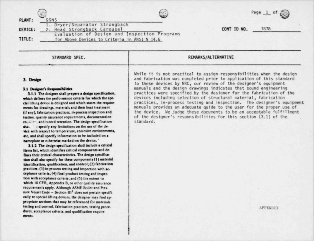
|While it is not practical to assign responsibilities when the design
3. Design and fabrication was completed prior to application of this standardto these devices by NRC, our review of the designer's equipment
3.1 Desipse'a Respaastheities manuals and the design drawings indicates that sound engineering3.1.1 ne designer shall prepare a design specification, practices were specified by the designer for the fabrication of the
which defines the performance criteria for which the spe- devices including selection of structural material, fabricationcial lifiing device is desisned and which states the require- practices, in-process testing and inspection. The designer's equipmentmenti for drawinss. materials and theit heat treatment manuals provides an adequate quide to the user for the proper use of(if any), fabrication practices. in process inspection and the device. We judge these documents to be an acceptable fulfillmenttestine, quality assurance requirements documentation of the designer's responsibilities for this section (3.1) of the .
reyd.t% and record retention. De design specifical on standard.shat ; specify any limitations on the use of the dt-vice with respect to temperature, corrosive environments. -
etc, and shall specify information to be included on a,
nameplate or otherwise marked on the device.'3.1.2 De design specification shallinclude a critical
items list, which identifies critical components and de-,
fines their critical characteristics. De design specifica-tion shall also specify for these components (I) materialidentification, qualification, and control;(2) fabrication
.i practices;(3)in-process testing and inspection with ac-eeptance criteria;(4) final product testing and inspec-tion with acceptance criteria;and (5)the extent towhich 10 CFR Appendix B,or other quality assurancerequirements apply. Although ASME Boiler and Pres-
2sure Vessel Code - Section |11 does not pertain specifi-cally to special lifting devices, the designer may find ap-propriate sections that may be referenced for materialstesting and control, fabrication practices, testing proce. APPENDIXdures, acceptance criteria, and qualification require-ments.
_ _ _ _ _ - - _ _ _ - - _ _ _ . _
)
$ PagaLcfh'PLANT: GNS
1. Dryer / Separator Strongbacki DEVICE: 7. Head strongback Carousel CONT ID NO. 878
-
Evaluation of Design and Inspection Programs for AboveTITLE: Devices to Criteria in ANSI N 14.6
s..
STANDARD SPEC. REMARKS / ALTERNATIVE
3.3.3 The designer shall furnish siped attens analy- Design calculations for the Head Strongback and Dryer / Separatorsen demonstrating the adequacy of the special bfting Strongback have been performed (GE letter MPGE-81/187 dateddevice and its components with respect to any loads September 17,1981).that may be imposed upon them dwing the performanceof their functions. These analyses shall also demonstrate
that appropriate margins of safety have beert,ggvjdgd.3.lA The designer shallindicate what repair proce-
dures are permissible and set criteria for acceptable re. This requirement is applicable only during fabrication.pair procedures and testing.
3.2 Desip Otteria3.2.1 Stress Desip Factoe* All lif ting members are designed with a factor of safety of a
minimum of 5 with respect to the materials ultimate tensile3.2.1.I The load bearing members of s special
lifting device shall be capable oflifting three times the strength and a minimum of 3 with respect to their yield strengths.combined weight of the shipping container with whichit will be used, plus the weight ofintervening compo-ments of the speciallifting device, without generatinga combined shear stress or maximum tensile stress atany point in the device in riess of the correspondingudnimum yield strength of their materials of construc-tion. They shall also be capable oflifting five timesthat weight without exceeding the ultimate strengthof the materials. Some materials have yield strengthsvery close to their ultimate strength. When materialsthat have yield strengths above 80% of their ultimate.
strength are used, each case requires special considers-
| tion, and the foregoing stress desip factors do notapply. Desip shall be on the basis of the material'sfracture toughness, and the desiper shall establish thecriteria.
3.2.1.1 The foregoing stress design factors arenot intended to apply Io situations where high localstresses are tr:leved by slight yleiding in the material.
C e(.j;7 Paga 3 C IS'G: D~
PLANT: GGNS1. Dryer / Separator Strongback 7878 -
DEVICE: ?. Head stronaback Carousel CONT ID ND.
Evaluation of Design and Inspection ProgramsTITLE: fnr Above Devices to Criteria in ANSI N 14.6 N/C=Not Covered
N/A=Not Applicable
STANDARD SPEC. REMARKS / ALTERNATIVE
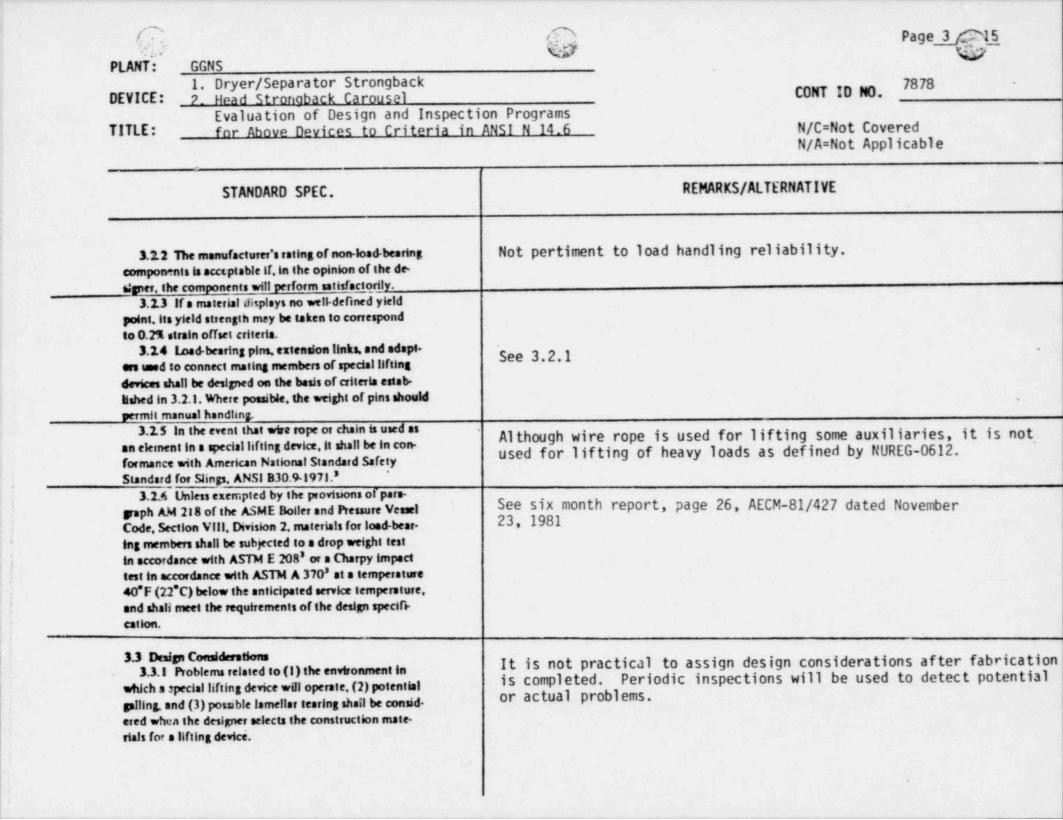
3.12 1he manufacturer'a rsiins of non load bearing Not pertiment to load handling reliability.components is accsptable if,in the opinion of Ihe de-6:per, the components will perform satisfactorily.
3.13 If a material displays no well-defined yieldpoint,its yield strength may be taken to correspondto 0.2% strain offset criteria.
3.14 toed bearing pins, extension links, and adapt. See 3.2.1-
ers used to connect mating members of specialliftingdev6ces shall be designed on the basis of criteria estab-lished in 3.2.1. Where possible, the weight of pins should ,
permit manual handhng.3.15 In the event that wtre rope or chain is used as Although wire rope is used for lifting some auxiliaries, it is not,
an element in a speciallifting device,it shall be in con. used for lif ting of heavy loads as defined by NUREG-0612.formance with American National Standard sefetyStandard for Slings. ANSI B30.91971.8
*
3.2A Unless exempted by the provisions or pare- ,
ymph AM 218 of the ASME Boller and Pressure Vesel See six month report, page 26, AECM-81/427 dated November,'
Code, Section Vill, Division 2. materials for lood beer. 23, 1981.
Ing enembers shall be subjected to a drop weight testin accordance with ASTM E 208' or a Charpy impact
c 8,1 test in accordance with ASTM A 370 at a temperature
40*F (22*C) below the anticipated service tempersture.'
and shall meet the requirements of the desip specifi-*
cetlon.
| 3.3 Desip Consideestions It is not practical to assign design considerations af ter fabricationi 3.3.1 Problema related ro (I) the environment io is completed. Periodic inspections will be used to detect potential| which s special lifting device war operate. (2) potential or actual problems.
piling, and (3) potable lamelist tearing sheil be consid.ered when the desiper selects the construction mate-etals for a lifting device.
.
1
h Page 4PLANT: GGNS
1. Dryer / Separator Strongback -
DEVICE: 2. Head stronaback Carousel CONT ID NO. 7878Evaluation of Design and Inspection Programs
TITLE: for Above Devices to Criteria in ANSI N 14.6 N/C=Not CoveredN/A=Not Applicable
STANDARD SPEC. REMARKS / ALTERNATIVE
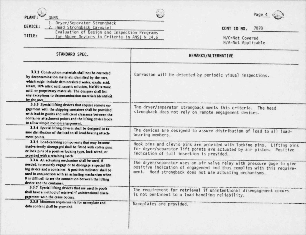
3.3.2 Censtruction materials shali not be corrodedby decontamination materials identified by the user, Corrosion will be detected by periodic visual inspections.which might include demineralized water. oxalic acid,steam. lo% nitric acid. caustic aolution. NaOl+ tartaricacid,or proprietary materials The designer shalllistany esceptions to decontamination materials identificilby Ibtyser.
--
3.3.3 speciallifting devices that require remote en- The dryer / separator strongback meets this criteria. The headgagement with the shipping container shall be providedwith lead in guides and sufficient clearance between the strongback does not rely on remote engagement devices.
.
container attachment points and the lifting device hookto allow simple motion engagement.
3.3.4 speciallifting devices shall be designed io ns- The devices are designed to assure distribution of load to all load-sure distribut}on of the load to allload-bearing attach- bearing members.ment, points.
3.3.5 toad-carrying components that may becomeinadvertently sisengaged shall be fitted with cotter pins.
Hook pins and clevis pins are provided with locking pins. Lifting pins _or lock pins of a positive locking type. lock wired.or for dryer / separator lif t points are actuated by air piston. Positive
indication of full insertion is provided.orovided with a retaininn latch.
+
3.3.6 Ar. actuating mechanism shall be used. lfneeded. to securely engage or to disengage s special lift- The dryer / separator uses an air valve relay with pressure gage to give,
Ing device and a container. A position indicator shall be positive indication of engagement and thus complies with this require-,
.
ment. Head strongback does not use actuating mechanisms.used in conjunction with an actuating mechanism whenit is difficult to see the connection between the Ilftingdevice and the container*
3.3.7 Speciallifting devices that are used in poolsshall have a method of retrievel tf unintentional disen.
The requirement for retrieval if unintentional disengagement occursis not pertinent to a load handling reliability.gagement with the crane occurs.
3.3Dinimum requirements for nameplate and Nameplates are provided.data content shall be provided. .
DEVICE: 2. Head Strongback Carousel CONT ID NO. 7878Evaluation of Design and Inspection Programs
TITLE: for Above Devices to Criteria in ANSI N 14.6 N/C=Not CoveredN/A=Not Applicable
STANDARD SPEC. REMARKS / ALTERNATIVE
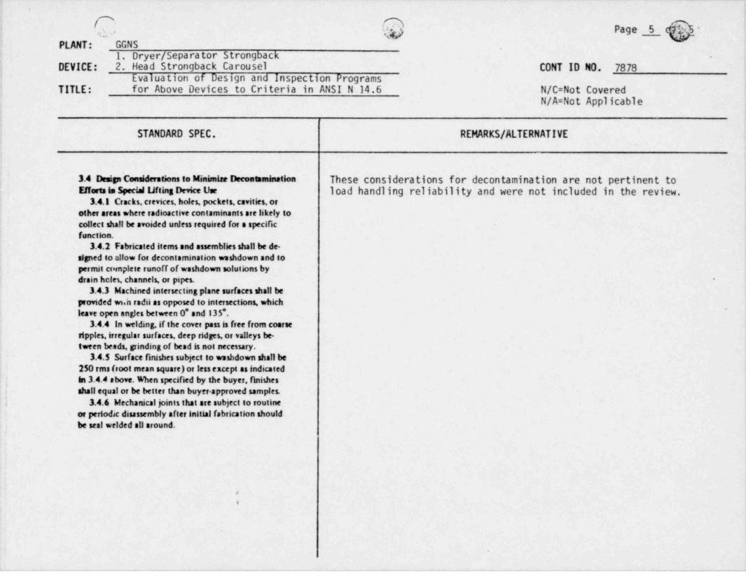
3.4 Desip considerations to Minimise Decontamination These considerations for decontamination are not pertinent toE#erts in Special ufting Device Use load handling reliability and were not included in the review.
3.4.1 Crocks, crevices, holes, pockets, cavities, orother areas where radioactive contaminants are likely tocollect shall be avoided unless required for a specificfunction.
3.4.2 Fabricated items and assemblies shall be de-signed to n!!ow for decontamination washdown and topermit cornplete runoff of washdown solutions bydrain hcles, channels, or pipes. -
3.4.3 Machined intersecting plane surfaces shall beprovided wi,h radii as opposed to intersections, which
~
leave open angles between 0* and 135*.3.4.4 In welding. if the cover pass is free from coarse
ripples, irregular surfaces, deep ridges,or valleys be-tween beads, grinding of bend is not necessary.
3.4.5 Surface finishes subject to washdown shall be250 rms hoot mean square) or less except as indicatedin 3.4.4 above. When specified by the buyer, finishes
;
shall equal or be better than buyer. approved samples.,
i 3.4.6 Mechanical joints that are subject to routineor periodic disassembly after initial fabrication shouldbe seal welded all around.
,
%
!
- _ - - - _ _ _ . - _ _ . _ _ _ _ _ _ _ _ _ - - -
______ _ ______ _ ______ ___ ____ __ _ _
A :O. g , .
U".. V. Pag 2 6 69, y,.PLANT: GGNS
1, Dryer / Separator Strongback .
DEVICE: 2. Head Strongback Carousel CONT ID NO. 7878Evaluation of Design and Inspection Programs
TITLE: for Above Devices to Criteria in ANSI N 14,6 N/C=Not CoveredN/A=Not Applicable
STANDARD SPEC. REMARKS / ALTERNATIVE
These requirements for coatings are not pertinent to load-handling3.5 Contiass reliability and were not included in the review.
3.5.1 Nonferrous metal or alloy steel such as alumi.num, stainless steel, or monel shall not be coated unlessspecified by the buyer.
3.5.2 Nameplates shall not be coated.3.5.3 Carbon steel surfaces subject to decontamina.
tion shau be coated with Phenotine 305, Amercoat 90,or other materials having equivalent properties with re.gard to ease of decontamination, as demonstrated bywritten data (except as indicated in 3.5.9). A thickness '
of IO mus (0.25 mm)is recommended.3.5.4 Prior to blast cleaning. surfaces shall be solvent
cleaned of ou, grease, dirt, salt, and crayon marks. Weld.
splatter shall be removed by grinding.3.5.5 Prior to coating, surfaces shall be blast cleaned
to white metal in accordance with Steel StructuresPainting Council Surface Preparation Specification No.
''5 White 4 fetal Blast Cleaning (SSPC.SPS).* The appear.ance of the surface after cleaning shall correspond toPlctorial Standards of SSPC-VIS 1.*,
3.5.6 Surfaces shall be cleaned of cleaning materialsby vacuuming or blasting with dry, oil. free air.'
3.5.7 Costings shall be mixed, handled, and appliedin strict accordance with the manufacturer's recom-,
mendations.:1
3.5.8 Runs or roughness shall be repaired.3.5.9 Where compatible with buyer.specified decon-'
tamination materials, the designer may specify galva-nir.ing or cadmium, chrome, or nickel plating, with thebuyer's approval. +
3.5.10 Coniact materials (tapes, marking pens, etc)used on materials susceptible to stress corrosion cracking,such as stainless atcel, shall contain less than 250 ppmtotal chloride.
DEVICE: _2. Head stronaback Carousel CONT ID NO. 7 araEvaluation of Design and Inspection Programs
TITLE: for Above Devices to Criteria in ANST N 14.6 N/C=Not Covered ;
N/A=Not Applicable
STANDARD SPEC. REMARKS / ALTERNATIVE
_
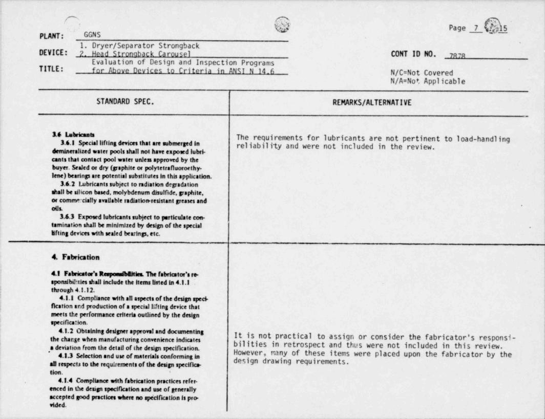
18 l'bricants The requirements for lubricants are not pertinent to load-handling3.6.1 Speciallifting devxes thst are submerged in reliability and were not included in the review.
demineralized water pools shall not have exposed lubri-cants that contact pool water unless approved by thebuyer. Scaled or dry (paphite or polytetrafluoroethy.lene) bearinp are potential substitutes in this application.
3.6.2 f ubricants subject to radiation depadationshall be silicon based, molybdenum disulfide, paphite,or commecia!!y available radiation resistant peases and
.
oils.3.6.3 Exposed lubricants subject to particulate con-
tamination shall be minimized by design of the special -
lifting devices with scaled bearinp. etc.
4. Fabrication
4.I Fabricator'amWhies. The fabricator's te-aponsibil: ties shall include the items listed in 4.1.Ithrough 4.I.12.
4.1.1 Compliance with all aspects of the design speci-
| fication and production of a speciallifting device that'
meets the performance criteria outlined by the designspecification.
4.I.2 0binining designer approvel and documenting-
the change when manufacturing convenience indicates It is not practical to assign or consider the fabricator's responsi-; bilities in retrospect and thus were not included in this review.
e o e*
4 and u of t ri co fo g
all respects to the requirements of the design specifice- g eq em n
tion. '
4.1.4 Compliance with fabrication practices tefer-enced in the design specification and use of generallyaccepted good practices where no spe'cification is pro-vided.
DEVICE: 2. Head Strongback Carousel CONT ID NO. 7878Evaluation of Design and Inspection Programs for
TITLE: Above Devices to Criteria in ANSI N 14.6.,
STANDARD SPEC. REMARKS / ALTERNATIVE
4.1.5 Qualification of welding procedures, welders,and welding operators in accordance with ASME Bollerand Pressure Vessel Code - Section IX, or by AWSStructural Welding Code DI.I.' as required by thedesign spectilcation.
4.1.6 Psovision of a quality assurance plogram nec.ensary to conform to the applicable requirements ofCode offedaalRegulations, Title 10. Par 50, Appen-dix B, which requires the fabricator to organize, plan,establish, document, implement, and maintsin systems ,
using written pocedures. The extent to which 10 CFR50, Appendix B, applies to the speciallifting device in See remarks under 4.1 above.question is defined in the design specification - critical
.
6tems list.
4.1.7 Provision for identification and certificationof snaterials, as required by the design specification andthe critical iterr.s list.
i 4.1.8 Provision for in-process inspection and testing,as required by the design specification, and provision.
| ofinformation that may be required by the inspector'j in the performance of this function.
4.1.9 When the fabricator obtains materials or ser-~
vices for which the design specification imposes require-;
ments, verifiestion that such materials or services a e
produced under the appropriate controls and qualifica-tions and meet requirements of the design specification,or performance of a suitable inspection and testing pro--
pam to determine that they meet those requirements.4.1.10 ProAsion of written procedures for the per--
formance of each step in the fabricalion, machining,testing inspe.: tion, and assembly of the speciallifting -
DEVICE: ?. Head Strongback Carousel CONT ID NO. 7878Evaluation of Design and Inspection Programs
TITLE: for Above Devices to Criteria in ANSI N 14.6 N/C=Not CoveredN/A=Not Applicable
STANDARD SPEC. REMARKS / ALTERNATIVE
,
4.I.II Retention of, or supplying the buyer with, See remarks under 4.I above,documents a; required by purchase agreements verifyiqthe conformance to the design specification and anyreferenced specincations or standards that may be in-cluded in the design specification.This documentationshall also include all pertinent information relative tothe procedures and materials used, the qualification '
of welders, welding operators, testing personnel, andasrbuilt drawings of the devia.
4.I.12 Supplying the owner with certification of *
compliance verifying that all provisions and require-ments of the design specification and the performance -
criteria have been met, and also supplying the owner.
with aufficiem documentation relative to conformanceto satisfy his need for his quality assurance propam.
4.2 Inspector's ResponsibGities. Various inspections It is not practical to consider or assign inspector's responsibilitiesofincoming material. in process work. and finished in retrospect and thus these requirements were not included in the
i product sNallinice pisce aecording to design specih'will be used to identify any deficiencies or defects.review. Inspections for verifying continuing compliance under Section 5'
tions. In each case the purchase speement shall deter-
| mine who performs these inspections. In all cases, theresponsibilities of the inspectors shall be as indicatedin 4.2.1 through 4.2.5.
I 4.2.I The inspector shall famDiariae himself withthe design specification and the specific requirementsthat demand verification by the inspector.
| 4.2.2 Where necessary, the inspector shall becomequalified in the inspection or testing techniques requiredby the duties called for by the design specification, sc.
'
cording to specified standards. .
_ - ___ _ _ _ _ _ _ _ _____ ___
C** idGNS h Page 10 D51
OPLANT: F1. Dryer / Separator Strongback -
.
DEVICE: 2. Head Strongback CarouselCONT ID NO. 7878
tvalua tion ot Uesign ano inspection ProgramsTITLE: for Above Devices to Criteria in ANSI N 14.6 N/C=Not Covered_
N/A=Not Applicable
STANDARD SPEC.- REMARKS / ALTERNATIVE
**4.13 The inspector shall verify by specified tech. *
alques, or suitable techniques if none is specifled, thatthe material oc component meets the requirements setforth by the design specification and shall provide tangi.ble evidence of his approval.
4.14 The inspector shall tog or otherwise idenlifyand isolate any material component or device that failsto conform Io the requirements of the design specifica-tion; this shall be done in such a way as to indicateclearly its deficiency.
*
4.2.5 The inspector shall, where necessary,obtainfrom the fabricator or others the necessary records tosupporI his inspection or testing. .
4.3 Fabrication Considerations In general.the design_ __.
specification will designaie fabrication practices to be It is not practical to address " fabrication considerations" after.
followed or avoided. However, the following parayaphsfabrication is completed. Periodic inspection will be used to identify
(4.3.1 through 4.3.3) list some practices to be followed ,any deficiencies or defects.
for ease of decontamination or conerof of corrosion.4.3.1 Materials that must be marked shall be marked
by any method that will not result in harmful contami-
nation or sharp discontinuities. Stamping,if not pro-hibited by design specification, shall be done by low
,
stress blunt nosed-continuous-dot or blunt. nosed-inter.| rupted-dot die stamps.'
4.3.2 In grinding, cutting.or wire brushing stalnless; steels care shall be taken that tools, wheels,or brushes
are of compatible materials that do not carry foreignmetal, which can become attached to or embedded inthe stainless surface.
4.3.3 In thermal cutting of stainless steel, the use ofiron powder is prohibited in order to prevent dilutionof the stainless composition.
_ - - - _ _ _ - - - _ - .
O. ,Q Page 11 OS -1 1./ %!# G
'
CONT ID NO. 7878PLANT: GGNS.
1.6. Dryer / Separator StrongbackCRANE: 2. Head stronaback Carousel
i Evaluation of Design and Inspection Programs| TITLE: for Above Devices to Criteria in ANSI N 14.6 N/A=Not Applicable|
COVERAGE BY COVERAGE BY REMARKS / JUSTIFICATION FOREXISTING NEW OR REVISED NON COMPLIANCE OR
STANDARD SPEC PROCEDURE PROCEDURE ALTERNATIVE SPEC
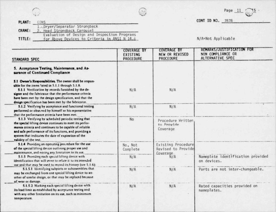
5. AcceptanceTesting, Maintenance,and As-sarance of Continued Compliance
5.1 Ownee's Responsibilities. The owner shall be respon-sible for the items !isted in 5.1.1 through 5.l.8.
5.3.1 Verification by records furnished by the de- N/A N/ACgper and the fabricator that the performance criteriahave been met by the design specification, and that the
design specificatic,n_ has been rnet,by the fabricator. -,
5.1.2 Verifying by acceptance and functional testing N/A N/Apasformed or observed by himself or his representativethat the. performance criteria ba.ve.been met.
.,
*
5.1.3 Verifying by scheduled periodic testing that No Procedure Writtenthe speciallifting device continues to meet its perfor- to.providomance criteria and continues to be capable of reliable Coverageand safe performance of its functions, and providing a
,
system that indicates the date of expiration of thevalidity of the test.
' 5.1.4 Providing an operating procedure for the use No, Not Existing Procedureof the speciallifting desice outlining proper use and Compiete Revised to Providenuintenance.and noting any_ limitation _to its use.
identification that will serve to relate it to its intended on devices.use and that may,,he_used_,to, record its history (see 5.1.6).
5.l.5.1 Identifying subparts or subassemblies that N/A N/A Parts are not inter-changeable.may be exchanged from one special lifting device to an-e,ther of similar design, or that may be replaced becauseef_, wear or damage.
,,
5.1.5.2 Marking esch speciallifting device with N/A N/A Rated capacities provided onits load limit as estabhshed by acceptance testing and namepla tes..
with any other limitation on its use, such as minimum -
tImperature.
;
i ( Page 12
PLANT: GGNS CONT ID NO. 7878
|1.%. Dryer / Separator Strongback
CRANE: 2. Head Strongback Carousel; *
; Evaluation of Design and Inspection Programs| TITLE: for Above Devices to Criteria in ANSI N 14.6!
COVERAGE BY COVERAGE BY REMARKS / JUSTIFICATION FOREXISTING NEW OR REVISED NON COMPLIANCE OR
STANDARD SPEC PROCEDURE PROCEDURE ALTERNATIVE SPEC
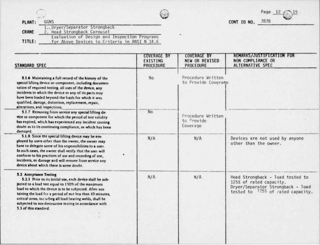
!5.1.6 Maintaining s full record of the history of the No Procedure Written
special lifting device or component, including documen. to Provide Coveracetation of required testing, all uses of the device, anyincidents in which the device or any of its parts mayhave been loaded beyond the loads for which it wasqualified. damage, distortion, replacement, repair,alterations, and inspe_ctions.
5.1.7 Removing frorn service any speciallifting de. Novice or component for which the period of test validity Procedure Writtenhas expired, which has experienced any incident causing to Provide ~
doubt as to its continuing compliance, or which has been Coverdgedamaged. .
5.1.8 Since the speciallifting device may be en"N/A N/A Devices are not used by anyone
ployed by users other than the owner, the owner may other than the owner.have to delegate some of his responsibilities to a user.In such cases, the owner shall verify that the user will
'conform to his practices of use and recording of use, *
incidents, or damage and will remove from service anydevice about which there is some doubt.
5.2 AcceptanceTestingN/A N/A Head Strongback - load tested to5.2.1 Prior to its initial use, eich device shall be sub.
jected to a load test equal to 150%of the maximum 125% of rated capacity.Dryer / Separator Strongback - 1oadload to which the device is to be subjected. After su" tested to 125% of rated capacity.
taining theload for a period of not less than 10 minutes,critical areas, inc:uding all load. bearing welds, shall besubjected to noridntructive testing in accordance with5.5 of this standard.
1.6. Dryer / Separator StrongbackCRANE: 2. Head Stronaback Carousel
Evaluation of Design and Inspection ProgramsTITLE: for Above Devices to Criteria in AfMT N 14 Fi
COVERAGE BY COVERAGE BY REMARK 5/ JUSTIFICATION FOR
EXISTING NEW OR REVISED NON COMPLIANCE OR
STANDARD SPEC PROCEDURE PROCEDURE ALTERNATIVE SPEC
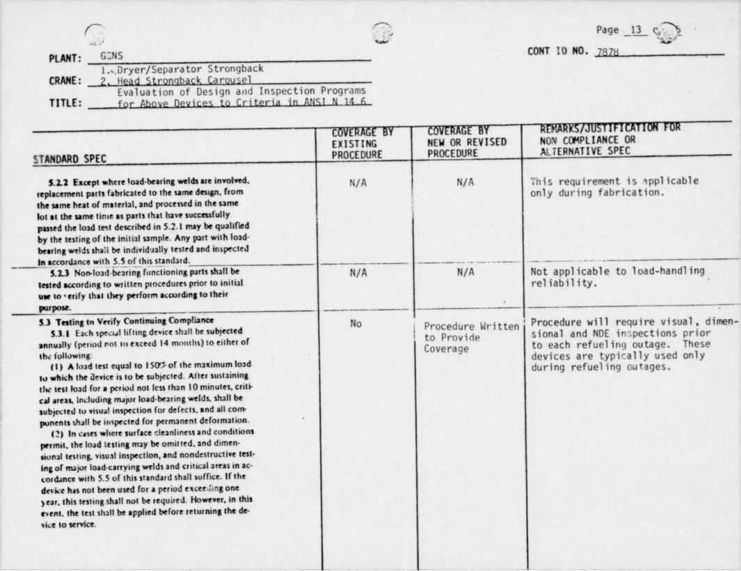
5.2.2 Except where load-bearing welds are involved. N/A N/A This requirement is applicablereplacement parts fabricated to the same design, fromthe same heat of material,and processed in the same
.Only during fabrication,
lot at the same time as parts that have successfully
passed theload test described in 5.2.1 may be qualifiedby the testing of the initial sample. Any part with load-bearing welds shall be individustly tested and inspectedin accordance with 5.5 of this standard. __
5.2.3 Non load bearing functioning parts shall be N/A N/A Not applicable to 1oad-handlingtested according to written procedures prior to initial rellabil ity.
"
use to * erify that they perform according to their.
Purpose. .
5.3 Testing to Verify Continuing Compliance NO Procedure Written ' Procedure will require visual, dimen-5.3.1 Each special lifting device shall be subjected to Provide sional and NDE inspections prior
cEnually (period ont to exceed 14 months) to either of Coverage to each refueling outage. Thesethe following: devices are typically used only.
'
(1) Aload test equal to 150'*rof the maximumload during refueling outages.to which the Device is to be subjected. After sustainingtie test load for a period not less than 10 minutes.criti--
cal areas, including major load-bearin g welds, shall besubjected to visual inspection for defects, and all com-
-
ponenis shall be inspected for permanent deformation.'
(2) In cases where surface e.leanliness and conditionspermit, the load testing may be omitted, and dimen-
,
sional testing, visual inspection, and nondestructive test-lig of major load carrying welds and critical areas in ac.cordance with 5.5 of this standard shall suffice. If thedevice has not been used for a period exceedingone
) ear, this testing shall not be required. However,in thiscent. the test shsil be applied before returning the de-
Evaluation of Design and Inspection ProgramsTITLE: for Above Devices to Criteria in ANST N 14,.6
COVERAGE BY COVERAGE BY REMARK 5/ JUSTIFICATION FOR
EXISTING NEW OR REVISED NON COMPLIANCE OR
PROCEDURE PROCEDURE ALTERNATIVE SPECSTANDARD SPEC
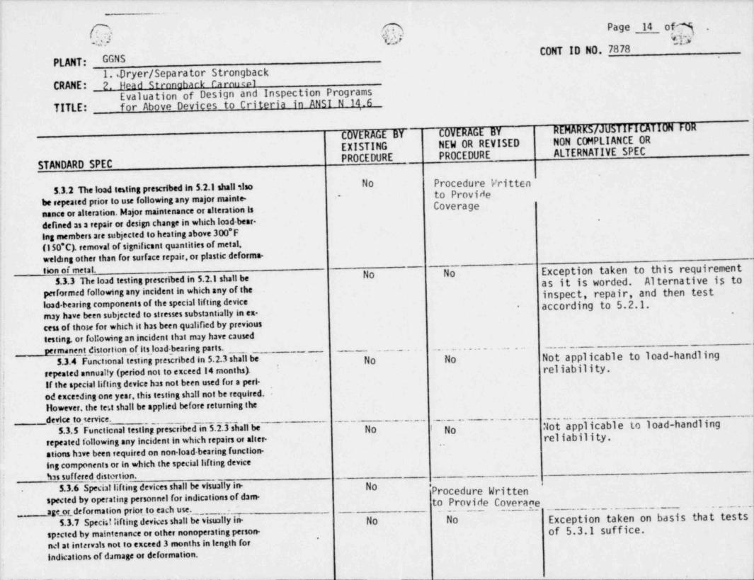
No Procedure Vritten5.3.2 The load testing prescribed in 5.2.1 shall slao to Providebe repeated prior to use following any major mainte- Coverage
-
nance or alteration. Major maintenance or alteration isdefined as a repair or design change in which load-bear-
,
Ing members are subjected to heating above 300*F(150*C). removal of significant quantities of metal,welding other than for surface repair, or plastic deforma-
No No Exception taken to this requirementtion of metal.5.3.3 The load testing prescribed in 5.2.l shall be as it is worded. Alternative is to
performed following any incident in which any of the inspect, repair, and then testload bearing components of the special lifting device according to 5.2.1.-
may have been subjected to stresses substantially in ex. -
cess of those for which it has been qualified by previous
testing. or following an incident that may have causedpermanent distortion of its load-bearing parts. _ _, __ , _ , _ ,
Not applicable to 1oad-handling_
5.3.4 Functional testing prescribed in 5.2.3 shall be No No
repeated annualfy (period not to exceed 14 months). reliability *,
iIf the speciallifting device has not been used fut a peri-?
od exceeding one year, this testing shall not be required.,
However the te.t shall be applied before returning the|. device to service. ~
No Not applicable to load-handling'
I ~5.3'.5' Functional testing prescribed in 5.2.3 shall be No f
repeated following any incident in which repairs or alter- "
rel iabil ity.;
ations have been required on non load bearing function-ing components or in which the special lifting devicehas suffered distortion.
5.3.6 Special lifting devices shall be visually in. No fProcedure Written.
spected by operating personnel for indications of dam. to Provide Coverane~~ ~ ~ " '
age _or deformation prior to each use. ~~ ~
Exception taken on basis that tests~ ~ ' ~
5.3.7 Speciallifting devices shall beiisually in- No No=
spected by ma!ntenance or other nonoperating person- of 5.3.1 s @ ce..
nel at intervals not to exceed 3 months in length forIndications of d.amage or deformation.
.
_ _ - _ - _ - - __-_- - _ - . _ _ __
__
Page 15 , .
2 . ,
'D^CONT ID NO. 7878
PLANT: GGNS1.,, Dryer / Separator Strongback
CRANE: 2. Head Strongback CarouselEvaluation of Design and Inspection Programs
TITLE: for Above Devices to Criteria in ANSI N 14.6
COVERAGE.BY COVERAGE BY REMARK 5/ JUSTIFICATION FOR
EXISTING NEW OR REVISED NON COMPLIANCE OR
STANDARD SPEC PROCEDURE PROCEDURE ALTERNATIVE SPEC
5.3.8 Each speciallifting ded e shall be assed o' No Yesthe record system updated after annual testing.or both, Revisedindicating the empiration date of the validity of that 0.P. 5241test.
5.4 Maintenance and Repelr No Procea.ure nritten..
5.4.1 welding' fabrication. heat treatment. testing. ,- to Provideand inspection procedures and qualifications involved in ,
Coveragerepair or alteratio_ of specist lifting devices shall be innaccordance with the design specification. If no specialrequirert, its for repalt or alteration are provided inthe design specifiestion, these operations shall be gov-erned by the sama requirements applying to the original ,
fabrication.5.4.2 Defective bolts. studs.snd nuts shall be re- No Procedure Written
placed rather than repaired. to Provide Coverage5.5 Nondestructi eTesting Procedures, Personnel
No Procedure Written"
e
Qaalafications, and Acceptance Criteria to Provide5.5.1 Inspections utilaing liquid penetrant or mag, Coverage
netic particle examination shall be performed by writtenprocedures and by personnel, both qualified in accor-d&nce with the rules in the current edition of ASMEBoiler and Pressure Vessel Code, Section V, Articles I,6. 7. 74, and 25.
5.5.2 Uquid penetrant and magnetic particle accep- alo Procedure Written.
tance standards shall be as indicated in paragraphs to Provide CoveraarNF 5350 and NF 5340 of the current edition of ASMEBoiler and Presst.re Vessel Code. Seetion Ill. Division 1.