Instructions for use Title MITIGATION MEASURES FOR EXPANSION JOINT EFFECTS ON SEISMIC PERFORMANCE OF BRIDGE STRUCTURES Author(s) ABDEL RAHEEM, SHEHATA E.; HAYASHIKAWA, T. Citation Proceedings of the Thirteenth East Asia-Pacific Conference on Structural Engineering and Construction (EASEC-13), September 11-13, 2013, Sapporo, Japan, B-1-1., B-1-1 Issue Date 2013-09-11 Doc URL http://hdl.handle.net/2115/54235 Type proceedings Note The Thirteenth East Asia-Pacific Conference on Structural Engineering and Construction (EASEC-13), September 11- 13, 2013, Sapporo, Japan. File Information easec13-B-1-1.pdf Hokkaido University Collection of Scholarly and Academic Papers : HUSCAP
Transcript
Instructions for use
Title MITIGATION MEASURES FOR EXPANSION JOINT EFFECTS ON SEISMIC PERFORMANCE OF BRIDGESTRUCTURES
Author(s) ABDEL RAHEEM, SHEHATA E.; HAYASHIKAWA, T.
Citation Proceedings of the Thirteenth East Asia-Pacific Conference on Structural Engineering and Construction (EASEC-13),September 11-13, 2013, Sapporo, Japan, B-1-1., B-1-1
Issue Date 2013-09-11
Doc URL http://hdl.handle.net/2115/54235
Type proceedings
Note The Thirteenth East Asia-Pacific Conference on Structural Engineering and Construction (EASEC-13), September 11-13, 2013, Sapporo, Japan.
File Information easec13-B-1-1.pdf
Hokkaido University Collection of Scholarly and Academic Papers : HUSCAP
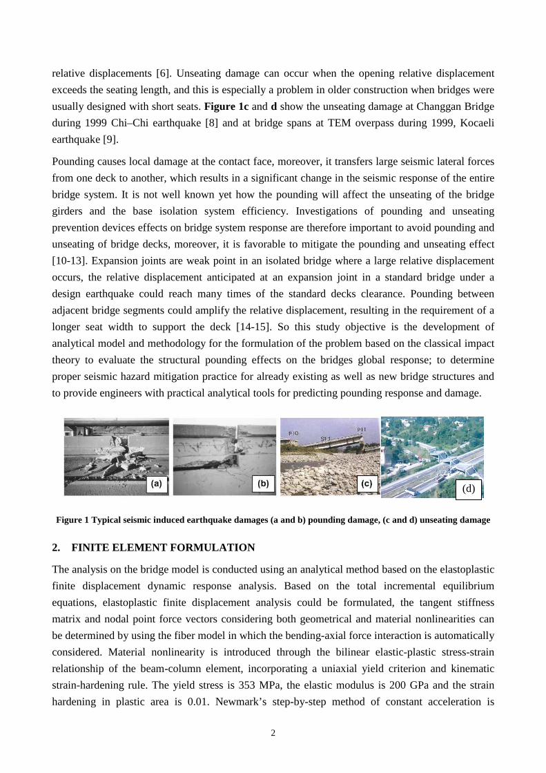
Different configurations of cable restrainers as pounding countermeasures and unseating prevention
system are considered to limit relative displacement at expansion joint, as shown in Figure 3.
Shock absorber of rubber pads between bridge segments and at both ends of restrainers are used to
improve the bridge behavior and reduce the negative effect of sudden impact pulses through smooth
change of impact stiffness and stretching the cable restrainers between adjacent bridge segments.
3.2. Expansion Joint Model
Schematic of bridge expansion joint with various restrainers configuration is shown in Figure 3, an
analytical model of expansion joints that takes account of the effect of pounding and restrainers is
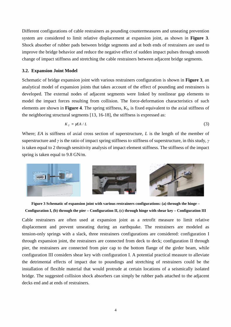
developed. The external nodes of adjacent segments were linked by nonlinear gap elements to
model the impact forces resulting from collision. The force-deformation characteristics of such
elements are shown in Figure 4. The spring stiffness, KI, is fixed equivalent to the axial stiffness of
the neighboring structural segments [13, 16-18], the stiffness is expressed as:
LEAK I /γ= (3)
Where; EA is stiffness of axial cross section of superstructure, L is the length of the member of
superstructure and γ is the ratio of impact spring stiffness to stiffness of superstructure, in this study, γ
is taken equal to 2 through sensitivity analysis of impact element stiffness. The stiffness of the impact
spring is taken equal to 9.8 GN/m.
Figure 3 Schematic of expansion joint with various restrainers configurations: (a) through the hinge –
Configuration I, (b) through the pier – Configurati on II, (c) through hinge with shear key – Configuration III
Cable restrainers are often used at expansion joint as a retrofit measure to limit relative
displacement and prevent unseating during an earthquake. The restrainers are modeled as
tension-only springs with a slack, three restrainers configurations are considered: configuration I
through expansion joint, the restrainers are connected from deck to deck; configuration II through
pier, the restrainers are connected from pier cap to the bottom flange of the girder beam, while
configuration III considers shear key with configuration I. A potential practical measure to alleviate
the detrimental effects of impact due to poundings and stretching of restrainers could be the
installation of flexible material that would protrude at certain locations of a seismically isolated
bridge. The suggested collision shock absorbers can simply be rubber pads attached to the adjacent
decks end and at ends of restrainers.
5
G
C lo s in g
R e l. D isp .
F orce
K I
O p en n in g
S
C lo s in g
R e l. D isp .
F o rce
K r
O p en n in g
C lo s in g
R e l. D isp .
F o rce
K I
O p en n in g C lo s in g
R e l. D isp .
K r
O p en n in g
F orce
i j i j
SG K rK I
Im p a c t E lem en t IE R es tra in e r E lem en t R E
S A D
S A D
(a ) w /o S h ock A b so rb e r D ev ice S A D
(a ) w ith S h o ck A b sorb e r D ev ice S A D Figure 4 Pounding, restrainers and shock absorber device (SAD) analysis models
3.3. Selected Input Earthquake Ground Motions
Owing to severe damage to many bridges caused by the 1995 Hyogo-ken Nanbu Earthquake, very
high ground motion (level II design) is now required in the new Japanese bridge design
specification set in 1996, in addition to the relatively frequent earthquake motion (level I design) by
which old structures were designed and constructed [7, 19-20]. Level II earthquake data has Type I
(inter-plate) and Type II (intra-plate). Three representative ground motions generated by an inland
earthquake at short distance and recorded in the 1995 Kobe earthquake considered in the analysis,
are the standard earthquake motions recommended by Japan Road Association as Level 2; Type II
for moderate soil. In addition to two representative ground motion records are used in the analysis.
4. NUMERICAL RESULTS AND DISCUSSION
The model of a base isolated highway bridge specified according to the Manual for Menshin Design
of Highway Bridges is used to study the influence of pounding on structural response and practical
measures are suggested to mitigate the negative effects of earthquake induced poundings. The finite
element models for nonlinear seismic pounding analysis are built, and the influence of different
parameters on the seismic pounding responses of the bridges is analyzed. Parametric studies are
conducted to determine the effects of frequency ratio, gap size, restrainers’ configuration and
ground motions on the pounding response of the bridge. The isolated bridge model with the
frequency ratio of 0.74 of the two adjacent bridge segments is considered. The fundamental
frequency of the left bridge frame (stiff) and right bridge frame (flexible) with an assumed fixed
base are taken equal to 0.96 and 0.71 Hz, respectively. The LRB bearings are modeled with a
bilinear element with strain hardening. An impact element is used to model pounding between the
6
decks in the bridge; the compression gap element has springs that penalize closing of the gap, the
restrainers are modeled as tension-only springs with a slack. For detailed investigation of the
interaction between adjacent segments of bridge, a wide range of gap size from 0.05 to 0.25 m with
increment of 0.05 m is used to investigate gape size effect on bridge response and compared to
no-pounding case, a critical separation gap (G) of 0.10 m has been selected to study the restrainers
configuration and shock absorber effects. The installation of cable restrainers with clearance length
allows the thermal and shrinkage movement and restrainers are activated when the relative
displacement between adjacent vibrating units exceeds specified clearance length. The clearance
length of a restrainer is initial slack (S) of 0.10 m (configurations I & III) and 0.20 m (configuration
II) to allow relative movement during temperature variations. Five cases are investigated in this
study to determine the different parameters effects:
Case I: The reference case of bridge model response without pounding;
Case II: bridge model with pounding;
Case III: bridge model with pounding and restrainers through hinge (Configuration I)
Case IV: bridge model with pounding and restrainers through pier (Configuration II)
Case V: bridge model with pounding and restrainers through hinge / shear key (Configuration III)
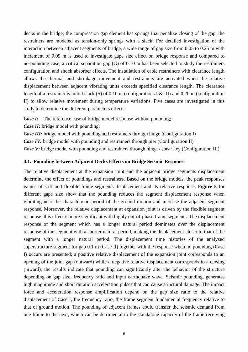
4.1. Pounding between Adjacent Decks Effects on Bridge Seismic Response
The relative displacement at the expansion joint and the adjacent bridge segments displacement
determine the effect of poundings and restrainers. Based on the bridge models, the peak responses
values of stiff and flexible frame segments displacement and its relative response, Figure 5 for
different gape size show that the pounding reduces the segment displacement response when
vibrating near the characteristic period of the ground motion and increase the adjacent segment
response, Moreover, the relative displacement at expansion joint is driven by the flexible segment
response, this effect is more significant with highly out-of-phase frame segments. The displacement
response of the segment which has a longer natural period dominates over the displacement
response of the segment with a shorter natural period, making the displacement closer to that of the
segment with a longer natural period. The displacement time histories of the analyzed
superstructure segment for gap 0.1 m (Case II) together with the response when no pounding (Case
I) occurs are presented; a positive relative displacement of the expansion joint corresponds to an
opening of the joint gap (outward) while a negative relative displacement corresponds to a closing
(inward), the results indicate that pounding can significantly alter the behavior of the structure
depending on gap size, frequency ratio and input earthquake wave. Seismic pounding, generates
high magnitude and short duration acceleration pulses that can cause structural damage. The impact
force and acceleration response amplification depend on the gap size ratio to the relative
displacement of Case I, the frequency ratio, the frame segment fundamental frequency relative to
that of ground motion. The pounding of adjacent frames could transfer the seismic demand from
one frame to the next, which can be detrimental to the standalone capacity of the frame receiving
7
the additional seismic demand. The unbalanced distribution of pounding forces found across the
expansion joint is able to cause local damage to colliding girders and transmit high impact forces to
bearing supports and substructures. The results of different gap size for case II, show that for two
gap size intervals between adjacent superstructure segments, the smallest structural response can be
obtained, the optimal gap size is either a very small one or large enough to avoid collisions. The
interval of a very small gap size stands for the case of nearly fully continuous deck. On the other
hand, in the case of a large gap size, every superstructure segment vibrates independently and the
energy is dissipated through its free movement. Nevertheless, in order to prevent collisions, a
significant increase of the separation gap would be required. However, enlarging the gap between
superstructure segments leads to large expansion joint and disturbs traffic on the deck. At the
pounding instant, the flexible structure will push the stiffer structure away. As a consequence of
this, the flexible structure experiences less vibration, and the stiffer structure suffers stronger
oscillation.
0 0.1 0.2 0.30.3
0.35
0.4
0.45
0.5
Gap (m)
Dis
pl.
(m)
T2-II-1 T2-II-2 T2-II-3
Stiff frame
No
Po
undi
ng
0 0.1 0.2 0.30.4
0.45
0.5
0.55
0.6
Gap (m)
Dis
pl.
(m)
Flexible frame
No
Po
undi
ng
0 0.1 0.2 0.30.2
0.25
0.3
0.35
0.4
0.45
Gap (m)
Rel
. Dis
pl.
(m)
Expansion joint
No
Po
undi
ng
Figure 5 Variation of displacement peak response at expansion joint with gap size
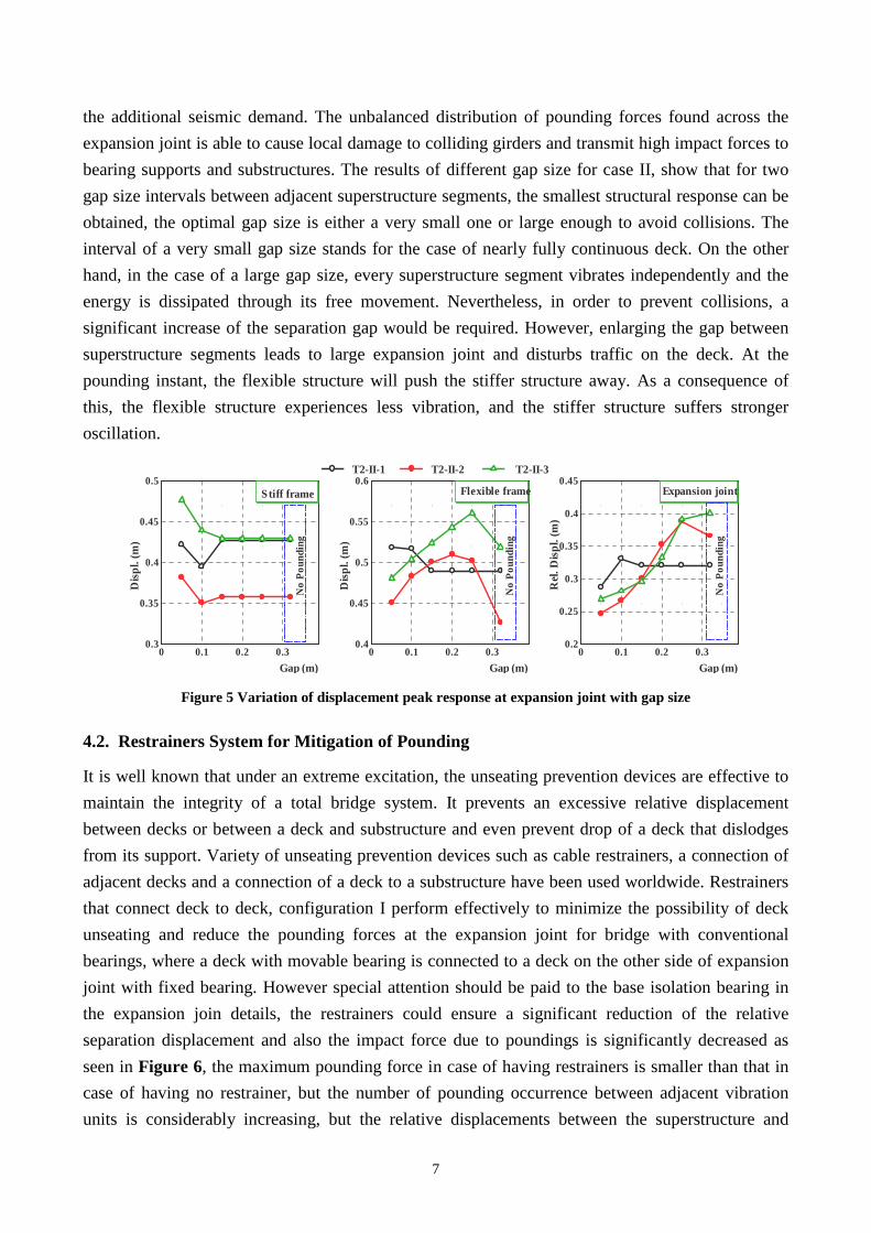
4.2. Restrainers System for Mitigation of Pounding
It is well known that under an extreme excitation, the unseating prevention devices are effective to
maintain the integrity of a total bridge system. It prevents an excessive relative displacement
between decks or between a deck and substructure and even prevent drop of a deck that dislodges
from its support. Variety of unseating prevention devices such as cable restrainers, a connection of
adjacent decks and a connection of a deck to a substructure have been used worldwide. Restrainers
that connect deck to deck, configuration I perform effectively to minimize the possibility of deck
unseating and reduce the pounding forces at the expansion joint for bridge with conventional
bearings, where a deck with movable bearing is connected to a deck on the other side of expansion
joint with fixed bearing. However special attention should be paid to the base isolation bearing in
the expansion join details, the restrainers could ensure a significant reduction of the relative
separation displacement and also the impact force due to poundings is significantly decreased as
seen in Figure 6, the maximum pounding force in case of having restrainers is smaller than that in
case of having no restrainer, but the number of pounding occurrence between adjacent vibration
units is considerably increasing, but the relative displacements between the superstructure and
8
substructure at both left and right LRBs are slightly reduced. Hence configuration I of restrainers is
not effective for unseating prevention for isolated bridges but it could secure falling prevention.
However, restrainers through pier (configuration II) and through hinge with shear key
(configuration III) could effectively restrict the displacements between the superstructure and
substructure, hence reduce the possibility of unseating, moreover the closing and separation relative
displacement is significantly reduced but at the expense of the seismic force demand of the
supporting pier at the expansion joint. The main effect of restrainers upon global bridge motions is
found to constrain and redistribute the relative distances between adjacent vibrations units.
Therefore, it is very important to consider the pounding effect between the adjacent segments in
analyzing the response characteristic of a bridge retrofitted with restrainers.
0 5 10
0
20
40
60 Case II (G= 0.10) Case III (G= 0.10, S= 0.10)
Imp
act f
orce
(M
N)
(i) T2-II-1Time (sec)
0 5 10
(ii) T2-II-2Time (sec)
0 5 10 15
(iii) T2-II-3Time (sec)
Figure 6 Impact force time history at expansion joint
4.3. Shock Absorber for Mitigation of Impact Effects
Since poundings between adjacent decks are unavoidable in an isolated bridge, this effect has to be
carefully included in design. Poundings results in a transfer of large lateral force from a deck to the
other, no matter how the damage of a deck as a direct result of pounding is localized and limited,
this results in damage in piers and bearings in the other deck. Consequently it is effective to provide
a shock absorber between adjacent decks and at the restrainers ends for the mitigation of pounding
effect. The analysis results indicate that reaction forces at the piers bases and pounding forces
exerted on the superstructure can be satisfactorily reduced by applying simple method of placing
rubber shock absorber between bridge segments or at the restrainers’ ends as potential practical
mitigation measures against impact due to poundings and stretching of the restrainers, by that way,
the sudden changes of the stiffness can be smoothed and therefore prevent, to some extent, the
acceleration peaks due to impacts. The effects of a natural rubber shock absorber on isolated bridge
model response are investigated for the studied cases. Figure 7 compares response of the bridge
model with and without the shock absorbers. In the bridge without the shock absorbers, pounding
occurred once resulting in a large impact force; this caused pulse acceleration with high magnitude
spikes at the end of the decks. On the other hand, in the bridge with the shock absorbers, the peak
pounding force is significantly decreased resulting in the decrease of deck acceleration. Installation
of the shock absorbing device significantly reduces the force between the decks generated at
9
expansion joint due to impact and stretching of cable restrainers; hence reduce the acceleration
response spikes. When the expansion joint undergoes an increasing relative movement in the
positive direction, the rubber pad first deforms under compression action providing resistance to the
motion, when the separation relative movement reaches the cable restrainers slack, the restrainers
begin to resist further opening of the joint gap. This resistance builds up nonlinearly with joint
separation with smooth stiffness change. The interaction between the adjacent segments occurs by
both pounding and engagement of the cable restrainers. The installation of a shock absorber could
reduce the required cable restrainers’ force; hence more economical design.
0
20
40
60 w/o SAD with SAD
Case II
Imp
act f
orce
(M
N)
0
20
40
60Case III
Imp
act f
orce
(M
N)
0
20
40
60Case IV
Imp
act f
orce
(M
N)
0 5 10
0
20
40
60Case V
Imp
act f
orce
(M
N)
Time (sec)(i) T2-II-1
0 5 10Time (sec)
(i) T2-II-2
0 5 10 15Time (sec)
(i) T2-II-3
Figure 7 Impact force time history response with/without SAD
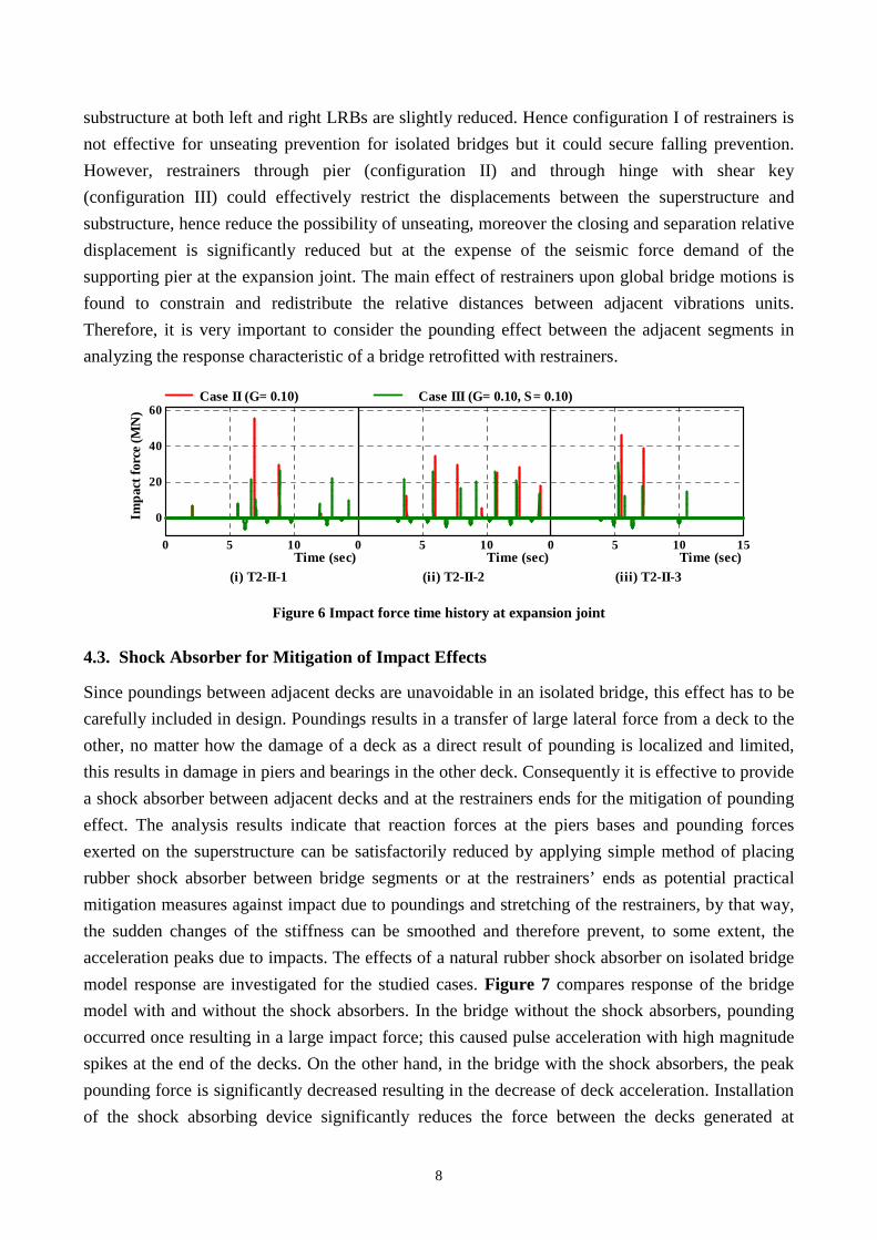
4.4. Rubber Shock Absorber Size Effects on Mitigation Efficiency
The objective of shock absorbers is to mitigate undesirable dynamic effects caused by accidental
impact forces acting on the structure. The investigation of the rubber pad size effects on the impact
force, relative displacement and acceleration responses at expansion joint, show that the responses
are significantly decrease with the increase of rubber sock absorbing device size up to half
gap/slack size, further increase of SAD size slightly enhances the responses as shown in Figure 8,
10
Hence it can be concluded that rubber shock absorbing device with size less half gap/slack size
significantly provides economical and effective design that could reduce the impact force and
acceleration responses. The design concept should maximize acceleration reduction, whilst
minimizing the shock absorber size.
0 20 40 60 80 10010
20
30
40
50
60
SAD Size %
Imp
act f
orce
(M
N)
T2-II-1 T2-II-2 T2-II-3
0 20 40 60 80 100
0.2
0.3
0.4
SAD Size %
Op
enin
g R
el. D
isp
l. (m
)
0 20 40 60 80 1000
50
100
150
SAD Size %
Acc
eler
atio
n m
/s2
Figure 8 Peak responses variation with SAD size
5. CONCLUSIONS
In this study, the effects of poundings on seismically isolated bridges during strong earthquakes are
investigated in an effort to gain insight into this complicated problem, numerical simulation by
nonlinear dynamic response analysis is conducted and pounding mitigation and unseating
prevention for the highway bridges seismic responses are investigated. The finite element models
for nonlinear seismic pounding analysis are built, and the influence of different parameters on the
seismic pounding responses of the highway bridges is analyzed, which include the effects of
frequency ratio, gap size, restrainers’ configuration and slack and input ground motion
characteristics. The simulations results indicate that the effectiveness of seismic isolation could be
significantly affected from potential pounding and unseating prevention measures due to the
interaction between adjacent bridge segments occurred by both impacts and the engagement of the
cable restrainers that tie together adjacent segments. Seismic pounding, generates high magnitude
and short duration acceleration pulses significantly higher than what is typically assumed in design
that can result in severe impact forces that damage structural members like the deck or pier.
Furthermore, seismic pounding can amplify the global response of the participating structural
systems. The influence of pounding on the structural behavior is significant in the longitudinal
direction of the bridge and depends much on the gap size between superstructure segments relative
to the separation displacement of the model without pounding and input excitation characteristics.
The smallest structural response can be obtained for very small gap sizes and for gap sizes large
enough to avoid collisions. However, the application of both intervals is usually an undesirable
solution. The pounding of adjacent frames will transfer the seismic demand from one frame to the
next, which can be detrimental to the stand alone capacity of the frame receiving the additional
seismic demand, so that in situations of potential pounding, neglecting its possible effects leads to
non-conservative design.
11
The unseating prevention devices are effective to maintain the integrity of a total bridge system, it
prevents an excessive relative displacement between decks and even prevent drop of a deck that
dislodges from its support. Configuration I of restrainers connecting deck to deck is not effective for
unseating prevention for isolated bridges but it could secure falling prevention. However, restrainers
through pier (configuration II) and through hinge with shear key (configuration III) could control
the expansion joint opening deformation and secure the unseating of the bridge decks on the
expense of the increase of shear and moment seismic demand of the supporting pier at the
expansion joint, which should be carefully redesign. Restrainers were capable of reducing relative
displacements through expansion joint but unseating prevention capability depends on the
restrainers’ configuration. Further analysis indicates that reaction forces at the piers bases and
pounding forces exerted on the superstructure can be satisfactorily reduced by applying simple
method of placing rubber shock absorber between bridge segments or at the restrainers’ ends. The
sudden changes of the stiffness during poundings can be smoothed through using natural rubber
shock absorber installed at deck ends and/or restrainers end, and therefore prevent, to some extent,
the acceleration peaks due to impacts. Installation of the shock absorbing device significantly
reduces the force between the decks generated at expansion joint due to impact and stretching of
cable restrainers. The rubber shock absorbing device with half gap/slack size provides economical
and effective design that could reduce the impact force and acceleration responses.
REFERENCES
1. Abdel Raheem S. E. (2009). Pounding Mitigation and Unseating Prevention at Expansion Joint of Isolated Multi-Span Bridges. Engineering Structures, 31: 10, 2345-2356.
2. Abdel Raheem, S.E. (2004). Evaluation and prevention of seismic pounding between adjacent building structures. 3rd Egyptian Conference on Earthquake Engineering - EGYQUAKE 3, Cairo, Egypt, 6-8 December 2004, 253-266.
3. Abdel Raheem, S.E. (2006). Seismic pounding between adjacent building structures. Electronic Journal of Structural Engineering - EJSE, The University of Melbourne, 6, 66 -74.
4. Anagnostopoulos, S.A., and Karamaneas, C.E. (2008). Use of collision shear walls to minimize seismic separation and to protect adjacent buildings from collapse due to earthquake-induced pounding. Earthquake Engineering & Structural Dynamics, 37: 12, 1371-88.
5. Kazuhiko Kawashima, Kenji Kosa, Yoshikazu Takahashi, Mitsuyoshi Akiyama, Tsutomu Nishioka, Gakuho Watanabe, Hirohisa Koga, and Hiroshi Matsuzaki. (2011). Damage of Bridges due to the 2011 Great East Japan Earthquake. Proceeding of 43rd Joint Meeting, US-Japan Panel on Wind and Seismic Effects, UJNR, Tsukuba Science City, Japan.
6. Moehle, J.P. (1995). Northridge earthquake of January 17, 1994: Reconnaissance report. Volume 1–Highway bridges and traffic management. Earthquake Spectra, 11 (C), 287–372.
7. Committee of Earthquake Engineering, The 1995 Hyogoken-Nanbu Earthquake, Investigation into Damage to Civil Engineering Structures, Japan Society of Civil Engineers, 1996.
8. Uzarski J, Arnold C, editors. Chi–Chi, Taiwan, earthquake of September 21, 1999 reconnaissance report. CA: Earthquake Engineering Research Institute; 2001.
9. Antony G. Gillies, Donald L. Anderson, Denis Mitchell, Rene Tinawi, Murat Saatcioglu, N. John Gardner and Ahmed Ghoborah. The August 17, 1999, Kocaeli (Turkey) earthquake — lifelines and preparedness, Can. J. Civ. Eng. 28: 881–890 (2001).
12
10. Jankowski, R., Wilde, K., and Fujino, Y. (2000). Reduction of pounding effects in elevated bridges during earthquakes. Earthquake Engineering and Structural Dynamics, 29, 195-212.
11. Desroches, R., and Muthukumar, S. (2002). Effect of pounding and restrainers on seismic response of multiple-frame bridges. ASCE Journal of Structural Engineering, 128: 7, 860-869.
12. Takeno, S., Ohno, H., and Izuno, K. (2004). Velocity-based design of seismic unseating prevention cable and shock absorber for bridges. JSCE Structural Engineering and Earthquake Engineering, 21: 2, 175-188.
13. Zhu, P., Abe, M., and Fujino, Y. (2004). Evaluation of pounding countermeasures and serviceability of elevated bridges during seismic excitation using 3D modeling. Earthquake Engineering and Structural Dynamics, 33, 591-609.
14. Ruangrassamee, A., and Kawashima, K. (2001). Relative displacement response spectra with pounding effect. Earthquake Engineering and Structural Dynamics, 30, 1511–1538.
15. Abdel Raheem, S.E., and Hayashikawa, T. (2003). Parametric study on steel tower seismic response of cable-stayed bridges under great earthquake ground motion. JSCE Structural Engineering and Earthquake Engineering, 20: 1, 25-41.
16. Kawashima, K., and Shoji, G. (2000). Effect of restrainers to mitigate pounding between adjacent decks subjected to a strong ground motion. 12th World Conference on Earthquake Engineering-12WCEE, Auckland, New Zealand, 31 January - 4 February 2000, Paper No. 1435.
17. Abdel Raheem, S.E., and Hayashikawa, T. (2008). Control strategy for seismic pounding mitigation of bridge structures.” International Association for Bridge and Structural Engineering–IABSE, Information and Communication Technology (ICT) for Bridges, Buildings and Construction Practice, Helsinki, Finland, June 4-6, 2008, Paper ID B35.
18. Abdel Raheem, S.E., and Hayashikawa, T. (2008). Innovative Control Strategy for Seismic Pounding Mitigation of Bridge Structures. 14th World Conference on Earthquake Engineering, Beijing, China, October 12-17, 2008, Paper No. 05-02-0107.
19. Japan Road Association, Reference for Highway Bridge Design, Specification for Highway Bridges-Part IV Substructures, 1996.
20. Japan Road Association, Specification for Highway Bridges - Part V Seismic Design, Maruzen, Tokyo, 1996.