Southern Methodist University SMU Scholar Mechanical Engineering Research Mechanical Engineering 9-2012 Mitigation of Pore Generation in Laser Welding of Magnesium Alloy AZ31B in Lap Joint Configuration Masoud Harooni Teaching assistant, [email protected]Fanrong Kong Southern Methodist University, [email protected]Blair Carlson General Motors, [email protected]Radovan Kovacevic Southern Methodist University, [email protected]Follow this and additional works at: hps://scholar.smu.edu/engineering_mechanical_research Part of the Manufacturing Commons is document is brought to you for free and open access by the Mechanical Engineering at SMU Scholar. It has been accepted for inclusion in Mechanical Engineering Research by an authorized administrator of SMU Scholar. For more information, please visit hp://digitalrepository.smu.edu. Recommended Citation Masoud Harooni, Fanrong Kong, Blair Carlson, Radovan Kovacevic, "Mitigation of Pore Generation in Laser Welding of Magnesium Alloy AZ31B in Lap Joint Configuration", ASME-International Mechanical Engineering Congress & Exposition proceedings, 2012, Houston, TX.
Transcript
Southern Methodist UniversitySMU Scholar
Mechanical Engineering Research Mechanical Engineering
9-2012
Mitigation of Pore Generation in Laser Welding ofMagnesium Alloy AZ31B in Lap JointConfigurationMasoud HarooniTeaching assistant, [email protected]
Follow this and additional works at: https://scholar.smu.edu/engineering_mechanical_research
Part of the Manufacturing Commons
This document is brought to you for free and open access by the Mechanical Engineering at SMU Scholar. It has been accepted for inclusion inMechanical Engineering Research by an authorized administrator of SMU Scholar. For more information, please visit http://digitalrepository.smu.edu.
Recommended CitationMasoud Harooni, Fanrong Kong, Blair Carlson, Radovan Kovacevic, "Mitigation of Pore Generation in Laser Welding of MagnesiumAlloy AZ31B in Lap Joint Configuration", ASME-International Mechanical Engineering Congress & Exposition proceedings, 2012,Houston, TX.
Proceedings of the ASME 2012 International Mechanical Engineering Congress & Exposition IMECE2012
November 9-15, 2012, Houston, Texas, USA
IMECE2012-89073
MITIGATION OF PORE GENERATION IN LASER WELDING OF MAGNESIUM ALLOY AZ31B IN LAP JOINT CONFIGURATION
Masoud Harooni RCAM, SMU
Dallas, Texas, USA
Fanrong Kong RCAM, SMU
Dallas, Texas, USA
Blair Carlson General Motors R&D
Warren, MI, USA
Radovan Kovacevic RCAM, SMU
Dallas, Texas, USA
ABSTRACTMagnesium, as the lightest structural metal, has been widely used in the automotive and aerospace industries. Porosity is the main issue in the welding of magnesium alloys and can be caused by surface coatings, hydrogen gas, pre-existing porosity, the collapse of an unstable keyhole and vaporization of alloying elements. In this study, the effect of the oxide layer on pore generation in the welding of AZ31B-H24 magnesium alloy is investigated. A fiber laser with a power of up to 4 kW is used to weld samples in a lap joint configuration. Two groups of samples are studied: as received (AR) surfaces (where an oxide layer remains on the surface) and treated surfaces. The surface treatment includes two techniques: mechanical removal (MR) and the use of a plasma arc (PA) as a preheating source. Also, a separate set of experiments are designed for preheating samples in a furnace in order to investigate whether the pore mitigation effect of a plasma arc is caused by preheating. Observations include a weld bead profile achieved through optical microscopy, chemical compositions tested by Electron Dispersive Spectroscopy (EDS), and mechanical properties measured with a tensile test. The results obtained show that the preheating effect of a plasma arc procedure can effectively mitigate pore generation. The tensile-shear results reveal that PA samples have a higher strength than other groups of samples. KEYWORDSLaser welding, magnesium alloy, oxide layer, lap joint, preheating
save fossil fuel resources. The automotive industry tries to replace heavy metal parts with light weight parts in order to produce economic automobiles that fit society’s needs. US government sources have declared that by using 10% lighter parts, a 7% reduction in fuel consumption would be achieved
[1]. Magnesium is one of the lightest structural metals, a quarter of the weight of steel and a third lighter than aluminum [2]. Magnesium is categorized as green engineering metal since it is light, non-toxic and recyclable [2]. Also, magnesium has the best strength-to-weight ratio among commercial alloys [3]: 122 MPa compared to 103 MPa for aluminum and 45 MPa for low carbon steel [4]. Therefore, magnesium is one of the most promising metals for the production of light weight systems in the twenty-first century [2]. Magnesium alloy production for industry applications increased by 390% in the 12 years from 1995 to 2007 [5].
By realizing that there is a demand for an increase in magnesium alloy production in various industries around the world, especially in the automotive industry, then it becomes equally clear that there is also a need for related fields like assembly and joining to be developed. Today, different joining processes such as arc [6, 7], high energy beams including laser [8-14] and electron beam [15, 16], hybrid techniques [17] and friction stir welding [18] are used for producing magnesium alloys. In fusion joining processes, a large heat input vaporizes low melting alloying elements such as magnesium, aluminum and zinc which results in insufficient weld. This large heat input results in different varieties of welding defects [2]. Therefore, among different welding methods, laser welding has been given more attention because of its low heat input, narrow fusion zone, high depth/width ratio and good weld mechanical properties [2, 12].
One of the main issues in magnesium alloy welding is pore formation in the weld zone [2, 4, 8, 9, 14]. This defect can decrease the mechanical properties of weld joints, especially tensile strength and elongation [9]. The main reasons for porosity formation are coating on the surface [2, 8, 14, 19], pre-existing pores [4, 9], hydrogen pores [20], the collapse of unstable keyholes [21] and alloy elements with low melting points [2].
One of the sources of pore generation is hydrogen. The solubility of hydrogen is higher in molten magnesium than solidified magnesium and this can cause hydrogen porosity in the weld joint. When molten magnesium solidifies, its extra hydrogen is rejected and gas bubbles are formed [2, 4, 19]. Mikucki et al. [20] quantitatively studied the relationship between hydrogen gas and porosity formation in magnesium. They experimentally disclosed an approximate linear relation between hydrogen content and porosity generation and concluded that the hydrogen content should be kept as low as is practically possible.
Pre-existing pores are another type of porosity which is caused by hydrogen. These pores are formed during the manufacturing process of alloys. During the welding process, these existing pores coalesce to form larger pores [4, 9]. Theses pores can be mitigated by choosing suitable process parameters in die-cast magnesium alloys [4, 9]. The formation of pre-existing pores is more likely to occur during the welding process of die-cast magnesium alloys than with sand cast or wrought magnesium alloys [22].
An unstable keyhole is another source for porosity formation during the laser welding process of different alloys [21, 23, 24]. However, the possibility of the formation of these defects is less for magnesium alloys [4, 9]. Pastor et al. [25] reported that although an unstable keyhole is one of the main reasons for porosity formation in aluminum alloys, this is not an important issue in magnesium alloys [9]. Zhao et al. [9] studied keyhole and conduction as two different modes of laser welding of magnesium alloys and reported that no porosity change was shown in either of these two modes. This implies that an unstable keyhole is not the main cause of porosity formation in magnesium alloys. Also, the stability of the keyhole depends on the balance of two forces: surface tension and vapor pressure in the keyhole area [9]. Surface tension works to close the keyhole; however, vapor pressure works to keep it open. Since magnesium has a lower surface tension and a higher vapor pressure than aluminum, magnesium alloy properties form a keyhole that tends to be open and stable [9].
Coating on the surface of magnesium metal sheets is one of the causes of pore formation during the welding process [2, 14, 19]. Magnesium is susceptible to galvanic corrosion [2, 26], so the final product should undergo surface treatment before it is used in industries [27]. There are many different procedures which are used to treat magnesium metal surfaces such as chemical conversion coating, anodizing, organic coating, electroless nickel, gas phase deposition, plasma electrolyte oxidation and spray coating [1, 28]. Also, magnesium is a very active metal and reacts with oxygen to create an oxide layer on its surface; therefore, oxides are one of the main inclusions in the welding of magnesium alloys [2, 8].
AZ31B-H24 is an all-purpose Mg-Al-Zn magnesium alloy [19]. The term H24 is related to a hard-rolling procedure which creates a dark grey oxide layer on metal surfaces [19, 29]. This coating layer on the surface is one of the main reasons for pore generation in weld joints [2, 8, 19, 30]; especially when the
welding joint is in an overlap configuration. This oxide layer absorbs moisture from the air [8, 30-33]. Magnesium oxide is not stable and reacts with water molecules in the atmosphere to form magnesium hydroxide (Mg(OH)2) [34]. Magnesium hydroxide has a low decomposition temperature of around 300 �C, and it is at this point that molecular water is released [35], which causes pore generation. There are different surface preparation approaches used before welding for removing the coating from surfaces, including chemical removing [2], mechanical removing such as sand paper [9, 10, 12], sand blasting [14] and preheating with different sources such as laser [36] and plasma arc [37].
In this study, the effect of the oxide layer on pore generation in laser welding and its remedy is investigated on an AZ31B magnesium alloy. A limited number of studies have been done in this area to the knowledge of the authors. Since most of the studies are on butt joint configurations [3, 10-14], the experiments are designed to study the effect of coating layers on weld quality in lap joint configuration. For this purpose, two groups of samples, as received and treated surfaces are studied. Cross-sectional views, EDS analysis and mechanical properties (tensile-shear) of the welded joints are examined in order to identify the oxide layer effect on the weld joint quality.
EXPERIMENTAL PROCEDURES Based on experiments on AR samples and the observation
of pore generation in weld metal, a series of experiments are designed to study the effect of the oxide layer on pore formation. Therefore, two groups of samples are introduced: as received and treated surfaces. Samples with an existing oxide layer on the surface are called as received (AR). Surface treated samples refer to mechanically removed (MR) and plasma arc preheated (PA) surfaces. For MR samples, the oxide layer on the surface is removed by sand paper. Although removing the coating layer through a mechanical procedure might result in a better quality of weld, especially at the interface, it has two negative effects. First, mechanical removing is a time consuming procedure for industrial use that is not cost-effective. Second, since magnesium alloys are susceptible to galvanic corrosion; removing this coating layer deteriorates the corrosion resistance of the samples. For this reason, a new procedure was introduced by adding a plasma arc to preheat the surface. As Figure 1 shows, the laser beam head and the plasma torch are set in tandem to move at the same speed. The distance between the laser head and the torch is set at 100 mm. Based on a series of plasma arc experiments on the metal surface, parameters of preheating are optimized to create a preheated surface which has the least melted area. The arc and laser parameters are shown in Table 1. Also, in a separate experiment, samples are placed in a furnace to investigate whether the effect of the plasma arc on porosity mitigation is due to preheating. For this purpose, two different temperatures of 150�C and 300�C are selected. Samples remain inside the
furnace for 5 minutes and are then brought out and laser welded.
Figure 1- Laser beam head and plasma torch set up as a
tandem
A 4 kW fiber laser and a KUKA robot, as shown in Figure 1, are used for welding samples. Welding is performed with a focused beam on the top surface of two overlapped metal
sheets. The spot diameter size of the focused laser beam is 0.6 mm. Experimental samples are fixed tight in a fixture to ensure that the same constraint is operative on all the coupons. After setting all the required parameters, a robot is run to preheat and weld the samples. A thermocouple system is used to record the temperature history in the plasma arc preheating process. The thermocouple tip is installed at the bottom surface of the upper sheet exactly under the plasma arc scanning line. The weld surface is protected by a shielding gas. Pure argon, with a flow rate of 60 standard cubic feet per hour (SCFH) in the opposite direction of the scanning speed and an inclination angle of 30 degree to horizontal, is fixed for all experiments. The selection of shielding gas parameters is referenced from the literature [8]. The chemical compositions of the base metal and weld samples are tested with the Scanning Electron Microscope- Energy Dispersive Spectrometer (SEM-EDS) provided by Zeiss-EDAX brands. The AZ31B magnesium alloy chemical composition is shown in Table 2.
Table 1- Table 1-Process parameters of laser welding and plasma arc
Arc Current (A) Voltage (V) Distance off (mm) Electrode diameter (mm) Speed (mm/s)
25 30 1.3 1.6 30
Laser Speed (mm/s) Power (W) 30 800 900 1000 1100
Table 2- Chemical composition of base metal tested by EDS
After welding, samples are prepared for metallographical and mechanical property tests. Two pieces of 12 mm × 10 mm are cut with an abrasive water jet machine from each weld for cross-sectional observation. These parts are chosen from the middle part of the weld line to ensure that the start and end instability effects are eliminated. Then, pieces are mounted and polished through the standard procedure. After completing the polishing procedure, samples are etched by using a 2% nital solution to reveal general weld bead geometry. An optical microscope is applied to study the cross-sections of different groups of samples. These mounted samples are used later to evaluate weld bead chemical composition through EDS analysis. Five standard tensile test samples are cut from each specimen to test the tensile property of each weld joint. The standard sample size is shown in Figure 2.
Figure 2- Dimensions of tensile samples in mm [38]
RESULTS AND DISCUSSIONS
Coating effect on pore formation
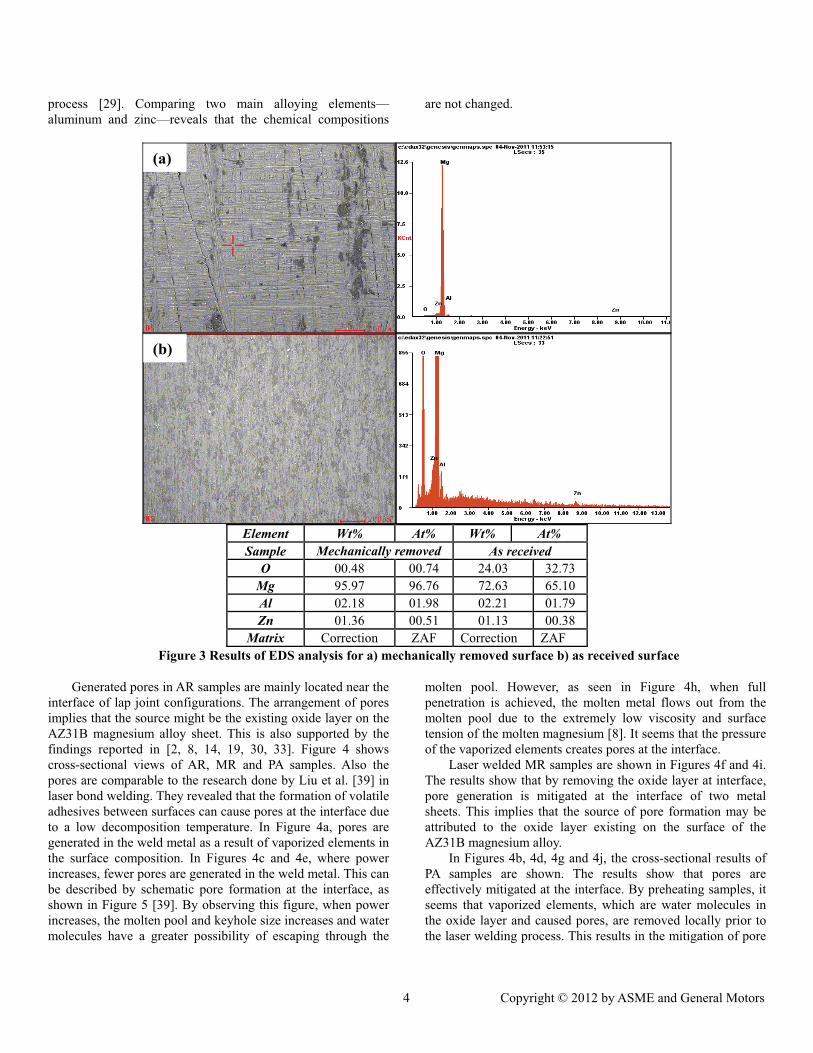
In order to identify the coating layer on a surface, EDS analysis is applied for AR and MR samples. The EDS test results of these groups of samples are shown in Figures 3a and 3b, respectively. When comparing these two figures, it is clear that the oxygen element is obviously decreased on the surface of the MR sample. This implies that the coating layer existing on the AR sample is a dense oxide layer which can be removed through a mechanical procedure. Magnesium starts to oxidize around 450�C [8] and the oxide layer on AZ31B-H24 is the result of the hard-rolling temper during the manufacturing
process [29]. Comparing two main alloying elements—aluminum and zinc—reveals that the chemical compositions
are not changed.
Element Wt% At% Wt% At% Sample Mechanically removed As received
O 00.48 00.74 24.03 32.73 Mg 95.97 96.76 72.63 65.10 Al 02.18 01.98 02.21 01.79 Zn 01.36 00.51 01.13 00.38
Matrix Correction ZAF Correction ZAF Figure 3 Results of EDS analysis for a) mechanically removed surface b) as received surface
Generated pores in AR samples are mainly located near the interface of lap joint configurations. The arrangement of pores implies that the source might be the existing oxide layer on the AZ31B magnesium alloy sheet. This is also supported by the findings reported in [2, 8, 14, 19, 30, 33]. Figure 4 shows cross-sectional views of AR, MR and PA samples. Also the pores are comparable to the research done by Liu et al. [39] in laser bond welding. They revealed that the formation of volatile adhesives between surfaces can cause pores at the interface due to a low decomposition temperature. In Figure 4a, pores are generated in the weld metal as a result of vaporized elements in the surface composition. In Figures 4c and 4e, where power increases, fewer pores are generated in the weld metal. This can be described by schematic pore formation at the interface, as shown in Figure 5 [39]. By observing this figure, when power increases, the molten pool and keyhole size increases and water molecules have a greater possibility of escaping through the
molten pool. However, as seen in Figure 4h, when full penetration is achieved, the molten metal flows out from the molten pool due to the extremely low viscosity and surface tension of the molten magnesium [8]. It seems that the pressure of the vaporized elements creates pores at the interface.
Laser welded MR samples are shown in Figures 4f and 4i. The results show that by removing the oxide layer at interface, pore generation is mitigated at the interface of two metal sheets. This implies that the source of pore formation may be attributed to the oxide layer existing on the surface of the AZ31B magnesium alloy.
In Figures 4b, 4d, 4g and 4j, the cross-sectional results of PA samples are shown. The results show that pores are effectively mitigated at the interface. By preheating samples, it seems that vaporized elements, which are water molecules in the oxide layer and caused pores, are removed locally prior to the laser welding process. This results in the mitigation of pore
generation in the weld bead. In order to better understand the vaporized elements from the oxide layer, pores generated inside weld have been verified by EDS to reveal their chemical composition. Comparative chemical composition is made at a point very close to the pore edge and a point inside the weld metal matrix. In Figures 6a and 6b, EDS analyses results of the pore edge and weld metal matrix are presented, respectively. Results show that oxygen element concentration at the pore edge is increased in comparison with the weld metal chemical composition. This implies that the amount of oxygen inside the pore is higher than the weld metal matrix. As shown earlier in Figure 3, there is a high amount of oxygen on the coating layer of AR samples. However, melting of magnesium oxide might not be the pore source since its melting point is much higher than the magnesium melting point. Two possible reasons are
discussed in what follows. First, the density of magnesium oxide is more than twice that of magnesium. This may be the cause of oxide inclusion in weld metal [8, 30]. Second, magnesium oxide absorbs moisture from air [8, 30-33], and since magnesium oxide is not stable, it reacts with water molecules to form magnesium hydroxide (Mg(OH)2) [8, 34]. Magnesium hydroxide has a low decomposition temperature of around 300 �C and it is at this point that molecular water is released [35]. The released water molecules result in hydrogen pores inside the weld metal in AR samples. In PA samples, preheating is performed to decompose magnesium hydroxide to water molecules. Water molecules are then vaporized prior to laser welding. Therefore, fewer pores are generated in the weld bead.
Figure 4 Cross-sectional view of welds for different pretreatments at welding speed of 30 mm/s
Figure 5 Schematic view of pore formation at interface [39]
Matrix Correction ZAF Correction ZAF Figure 6 EDS analysis of a) pore edge b) weld metal matrix
In order to investigate the temperature between two overlapped sheets, thermocouple is applied at the interface of two sheet metals. Thermocouple is set at the bottom surface of the overlapped sheets concentric with the scanning line of the plasma torch.
Figure 7 Temperature history of the point at the interface of
two lapped magnesium alloy sheets
The temperature history is shown in Figure 7. The results show that the temperature at the interface of overlapped metal sheets reach 300�C. Therefore, magnesium hydroxide reaches its decomposition temperature at the interface. This proves that the plasma arc process can effectively remove the source of pore generation at the interface of two metal sheets.
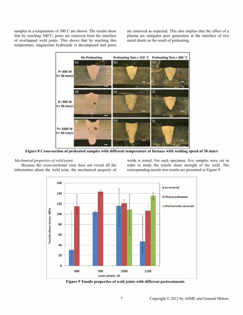
In order to check whether the plasma arc is effective in mitigating the formation of pores, samples are preheated in a furnace prior to welding. In Figure 8, cross-sections of different samples, which are exposed to preheating in the furnace, are shown. In Figures 8a, 8d and 8g, results of weld samples without preheating are shown. The pores are obviously inside the weld bead (the reason for this was discussed earlier). In Figures 8b, 8e and 8h, cross-sectional results of preheated samples of temperatures up to 150�C are shown. Although it seems pores are mitigated, they continue to exist in the weld bead. This shows that preheating up to 150�C does not effectively mitigate the pore generation at the interface of weld joints. In Figures 8c, 8f and 8i, the cross-sections of preheated
samples in a temperature of 300�C are shown. The results show that by reaching 300�C, pores are removed from the interface of overlapped weld joints. This shows that by reaching this temperature, magnesium hydroxide is decomposed and pores
are removed as expected. This also implies that the effect of a plasma arc mitigates pore generation at the interface of two metal sheets as the result of preheating.
Figure 8 Cross-section of preheated samples with different temperature at furnace with welding speed of 30 mm/s
Mechanical properties of weld joints Because the cross-sectional view does not reveal all the
information about the weld joint, the mechanical property of
welds is tested. For each specimen, five samples were cut in order to study the tensile shear strength of the weld. The corresponding tensile test results are presented in Figure 9.
Figure 9 Tensile properties of weld joints with different pretreatments
The average tensile strength of PA samples is higher than AR and MR samples. Results show that by increasing power to 900 W, tensile strength is increased and, when full penetrated depth is achieved, the tensile strength is decreased. As shown in Figure 4, the increase in laser power mitigates pore formation, resulting in higher tensile strength. However, when full penetration is achieved, a molten metal drips out at the bottom sheet and pores are formed in the weld metal, resulting in lower tensile strength. The variation of tensile strength for AR samples is larger than in the case of PA and MR samples, which is related to the instability during the welding of AR samples. However, at P=1000 W, there is variation not only in AR samples, but MR samples as well. The cause of this variation may be attributed to the manual removal of the oxide layer on the surface, which causes different conditions for laser energy absorption. Also, the joining in MR samples that is initiated at this power and penetration to lower sheets is unstable. When the power is increased to 1100 W, the tensile strength in MR samples is higher than in the case of AR and PA samples. This is caused by the difference in the cross-sectional view of the weld bead show in Figures 4h, 4i and 4j. Based on the performed analyses it could be concluded that the best quality of weld is achieved for plasma arc treated surface under 900 W power of laser.
CONCLUSIONSIn this study, laser welding of the AZ31B magnesium alloy
was performed through different welding procedures. The major conclusions of this study are as follows: 1. In overlap joint configuration, pores were mainly formed at
the interface of two sheets as a result of presence of an oxide layer on the surface of AZ31B at once when the oxide layer is removed from the surface, sound weld quality can be achieved.
2. By applying a plasma arc torch as a preheating source in front of a laser welding head, sound weld quality was achieved and pores at the interface were mitigated.
3. By preheating samples inside a furnace up to 300�C, pores were eliminated at the interface during laser welding which implies that the main contribution of the plasma arc as a preheating source is in the elimination of the hydrogen along the joint line.
ACKNOWLEDGEMENTSThis work was funded by the NSF Grant No. IIP-1034652.
The authors acknowledge Andrew Socha, a research engineer at the Research Center for Advanced Manufacturing, for his assistance in performing the experiments.
REFERENCES[1] S. Shrestha, “Magnesium and surface engineering”
Surface Engineering, 2010, pp. 313-316. [2] L. Liming, “Welding and joining of magnesium
alloys” Cambridge, Woodhead Publishing, 2010.
[3] K. Abderrazak, W. B. Salem, H. Mhiri, P. Bournot and M. Autric, “Nd:YAG laser welding of AZ91 magnesium alloy for aerospace industry”, 2009, Metallurgical and Materials Transactions B, Vol. 40, pp. 54-61.
[4] M. Pastor, H. Zhao and T. DebRoy, “Continuous wave-Nd: yttrium-aluminum-garnet laser welding of AM60B magnesium alloy”, 2000, Journal of Laser Applications, pp. 91-100.
[5] A.E.W. Jafros, K.U. Kainer, M.J. Tan and J. Yong, “Recent developments in the manufacturing of components from aluminum-,magnesium- and titanium-based alloys”, 2009, COSMOS, Vol. 5, pp. 23-58.
[6] J. Shena, G. Youa, S. Longa, F. Panb, “Abnormal macropore formation during double-sided gas tungsten arc welding of magnesium AZ91D alloy” 2008, Materials Characterization, Vol. 59, pp. 1059-1065.
[7] D. Min, J. Shen, S. Lai and J. Chen. “Effect of heat input on the microstructure and mechanicalproperties of tungsten inert gas arc butt-welded AZ61 magnesium alloy plates”, 2009, MaterialsCharacterization, Vol. 60, pp. 1583-1590.
[8] X. Cao, M. Jahazi, J.P. Immarigeon and W. Wallasce, “A review of laser welding techniques for magnesium alloys”, 2006, Journal of Materials Processing Technology, Vol. 171, pp. 188-204.
[9] H. Zhao and T. DebRoy, “Pore formation during laser beam welding of die-cast magnesium alloy AM60B-Mechanism and remedy”, 2001, Welding Journal, Vol. 80, pp. 204S-210S.
[10]S.M. Chowdhury, D.L. Chen, S.D. Bhole, E. Powidajko, D.C. Weckman and Y. Zho, “Microstructure and Mechanical Properties of Fiber-Laser-Welded and Diode-Laser-Welded AZ31 Magnesium Alloy”, 2011, Metallurgical and Materials Transactions A, Vol. 42, pp. 1974-1989.
[11]L.D. Scintilla, L. Tricarico, M. Brandizzi and A.A. Satriano, “Nd:YAG laser weldability and mechanical properties of AZ31 magnesium alloy butt joints”, 2010, Journal of Materials Processing Technology, Vol. 210, pp. 2206-2214.
[12]Z. Wang, M. Gao, H. Tang and X. Zeng, “Characterization of AZ31B wrought magnesium alloy joints welded by high power fiber laser”, 2011, Journal of Materials Characterization, Vol. 62, pp. 943-951.
[13]K.H. Leong, G. Kornecki, P.G. Sanders and J.S. Keske, “Laser beam welding of AZ31B-H24 magnesium alloy”, Proceedings of ICALEO, 2008, Orlando USA.
[14] J. Zhu, L. Li and Z. Liu, “CO2 and diode laser welding of AZ31 magnesium alloy”, 2005, Journal of Applied Surface Science, Vol. 247, pp. 300-306.
[15]C.T. Chi, C.G. Chao, T.F. Liu and C.H. Lee, “Aluminum element effect for electron beam welding
of similar and dissimilar magnesium-aluminum-zinc alloys”, 2007, Journal of Scripta Materialia, Vol. 56, pp. 733-736.
[16]S.F. Su, J.C. Huang, H.K. Lin and N.J. Ho, “Electron-beam welding behavior in Mg-Al-based alloys”, 2002, Journal of Metallurgical and Materials Transactions A, Vol. 33, pp. 1461-1473.
[17]L. Liu, G. Song, G. Liang and J. Wang, “Pore formation during hybrid laser-tungsten inert gas arc welding of magnesium alloy AZ31B-mechanism and remedy”, 2005, Journal of Materials science and Engineering A, Vol. 390, pp. 76-80.
[18] J.A. Esparza, W.C. Davis, E.A. Trillo and L.E. Murr, “Friction-stir welding of magnesium alloy AZ31B”, 2009, Journal of Materials Science Letters, Vol. 21, pp. 917-920.
[19]M.M. Avedesian and H. Baker, “Magnesium and magnesium alloys” ASM International Handbook, 1999.
[20]B.A. Mikucki and J.D. Shearouse, “Interdependence of hydrogen and microprosity in magnesium alloy AZ91”, Proceedings of Magnesium Properties and Applications for Automobile, 1993, Detroit, USA.
[21]A. Matsunawa, J.D. Kim, N. Seto, M. Mizutani and S. Katayama, “Dynamic of keyhole and molten pool in laser welding” 1998, Journal of Laser Applications, Vol. 10, pp. 247-254.
[22]A. Weisheit, R. Galun and B.L. Mordike, “CO2 laser beam welding of magnesium-based alloys”, 1998, Welding Journal, Vol. 77, pp. 149s-154s.
[23]A. Matsunawa, J.D. Kim and S. Katayama, “Porosity formation in laser welding-Mechanisms and suppression methods” Proceedings of ICALEO, 1998, San Diego, USA.
[24]A. Matsunawa, “Defects formation mechanisms in laser welding and their suppression methods”, Proceedings of ICALEO, 1994, Orlando, USA.
[25]M. Pastor, H. Zhao, R.P. Martukanitz and T. DebROY, “Porosity, underfill and magnesium loss during continuous wave Nd:YAG laser welding of thin plates of aluminum alloys 5182 and 5754”, 1999, Welding Journal, Vol. 78, pp. 207s-216s.
[26]E. Ghali, W. Dietzel and K.U. Kainer, “General and localized corrosion of magnesium alloys: A critical review”, 2003, Journal of Materials Engineering and Performance, Vol. 13, pp. 7-23.
[27]F.H. Fores and C.M. Ward-Close, “Processing of light metals for enhanced performance” 1995, Journal of Materials Processing Technology, Vol. 48, pp. 667-673.
[28]H. Jin, X. Yang and M. Wang, “Chemical conversion coating on AZ31B magnesium alloy and its corrosion tendency”, 2009, Acta Metallurgica Sinica, Vol. 22, pp. 65-70.
[29]E.J.M. Powidajko, “Weldability of AZ31B magnesium sheets by laser welding processes”, PhD Thesis, 2009, University of Waterloo, Canada.
[30] J. Wegrzyna, M. Mazurb, A. Szyma�skib and B. Balcerowskab, “Development of a filler for welding magnesium alloy GA8”, 1987, Welding International, Vol. 1, pp. 146-150.
[31]S. Otsuki, S. Fukuzawa, “Organic electroluminescent device and method for fabricating same”, Patent, 6737176, USA, May 18, 2004.
[32]S. Wakelin, “System and method for getting gas-phase contaminants within a sealed enclosure”, Patent, 7160368 USA, January 9, 2007.
[33]M. Marya and G.R. Edwards, “The laser welding of magnesium alloy AZ91”, 2000, Welding in the world, Vol. 44, pp. 31-37.
[34]V. Fournier, P. Marcus and I. Olefjord, “Oxidation of magnesium”, 2002, Surface and Interface Analysis, Vol. 34, pp. 494-497.
[35] I. Halikia, P. Neou-Syngouna and D. Kolitsa, “Isothermal kinetic analysis of the thermal decomposition of magnesium hydroxide using thermogravimetric data”, 1998, Thermochimica Acta, Vol. 320, pp. 75-88.
[36]A. Haboudou, P. Peyre, A.B. Vannes, G. Peix, “Reduction of porosity content generated during Nd:YAG laser welding of A356 and AA5083 aluminum alloys”, 2003, Journal of Materials Science and Engineering A, Vol. 363, pp. 40-52.
[37]R. Kovacevic and S. Yang, “Laser welding of galvanized DP980 steel assisted by the GTAW preheating in a gap-free lap joint configuration”, 2009, Journal of Laser Applications, Vol. 21, pp. 139-148.
[38]Annual Book of ASTM Standards, “Nonferrous Metal Products-Aluminum and Magnesium Alloys”, 2001 .
[39]L.M. Liu, D.X. Ren, “Effect of adhesive on molten pool structure and penetration in laser weld bonding of magnesium alloy, 2010, Optics and Lasers in Engineering, Vol. 48, pp. 882-887.