International Journal of Engineering Research and Applications (IJERA) ISSN: 2248-9622 National Conference on Emerging Trends in Engineering & Technology (VNCET-30 Mar’12) Vidyavardhini’s College of Engineering and Technology, Vasai Page 349 MITIGATION OF VOLTAGE SAG IN A DFIG BASED WIND TURBINE USING DVR M Venmathi*, Soumyadeep Chakraborti 1 , Soham Ghosh 2 , Abhirup Ray 3 , Vidhya Nikam 4 * (Senior Lecturer, Dept. of Electrical and Electronics, Dr M.G.R. University, Chennai, Email: [email protected]) 1 (UG Students, Dept. of Electrical and Electronics, Dr M.G.R. University, Chennai, Email: [email protected]) 2 (UG Students, Dept. of Electrical and Electronics, Dr M.G.R. University, Chennai, Email: [email protected]) 3 (UG Students, Dept. of Electrical and Electronics, Dr M.G.R. University, Chennai, Email: [email protected]) 4 (UG Students, Dept. of Electrical and Electronics, Dr M.G.R. University, Chennai, Email: [email protected]) Keywords: DFIG, Voltage Sag, DVR, IGBT based PWM autotransformer, DQO converter, harmonic filters. Abstract Energy is one of the most prominent factors in shaping the civilization of today. Under consideration for non- conventional energy source wind energy has turned out to be a leading source of energy. In recent years there has been a significant global commitment to develop a clean and economical alternative sustainable power source especially from wind. In this field of development wound rotor induction generator has seen considerable success. One scheme of wound rotor induction generator is realised when a converter cascade is used between the slip rings terminals and the utility grid to control the rotor power. This configuration is called Doubly Fed Induction Generator (DFIG). In this paper various aspects of a DFIG system is analysed. It also primarily analyses the voltage sag in a grid connected to a DFIG. The paper implements Dynamic Voltage Restorer as a control technique to mitigate the voltage sag generated due to a fault. Finally the paper concludes with an inference of the voltage profile generated by a DFIG and a vivid study of various parameters at varied conditions. 1. INTRODUCTION Recent growth in industries and energy demand has resulted in a search for non-conventional energy resources. Wind power seems to be a promising alternative with India having a capacity to generate 20,000 MW of power from wind. Wind power projects of aggregate capacity of 8 MW including 7 major wind farm projects of capacity 6.85 MW have been established in different parts of the country. Wind turbines with Doubly Fed Induction Generator (DFIG) as a voltage source has gained attention due to its construction and control ability. Advantages of using DFIG in wind farms lie in the fact that it has a low cut in speed of 15-20 km/hr, a wide range of control and ability to remain connected to grid even in fault conditions. This paper presents an in-depth analysis of different faults in a DFIG based grid and mitigation of the same using a Dynamic Voltage Restorer (DVR). 1.1 DOUBLY FED INDUCTION GENERATOR The working of DFIG is based on the principle of induction generator. It has multiphase wound rotor and a multiphase slip ring assembly with brushes for accessing rotor winding. The rotor windings are connected to the grid via slip rings and a back to back voltage source converter that controls both the rotor and grid currents (hence acting as a control system). By adjusting the converter‟s parameters it is possible to control the active and reactive power fed to the grid independently of the generators turning speed, giving it a distinct advantage over other conventional power generators. Fig.1 shows a schematic representation of a DFIG setup : Fig 1.DFIG model 1.2 VOLTAGE SAG A voltage sag as defined by IEEE Standards 1159- 1995,is a decrease in the RMS voltage at the power frequency for duration from .5 cycles to 1 minute. The measurement of the voltage sag is defined as the percentage of the nominal voltage. Example: Voltage sag to 60% is equal to 60% of nominal voltage i.e. 288 volt for a 480 volt system.
Transcript
International Journal of Engineering Research and Applications (IJERA) ISSN: 2248-9622 National Conference on Emerging Trends in Engineering & Technology (VNCET-30 Mar’12)
Vidyavardhini’s College of Engineering and Technology, Vasai Page 349
MITIGATION OF VOLTAGE SAG IN A DFIG BASED WIND TURBINE USING DVR
M Venmathi*, Soumyadeep Chakraborti1, Soham Ghosh
2, Abhirup Ray
3, Vidhya Nikam
4
* (Senior Lecturer, Dept. of Electrical and Electronics, Dr M.G.R. University, Chennai, Email: [email protected]) 1 (UG Students, Dept. of Electrical and Electronics, Dr M.G.R. University, Chennai, Email: [email protected])
2 (UG Students, Dept. of Electrical and Electronics, Dr M.G.R. University, Chennai, Email: [email protected])
3 (UG Students, Dept. of Electrical and Electronics, Dr M.G.R. University, Chennai, Email: [email protected])
4(UG Students, Dept. of Electrical and Electronics, Dr M.G.R. University, Chennai, Email: [email protected])
shaping the civilization of today. Under consideration for
non- conventional energy source wind energy has turned
out to be a leading source of energy. In recent years there
has been a significant global commitment to develop a clean
and economical alternative sustainable power source
especially from wind. In this field of development wound
rotor induction generator has seen considerable success.
One scheme of wound rotor induction generator is realised
when a converter cascade is used between the slip rings
terminals and the utility grid to control the rotor power. This
configuration is called Doubly Fed Induction Generator
(DFIG). In this paper various aspects of a DFIG system is
analysed. It also primarily analyses the voltage sag in a grid
connected to a DFIG. The paper implements Dynamic
Voltage Restorer as a control technique to mitigate the
voltage sag generated due to a fault. Finally the paper
concludes with an inference of the voltage profile generated
by a DFIG and a vivid study of various parameters at varied
conditions.
1. INTRODUCTION
Recent growth in industries and energy demand has resulted
in a search for non-conventional energy resources. Wind
power seems to be a promising alternative with India having a
capacity to generate 20,000 MW of power from wind. Wind
power projects of aggregate capacity of 8 MW including 7
major wind farm projects of capacity 6.85 MW have been
established in different parts of the country. Wind turbines
with Doubly Fed Induction Generator (DFIG) as a voltage
source has gained attention due to its construction and control
ability. Advantages of using DFIG in wind farms lie in the
fact that it has a low cut in speed of 15-20 km/hr, a wide
range of control and ability to remain connected to grid even
in fault conditions. This paper presents an in-depth analysis of
different faults in a DFIG based grid and mitigation of the
same using a Dynamic Voltage Restorer (DVR).
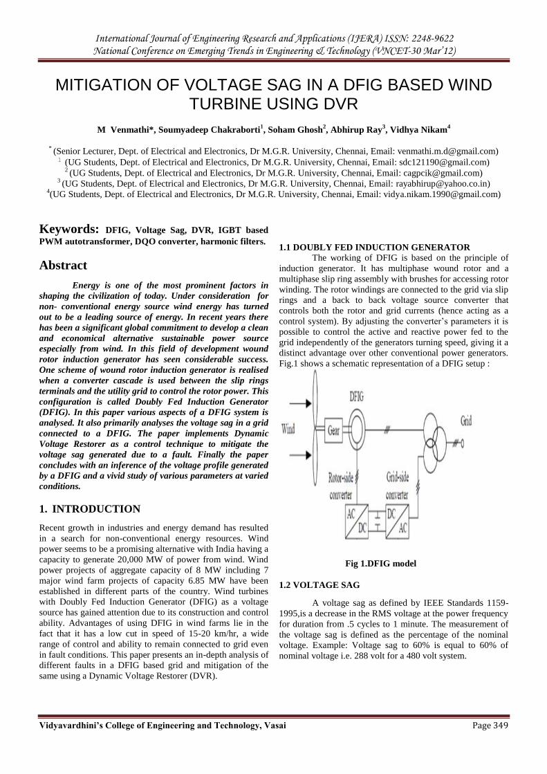
1.1 DOUBLY FED INDUCTION GENERATOR The working of DFIG is based on the principle of
induction generator. It has multiphase wound rotor and a
multiphase slip ring assembly with brushes for accessing rotor
winding. The rotor windings are connected to the grid via slip
rings and a back to back voltage source converter that
controls both the rotor and grid currents (hence acting as a
control system). By adjusting the converter‟s parameters it is
possible to control the active and reactive power fed to the
grid independently of the generators turning speed, giving it a
distinct advantage over other conventional power generators.
Fig.1 shows a schematic representation of a DFIG setup :
Fig 1.DFIG model
1.2 VOLTAGE SAG
A voltage sag as defined by IEEE Standards 1159-
1995,is a decrease in the RMS voltage at the power frequency
for duration from .5 cycles to 1 minute. The measurement of
the voltage sag is defined as the percentage of the nominal
voltage. Example: Voltage sag to 60% is equal to 60% of
nominal voltage i.e. 288 volt for a 480 volt system.
International Journal of Engineering Research and Applications (IJERA) ISSN: 2248-9622 National Conference on Emerging Trends in Engineering & Technology (VNCET-30 Mar’12)
Vidyavardhini’s College of Engineering and Technology, Vasai Page 350
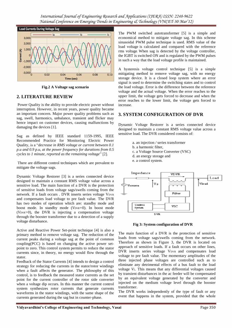
Fig.2 A Voltage sag scenario
2. LITERATURE REVIEW
Power Quality is the ability to provide electric power without
interruption. However, in recent years, power quality became
an important concern. Major power quality problems such as
sag, swell, harmonics, unbalance, transient and flicker may
hence impact on customer devices, causing malfunctions by
damaging the devices [1].
Sag as defined by IEEE standard 1159-1995, IEEE
Recommended Practice for Monitoring Electric Power
Quality, is a “decrease in RMS voltage or current between 0.1
p.u and 0.9 p.u, at the power frequency for durations from 0.5
cycles to 1 minute, reported as the remaining voltage” [2].
There are different control techniques which are prevalent to
mitigate the voltage sags.
Dynamic Voltage Restorer [3] is a series connected device
designed to maintain a constant RMS voltage value across a
sensitive load. The main function of a DVR is the protection
of sensitive loads from voltage sags/swells coming from the
network. If a fault occurs . DVR inserts series voltage VDVR
and compensates load voltage to pre fault value. The DVR
has two modes of operation which are: standby mode and
boost mode. In standby mode (VDVR=0). In boost mode
(VDVR>0), the DVR is injecting a compensation voltage
through the booster transformer due to a detection of a supply
voltage disturbance.
Active and Reactive Power Set-point technique [4] is also a
primary method to remove voltage sag. The reduction of the
current peaks during a voltage sag at the point of common
coupling(PCC) is based on changing the active power set-
point to zero. This control system permits to reduce the stator
currents since, in theory, no energy would flow through the
stator.
Feedback of the Stator Currents [4] intends to design a control
strategy for reducing the currents in the stator/rotor windings
when a fault affects the generator. The philosophy of this
control, is to feedback the measured stator currents as the set
point for the current controller of the rotor side converter
when a voltage dip occurs. In this manner the current control
system synthesizes rotor currents that generate currents
waveforms in the stator windings, with the same shape of the
currents generated during the sag but in counter-phase.
The PWM switched autotransformer [5] is a simple and
economical method to mitigate voltage sag. In this scheme
sinusoidal PWM pulse technique is used. RMS value of the
load voltage is calculated and compared with the reference
rms voltage. When sag is detected by the voltage controller,
the IGBT is switched ON and is regulated by the PWM pulses
in such a way that the load voltage profile is maintained.
A hysteresis voltage control technique [5] is a simple
mitigating method to remove voltage sag, with no energy
storage device. It is a closed loop system where an error
signal is used to determine the switching states and to control
the load voltage. Error is the difference between the reference
voltage and the actual voltage. When the error reaches to the
upper limit, the voltage gets forced to decrease and when the
error reaches to the lower limit, the voltage gets forced to
increase.
3. SYSTEM CONFIGURATION OF DVR
Dynamic Voltage Restorer is a series connected device
designed to maintain a constant RMS voltage value across a
sensitive load. The DVR considered consists of:
a. an injection / series transformer
b. a harmonic filter,
c. a Voltage Source Converter (VSC)
d. an energy storage and
e. a control system.
Fig 3: System configuration of DVR
The main function of a DVR is the protection of sensitive
loads from voltage sags/swells coming from the network.
Therefore as shown in Figure 3, the DVR is located on
approach of sensitive loads. If a fault occurs on other lines,
DVR inserts series voltage VDVR and compensates load
voltage to pre fault value. The momentary amplitudes of the
three injected phase voltages are controlled such as to
eliminate any detrimental effects of a bus fault to the load
voltage VL. This means that any differential voltages caused
by transient disturbances in the ac feeder will be compensated
by an equivalent voltage generated by the converter and
injected on the medium voltage level through the booster
transformer.
The DVR works independently of the type of fault or any
event that happens in the system, provided that the whole
International Journal of Engineering Research and Applications (IJERA) ISSN: 2248-9622 National Conference on Emerging Trends in Engineering & Technology (VNCET-30 Mar’12)
Vidyavardhini’s College of Engineering and Technology, Vasai Page 351
system remains connected to the supply grid, i.e. the line
breaker does not trip. The DVR has two modes of operation
which are: standby mode and boost mode. In standby mode
(VDVR=0), the booster transformer‟s low voltage winding is
shorted through the converter. No switching of
semiconductors occurs in this mode of operation, because the
individual converter legs are triggered such as to establish a
short-circuit path for the transformer connection.
Therefore, only the comparatively low conduction losses of
the semiconductors in this current loop contribute to the
losses. The DVR will be most of the time in this mode. In
boost mode (VDVR>0), the DVR is injecting a compensation
voltage through the booster transformer due to a detection
of a supply voltage disturbance.
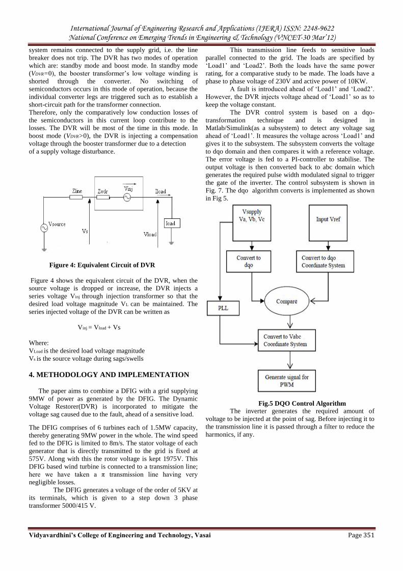
Figure 4: Equivalent Circuit of DVR
Figure 4 shows the equivalent circuit of the DVR, when the
source voltage is dropped or increase, the DVR injects a
series voltage Vinj through injection transformer so that the
desired load voltage magnitude VL can be maintained. The
series injected voltage of the DVR can be written as
Vinj = Vload + Vs
Where:
VLoad is the desired load voltage magnitude
Vs is the source voltage during sags/swells
4. METHODOLOGY AND IMPLEMENTATION
The paper aims to combine a DFIG with a grid supplying
9MW of power as generated by the DFIG. The Dynamic
Voltage Restorer(DVR) is incorporated to mitigate the
voltage sag caused due to the fault, ahead of a sensitive load.
The DFIG comprises of 6 turbines each of 1.5MW capacity,
thereby generating 9MW power in the whole. The wind speed
fed to the DFIG is limited to 8m/s. The stator voltage of each
generator that is directly transmitted to the grid is fixed at
575V. Along with this the rotor voltage is kept 1975V. This
DFIG based wind turbine is connected to a transmission line;
here we have taken a π transmission line having very
negligible losses.
The DFIG generates a voltage of the order of 5KV at
its terminals, which is given to a step down 3 phase
transformer 5000/415 V.
This transmission line feeds to sensitive loads
parallel connected to the grid. The loads are specified by
„Load1‟ and „Load2‟. Both the loads have the same power
rating, for a comparative study to be made. The loads have a
phase to phase voltage of 230V and active power of 10KW.
A fault is introduced ahead of „Load1‟ and „Load2‟.
However, the DVR injects voltage ahead of „Load1‟ so as to
keep the voltage constant.
The DVR control system is based on a dqo-
transformation technique and is designed in
Matlab/Simulink(as a subsystem) to detect any voltage sag
ahead of „Load1‟. It measures the voltage across „Load1‟ and
gives it to the subsystem. The subsystem converts the voltage
to dqo domain and then compares it with a reference voltage.
The error voltage is fed to a PI-controller to stabilise. The
output voltage is then converted back to abc domain which
generates the required pulse width modulated signal to trigger
the gate of the inverter. The control subsystem is shown in
Fig. 7. The dqo algorithm converts is implemented as shown
in Fig 5.
Fig.5 DQO Control Algorithm
The inverter generates the required amount of
voltage to be injected at the point of sag. Before injecting it to
the transmission line it is passed through a filter to reduce the
harmonics, if any.
International Journal of Engineering Research and Applications (IJERA) ISSN: 2248-9622 National Conference on Emerging Trends in Engineering & Technology (VNCET-30 Mar’12)
Vidyavardhini’s College of Engineering and Technology, Vasai Page 352
The MATLAB/SIMULINK model of our configured
model is shown below.
Fig 6. MATLAB/SIMULINK model of our proposed
system
Fig 7. MATLAB/SIMULINK model of the subsystem
4.1 SYSTEM PARAMETERS
The parameters used for the above Matlab/Simulink model
are tabulated as:
No. of wind turbines 6
Nominal stator voltage of DFIG 575 V
DC voltage to universal bridge 400 V
PWM generation mode 3 arm/6 pulse
Constant multiplier of dqo block 415
3 phase transformer voltage 5000/415
PI controller gains of d-block Kp-40, Ki-154
PI controller gains of q-block Kp-25, Ki-260
5. RESULTS AND ANALYSIS
A DFIG – grid system was simulated in Matlab/Simulink
with the DFIG being fed by a constant wind speed. A DVR
based voltage mitigation system was employed to maintain a
smooth voltage and power profile at the load end during fault.
The model was simulated for 1 second with different fault
scenarios from .5 seconds to .9 seconds.
We analysed the following parameters:
System voltage
Voltage across sensitive load(Load1) and test
load(load2)
The active power (in MW) and reactive power (in
MVAR)
We simulated the system for three phase fault and LLG (line-
line ground) faults.
Fig 8. A comparison of voltage profile generated by a)
DFIG and b) Three phase voltage source
Prior to all simulations a marked difference was observed
between the voltage profile of a three phase voltage source
like (synchronous generator or induction generator) and that
of a Doubly Fed Induction generator. As DFIG is a wind
driven device, it generates a voltage profile that is highly non-
International Journal of Engineering Research and Applications (IJERA) ISSN: 2248-9622 National Conference on Emerging Trends in Engineering & Technology (VNCET-30 Mar’12)
Vidyavardhini’s College of Engineering and Technology, Vasai Page 353
uniform by nature itself. Later in the simulations, in Fig.10, it
was observed that the DVR injects the voltage at the non
uniform sections of the DFIG voltage profile.
.
Fig 9. Voltage profile of a) DFIG b) across Load 1 c)
across Load 2 without mitigation by DVR during LLG
fault is seen.
The voltage profile generated by the DFIG is highly uneven
as seen from Fig.9. It is also seen that it takes an initial time
before it starts generating the required voltage. During LLG
fault, it can be noted that two phase of the voltages dip due to
the fault condition during 0.5 s to 0.9 s.
The case is same for 3 phase faults also. Here a dip will be
observed in all the 3 phases of the voltage profile.
Fig 10. Voltage profile of a) DFIG b) across Load 1
c) across Load 2 with mitigation by DVR during 3phase
fault is seen.
Similar to the LLG fault, a balanced 3 phase fault is given
during the period 0.5s to 0.9s and the sag is noticed during the
period. As 3 phase faults are severe in nature the scale of
voltage sag is also drastic.
Fig 11. Voltage profile of a) DFIG b) across Load 1 c)
across Load 2 with mitigation by DVR during LLG fault
is seen.
Voltage mitigation by DVR during LLG fault ahead of Load
1 is depicted in graph shown in fig. 11(b). The desired voltage
is obtained across Load 1 by fixing the parameters of the
control system. However, it is well inferred that the faulty
voltage profile is retained across Load 2, as in fig. 11(c).
The desired voltage across Load 1 is maintained around 150V
and it is generated by adjusting the DC voltage source to
400V.
Apart from the voltage sag analysis we analyse the active and
reactive power across the two loads Load 1 and Load 2.
Fig 12. Active and Reactive Power across Load 2, i.e.
power transmitted without mitigation
International Journal of Engineering Research and Applications (IJERA) ISSN: 2248-9622 National Conference on Emerging Trends in Engineering & Technology (VNCET-30 Mar’12)
Vidyavardhini’s College of Engineering and Technology, Vasai Page 354
Fig 13. Active and Reactive Power across Load 1, i.e.
power transmitted with mitigation
It is observed in Fig.12 that during fault condition the active
and reactive power drastically decreases and recovers once
the fault condition is cleared after 0.9s. However, it is clear
from Fig.13 that the active and reactive power is held at a
nominal value according to the load demand at Load 1 as the
DVR injects the voltage and mitigates the sag.
4. REFERENCES
[1] H.Chen,J Chen,D Shi ,X Duan, “Power flow study and
voltage stability analysis for distribution systems with
Distributed Generation” PESGM 2006,IEEE USA
,June 2006
[2] Jaswami, T.Thakur, “Minimum loss configuration of