Page 1
7/25/2019 Mitsu Turning Tools Insert Guide
http://slidepdf.com/reader/full/mitsu-turning-tools-insert-guide 1/110
A000
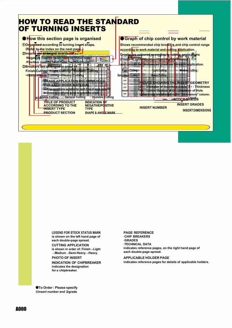
aHow this section page is organised aGraph of chip control by work material
zOrganised according to turning insert shape.
(Refer to the index on the next page.)
xInserts are arranged in order of :
·Negative inserts (with hole|without hole)·Positive inserts (with hole|without hole)
cBreakers are arranged in order of :
Finish Cutting|Light Cutting|Medium Cutting
|Semi-Heavy Cutting|Heavy Cutting
Shows recommended chip breakers and chip control range
according to work material and cutting application.
Graphs are coloured according to cutting applications
(Finish|Light|Medium|Semi-Heavy|Heavy)
and contain recommended breakers for each application.
INSERT NUMBER
PAGE REFERENCE·CHIP BREAKERS
·GRADES
·TECHNICAL DATA
indicates reference pages, on the right hand page of
each double-page spread.
INSERT GRADES
FIGURE SHOWING THE INSERT GEOMETRYD1 : Diameter of Inscribed Circle S1 : Thickness
Re : Corner Radius & D2 : Diameter of Hole
Dimensions are detailed in the "Dimensions" column.
APPLICABLE HOLDER PAGE
indicates reference pages for details of applicable holders.
aTo Order : Please specify
zinsert number and xgrade.
TITLE OF PRODUCTACCORDING TO THEINSERT TYPE
PRODUCT SECTION
GRADE APPLICATION RECOMMENDED
FOR EACH WORK MATERIALcutting conditions suitable for each type of work material
is shown as a general guide to select the grade.
LEGEND FOR STOCK STATUS MARKis shown on the left hand page of
each double-page spread.
CUTTING APPLICATIONis shown in order of: FinishLight
MediumSemi-HeavyHeavy.
PHOTO OF INSERT
INDICATION OF CHIPBREAKERindicates the designation
for a chipbreaker.
INDICATION OFNEGATIVE/POSITIVETYPE
SHAPE & ANGLE MARK
STOCK STATUS
INSERT DIMENSIONS
Finish Cutting :
HOW TO READ THE STANDARDOF TURNING INSERTS
Semi-Heavy Cutting :
Light Cutting : Medium Cutting :
Heavy Cutting :
: Stable Cutting : General Cutting : Unstable Cutting
Page 2
7/25/2019 Mitsu Turning Tools Insert Guide
http://slidepdf.com/reader/full/mitsu-turning-tools-insert-guide 2/110
A001
A002
A004
A006
A009
A010
A015
A016
A018
A019
A020
A022
A024
A025
A026
A027
A028
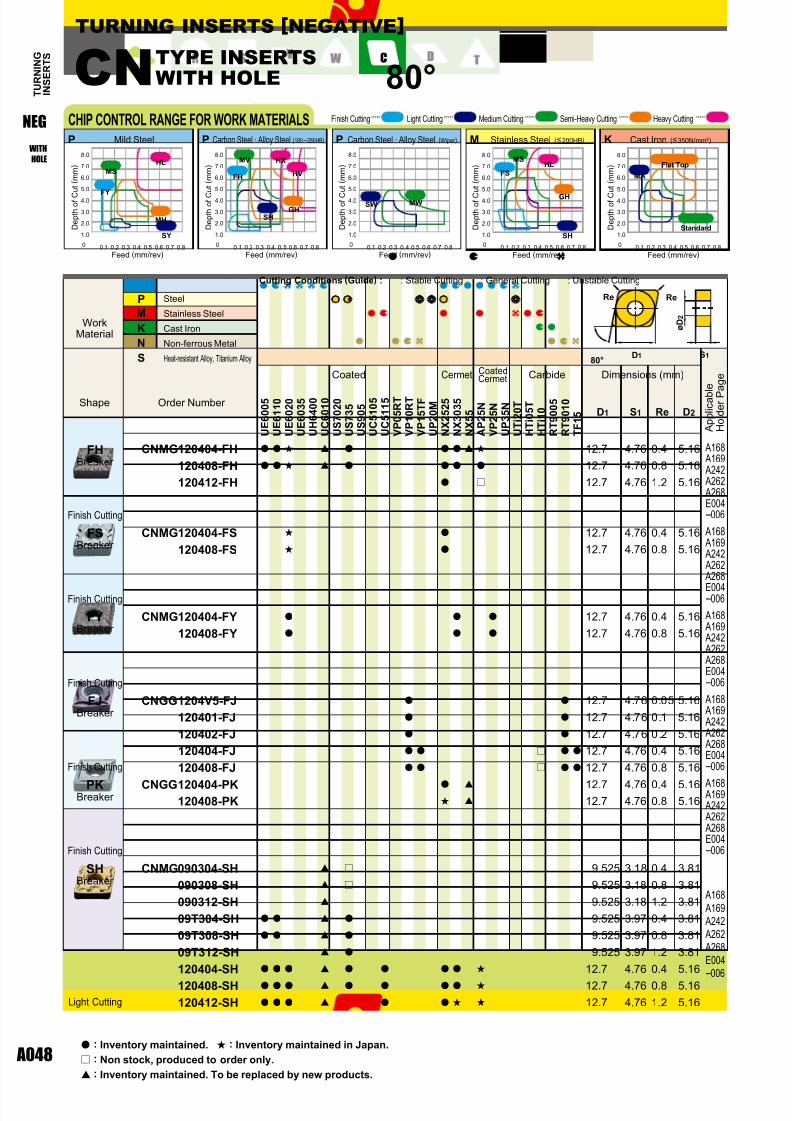
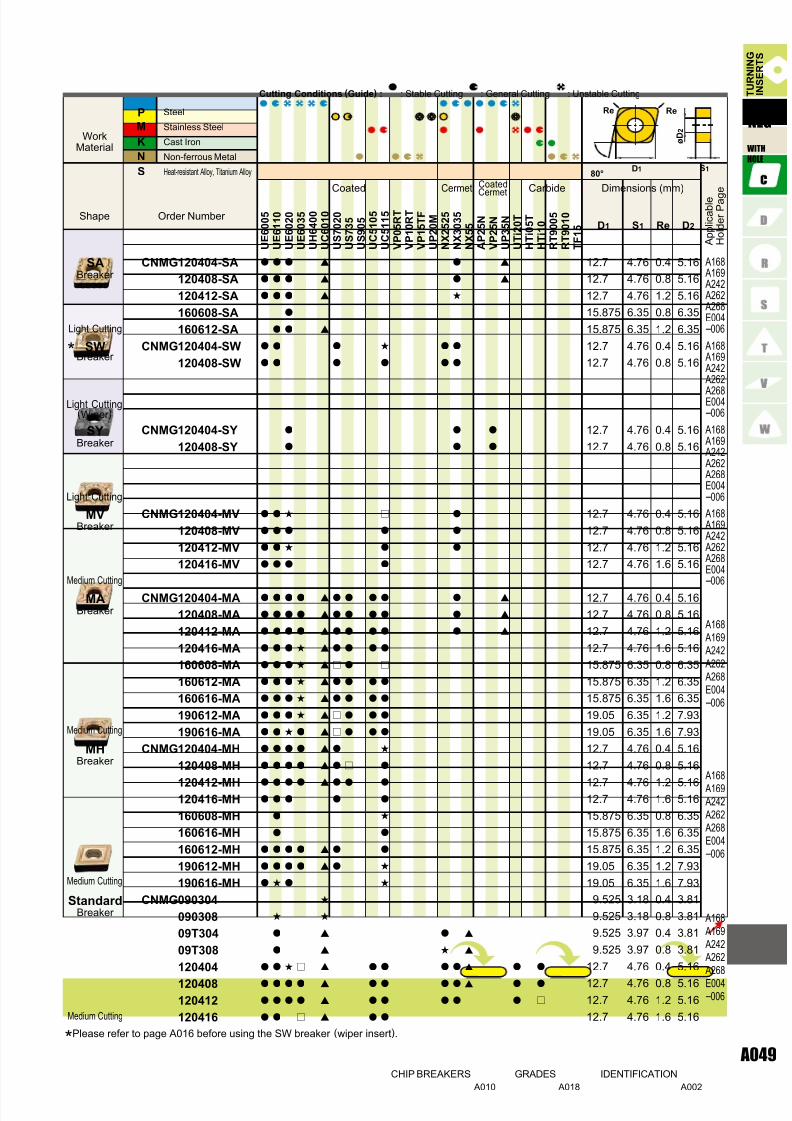
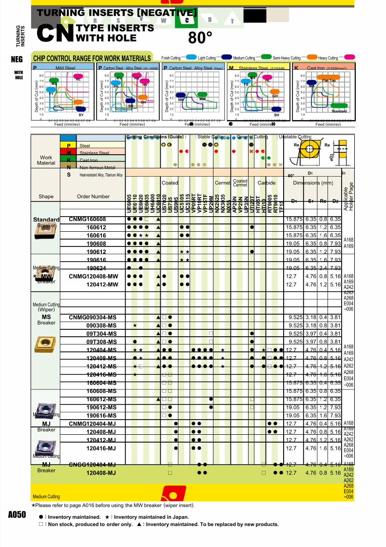
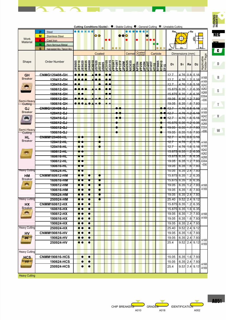
A048
A053
A057
A058
A062
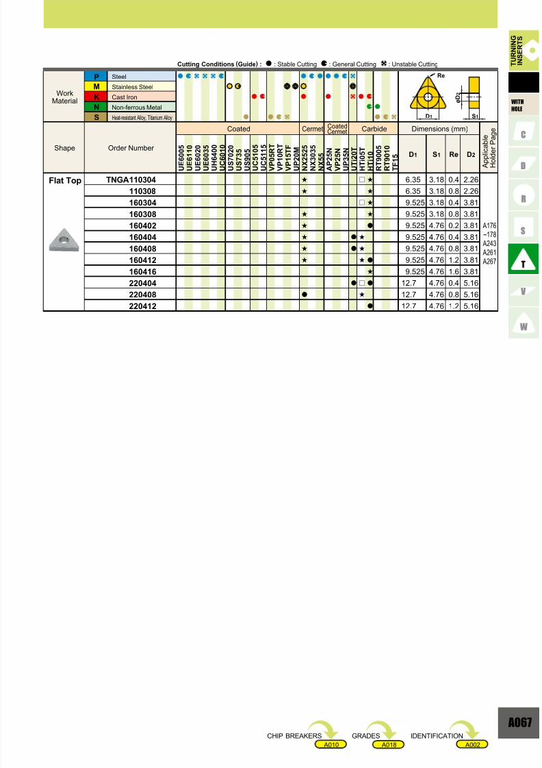
A068
A070
A073
A074
A075
A076
A078
A079
A084
A088
A089
A090
A091
A092
A093
A094
A095
A098
A099
A100
A101
A102
A103
A104
A106
A108
INSERT GRADESINSERT STANDARDS
INDENTIFICATION ...............................................................
HOLE GEOMETRY ...............................................................
PRECISION BREAKER SYSTEM ........................................
OUTLINE OF ...............................................
MITSUBISHI CARBIDE BREAKER SYSTEM......................
PRECISION BREAKER SYSTEM ........................................
WIPER INSERT.....................................................................
GRADES FOR TURNING .....................................................
TURNING APPLICATION RANGE .......................................
COATED CARBIDE (CVD) ...................................................
COATED CARBIDE (PVD) ...................................................
CERMET ...............................................................................
COATED CERMET ...............................................................
CEMENTED CARBIDE.........................................................
MICRO-GRAIN CEMENTED CARBIDE ...............................
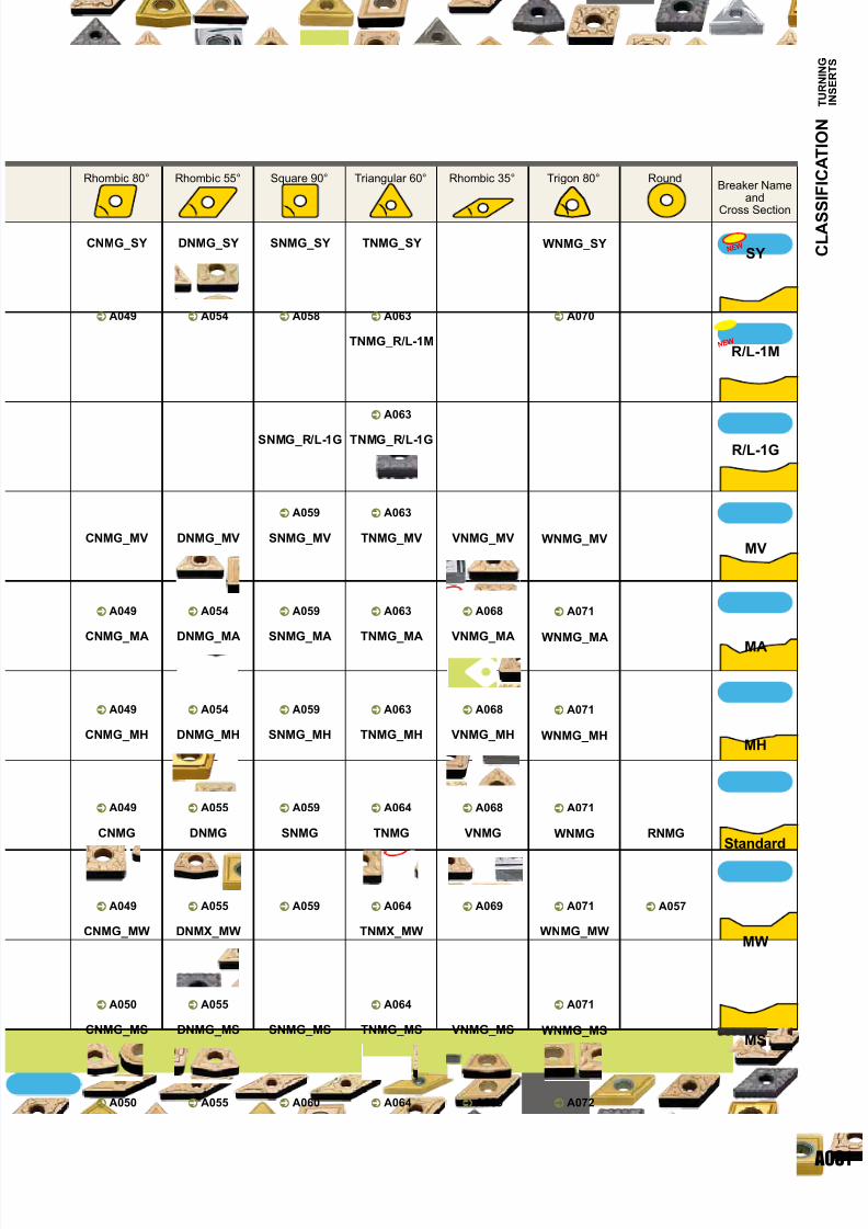
CLASSIFICATION OF INSERTS ..........................................
NEGATIVE INSERTS WITH HOLE CNooTYPE...RHOMBIC 80°............
DNooTYPE...RHOMBIC 55°............
RNooTYPE...ROUND ...................
SNooTYPE...SQUARE 90° .............
TNooTYPE...TRIANGULAR 60° .......
VNooTYPE...RHOMBIC 35° ............
WNooTYPE...TRIGON 80° ..............
NEGATIVE INSERTS WITHOUT HOLE
SNooTYPE...SQUARE 90° .............
TNooTYPE...TRIANGULAR 60° .......
KNooTYPE...PARALLELOGRAM 55° ...
POSITIVE INSERTS WITH HOLE
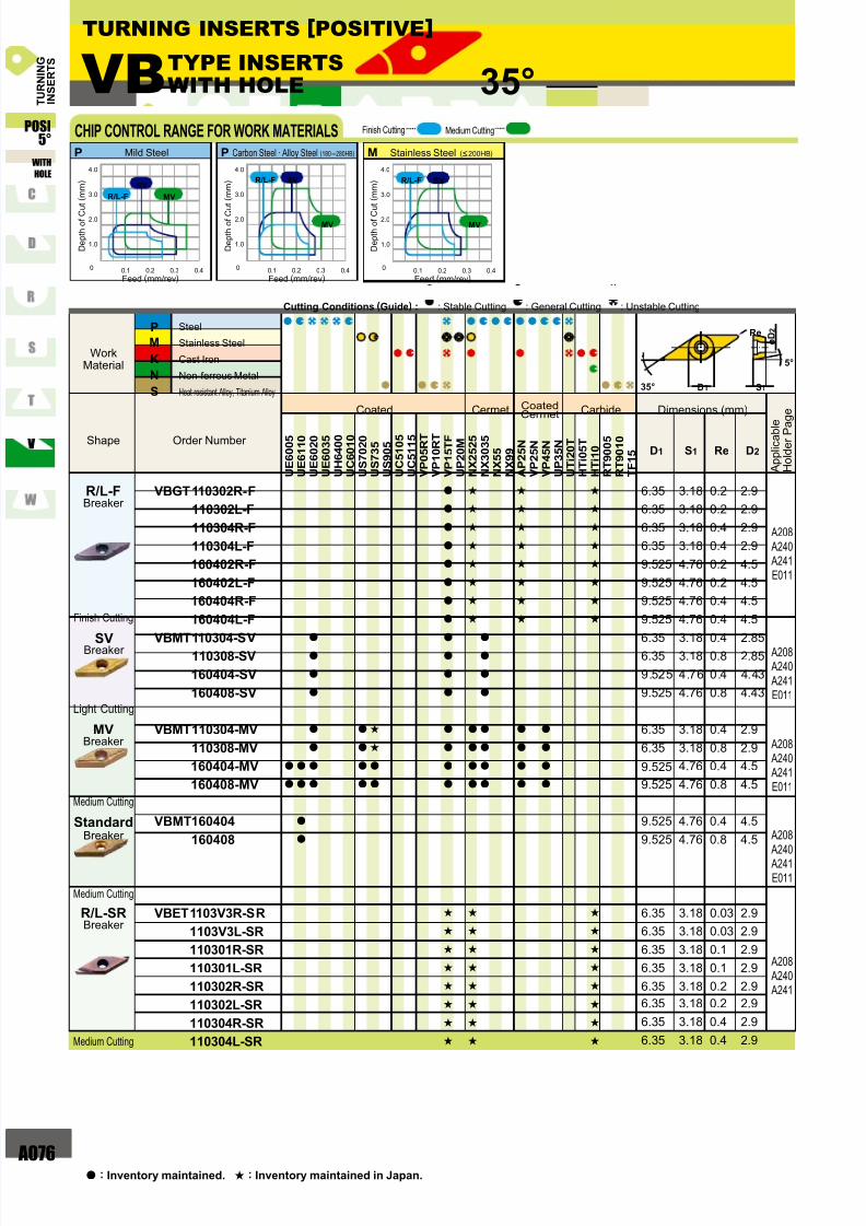
VBooTYPE...RHOMBIC 35° ............
WBooTYPE...TRIGON80°...............
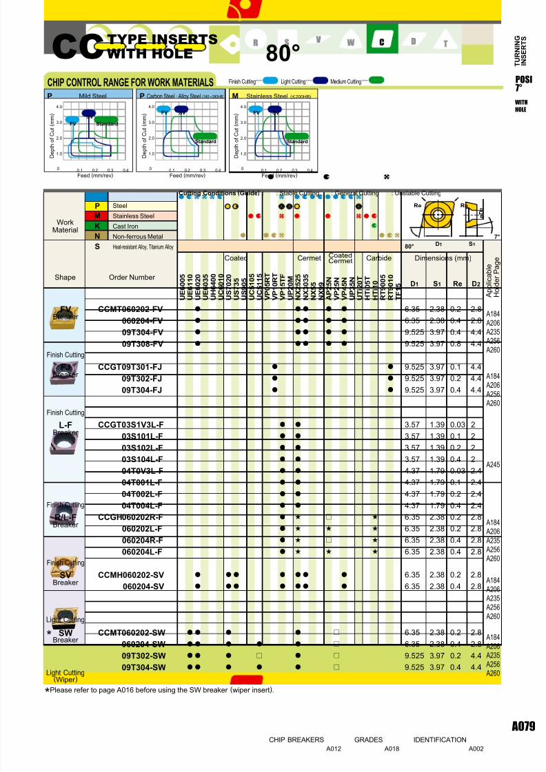
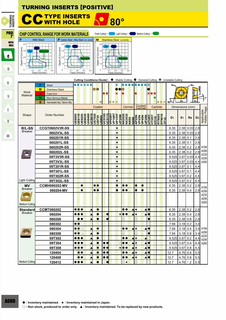
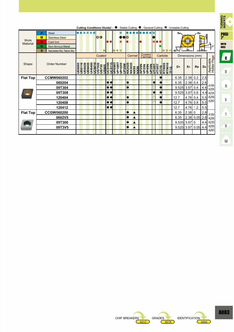
CCooTYPE...RHOMBIC 80°............
DCooTYPE...RHOMBIC 55°............
RCooTYPE...ROUND ...................
SCooTYPE...SQUARE 90° .............
TCooTYPE...TRIANGULAR 60° .......
VCooTYPE...RHOMBIC 35° ............
WCooTYPE...TRIGON 80° ..............
CPooTYPE...RHOMBIC 80°............
SPooTYPE...SQUARE 90° .............
TPooTYPE...TRIANGULAR 60°........
WPooTYPE...TRIGON 80° ..............
VDooTYPE...RHOMBIC 35° ............
DEooTYPE...RHOMBIC 55° ............
TEooTYPE...TRIANGULAR 60°........
RDooTYPE...ROUND ...................
RGooTYPE...ROUND ...................POSITIVE INSERTS WITHOUT HOLE
SPooTYPE...SQUARE 90° .............
TPooTYPE...TRIANGULAR 60°........
RTG TYPE..................................
TURNING
STANDARD OF INSERTS
Page 3
7/25/2019 Mitsu Turning Tools Insert Guide
http://slidepdf.com/reader/full/mitsu-turning-tools-insert-guide 3/110
002
H
O
P
S
T
C
D
E
F
M
V
W
L
A
B
K
R
e0.005
e0.005
e0.013
e0.013
e0.025
e0.025
e0.005
e0.013
e0.025
e0.08 e0.18
e0.08 e0.18
e0.13 e0.38
A
F
C
H
E
G
J
K
L
M
N
U
e0.025
e0.013
e0.025
e0.013
e0.025
e0.025
e0.05 e0.15
e0.05 e0.15
e0.05 e0.15
e0.05 e0.15
e0.05 e0.15
e0.08 e0.25
e0.025
e0.025
e0.025
e0.025
e0.025
e0.13
e0.025
e0.025
e0.025
e0.13
e0.025
e0.13
e0.08
e0.08
e0.13
e0.15
e0.15
e0.08
e0.08
e0.13
e0.15
e0.15
e0.11
e0.11
e0.15
e0.18
e0.18
e0.16
e0.16
e0.08
e0.08
e0.13
e0.15
e0.15
e0.18
e0.20
6.35
9.525
12.70
15.875
19.05
25.40
31.75
e0.05
e0.05
e0.08
e0.10
e0.10
e0.05
e0.05
e0.08
e0.10
e0.10
e0.05
e0.05
e0.08
e0.10
e0.10
e0.05
e0.05
e0.05
e0.05
e0.08
e0.10
e0.10
e0.13
e0.15
6.35
9.525
12.70
15.875
19.05
25.40
31.75
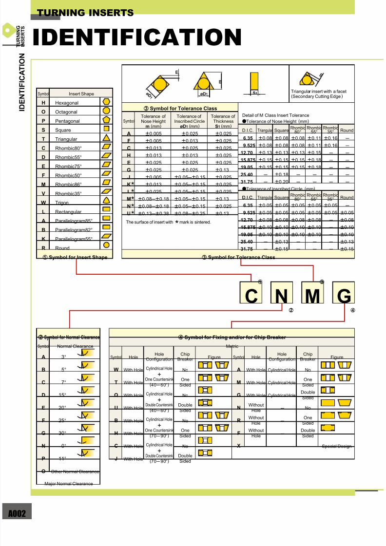
C N M G
A 3°
B 5°
C 7°
D 15°
E 20°
F 25°
G 30°
N 0°
P 11°
O
W
T
Q
U
B
H
C
J
A
M
G
N
R
F
X
z c
x v
e0.05
e0.08
e0.10
e0.10
e0.13
e0.15
(40 60°)
(40 60°)
(70 90°)
(70 90°)
m
ø D 1 øD1
m
m
S1
IDENTIFICATION
TURNING INSERTS
Triangular insert with a facet
(Secondary Cutting Edge)Symbol
Hexagonal
Octagonal
Pentagonal
Square
Triangular
Rhombic80°
Rhombic55°
Rhombic75°
Rhombic50°
Rhombic86°
Rhombic35°
Trigon
Rectangular
Parallelogram85°
Parallelogram82°
Parallelogram55°
Round
Insert Shape
Symbol
The surface of insert with * mark is sintered.
Tolerance ofNose Height
m (mm)
Tolerance of Inscribed Circle
øD1 (mm)
Tolerance ofThicknessS1 (mm)
D.I.C. Triangular SquareRhombic
80°Rhombic
55°Rhombic
35°
SquareRhombic
80°Rhombic
55°Rhombic
35°
Round
D.I.C. Triangular RoundD.I.C.
Detail of M Class Insert Tolerance
aTolerance of Nose Height (mm)
aTolerance of Inscribed Circle (mm)
Symbol
Symbol HoleHole
ConfigurationChip
Breaker Chip
Breaker Figure Symbol HoleHole
Configuration Figure
With Hole
With Hole
With Hole
With Hole
With Hole
With Hole
With Hole
With Hole
With Hole
With Hole
With Hole
Without
Hole
Without
Hole
Without
Hole
Special Design
Cylindrical Hole
Cylindrical Hole
Cylindrical Hole
Cylindrical Hole
+One Countersink
Cylindrical Hole
+Double Countersink
Cylindrical Hole
+One Countersink
Cylindrical Hole
+Double Countersink
Double
Sided
Double
Sided
No
No
No
No
OneSided
Double
Sided
Double
Sided
No
No
OneSided
One
Sided
One
Sided
Other Normal Clearance
Major Normal Clearance
Normal Clearance Metric
z Symbol for Insert Shape
c Symbol for Tolerance Class
x Symbol for Normal Clearance v Symbol for Fixing and/or for Chip Breaker
c Symbol for Tolerance Class
*****
I D E N T I F I C A T I O N
T U R N I N G
I N S E R T S
Page 4
7/25/2019 Mitsu Turning Tools Insert Guide
http://slidepdf.com/reader/full/mitsu-turning-tools-insert-guide 4/110
A003
L302
03
08
09
0405
06
0304
05
0304
05
06
S1
01
T0
02
T2
03
T3
04
0607
09
1.39
1.59
1.79
2.38
2.78
3.18
3.97
4.76
6.357.94
9.52
00
V3
V5
01
02
04
08
12
16
20
24
28
32
0.03
0.05
0.1
0.2
0.4
0.8
1.2
1.6
2.0
2.4
2.8
3.2
08
09
06
04 11
13
07 06 06 11
09 08 07 1305
08
09 06 16 11 09 09 16
10
12
12 08 22 15 12 12 22
19 16 15 27
23 19 19 33
27 22 22 38
31 25 25 44
38 32 31 54
10
16
19
20
25
25
31
32
13
3.974.76
5.56
6.00
6.35
7.94
8.00
9.525
10.00
12.00
12.70
15.875
16.00
19.05
20.00
22.225
25.00
25.40
31.75
32.00
12 04 08 (E) (N) MV-
F
E
T
S
R
L
N
FJFH
FS FV
GJGH
FY
HX
HL
HM HV
MA MJ
MS MV MW
SH
MH
SA SW
b n /
m , .
Sharp NoseSharp
Cutting Edges
Round
Cutting Edges
Chamfered
Cutting Edges
Chamfered
and Rounded
Cutting Edges
Symbol
Symbol Figure Cutting Edge Symbol Figure
Standard
Hand SymbolCorner Radius (mm)
Symbol Thickness (mm)
Diameter of
Inscribed Circle(mm)
b Symbol for Insert Size
m Symbol for Insert Corner Configuration , Symbol for Cutting Edge Condition . Symbol for Cutting Direction
n Symbol for Insert Thickness
/ Symbol for Chip Breaker
Round Insert
Mitsubishi Materials omit
the honing symbol.
(Refer to JIS-B4120-1998)
Right
Left
Neutral
*Thickness is from the bottom of the insert to the top of the cutting edge.
I D E N
T I F I C A T I O N
InchMetric00 :M0 :
T U R N I N G
I N S E R T S
Page 5
7/25/2019 Mitsu Turning Tools Insert Guide
http://slidepdf.com/reader/full/mitsu-turning-tools-insert-guide 5/110
004
C N G A
CNGG
CNMA
CNMG
CNMM
D N G A
DNGG
DNGM
DNMA
DNMG
DNMM
DNMX
S N G A
SNGG
S N M A
SNMG
SNMM
T N G A
TNGG
T N M A
TNMG
TNMM
T N M X
V N G A
VNGM
VNGG
VNMG
VNMM
WNMA
WNMG
RNMG
3.81
3.81
5.16
6.35
7.93
9.12
3.81
5.16
5.16
3.81
5.16
6.35
7.93
9.12
9.12
2.26
3.81
3.81
5.16
6.35
7.93
3.81
3.813.81
3.81
5.16
3.81
5.16
6.35
7.93
9.12
12.7
A
A
A
A
A
A
A
A
A
A
A
A
A
A
A
A
A
A
A
A
A
A
A A
A
A
A
A
A
A
A
A
0903pp
0904pp
1204pp
1606pp
1906pp
2509pp
1104pp
1504pp
1506pp
0903pp
1204pp
1506pp
1906pp
2507pp
2509pp
1103pp
1603pp
1604pp
2204pp
2706pp
3309pp
1604pp
0603pp
06T3pp
0604pp
0804pp
090300
120400
150600
190600
250900
310900
D2
C C E T
C C G T
CCMT
CCGB
CCMB
CCGH
CCMH
CCGW
CCMW
C P G T
CPMX
D E G X
C P G B
CPMBCPMH
D C E T
D C G T
DCGW
DCMW
DCMT
RCMX
RCMT
RGGM
2.8
4.4
2.8
2.0
2.4
2.8
4.4
2.8
3.4
4.4
5.5
2.8
4.4
5.5
3.4
4.4
3.5
4.5
3.5
4.6
2.8
4.4
2.8
4.4
5.5
5.1
3.64.2
5.2
6.5
7.2
9.5
2.8
3.4
5.6
B
B
B
B
B
B
BB
B
B
B
B
B
B
B
B
D
D
D
D
B
B
B
B
B
C
DD
D
D
D
D
B
B
C
0602pp
09T3pp
0602pp
03S1pp
04T0pp
0602pp
09T3pp
0602pp
0803pp
09T3pp
1204pp
0602pp
09T3pp
1204pp
0802pp
0903pp
0802pp
0903pp
0802pp
0903pp
0702pp
11T3pp
0702pp
11T3pp
1504pp
1504pp
1003M01204M0
1606M0
2006M0
2507M0
3209M0
0602M0
0803M0
2004M0
D2
3.8
6.0
3.9
2.9
3.5
3.8
6.0
3.8
4.5
6.0
7.5
3.8
6.0
7.5
4.5
6.0
5.3
6.3
5.6
6.6
3.8
6.0
3.8
6.0
7.5
7.0
4.65.4
6.7
8.0
9.1
11.7
3.8
4.5
7.5
D3
ø D 3
ø D 2
ø D 3
ø D 2
ø D 3
ø D 2
ø D 2
NEGATIVE
HOLE GEOMETRY
TURNING INSERTS
Insert NumberDimension (mm)
Hole Type
POSITIVE
Insert NumberDimensions (mm)
Hole Type
Type DType CType BType A
H O L E G
E O M E T R Y
T U R N I N G
I N S E R T S
Page 6
7/25/2019 Mitsu Turning Tools Insert Guide
http://slidepdf.com/reader/full/mitsu-turning-tools-insert-guide 6/110
A005
WBGT
WBMT
WPGT
WPMT
WCGT
WCMT
WCMW
2.3
2.3
2.3
2.3
2.8
4.4
2.8
4.4
B
B
B
B
B
B
B
B
0201pp
L302pp
0201pp
L302pp
0402pp
06T3pp
0402pp
0603pp
D2
3.2
3.2
3.0
3.0
3.8
6.0
3.8
6.0
D3
S C M T
SCMW
T C G TT C M T
TCGW
TCMW
SPMW
S P M T
S P G X
T E G X
T P G X
T P M X
T P G V
T P G T
V C G T
V C M T
VCGW
VCMW
T P G B
T P M B
T P G H
T P M H
V B E TV B G T
V B M T
VBGW
V D G X
4.4
5.5
4.6
5.7
4.4
5.5
4.8
5.9
2.3
2.3
2.5
2.8
3.4
4.4
4.4
2.5
3.0
3.5
4.8
2.7
3.2
3.7
4.8
2.4
2.9
3.4
4.4
2.8
3.4
4.4
2.94.4
2.4
2.8
4.4
4.5
B
B
B
B
B
B
D
D
B
BB
B
B
B
D
C
C
C
D
C
C
C
D
D
D
D
D
B
B
B
BB
B
B
B
D
09T3pp
1204pp
0903pp
1203pp
0903pp
1203pp
0903pp
1203pp
0601pp
0802pp
0902pp
1102pp
1303pp
16T3pp
1603pp
0802pp
0902pp
1103pp
1603pp
0802pp
0902pp
1103pp
1603pp
0802pp
0902pp
1103pp
1603pp
0902pp
1103pp
1603pp
1103pp
1604pp
0802pp
1103pp
1604pp
1603pp
D2
6.0
7.5
6.0
7.5
6.0
7.5
6.4
7.7
3.2
3.0
3.3
3.8
4.5
6.0
6.1
3.8
4.3
4.8
6.4
3.8
4.3
4.8
6.4
4.0
4.3
4.8
6.5
3.8
4.5
6.0
3.86.0
3.2
3.8
6.0
6.1
D3
ø D 3
ø D 2
ø D 3
ø D 2
ø D 3
ø D 2
ø D 2
POSITIVE
Insert NumberDimensions (mm)
Hole TypeInsert NumberDimensions (mm)
Hole Type
H O L E G E O M E T R Y
T U R N I N G
I N S E R T S
Type DType CType BType A
Page 7
7/25/2019 Mitsu Turning Tools Insert Guide
http://slidepdf.com/reader/full/mitsu-turning-tools-insert-guide 7/110
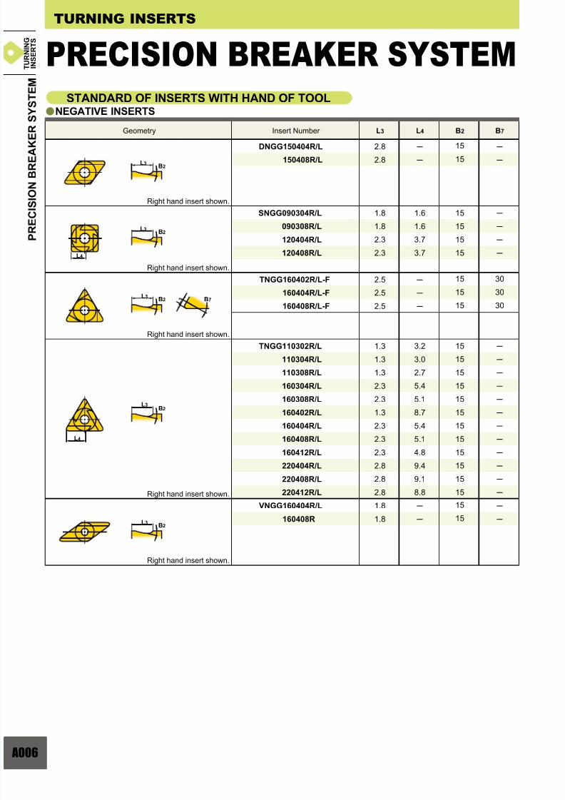
006
L3 L4 B2 B7
DNGG150404R/L
150408R/L
2.8
2.8
15
15
1.8
1.8
2.3
2.3
1.6
1.6
3.7
3.7
15
15
15
15
SNGG090304R/L
090308R/L
120404R/L
120408R/L
TNGG160402R/L-F
160404R/L-F
160408R/L-F
2.5
2.5
2.5
15
15
15
30
30
30
TNGG110302R/L
110304R/L
110308R/L
160304R/L
160308R/L
160402R/L
160404R/L
160408R/L
160412R/L
220404R/L
220408R/L
220412R/L
1.3
1.3
1.3
2.3
2.3
1.3
2.3
2.3
2.3
2.8
2.8
2.8
3.2
3.0
2.7
5.4
5.1
8.7
5.4
5.1
4.8
9.4
9.1
8.8
15
15
15
15
15
15
15
15
15
15
15
15
VNGG160404R/L
160408R
1.8
1.8
15
15
a
L3B2
L3
L4
B2
L3
L 3B2 B7
L4
L3B2
L3B2
TURNING INSERTS
STANDARD OF INSERTS WITH HAND OF TOOLNEGATIVE INSERTS
Geometry Insert Number
Right hand insert shown.
Right hand insert shown.
Right hand insert shown.
Right hand insert shown.
Right hand insert shown.
P R E C I S I O N B R E A K E
R S Y S T E M
PRECISION BREAKER SYSTEM T U R N I N G
I N S E R T S
Page 8
7/25/2019 Mitsu Turning Tools Insert Guide
http://slidepdf.com/reader/full/mitsu-turning-tools-insert-guide 8/110
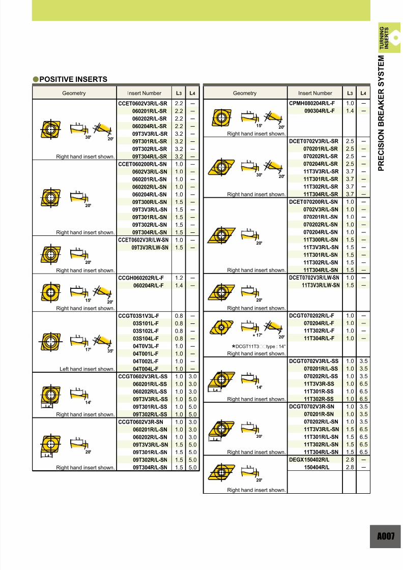
A007
CCET 0602V3R/L-SR
060201R/L-SR
060202R/L-SR
060204R/L-SR
09T3V3R/L-SR
09T301R/L-SR
09T302R/L-SR
09T304R/L-SR
CCET 060200R/L-SN
0602V3R/L-SN
060201R/L-SN
060202R/L-SN
060204R/L-SN
09T300R/L-SN
09T3V3R/L-SN
09T301R/L-SN
09T302R/L-SN
09T304R/L-SN
CCET 0602V3R/LW-SN
09T3V3R/LW-SN
CCGH 060202R/L-F
060204R/L-F
CCGT 03S1V3L-F
03S101L-F
03S102L-F
03S104L-F
04T0V3L-F
04T001L-F
04T002L-F
04T004L-F
CCGT 0602V3R/L-SS
060201R/L-SS
060202R/L-SS
09T3V3R/L-SS
09T301R/L-SS
09T302R/L-SS
CCGT 0602V3R-SN
060201R/L-SN
060202R/L-SN
09T3V3R/L-SN
09T301R/L-SN
09T302R/L-SN
09T304R/L-SN
2.2
2.2
2.2
2.2
3.2
3.2
3.2
3.2
1.0
1.0
1.0
1.0
1.0
1.5
1.5
1.5
1.5
1.5
1.0
1.5
1.2
1.4
0.8
0.8
0.8
0.8
1.0
1.0
1.0
1.0
1.0
1.0
1.0
1.0
1.0
1.0
1.0
1.0
1.0
1.5
1.5
1.5
1.5
3.0
3.0
3.0
5.0
5.0
5.0
3.0
3.0
3.0
5.0
5.0
5.0
5.0
CPMH 080204R/L-F
090304R/L-F
DCET 0702V3R/L-SR
070201R/L-SR
070202R/L-SR
070204R/L-SR
11T3V3R/L-SR
11T301R/L-SR
11T302R/L-SR
11T304R/L-SR
DCET 070200R/L-SN
0702V3R/L-SN
070201R/L-SN
070202R/L-SN
070204R/L-SN
11T300R/L-SN
11T3V3R/L-SN
11T301R/L-SN
11T302R/L-SN
11T304R/L-SN
DCET 0702V3R/LW-SN
11T3V3R/LW-SN
DCGT 070202R/L-F
070204R/L-F
11T302R/L-F
11T304R/L-F
DCGT 0702V3R/L-SS
070201R/L-SS
070202R/L-SS
11T3V3R-SS
11T301R-SS
11T302R-SS
DCGT 0702V3R-SN
070201R-SN
070202R/L-SN
11T3V3R/L-SN
11T301R/L-SN
11T302R/L-SN
11T304R/L-SN
DEGX 150402R/L
150404R/L
1.0
1.4
2.5
2.5
2.5
2.5
3.7
3.7
3.7
3.7
1.0
1.0
1.0
1.0
1.0
1.5
1.5
1.5
1.5
1.5
1.0
1.5
1.0
1.0
1.0
1.0
1.0
1.0
1.0
1.0
1.0
1.0
1.0
1.0
1.0
1.5
1.5
1.5
1.5
2.8
2.8
3.5
3.5
3.5
6.5
6.5
6.5
3.5
3.5
3.5
6.5
6.5
6.5
6.5
L3 L4 L3 L4
a
L3
30°
15°
20°
20°
15°
L 3
20°
L 3
35°
L 3
20°
L4
L4
L 3
20°
L 3
20°
L 3
20°
L4
L4
17°
14°
20°
30°
20°
20°
17°
14°
20°
20°
L3
L3
L3
L3
L3
L3
L3
L3
L3
L3
L3
L3
L3
L3
Geometry Insert Number Geometry Insert Number
POSITIVE INSERTS
Right hand insert shown.
Right hand insert shown.
Right hand insert shown.
Right hand insert shown.
Right hand insert shown.
Right hand insert shown.
Right hand insert shown.
Right hand insert shown.
Right hand insert shown.
Right hand insert shown.
Right hand insert shown.
Left hand insert shown.
Right hand insert shown.
Right hand insert shown.
*DCGT11T3pptype : 14°
Right hand insert shown.
*
P R E C I S I O N B R E A K E
R S Y S T E M
T U R N I N G
I N S E R T S
Page 9
7/25/2019 Mitsu Turning Tools Insert Guide
http://slidepdf.com/reader/full/mitsu-turning-tools-insert-guide 9/110
008
L3 L4 L3 L4
DEGX 150402R/L-F
150404R/L-F
TCGT 0601V3L-F
060101L-F
060102R/L-F
060104R/L-F
TEGX 160302R/L
160304R/L
TPGH 080202R/L-FS
080204R/L-FS
090202R/L-FS
090204R/L-FS
110302R/L-FS
110304R/L-FS
160304R/L-FS
160308R/L-FS
TPGR 110304R/L
160304R/L
160308R/L
TPGX 080202R/L
080204R/L
090202R/L
090204R/L
090208R/L
110302R/L
110304R/L
110308R/L
VBGT 110302R/L-F
110304R/L-F
160402R/L-F
160404R/L-F
VBET 1103V3R/L-SR
110301R/L-SR
110302R/L-SR
110304R/L-SR
VBET 110300R/L-SN
1103V3R/L-SN
110301R/L-SN
110302R/L-SN
110304R/L-SN
VBET1103V3R/LW-SN
VCGT 080202R/L-F
080204R/L-F
VDGX 160302R/L
160304R/L
WBGT 0201V3L-F
020101L-F
020102L-F
020104L-F
L302V3L-F
L30201L-F
L30202R/L-F
L30204R/L-F
WCGT 020102R/L
020104R/L
L30202R/L
L30204R/L
WPGT 040202R/L-FS
040204R/L-FS
060304R/L-FS
060308R/L-FS
2.5
2.5
1.0
1.0
1.0
1.0
2.0
2.0
0.9
0.9
1.0
1.0
1.4
1.4
2.0
2.0
1.3
2.3
2.3
1.3
1.3
1.6
1.6
1.6
1.8
1.8
1.8
6.0
6.0
3.0
5.4
5.1
1.0
1.5
1.5
1.5
2.5
2.5
2.5
2.5
1.0
1.0
1.0
1.0
1.0
1.0
0.8
0.8
2.0
2.0
1.0
1.0
1.0
1.0
1.0
1.0
1.0
1.0
1.0
1.0
1.0
1.0
1.0
1.0
1.0
1.0
a
L 3
20°
L 3
20°
L4
L4
L 3
20°
L 3
20°
L 3
20°
L 3
20°
L 3
30°
L 3
20°
L 3
30°
L 3
20°25°
14°
20°
15°
15°
L 3
20°10°
13°
30°
20°
20°
13°
25°
13°
15°
15°
L3
L3
L3
L3
L3
L3
L3
L3
L3
L3
L3
L3
L3
L3
L3
TURNING INSERTS
STANDARD OF INSERTS WITH HAND OF TOOLPOSITIVE INSERTS
Right hand insert shown.
Left hand insert shown.
Right hand insert shown.
Right hand insert shown.
Right hand insert shown.
Right hand insert shown.
Right hand insert shown.
Left hand insert shown.
Right hand insert shown.
Right hand insert shown.
Right hand insert shown.
Right hand insert shown.
Right hand insert shown.
Right hand insert shown.
Geometry Insert Number Geometry Insert Number
*TPGH1603pptype : 14°
Right hand insert shown.
*
PRECISION BREAKER SYSTEM
P R E C I S I O N B R E A K E
R S Y S T E M
T U R N I N G
I N S E R T S
Page 10
7/25/2019 Mitsu Turning Tools Insert Guide
http://slidepdf.com/reader/full/mitsu-turning-tools-insert-guide 10/110
A009
UE6005
UE6110
UE6020
UE6035
AP25N
VP25N
UP35N
1.19
1.23
1.19
140HB 180HB 220HB 260HB
1.0
1.0
1.0
0.85
0.85
0.91
0.75
0.72
0.85
P
M
K
1.00
1.00
1.00
1.00
1.00
1.00
1.00
0.81
0.82
0.83
0.88
0.84
0.84
0.87
0.71
0.72
0.74
0.82
0.76
0.76
0.80
0.65
0.67
0.69
0.78
0.71
0.71
0.75
0.57
0.59
0.62
0.73
0.64
0.64
0.69
UC5105
UC5115
AP25N
VP25N
1.00
1.00
1.00
1.00
0.79
0.79
0.87
0.87
0.69
0.69
0.80
0.80
0.63
0.63
0.75
0.75
0.55
0.55
0.69
0.69
US735
US7020
VP15TF
AP25N
1.00
1.00
1.00
1.00
0.78
0.70
0.78
0.76
0.68
0.57
0.67
0.65
0.61
0.49
0.61
0.57
0.53
0.40
0.52
0.49
PP
MM
KK
M
M
M
y
a
a a
y
y
y
zxcv
Cutting speed affects tool life. Mitsubishi's suggests cutting speeds for 15 90 minute tool life and is based on Taylor's
equation (Relationship for tool grade, cutting conditions and tool life). When the customer requires a different tool life, obtain coefficient
values of the grade you use from the charts below. Multiply the coefficient values by the cutting speed to calculate a new cutting speed.
Hardness of the work material also affects tool life. Mitsubishi's suggests cutting speed variations when material
hardness differs. Obtain the suitable coefficient value for each type of work material from the chart below. Multiply the coefficient
value by the recommended cutting speed of the grade used to calculate a new cutting speed.
supports our customers with information and suitable cutting conditions for each work material by selecting the
optimum indexable insert together with a suitable tool life expectancy.
OUTLINE
HARDNESS OF THE WORK MATERIAL
TOOL LIFE
LABEL INDICATION
zCutting conditionsStable cutting General cutting Unstable cutting
xCutting areasF : Finishing (ap<0.5mm) S : Light Cutting (ap=0.51.5mm)
M : Medium Cutting (ap=1.5 4.0mm) G : Rough Cutting (ap=4.0 7.0mm)
cCutting speed standards(Performance versus tool life)
Calculations based on maximum performance : Tool life is 15min.
Calculation based on maximum tool life : Tool life is 90min.
vWork materialsP : Steel (Material reference : Carbon steel, alloy steel 180HB)
M : Stainless steel (Material reference : Austenitic stainless steel 180HB)
K : Cast iron (Material reference : Grey cast iron, ductile cast iron 180HB)
P Grade (Steel) cutting speed coefficient values. K Grade (Cast lron) cutting speed coefficient values.
M Grade (Stainless Steel) cutting speed coefficient values.
(ex.) Medium cutting of steel
: UE6110 : CNMG120408-MA : vc=315m/min
The 1st recommendationIndexable insertsRecommended cutting speed(Tool life : 15min.)
Tool life required by the customer : 30min.
315×0.82i260m/min
Work materialSoft Hard(Hardness of workpiece)
O U T L I N E O F
Tool lifeGrade
Tool lifeGrade
Tool lifeGrade
Steel
Stainless
Cast Iron C u t t i n g C o n d i t i o n s
vc (Cutting Speed)
320190 m/min1050620 SFM
220120 m/min720390 SFM
270170 m/min885560 SFM
15min 30min 45min 60min 90min
15min 30min 45min 60min 90min 15min 30min 45min 60min 90min
T U R N I N G
I N S E R T S
Page 11
7/25/2019 Mitsu Turning Tools Insert Guide
http://slidepdf.com/reader/full/mitsu-turning-tools-insert-guide 11/110
010
FY
VP25N
FY
UE6020
MS
NX3035
SY
VP25N
SY
UE6020
HL
UE6110
MH
UE6005
HL
UE6020
MH
UE6020
MS
UE6020
HZZ
HL
MHH
MH UE6020E6020UE6020
UE6110E6110UE6110 MSS
MS
UC6110C6110UE6110
NX3035X3035NX3035
SYY
SY
FYY
FY
NX3035X3035NX3035
FH
AP25N
FH
UE6110
MV
UE6005
SH
UE6005
SH
UE6020
HX
UE6110
GH
UE6005
HX
UH6400
GH
UE6020
MV
UE6020
HXX
HX
GHH
GHUE6020E6020UE6020
UE6110E6110UE6110MVV
MV
UC6110C6110UE6110
UE6110E6110UE6110
SHH
SH
FHH
FH
NX3035X3035NX3035
GH
US7020
MS
US7020
SH
US735
FS
NX2525
GH
US735
MS
US735
SH
US735
FS
NX2525
GH
MS
SH
FS
US735
US735
US735
NX2525
HL
UE6020
HL
UE6020
HL
UE6020
a
y y
TURNING INSERTS
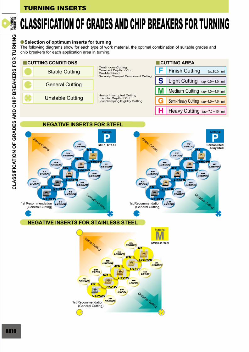
Selection of optimum inserts for turningThe following diagrams show for each type of work material, the optimal combination of suitable grades and
chip breakers for each application area in turning.
CUTTING CONDITIONS
Stable Cutting
General Cutting
Unstable Cutting
Continuous CuttingConstant Depth of CutPre-MachinedSecurely Clamped Component Cutting
Heavy Interrupted CuttingIrregular Depth of CutLow Clamping Rigidity Cutting
Finish Cutting
Light Cutting
Medium Cutting
Heavy Cutting
Semi-Heavy Cutting
CUTTING AREA
NEGATIVE INSERTS FOR STEEL
NEGATIVE INSERTS FOR STAINLESS STEEL
(ap<0.5mm)
(ap=0.5 1.5mm)
(ap=1.5 4.0mm)
(ap=7.0 10mm)
(ap=4.0 7.0mm)
Material
S t a b l e C u t t i n g
S t a b l e C u t t i n g
S t a b l e
C u t t i n g
1st Recommendation(General Cutting)
1st Recommendation(General Cutting)
1st Recommendation
(General Cutting)
Material
Stainless Steel
Mild Steel Carbon SteelAlloy Steel
Material
U n s t a b l e C u t t i n g
U n s t a b l e C u t t i n g
U n s t a b l e C u t t i n g
C L A S S I F I C A T I O N O F G R A D E S
A N D C H I P B R E A K E R S F O R T U R N I N G
CLASSIFICATION OF GRADES AND CHIP BREAKERS FOR TURNING T U R N I N G
I N S E R T S
Page 12
7/25/2019 Mitsu Turning Tools Insert Guide
http://slidepdf.com/reader/full/mitsu-turning-tools-insert-guide 12/110
A011
A028
FJ
VP10RT
FJ
VP15TF
FJ
RT9010
FJ
TF15
FJ
VP10RT
GJ
VP10RT
MS
VP05RT
MJ
VP05RT GJ
VP15TF
MS
VP15TF
MJ VP15TF
MJ
VP10RT
MS
VP10RT
GJ
VP10RT
FJ
RT9010
GJ
RT9010
MS
RT9005
MJ
RT9010 GJ
TF15
MS
TF15
MJ TF15
MJ
RT9010
MS
RT9010
GJ
RT9010
R/L-F
NX2525
MA
UC5105
R/L-F
NX2525
MA
UC5115
R/L-F
NX2525
MA
UC5115
UC5115
UC5115
UC5105
UC5105
UC5115
UC5115
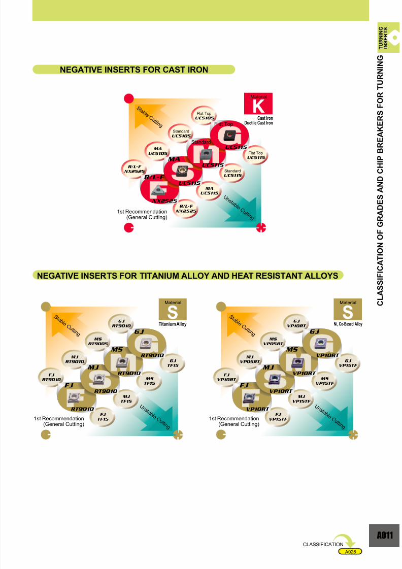
NEGATIVE INSERTS FOR CAST IRON
Material
Material
Flat Top
Standard
Flat Top
Standard
Standard
Flat TopCast Iron
Ductile Cast Iron
Ni, Co-Based Alloy
Material
Titanium Alloy
C L A S S I F I C A T I O N O F G R A D E S
A N D C H I P B R E A K E R S F O R T U R N I N G
S t a b l e C u t t i n g
S t a b l e C u t t i n g
S t a b l e C u t t i n g
1st Recommendation (General Cutting)
1st Recommendation(General Cutting)
1st Recommendation(General Cutting)
U n s t a b l e C u t t i n g
U n s t a b l e C u t t i n g
U n s t a b l e C u t t i n g
CLASSIFICATION
NEGATIVE INSERTS FOR TITANIUM ALLOY AND HEAT RESISTANT ALLOYS
T U R N I N G
I N S E R T S
Page 13
7/25/2019 Mitsu Turning Tools Insert Guide
http://slidepdf.com/reader/full/mitsu-turning-tools-insert-guide 13/110
012
VP45NP45N
VP45N
UE6110E6110
UE6110
FV
NX2525
FV
UE6020
FVVFV
UE6110
UE6020
FV
NX2525
FV
UE6020
FV
US735
US735
VP45NP45N
VP45N
UE6110E6110
UE6110
FV
NX2525
FV
UE6020
FVVFV
UE6110
UE6020
FV
FV
AP25N
FV
AP25N
UC5105
UC5115
AP25N
UC5115
FJ
MJ
VP45N
US735
AP25N
UC5115
UC5115
VP10RT
VP10RT
TURNING INSERTS
7°POSITIVE INSERTS FOR STAINLESS STEEL 7°POSITIVE INSERTS FOR CAST IRON
7°POSITIVE INSERTS FOR HEAT RESISTANT ALLOY
7°POSITIVE INSERTS FOR STEEL
Material
Material
Standard
Standard
Standard
Standard
Standard
Standard
Material
Standard
Standard
Standard
Material
Flat Top
Flat Top
Standard
Standard
Flat Top
Standard
Material
Ni, Co-Based Alloy
Cast IronDuctile Cast Iron
Stainless Steel
Mild Steel Carbon SteelAlloy Steel
C L A S S I F I C A T I O N O F G R A D E S
A N D C H I P B R E A K E R S F O R T U R N I N G
CLASSIFICATION OF GRADES AND CHIP BREAKERS FOR TURNING
1st Recommendation(General Cutting)
1st Recommendation(General Cutting)
1st Recommendation(General Cutting)
S t a b l e
C u t t i n g
S t a b l e
C u t t i n g
S t a b l e C u t t i n g
S t a b l e C u t t i n g
S t a b l e C u t t i n g
1st Recommendation (General Cutting)
1st Recommendation(General Cutting)
U n s t a b l e C u t t i n g
U n s t a b l e C u t t i n g
U n s t a b l e C u t t i n g
U n s t a b l e C u t t i n g
U n s t a b l e C u t t i n g
T U R N I N G
I N S E R T S
Page 14
7/25/2019 Mitsu Turning Tools Insert Guide
http://slidepdf.com/reader/full/mitsu-turning-tools-insert-guide 14/110
A013
A028
NX2525 X2525
VP45N P45N
VP45N P45N
NX2525
VP45N
VP45N
MV
NX3035
SV
NX3035
R/L-F
NX2525 MV
VP15TF
SV
VP15TF
R/L-F
VP15TF
MV VMV
SV VSV
R/L-F /L FR/L-F
VP15TF P15TF
VP15TF P15TF
VP15TF P15TF
VP15TF
VP15TF
VP15TF
MV
UE6020
SV
UE6020
R/L-F
NX2525 MV
VP15TF
SV
VP15TF
R/L-F
VP15TF
MV VMV
SV VSV
R/L-F /L FR/L-F
MV
US7020
SV
US7020
R/L-F
VP15TF MV
VP15TF
SV
VP15TF
R/L-F
VP15TF
SV
R/L-F
MV
R/L-F
R/L-F
AP25N
R/L-F
VP15TF
MV
AP25N
SV
NX2525
MV
VP15TF
SV
VP15TF
SV
MV
VP15TF
US735
US735
VP15TF
VP15TF
VP15TF
11°POSITIVE INSERTS FOR STEEL
11°POSITIVE INSERTS FOR STAINLESS STEEL
11°POSITIVE INSERTS FOR CAST IRON
Material
Mild Steel
Material
Carbon SteelAlloy Steel
Material
Stainless Steel
Material
Cast IronDuctile Cast Iron
CLASSIFICATION
C L A S S I F I C A T I O N O F G R A D E S
A N D C H I P B R E A K E R S F O R T U R N I N G
1st Recommendation(General Cutting)
1st Recommendation(General Cutting)
1st Recommendation(General Cutting)
1st Recommendation (General Cutting)
S t a b l e C u t t i n g
S t a b l e C u t t i n g
S t a b l e C u t t i n g
S t a b l e C u t t i n g
U n s t a b l e C u t t i n g
U n s t a b l e C u t t i n g
U n s t a b l e C u t t i n g
U n s t a b l e C u t t i n g
T U R N I N G
I N S E R T S
Page 15
7/25/2019 Mitsu Turning Tools Insert Guide
http://slidepdf.com/reader/full/mitsu-turning-tools-insert-guide 15/110
014
A028
R/L-F/L F
HTi10 Ti10
R/L-F
HTi10
R/L-F R/L-F
HTi10 VP15TF
TURNING INSERTS
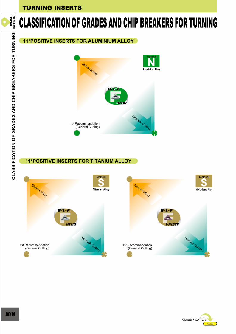
11°POSITIVE INSERTS FOR ALUMINIUM ALLOY
11°POSITIVE INSERTS FOR TITANIUM ALLOY
Material
Aluminium Alloy
Material
Ni, Co-Based Alloy
Material
Titanium Alloy
CLASSIFICATION OF GRADES AND CHIP BREAKERS FOR TURNING
C L A S S I F I C A T I O N O F G R A D E S
A N D C H I P B R E A K E R S F O R T U R N I N G
S t a b l e C u t t i n g
S t a b l e C u t t i n g
S t a b l e C u t t i n g
1st Recommendation(General Cutting)
1st Recommendation(General Cutting)
1st Recommendation(General Cutting)
U n s t a b l e C u t t i n g
U n s t a b l e C u t t i n g
U n s t a b l e C u t t i n g
CLASSIFICATION
T U R N I N G
I N S E R T S
Page 16
7/25/2019 Mitsu Turning Tools Insert Guide
http://slidepdf.com/reader/full/mitsu-turning-tools-insert-guide 16/110
A015
FS
F
K
R/L
SR
SS
SN
FS
F
R/L
R/L
FS
F
K
R/L
SN
SS
FS
FSR
y y
yy
D e p t h o f C u t ( m m )
D e p t h o f C u t ( m m )
Feed (mm/rev)
Breaker
Breaker
Breaker
Breaker
ANGULAR AND PARALLEL CHIP BREAKERS (NEGATIVE INSERTS)
CHIP CONTROL RANGE FEATURES OF CHIP BREAKER
Breaker Features DNGG Type SNGG Type TNGG Type VNGG Type
aa
a
a
a
a
a
a
a
a
For precision finishing.Small width lead breaker for good chip control.Sharp cutting edge gives agood surface finish.
Finish cutting.Lead breaker controlschip flow.Sharp cutting edge gives agood surface finish.
Parallel breaker for lightcutting.Excellent chip control forlow to medium feed rates.
Parallel breaker for mediumcutting.Good chip control for
medium feed rates.
FEATURES OF CHIP BREAKER
Breaker Features CCGT TypeCCET Type DCET Type DCGT Type VBET Type
a
a
a
a
a
a
The wide lead breakerfor medium cutting issuitable for automaticlathe machining.The insert designfor low resistancecontrols chip flow.
The parallel breakerfor light cutting issuitable for automaticlathe machining.Excellent chipcontrol at lowfeed rates.
The parallel breakerfor general purpose issuitable for automaticlathe machining.Excellent chipcontrol for low tomedium feed rates.
Feed (mm/rev)
Standard
Breaker
Breaker
Breaker
Breaker
Breaker Breaker
ANGULAR AND PARALLEL CHIP BREAKERS (POSITIVE INSERTS)
CHIP CONTROL RANGE
Breaker Features CPGT Type DCGT Type TPGH Type TPGV/TPGTType VBGT/VCGTTypeCCGH/CCGTType TCGT Type WBGT Type WCGT Type WPGT Type
a
a
a
a
a
a
a
a
a
a
Precision finishing.Small width lead breakerfor excellent chip control.Sharp cutting edge givesa good surface finish.
Finish cutting.Lead breaker controlschip flow.Sharp cutting edge givesa good surface finish.
Lead breaker for lightcutting.Good chip control for lowto medium feed rates.
For light cutting.Good chip control for lowto medium feed rates.
P R E C I S I O N B R E A K E
R S Y S T E M
PRECISION BREAKER SYSTEM
Standard
T U R N I N G
I N S E R T S
Page 17
7/25/2019 Mitsu Turning Tools Insert Guide
http://slidepdf.com/reader/full/mitsu-turning-tools-insert-guide 17/110
016
10
20
30
40
0.2 0.4 0.6 0.80 0
Rz(W)=Rz×0.5
a
ya
a
a
yy
yy
y
y
10
20
30
40
0.1 0.2 0.3 0.4 0.5 0.6
0
MW(93°)
MW(91°)
Finished surfaceSame surface
roughness
<Cutting Conditions>
Workpiece : DIN Ck45
Insert : CNMG120408-oo
Cutting Speed=200m/min
Depth of Cut=1.5mm
Feed Speed=0.2 –0.6mm/revWet Outer Diameter Cutting
SurfaceRoughne
ss
Rz(m)
Standard Insert
Wiper Insert
MW Breaker
Feed f (mm/rev)
End Cutting
Angle
95°
End Cutting
Angle
75°
The CNMG type canbe used as a wiper atthe 100°corner.
Ex):Theoretical surface roughness of holders when using the TNMX160412-MW.
Feed f (mm/rev)
Theoretic
alSurface
Roughn
ess
Rz(m)
Standardnose radius
End Cutting Angle
Standard noseradius
Wiper
nose radius
<Example of insert point>
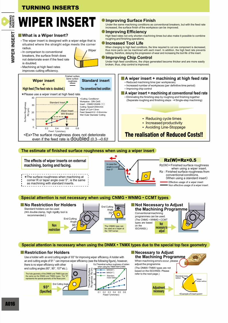
Improving Surface Finish
What is a Wiper Insert?Improving Efficiency
Increased Tool Life
Improving Chip Control
Under the same machining conditions as conventional breakers, but with the feed rateincreased, the surface finish of the workpiece can be improved.
High feed rates not only shorten machining times but also make it possible to combineroughing and finishing operations.
When changing to high feed conditions, the time required to cut one component is decreased,thus more parts can be machined with each insert. In addition, the high feed rate preventsrubbing, therefore, delaying the progression of wear and increasing the tool life of the insert.
Under high feed conditions, the chips generated become thicker and are more easilybroken, thus, chip control is improved.
• The wiper insert is designed with a wiper edge that is
situated where the straight edge meets the corner
radius.
• In comparison to conventional
breakers, the surface finish doesnot deteriorate even if the feed rate
is doubled.
• Machining at high feed rates
improves cutting efficiency.
Adjustmentnecessary
Necessary to Adjustthe Machining ProgrammeWhen machining errors occur, please
adjust the programme.
(The DNMX •TNMX types are not
based on the ISO/ANSI. Please
refer to the next page.)
Special attention is necessary when using the DNMX • TNMX types due to the special top face geometry
Restriction for Holders
93°(Specified)
Use a holder with an end cutting angle of 93° for improving wiper efficiency. A holder with
an end cutting angle of 91 ° can improve wiper efficiency (see the following figure), however,
there is no wiper efficiency with other
end cutting angles (60°, 90°, 107°etc.).
The hole geometry of the DNMX and TNMX type arethe same as the DNMG and TNMG types. The "X"represents the special geometry of the Nose point.
Not Necessary to Adjustthe Machining ProgrammeConventional machining
programmes can be used.
Notnecessary to adjust
(The CNMG • WNMG • CCMT
types are based
on theISO/ANSI.)
No Restriction for HoldersStandard holders can be used.
(* A double clamp, high rigidity tool is
recommended.)
Nonrestriction
Special attention is not necessary when using CNMG • WNMG • CCMT types
In case the
angle is over
than 5°
The effects of wiper inserts on externalmachining, boring and facing.
*The surface roughness when machining atcorner R or taper angle over 5°, is the sameas machining with standard inserts.
The estimate of finished surface roughness when using a wiper insert
<Ex>The surface roughness does not deteriorateeven if the feed rate is doubled (0.30.6)!
• Reducing cycle times • Increased productivity • Avoiding Line-Stoppage
A wiper insert + machining at high feed rate
A wiper insert + machining at conventional feed rate
• Reduced machining time (per workpieces)
• Increased number of workpieces (per definitive time period)
• Improving chip control
• Eliminating the finishing step by roughing and finishing together
(Separate roughing and finishing steps | Single-step machining)
Wiper insert+
High feed (The feed rate is doubled.)
Standard insert+
The conventional feed condition
*Please use a wiper insert at high feed rate.
The realisation of Reduced Costs!!
W I P
E R I N S E R T
TURNING INSERTS
WIPER INSERT
Effective usage of a wiper insert
Non effective usage of a wiper insert
Rz(W)=Finished surface roughness
when using a wiper insert.Rz : Finished surface roughness from
conventional conditions.(When using a standard insert)
Wiper
T U R N I N G
I N S E R T S
Page 18
7/25/2019 Mitsu Turning Tools Insert Guide
http://slidepdf.com/reader/full/mitsu-turning-tools-insert-guide 18/110
A017
1.2
0.8
0.4
90
0
0
0
0.01
0.01
00
0
00
0.01 -0.01
-0.01
-0.01 -0.01
0.02
0.02
0.01
0.04
0.03
0.01
0.04
0.03
0.02
0.05
0.04
0.02
0.04
0.03
0.02
0.04
0.03
0.02
0.03
0.02
0.01
0.03
0.02
0.01
0.02
0.01
0.01
0.01
0.01
0.01
0
0
0
0
75 857060 655550454020 3515105-5-10-25 -15
R2.0
R 1 . 2
R2.0
R
1 . 1 6
R 1 . 2
R 1 . 2
=2.0+0.14
R2.14 0 . 0 5
'° ( - )
'° ( + )
0.040.05
::
0.01
Ex): In the case of machining a corner with a radius R 2.0 when usingan insert with a nose radius R 1.2.
Ex) : In case of machining R 2.0 when using a nose R 1.2 type insert.
Geometry of adjusted
programme
Workpieceradius 2.0
The actual machininggeometry
Work radius Adjusted conditionsWorkpieceradius 2.0
Nose radius
Taper Angle '°
Geometry of
adjusted program
T h e d
e p t h
o f
o v e r
c u t
T h e d e
p t h o f
o v e r
c u t
The actual machininggeometry
(Not closed to Nose R)
Standard insert
DNMX,TNMXtype
Standard insert
Nose radius 0.4,0.8Nose radius 1.2
DNMX,TNMXtype
Adjustment of machining programmes for DNMX • TNMX types
Basic Process) Adjusting Toward X-axis and Z-axis Adjusting the differential between a standard insert and Z-axis / X-axis.
Adjustment toward X-axis
Adjustment toward Z-axis
Adjust the relief angle toward the normal line.
Classification
A) Adjusting a Taper *Necessary to maintain a correct taper.
Note) Adjust the angle toward the normal line in the case where the
adjustment number is minus ( ' =60°70°) and is not machined completely.
The number+numbers:adjustment of relief angle, -numbers:adjustment of drive-in angle (mm)
B) Adjusting a Corner R *Necessary to maintain a correct corner radius.
Adjust the work diameter to the same as the taper to prevent over-cut.
The nose radiusof the insert
The adjustment amount on theworkpiece radius.
The value of adjustment to workpiece R= Workpiece R + the adjustment value
*No adjusting of the nose radius in this case.
Nose Radius 0.4 |
Nose Radius 0.8 |
Nose Radius 1.2 |
Work Radius+0.05(mm)
Work Radius
Work Radius
+0.11(mm)
+0.14(mm)
The Easy-to-correct Method
In correcting nose radius:It is not necessary to adjust the machining programme, however, machining errors can occur within max.±0.03mm due to correcting by an approximate number.
Nose Radius Correction Input the correction number of each nose radius.
The nose radiusof the insert
Nose Radius 0.4 |
Nose Radius 0.8 |
Nose Radius 1.2 |
R0.36(mm)
R0.76(mm)
R1.16(mm)
The value of correctednose radius = approximation
Others) The value of correction is same for both DNMX and TNMX. Discriminate them by the size of nose radius.
The value of corrected nose radius= approximation
*No need to adjust the programme in this case.
W I P
E R I N S E R T
T U R N I N G
I N S E R T S
mmmm
mm
Page 19
7/25/2019 Mitsu Turning Tools Insert Guide
http://slidepdf.com/reader/full/mitsu-turning-tools-insert-guide 19/110
Page 20
7/25/2019 Mitsu Turning Tools Insert Guide
http://slidepdf.com/reader/full/mitsu-turning-tools-insert-guide 20/110
A019
0
100
200
300
400
0 0.2 0.4 0.6 0.8 0 0.2
100
200
300
400
0.4 0.6 0.8
0 0.2
100
200
300
400
0.4 0.6 0.8 0 0.1
200
400
600
800
0.2 0.3 0.4
MP
NK
UP35N
UC6010
US7020
UE6020
UE6035
AP25NVP25NNX2525
US7020
US735
UTi20T
VP15TFVP20MF
VP45N
U5735UH6400
UTi20T
AP25N
VP25N
NX2525
UC5105
HTi10
NX2525
NX3035
VP15TFUP20M
VP15TF
HTi05THTi10
UTi20T
AP25N
VP25N
MB710
MB730
UC5115
MD220
UE6110
UC5115 UE6005
MBS140
Cermet and Coated Cermet
CVD Coated Carbide
PVD Coated Carbide
Cemented Carbide
Cermet and Coated Cermet
CVD • PVD Coated Carbide
Cemented Carbide
Sintered CBN
Solid CBN
Cermet and Coated Cermet
PVD Coated Carbide
Cemented Carbide
Cemented Carbide
Sintered Diamond
CVD Coated Carbide
NON-FERROUS METALCAST IRON
STAINLESS STEELSTEEL
Feed (mm/rev)
C u t t i n g S p e e d ( m / m i n )
C u t t i n g S p e e d ( m / m i n )
Feed (mm/rev)
C u t t i n g
S p e e d ( m / m i n )
C u t t i n g
S p e e d ( m / m i n )
Feed (mm/rev) Feed (mm/rev)
TURNING APPLICATION RANGE
T U R N I N G A P P L I C A T I O N R A N G E
T U R N I N G
I N S E R T S
Page 21
7/25/2019 Mitsu Turning Tools Insert Guide
http://slidepdf.com/reader/full/mitsu-turning-tools-insert-guide 21/110
020
FH
AP25N
FH
UE6110
MV
UE6005
SH
UE6005
SH
UE6020
HX
UE6110
GH
UE6005
HX
UH6400
GH
UE6020
MV
UE6020
MV V
UE6010 E6010
SH H
UE6010 E6010
FH H
AP25N P N
MV
UE6110
SH
UE6110
FH
NX3035
HX X
UE6020 E6020
GH H
UE6010 E6010
HX
UE6020
GH
UE6110
y y
S01
M10
M20
M30
M40
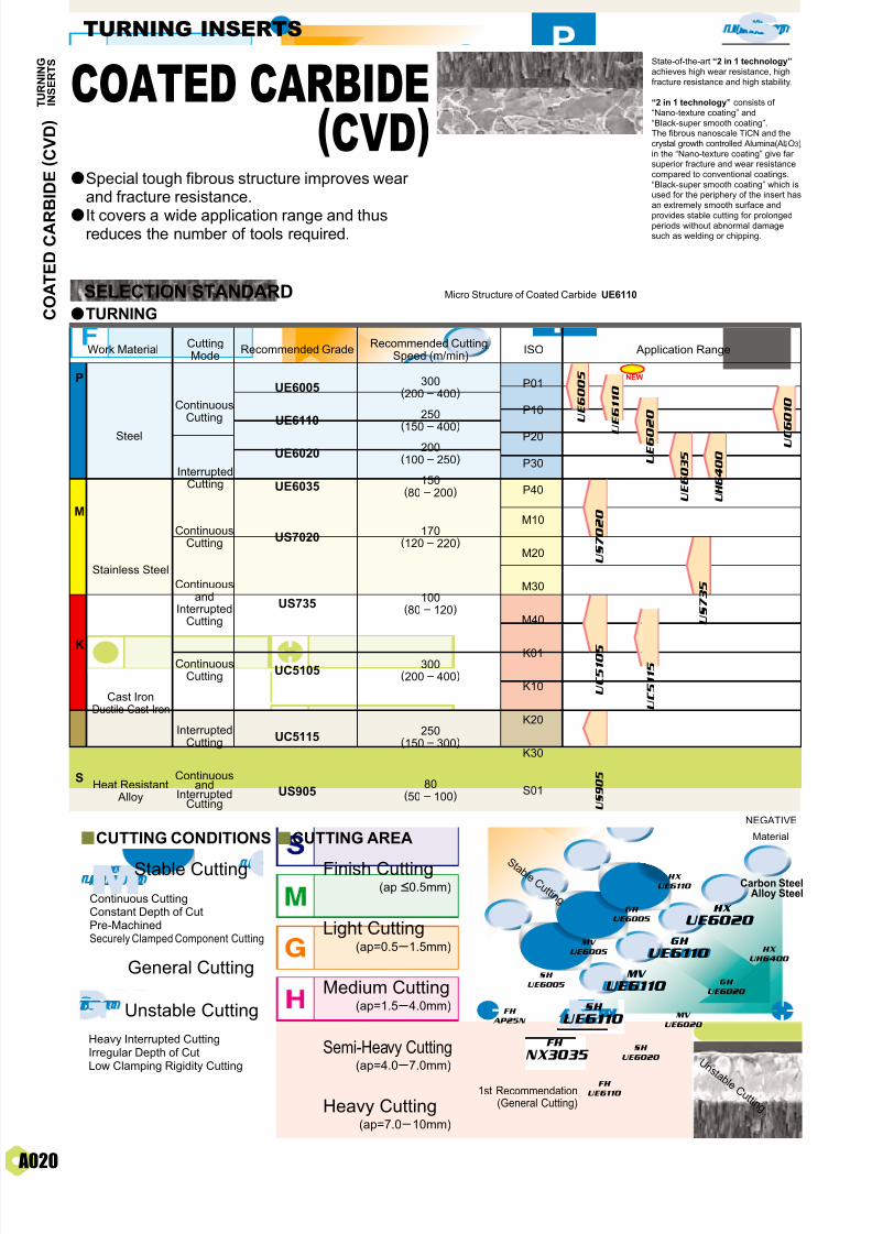
US7020
US735
170(120 – 220)
100(80 – 120)
UE6005 P01
P10
P20
P30
P40
K01
K10
K20
K30
UE6110
UE6020
UE6035
UC5105
UC5115
US905
300(200 – 400)
250
(150 – 400)200
(100 – 250)
150(80 – 200)
300(200 – 400)
250(150 – 300)
80(50 – 100)
S
K
P
M
NEW
U S 9 0 5
U S 7 0 2 0
U S 7 3 5
U E 6 0 0 5
U
E 6 1 1 0
U E 6 0 2 0
U E 6 0 3 5
U H 6 4 0 0
U C 6
0 1 0
U C 5 1 0 5
U C 5 1 1 5
TURNING INSERTS
SELECTION STANDARD Micro Structure of Coated Carbide UE6110
CUTTING CONDITIONS
Stable Cutting
General Cutting
Unstable Cutting
Continuous CuttingConstant Depth of CutPre-MachinedSecurely Clamped Component Cutting
Heavy Interrupted CuttingIrregular Depth of CutLow Clamping Rigidity Cutting
Finish Cutting(ap <0.5mm)
Light Cutting(ap=0.5 1.5mm)
Medium Cutting(ap=1.5 4.0mm)
Heavy Cutting(ap=7.0 10mm)
Semi-Heavy Cutting(ap=4.0 7.0mm)
CUTTING AREA
State-of-the-art “2 in 1 technology”
achieves high wear resistance, high
fracture resistance and high stability.
“2 in 1 technology” consists of
“Nano-texture coating” and
“Black-super smooth coating”.The fibrous nanoscale TiCN and the
crystal growth controlled Alumina(Al2O3)
in the “Nano-texture coating” give farsuperior fracture and wear resistance
compared to conventional coatings.
“Black-super smooth coating” which isused for the periphery of the insert has
an extremely smooth surface and
provides stable cutting for prolongedperiods without abnormal damagesuch as welding or chipping.
Continuousand
InterruptedCutting
Continuousand
InterruptedCutting
ContinuousCutting
Stainless Steel
Steel
ContinuousCutting
InterruptedCutting
InterruptedCutting
ContinuousCutting
Cast IronDuctile Cast Iron
Heat Resistant Alloy
aTURNING
Special tough fibrous structure improves wearand fracture resistance.
It covers a wide application range and thusreduces the number of tools required.
Material
NEGATIVE
Work MaterialCuttingMode
Recommended GradeRecommended Cutting
Speed (m/min) Application RangeISO
C O A T E D C A R
B I D E ( C V D )
COATED CARBIDE(CVD)
S t a b l e C u t t i n g
1st Recommendation (General Cutting)
U n
s t a b l e C u t t i n g
a
a
Carbon SteelAlloy Steel
T U R N I N G
I N S E R T S
Page 22
7/25/2019 Mitsu Turning Tools Insert Guide
http://slidepdf.com/reader/full/mitsu-turning-tools-insert-guide 22/110
A021
UE6005
UC6010
UE6020
UE6035
US7020
US735
91.0
90.5
90.0
89.5
90.5
89.0
1.8
UE6110 90.3 2.0
2.0
2.2
2.3
UH6400 89.5 2.3
2.0
2.6
UC5105 92.2 2.0
UC5115 91.0 2.2
FS
NX2525
FS
NX2525
MS
US7020
SH
US735
SH
US735
HL
UE6020
GH
US7020
HL
UE6020
GH
US735
MS
US735
MA
UC5105
UC5105
UC5105
R/L-F
NX2525
MA
UC5115
UC5115
UC5115
R/L-FNX2525
MS
US735
SH
US735
FS
NX2525
MA
UC5115
UC5115
R/L-F
NX2525
HL
UE6020
GH
US735
UC5115
US905 92.2 2.0
210
0.3
3.0
160
0.25
2.0
WNMG080408-MV(UE6020)CNMG120416-MA(UE6110)
0.15 0.2
2
250
0.30
2.5
CNMA120408(UC5105)CNMG120408-MS(US7020)
2010
UE6110 UE6020
50 100
US7020
40 80
UC5105
250 500
GRADE CHARACTERISTICS
APPLICATION EXAMPLES
Grade
Tough
TiCN-AI2O3 Thick
TiCN-AI2O3 Thick
Thick
Thick
Thick
Thick
Thin
Thin
TiCN-AI2O3-TiN
Tough Thick Accumulated TiCN-Al2O3-Ti Compound
TiCN-AI2O3-TiN
Accumulated TiCN-Al2O3-Ti Compound
TiCN-AI2O3-TiN
TiCN-AI2O3-TiN
Ti Compound
ThinTiCN-AI2O3
* 1GPa=102kg/mm2
Tough
Tough
Tough
Thick Accumulated TiCN-Al2O3-Ti CompoundTough
Tough
Wet cutting Wet cutting
Alloy steel(DIN 41CrMo4)
Alloy steel
Hardness (HRA)
Cutting Speed (m/min)
Feed (mm/rev)
Depth of Cut (mm)
Coolant
Cutting Speed (m/min)
Feed (mm/rev)
Depth of Cut (mm)
Coolant
T.R.S (GPa) Surface Composition
Insert (Grade)
Workpiece
Result
Substrate Coating Layer
Thickness
pieces/corner pieces/corner
Competitor's P20 coatingCompetitor's P10 coating
UE6020 achieved 6 times longer tool life.
Wet cutting
Conventional coated grade=100, US7020=200
Wet cutting
Stainless steel(DIN X5CrNiMo1810)
Gray cast iron(DIN GG30)
Insert (Grade)
Workpiece
Result
pieces/corner
UC5105 achieved more than double tool life.
UE6110 achieved more than double tool life.
US7020 achieved two times longer tool life comparedto previous grade when turning at double cutting speed.
Previous coated grade
pieces/corner
Competitor's K01 coating Large wear
Material
NEGATIVE
Material
NEGATIVE
Flat Top
Standard
Standard
Flat Top
C O A T E D C A R
B I D E ( C V D )
S t a b l e C u t t i n g
U n s t a b l e C u t t i n g
S t a b l e C u t t i n g
U n s t a b l e C u t t i n g
1st Recommendation (General Cutting)
1st Recommendation (General Cutting)
Flat Top
Standard
C u t t i n g
C o n d i t i o n s
C u t t i n g
C o n d i t i o n s
Stainless Steel C a s t I r o n
T U R N I N G
I N S E R T S
Page 23
7/25/2019 Mitsu Turning Tools Insert Guide
http://slidepdf.com/reader/full/mitsu-turning-tools-insert-guide 23/110
022
S01
S10
S20
S30
VP 15 TF
K
S
P
M
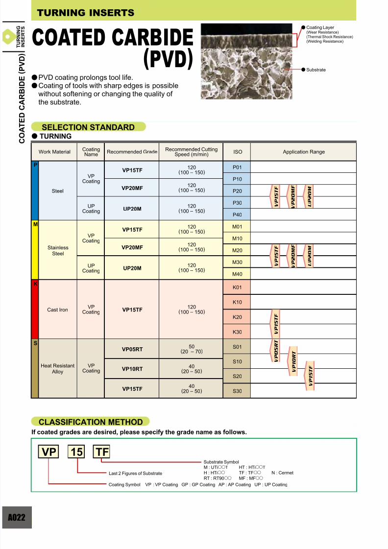
VP15TFP01
P10
P20
P30
P40
VP20MF
UP20M
120(100 – 150)
120
(100 – 150)
120(100 – 150)
VP15TFM01
M10
M20
M30
K01
K10
K20
K30
M40
VP20MF
UP20M
120(100 – 150)
120(100 – 150)
120(100 – 150)
VP15TF120
(100 – 150)
VP05RT
VP10RT
VP15TF
50(20 – 70)
40(20 – 50)
40(20 – 50)
a
V P 0 5 R T
V P 1 0 R T
V P 1 5 T F
V P 2 0 M
F
U P 2 0 M
V P 1 5 T
F
V P 1 5 T F
V P 2 0 M F
U P 2 0 M
V P 1 5 T F
a
a
TURNING INSERTS
PVD coating prolongs tool life.Coating of tools with sharp edges is possible
without softening or changing the quality of the substrate.
Coating Layer(Wear Resistance)
(Thermal Shock Resistance)(Welding Resistance)
Substrate
SELECTION STANDARDTURNING
Work Material Recommended GradeRecommended Cutting
Speed (m/min)CoatingName
Steel
VPCoating
UPCoating
VPCoating
UPCoating
Cast IronVP
Coating
StainlessSteel
ISO
Heat Resistant Alloy
VPCoating
CLASSIFICATION METHODIf coated grades are desired, please specify the grade name as follows.
Substrate Symbol
Last 2 Figures of Substrate
Coating Symbol VP : VP Coating GP : GP Coating AP : AP Coating UP : UP Coating
M : UTiooT HT : HTiooT
H : HTioo TF : TFoo N : Cermet
RT : RT90oo MF : MFoo
Application Range
C O A T E D C A R B I D E ( P V D )
COATED CARBIDE(PVD)
T U R N I N G
I N S E R T S
a
a
Page 24
7/25/2019 Mitsu Turning Tools Insert Guide
http://slidepdf.com/reader/full/mitsu-turning-tools-insert-guide 24/110
A023
900
(r)
800
700
600
50 60 70 80 (N)
ø 4 5
ø 8 5
ø 4 5
ø 3 6
ø 5 0
8004000
300150750210
15005000
170
0.14
0.25
200
0.25
0.5
CNMG120408-MJ(VP10RT)DCMT11T304-MV(VP15TF)
31
0.2
2.3
120
0.05
0.5
TNMG160408-MJ(VP05RT)CNMG120408-GJ(VP10RT)
VP15TF
Compared to conventional coating technology, VP
(MIRACLE) coating features (Al, Ti) N coating with highly
increased heat resistance and adhesion strength.
FEATURES OF VP (MIRACLE) COATING
O x i d a t i o n T e m p e r a t u r e
Adhesion Strength
Increased Heat Resistance
Increased Adhesion Strength
Competitor's Coating Grade
MIRACLE Coating
Competitor'sP30 coating
APPLICATION EXAMPLES
Wet cutting Wet cutting
Alloy steel Stainless Steel (Fan parts)
Cutting Speed (m/min)
Feed (mm/rev)
Depth of Cut (mm)
Coolant
Cutting Speed (m/min)
Feed (mm/rev)
Depth of Cut (mm)
Coolant
Insert (Grade)
Workpiece
Result
pieces/corner pieces/corner
Competitor's K20 carbide(M Class)
pieces/corner pieces/corner
Competitor's K10 carbide
(G Class)
Competitor's
coated carbide
Wet cutting Wet cutting
Inconel 718 (Pin) Sintered iron parts (FH655)
Insert (Grade)
Workpiece
Result
C u t t i n g
C o n d i t i o n s
C u t t i n g
C o n d i t i o n s
VP15TF does not experience chipping.This enables stable machining and much longer tool life.
MJ breaker achieved 1.5 times longer tool life.
MJ breaker achieved 5 times longer tool life.VP10RT achieved 4 times longer tool life.GJ breaker for excellent chip disposal and vastlyincreased tool life.
C O A T E D C A R
B I D E ( P V D )
(VP10RT)
(VP10RT)
M Class
(VP05RT)
M Class
T U R N I N G
I N S E R T S
GJ
MJ
MJ breaker
breaker
breaker
Page 25
7/25/2019 Mitsu Turning Tools Insert Guide
http://slidepdf.com/reader/full/mitsu-turning-tools-insert-guide 25/110
024
NX2525
NX3035
NX2525
K01
K10
K20
P01
P10
P20
210(170 230)
230(190 260)
250(200 280)
NX2525
NX55
NX99
92.2
91.7
91.2
2.0
1.8
1.9
33
25
33
7.8
NX3035 91.5 2.1 35 7.8
7.8
7.8
K
P
y y
y
NEW
N X 2 5 2 5
N X 3 0 3 5
N X 5 5
N X 2 5 2 5
N X 9 9
NX3035
0 5 10 15 20 25 30 35
0.05
0.10
0.15
0.20
0.25
0.30
0.35
30252015105
0.1
0.05
0
0 500 1,000 1,500 2,000
NX2525
NX3035
TURNING INSERTS
SELECTION STANDARDaTURNING
Micro-Structure of NX2525
a
<Cutting Conditions>
Workpiece : DIN Ck45
Insert : CNMG120408-pp
vc=250m/min
ap=1.0mm
f=0.15mm/rev
Wet Cutting
External Continuous Cutting
<Cutting Conditions>Workpiece : DIN GG30
Insert : CNMG120408
vc=100m/minap=1.5mm
f=0.3mm/rev
Wet Cutting
* 1GPa=102kg/mm2, 1W/m • K=2.39×10⁻³cal/cm • sec •r
CUTTING PERFORMANCE
GRADE CHARACTERISTICS
Steel
Cast IronDuctile Cast Iron
<Cutting Conditions>
Workpiece : DIN 41CrMo4
Insert : CNMG120408-pp
vc=200m/min
ap=1.5mm
f=0.2mm/rev
Wet Cutting
Interrupted Cutting
Cutting Performance
Hardness (HRA) T.R.S (GPa) Thermal Conductivity(W/m • K)
Thermal Expansion(×10-6/K)
Grade
Substrate
Cutting Time (min)
F l a n k W e a r ( m m )
Competitor's K10Cemented Carbide
Cutting Time (min)
F l a n k
W e a r ( m m )
Steel, Continuous Cutting (Wet)
Cast Iron, Continuous Cutting
NX2525 has high
hardened Ti compound
particles within it's
microstructure therefore
the grade has bothexcellent wear and fracture
resistance properties.
Micro-Structure of NX3035
aNX3035 uses a special
alloy substrate in the metal
binder phase to deliver
highly improved thermal
shock resistance.
*
Competitor's P20coated cermet
Competitor'smicro grainP20 cermet
Cutting Time (min) Number of Impacts
Competitor'smicro grainP20 cermet
Competitor'sP20 coatedcermet
ContinuousCutting
InterruptedCutting
Finishing
Work MaterialCuttingMode
Recommended GradeRecommended Cutting
Speed (m/min) Application RangeISO
Cutting Speed : vc Depth of Cut : apFeed : f
C E R M E T
CERMETa
a
a
a
The optimized alloy structure and special alloy binderimproves both wear and fracture resistance.It covers a wide application range and reduces thenumber of tools required.NX3035 for wet cutting.
NX2525 for dry cutting.
T U R N I N G
I N S E R T S
Steel, Interrupted Cutting
Page 26
7/25/2019 Mitsu Turning Tools Insert Guide
http://slidepdf.com/reader/full/mitsu-turning-tools-insert-guide 26/110
A025
AP25N
AP25N
P01
P10
P20
P30
K01
K10
K20
UP35N
VP45N
220(170 250)
180
(140 200)
280(200 320)
K
P
0.18 0.20 0.22 0.24 0.26
10002000
10002000
10002000
10002000
10002000
yy
y
V P 2 5 N
U P 3 5 N
V P
4 5 N
A P 2 5 N
V P 2 5 N
A P 2 5 N
50
100
5 10 15 20
0.1
0.2
0.3
AP25N
AP25N
UP35N
aCoated cermet (PVD coating) has superior wear andfracture resistance, and therefore provides a stablecutting performance.
Micro-Structure of AP25N
a
a
SubstrateMicro Grain Cermet NX2525(wear resistance and fracture
resistance)
Coating Layer Outer layer is TiN
(Welding resistance)
Middle layer is(Ti, Al) N Compound.
(wear resistance thermal
shock resistance)
N u m b e r o f P a s s e s
<Cutting Conditions>
Workpiece : DIN 41CrMo4 (HB230)
Insert : CNMG120408-pp
vc=200m/min
ap=2.0mm
f=0.3mm/rev
Wet Cutting
Competitor's
PVD
Cermet A
Conventional
Cermet
SELECTION STANDARDaTURNING
Steel
Cast IronDuctile Cast Iron
CUTTING PERFORMANCE
F l a n k W e a r ( m m )
<Cutting Conditions>
Workpiece : DIN 41CrMo4 (HB230)
Insert : CNMG120408-pp
vc=300m/min
ap=0.5mm
f=0.2mm/rev
Wet Cutting
ConventionalCermet
Competitor'sPVD Cermet A
Cutting Time (min)
<Cutting Conditions>
Workpiece : DIN 41CrMo4 (HB230)
Insert : CNMG120408-MA
vc=200m/min
ap=1.5mm
Dry Cutting
Normal Wear
Chipping
Cutting Performance
Wear Resistance for Wet Cutting
Fracture Resistance for Interrupted Cutting
Thermal Shock Resistance for Interrputed Cutting
Work MaterialCuttingMode
Recommended GradeRecommended Cutting
Speed (m/min) Application RangeISO
ContinuousCutting
Interrupted
Cutting
Finishing
Feed(mm/rev)
No. ofImpacts
ConventionalCermet
Cutting Speed : vc Depth of Cut : apFeed : f
C O A T E
D C E R M E T
COATED CERMET T
U R N I N G
I N S E R T S
Page 27
7/25/2019 Mitsu Turning Tools Insert Guide
http://slidepdf.com/reader/full/mitsu-turning-tools-insert-guide 27/110
026
P M
KN
N
P
K
M
S
S
M
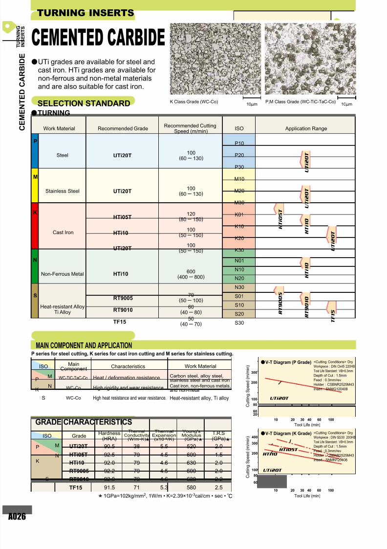
UTi20T
UTi20T
HTi05T
HTi10
UTi20T
HTi10 600(400 800)
60(40 80)
50(40 70)
70(50 100)
100(60 130)
120(80 150)
100(50 150)
100(50 150)
RT9010
RT9005
TF15
P10
P20
P30
M10
M20
M30
K01
K10
K20
K30
P
K
N
S
N01
N10
N20
N30
S01
S10
S20
S30
100(60 130)
UTi20T
HTi05T
HTi10
RT9005
RT9010
TF15
90.5
92.5
92.0
92.2
92.0
91.5
38
79
79
79
79
71
5.5
4.5
4.6
4.5
4.6
5.3
520
600
630
600
630
580
2.0
1.5
2.0
2.0
2.2
2.5
WC-Co
WC-TiC-TaC-Co
WC-Co
U T i 2 0 T
U T i 2 0 T
R T 9 0 0 5
300
200
100
80
6020
10 20 30 40 60 100
UTi20T
300
200
100
80
60
10 20 30 40 60 100
400
UTi20T
HTi10
HTi05T
H T i 1 0
T F 1 5
R T 9 0 1 0
H T i 0 5 T
H T i 1 0
U T i 2 0 T
Heat-resistant alloy, Ti alloyHigh heat resistance and wear resistance.
TURNING INSERTS
UTi grades are available for steel andcast iron. HTi grades are available fornon-ferrous and non-metal materialsand are also suitable for cast iron.
SELECTION STANDARD 10!m 10!mP,M Class Grade (WC-TiC-TaC-Co)K Class Grade (WC-Co)
MAIN COMPONENT AND APPLICATION
GRADE CHARACTERISTICS
P series for steel cutting, K series for cast iron cutting and M series for stainless cutting.
Steel
Cast Iron
Stainless Steel
Non-Ferrous Metal
Heat-resistant AlloyTi Alloy
Heat / deformation resistance.
High rigidity and wear resistance.
Carbon steel, alloy steel,stainless steel and cast iron
Tool Life (min)
C u t t i n g S p e e d
( m / m i n )
a <Cutting Conditions> Dry
Workpiece : DIN Ck45 220HB
Tool Life Standard : VB=0.3mm
Depth of Cut : 1.5mm
Feed : 0.3mm/rev
Holder : CSBNR2525M43
Insert : SNMG120408
Tool Life (min)
C u t t i n g S p e e d ( m / m i n )
a
V-T Diagram (P Grade)
V-T Diagram (K Grade) <Cutting Conditions> Dry
Workpiece : DIN GG30 200HB
Tool Life Standard : VB=0.3mm
Depth of Cut : 1.5mm
Feed : 0.3mm/rev
Holder : CSBNR2525M43
Insert : SNMN120408
* 1GPa=102kg/mm2, 1W/m • K=2.39×10⁻³cal/cm • sec • r
Work Material
MainComponent Characteristics
Recommended GradeRecommended Cutting
Speed (m/min) Application RangeISO
ISO
ISOHardness
(HRA)Grade
ThermalConductivity
(W/m•K)
ThermalExpansion(x10-6/K)
Young'sModulus(GPa)
T.R.S(GPa)
Cast iron, non-ferrous metals,and non-metal
C E M E N T E D C A R B I D E
CEMENTED CARBIDE
* * *
T U R N I N G
I N S E R T S
Work Material
aTURNING
a
Page 28
7/25/2019 Mitsu Turning Tools Insert Guide
http://slidepdf.com/reader/full/mitsu-turning-tools-insert-guide 28/110
Page 29
7/25/2019 Mitsu Turning Tools Insert Guide
http://slidepdf.com/reader/full/mitsu-turning-tools-insert-guide 29/110
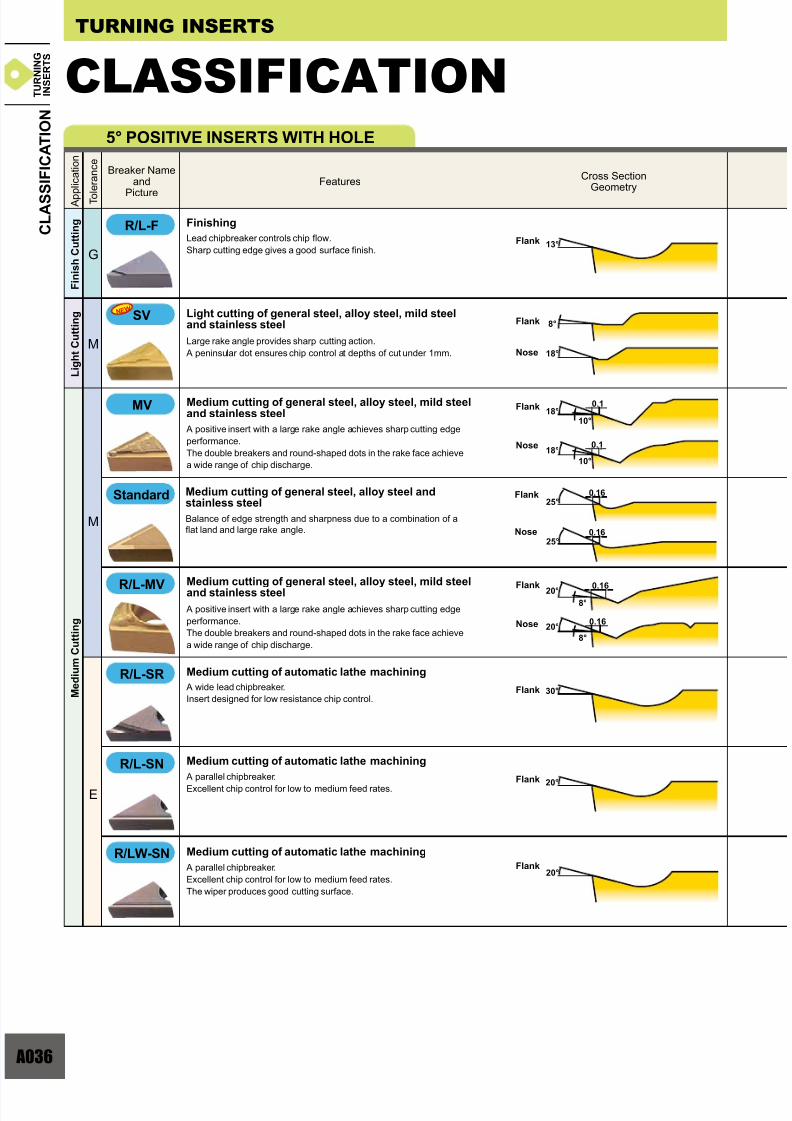
028
12°
12°
8°
9°
16°
15°0.2
15°
14°
15°
15°
14°
0.3
0.34
0.2
0.16
7°
8°
25°
10°
25°
15°
18°
0.16
7°
18°
15°
M
G
M
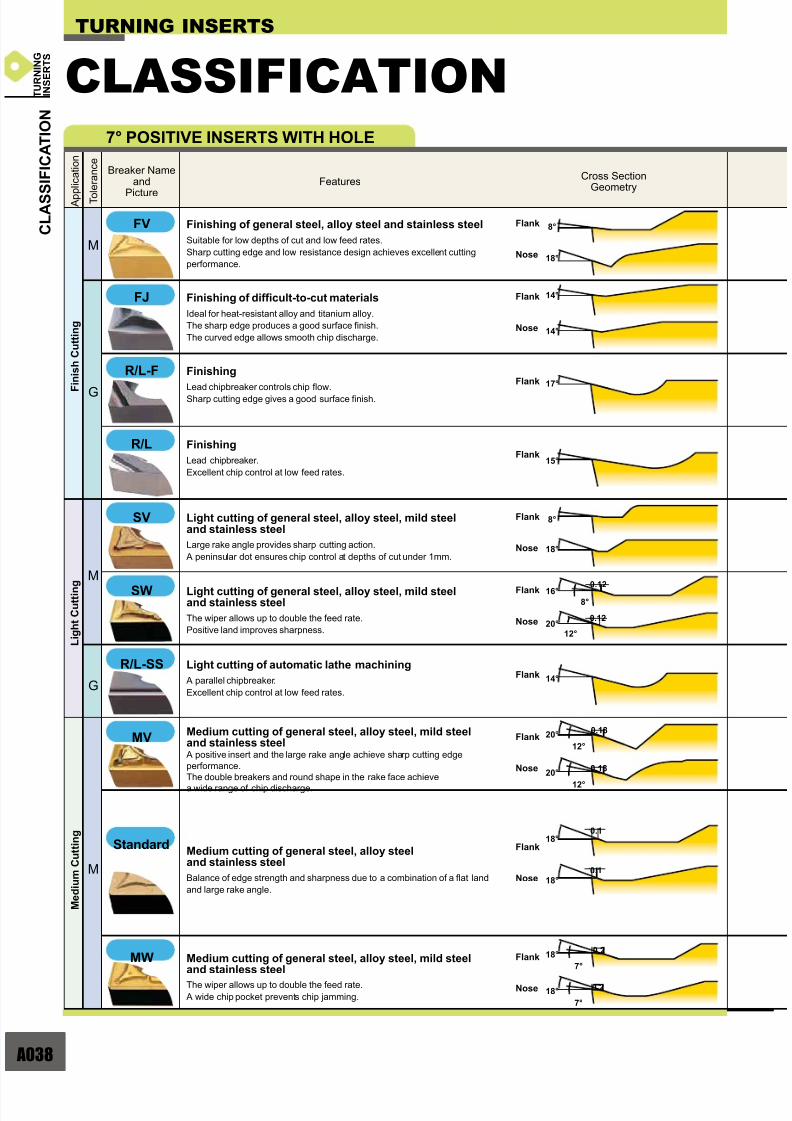
FH
FS
FJ
PK
R/L-F
SH
SA
SW
FY N E W
T U R N I N G
I N S E R T S
Double sided chipbreaker.
Stable chip control even at small depth of cut.
First recommendation for finishing general steel andalloy steel
Double sided chipbreaker.
Stable chip control even at a small depth of cut.
Sharp edge gives best performance.
First recommendation for finishing stainless steelAlternative chipbreaker for finishing mild steel
Double sided chipbreaker.
Effectively controls adhesive chips.
Suitable for mild steel finishing.
First recommendation for finishing mild steel
Double sided chipbreaker.
Ideal for heat-resistant alloy and titanium alloy.
The sharp edge produces good cutting surface.
The curved edge allows smooth chip discharge.
First recommendation for finishing difficult-to-cut materials
Double sided chipbreaker.
G class insert tolerance is suitable for workpieces requiring close
dimensional tolerances.
Stable chip control even at a small depth of cut.
Alternative chipbreaker for finishing general steel and alloy steel
Double sided chipbreaker.
Lead chipbreaker controls chip flow.
The sharp edge produces a good surface finish.
Finishing
Double sided chipbreaker.
Can be used at low depths of cut and high feed rates.
The curved edge allows smooth chip discharge.
Recommended for workpieces in the 160 250HB range.
First recommendation for light cutting of general steel andalloy steel
Double sided chipbreaker.
Superior chip control at small depth of cuts.
Covers copying and back turning with the wavy edge.
Recommended for workpieces in the 200 300HB range.
Alternative chipbreaker for light cutting of general steeland alloy steel
Breaker Nameand
Picture
FeaturesCross Section
Geometry
C L A S S I F I C A T I O N
A p p l i c a t i o n
T o l e r a n c e
NEGATIVE INSERTS WITH HOLE
TURNING INSERTS
CLASSIFICATION
Double sided chipbreaker.
The wiper allows up to double the feed rate.
Wiper design for increased productivity and improved surface finish.
Wiper insert for light cutting of general steel and alloy steel
Flank
Nose
Flank
Nose
Flank
Nose
Flank
Nose
Flank
Flank
Nose
Flank
Nose
Flank
Nose
Flank
Nose
F i n i s h C u t t i n g
L i g h t C u t t i n g
Page 30
7/25/2019 Mitsu Turning Tools Insert Guide
http://slidepdf.com/reader/full/mitsu-turning-tools-insert-guide 30/110
A029
^ A048 ^ A053 ^ A058 ^ A062 ^ A068 ^ A070
FH
FS
FJ
PK
R/L-F
SH
SA
SW
CNMG_FH DNMG_FH SNMG_FH TNMG_FH VNMG_FH WNMG_FH
^ A048 ^ A053 ^ A058 ^ A062 ^ A068 ^ A070
CNMG_FS DNMG_FS SNMG_FS TNMG_FS VNMG_FS WNMG_FS
^ A048 ^ A053 ^ A058 ^ A062 ^ A070
CNMG_FY DNMG_FY SNMG_FY TNMG_FY WNMG_FY
^ A048 ^ A053 ^ A068
CNGG_FJ DNGG_FJ VNGG_FJ
^ A048 ^ A053 ^ A058 ^ A062
CNGG_PK DNGG_PK SNGG_PK TNGG_PK
^ A062
TNGG_R/L-F
^ A048 ^ A053 ^ A058 ^ A062 ^ A068 ^ A070
CNMG_SH DNMG_SH SNMG_SH TNMG_SH VNMG_SH WNMG_SH
^ A049 ^ A054 ^ A058 ^ A063 ^ A070
CNMG_SA DNMG_SA SNMG_SA TNMG_SA WNMG_SA
^ A049 ^ A054 ^ A063 ^ A070
CNMG_SW DNMX_SW TNMX_SW WNMG_SW
FY N E W
T U R N I N G
I N S E R T S
Breaker Nameand
Cross Section
Rhombic 80° Rhombic 55° Square 90° Triangular 60° Rhombic 35° Trigon 80° Round
C L A S S I F I C A T I O N
Page 31
7/25/2019 Mitsu Turning Tools Insert Guide
http://slidepdf.com/reader/full/mitsu-turning-tools-insert-guide 31/110
030
0.2
02
02
0.2
6°
22°
0.26°
22°
0.2
6°
22°
0.2
11°
30°
10°
10°
15°
15°
0.3516°
0.2516°
0.215°
0.2515°
0.319°
0.2519°
0.525°
15°
0.525°
15°
M
M
MV
MA
MH
MW
MS
R/L-1G
SY
R/L-1M
N E W
N E W
T U R N I N G
I N S E R T S
Breaker Nameand
Picture
FeaturesCross Section
Geometry
C L A S S I F I C A T I O N
A p p l i c a t i o n
T o l e r a n c e
NEGATIVE INSERTS WITH HOLE
TURNING INSERTS
CLASSIFICATION
L i g h t C u t t i n g
M e d i u m C u t t i n g
Double sided chipbreaker.
Effectively controls adhesive chips.
Suitable for mild steel light cutting.
First recommendation for light cutting of mild steel
Double sided chipbreaker.
Parallel chipbreaker controls chip flow.
Suitable for finish-light cutting.
Moulded chipbreaker.
Alternative chipbreaker for light cutting of general steeland alloy steel
Double sided chipbreaker.
Parallel chipbreaker controls chip flow.
Suitable for finish-light cutting.
Precision chipbreaker.
Alternative chipbreaker for light cutting of general steeland alloy steel
Double sided chipbreaker.
Suitable for medium to light cutting.
Breaker geometry appropriate for copying and back turning.
Positive land provides sharp cutting action.
First recommendation for medium cutting of general steeland alloy steel
Double sided chipbreaker.
Positive land provides sharp cutting action.
Alternative chipbreaker for medium cutting of general steeland alloy steelFirst recommendation for light cutting cast iron
Double sided chipbreaker.
Flat land offers high edge strength.
Alternative chipbreaker for medium cutting of general steeland alloy steelFirst recommendation for medium - heavy cutting of mild steel
Double sided chipbreaker.
Flat land offers high edge strength.
First recommendation for medium cutting of cast ironAlternative chipbreaker for medium cutting of general steeland alloy steel
Double sided chipbreaker.
The wiper allows up to two times higher feed.
A wide chip pocket prevents chip jamming.
Wiper insert for medium cutting general steel andalloy steel
Double sided chipbreaker.
The sharp edge gives best performance.
First recommendation for medium cutting of stainless steeland mild steelFirst recommendation for semi-heavy cutting of
difficult-to-cut materials
Flank
Nose
Flank
Nose
Flank
Nose
Flank
Nose
Flank
Nose
Flank
Nose
Flank
Flank
Flank
Nose
StandardStandard
Page 32
7/25/2019 Mitsu Turning Tools Insert Guide
http://slidepdf.com/reader/full/mitsu-turning-tools-insert-guide 32/110
A031
^ A049 ^ A054 ^ A058 ^ A063 ^ A070
CNMG_SY DNMG_SY SNMG_SY TNMG_SY WNMG_SY
^ A071
WNMG_MV
^ A071
WNMG_MA
^ A071
WNMG_MH
^ A063
TNMG_R/L-1M
^ A059 ^ A063
SNMG_R/L-1G TNMG_R/L-1G
^ A059 ^ A063
SNMG_MV TNMG_MV
^ A049 ^ A054 ^ A068
CNMG_MV DNMG_MV VNMG_MV
^ A068
VNMG_MA
^ A068
VNMG_MH
^ A049 ^ A054 ^ A059 ^ A063
CNMG_MA DNMG_MA SNMG_MA
^ A049 ^ A055 ^ A059
CNMG_MH DNMG_MH SNMG_MH
TNMG_MA
^ A064
TNMG_MH
^ A049 ^ A055 ^ A059 ^ A064 ^ A069 ^ A071
CNMG DNMG SNMG TNMG VNMG WNMG
^ A050 ^ A055 ^ A064 ^ A071
CNMG_MW DNMX_MW TNMX_MW WNMG_MW
^ A057
RNMG
^ A050 ^ A055 ^ A064 ^ A072
CNMG_MS DNMG_MS
^ A060
SNMG_MS
^ A069
VNMG_MSTNMG_MS WNMG_MS
R/L-1G
MV
MW
MH
MA
SY
R/L-1M
N E W
N E W
MS
T U R N I N G
I N S E R T S
Breaker Nameand
Cross Section
Rhombic 80° Rhombic 55° Square 90° Triangular 60° Rhombic 35° Trigon 80° Round
C L A S S I F I C A T I O N
Standard
Page 33
7/25/2019 Mitsu Turning Tools Insert Guide
http://slidepdf.com/reader/full/mitsu-turning-tools-insert-guide 33/110
032
0.2
0.2
15°
0.214°
15°
0.2514°
9°
13°
9°
13°
0.34
0.34
0.16
0.16
18°
18°
18°
18°
M
M
MJ(M)
MJ(G)
R/L-ES
R/L-2M
R/L-2G
R/L
GH
GJ
MJ(M)
N E W
M
G
G
T U R N I N G
I N S E R T S
TURNING INSERTS
Double sided chipbreaker.
Ideal for heat-resistant alloy and titanium alloy.
The sharp edge produces a good surface finish.
The curved edge allows smooth chip discharge.
First recommendation for medium cutting ofdifficult-to-cut materials
Double sided chipbreaker, single sided chipbreaker (D type, V type).
The sharp edge produces a good surface finish.
Ideal for heat-resistant alloy and titanium alloy.
The curved edge allows smooth chip discharge.
First recommendation for medium cutting ofdifficult-to-cut materials
Double sided chipbreaker.
Good balance of edge strength and sharpness.
Right- or left-hand breaker for unidirectional chip control.
Alternative chipbreaker for medium cutting ofstainless steel
Double sided chipbreaker.
Parallel chipbreaker controls chip flow.
Suitable for light to medium cutting.
Moulded chipbreaker.
Alternative chipbreaker for medium cutting of general steeland alloy steel
Double sided chipbreaker.
Parallel chipbreaker controls chip flow.
Suitable for light to medium cutting.
Alternative chipbreaker for medium cutting of general steeland alloy steel
Double sided chipbreaker.
Parallel chipbreaker.
Good chip control for medium feed rates.
Medium cutting
Double sided chipbreaker.
For interrupted cuts and removing scale.
A combination of a wide land and large chip pocket allows high feed rates.
First recommendation for semi-heavy cutting ofgeneral steel and alloy steel
Double sided chipbreaker.
Excellent balance of edge sharpness and strength.
Edge geometry with high face wear resistance.
First recommendation for semi-heavy cutting ofdifficult-to-cut materials
CLASSIFICATION
Breaker Nameand
Picture
FeaturesCross Section
Geometry
C L A S S I F I C A T I O N
A p p l i c a t i o n
T o l e r a n c e
NEGATIVE INSERTS WITH HOLE
Flank
Nose
Flank
Nose
Flank
Nose
Flank
Nose
Flank
Flank
Flank
Flank
T U R N I N G
I N S E R T S
C L A S S I F I C A T I O N
TURNING INSERTS
CLASSIFICATION
Breaker Nameand
Picture
FeaturesCross Section
Geometry
A p p l i c a t i o n
S e m i - h e a v y C u t t i n g
M e d i u m C u t t i n g
Page 34
7/25/2019 Mitsu Turning Tools Insert Guide
http://slidepdf.com/reader/full/mitsu-turning-tools-insert-guide 34/110
A033
MJ(M)
MJ(G)
R/L-ES
R/L-2G
R/L
GH
GJ
^ A050 ^ A055 ^ A065 ^ A069 ^ A072
CNMG_MJ DNMG_MJ TNMG_MJ VNMG_MJ
^ A050 ^ A055 ^ A069
^ A065
TNMG_R/L-ES
^ A065
TNMG_R/L-2M
^ A065
TNMG_R/L-2G
^ A056 ^ A060 ^ A065 ^ A069
DNGG_R/L SNGG_R/L TNGG_R/L VNGG_R/L
^ A051 ^ A056 ^ A060 ^ A066 ^ A072
CNMG_GH DNMG_GH SNMG_GH TNMG_GH WNMG_GH
^ A051 ^ A056 ^ A072
CNMG_GJ DNMG_GJ WNMG_GJ
R/L-2M
CNGG_MJ DNGM_MJ VNGM_MJ
WNMG_MJ
N E W
N E W
T U R N I N G
I N S E R T S
Breaker Nameand
Cross Section
Rhombic 80° Rhombic 55° Square 90° Triangular 60° Rhombic 35° Trigon 80° Round
C L A S S I F I C A T I O N
Page 35
7/25/2019 Mitsu Turning Tools Insert Guide
http://slidepdf.com/reader/full/mitsu-turning-tools-insert-guide 35/110
034
0.42
0.5
0.68
0.9
21°
20°
0.32
20°
0.6820°
15°
0.915°
0.3415°
0.27
0.30
16°
23°
0°
0°
25°
M
HL
HM
HV
HCS
HX
M
G
T U R N I N G
I N S E R T S
Single sided chipbreaker.Covers the medium range of the heavy cutting region.Owing to the straight edge and chamfer,it gives a balance of sharpness and strength.Variable land and a wavy chipbreaker for good chip control.
First recommendation for heavy cutting of general steeland alloy steel
Single sided chipbreaker.
Covers the upper end of the heavy cutting region.
Wide land and large chamfer offer high edge strength.
A wide chipbreaker prevents chip jamming.
Alternative chipbreaker for heavy cutting of general steeland alloy steel
Single sided chipbreaker.Covers the upper end of the heavy cutting region.Double groove chipbreaker geometry for chip control over a wide application area.One groove near the edge is for chip control at small depths of cut,the other inside groove is for larger depths of cut.
Alternative chipbreaker for heavy cutting of general steeland alloy steel
Double sided flat insert.
Most effective for unstable machining due to its high edge strength.
First recommendation for heavy cutting of cast iron
Double sided flat insert.Most effective for unstable machining due to its high edge strength.
Can be used on workpieces requiring close tolerances due to G class insert tolerance.
For cast iron
Breaker Nameand
Picture
FeaturesCross Section
Geometry
C L A S S I F I C A T I O N
A p p l i c a t i o n
T o l e r a n c e
NEGATIVE INSERTS WITH HOLE
TURNING INSERTS
CLASSIFICATION
Flank
Flank
Flank
Nose
Nose
Flank
Nose
Flank
Nose
Nose
H e a v y C u t t i n g
F o r C a s t I r o n
Single sided chipbreaker.Cover the lower end through to the medium range of the heavy cutting region.The curved edge and narrow chamfer allow good chip control and sharp cutting action.Teardrop dots provided along the cutting edge ensures chip control even withvariable depths of cut.
Alternative chipbreaker for heavy cutting of mild steeland stainless steel
Single sided chipbreaker.Covers the lower end of the heavy cutting region.The curved edge and narrow chamfer allow good chip control and sharpcutting action.Dots on the nose radius ensure chip control at low depths of cut.
First recommendation for heavy cutting of mild steeland stainless steel
Flat Top(M)
Flat Top(G)
Page 36
7/25/2019 Mitsu Turning Tools Insert Guide
http://slidepdf.com/reader/full/mitsu-turning-tools-insert-guide 36/110
A035
^ A051 ^ A056 ^ A060 ^ A066
CNMM_HL
^ A051
CNMM_HM
^ A061
SNMM_HM
^ A051
CNMM_HX
DNMM_HL SNMM_HL TNMM_HL
^ A072
WNMA
^ A061
SNMM_HX
^ A061
SNMM_HV
^ A051
CNMM_HV
^ A051 ^ A061
CNMM_HCS SNMM_HCS
^ A052 ^ A056 ^ A061
CNMA DNMA SNMA
^ A066
TNMA
^ A056 ^ A061 ^ A067 ^ A069
DNGA SNGA TNGA VNGA
HX
HV
HCS
HL
HM
T U R N I N G
I N S E R T S
Breaker Nameand
Cross Section
Rhombic 80° Rhombic 55° Square 90° Triangular 60° Rhombic 35° Trigon 80° Round
C L A S S I F I C A T I O N
Flat Top(M)
Flat Top(G)
Page 37
7/25/2019 Mitsu Turning Tools Insert Guide
http://slidepdf.com/reader/full/mitsu-turning-tools-insert-guide 37/110
036
20°
20°
0.1
13°
18°10°
0.118°
10°
0.1620°
8°
0.1620°
8°
30°
8°
18°
0.1625°
0.1625°
E
M
M
G
R/L-MV
R/L-SR
R/L-SN
R/LW-SN
MV
R/L-F
SV N E W
T U R N I N G
I N S E R T S
Lead chipbreaker controls chip flow.
Sharp cutting edge gives a good surface finish.
Finishing
Large rake angle provides sharp cutting action.
A peninsular dot ensures chip control at depths of cut under 1mm.
Light cutting of general steel, alloy steel, mild steeland stainless steel
A positive insert with a large rake angle achieves sharp cutting edge
performance.
The double breakers and round-shaped dots in the rake face achieve
a wide range of chip discharge.
Medium cutting of general steel, alloy steel, mild steeland stainless steel
A positive insert with a large rake angle achieves sharp cutting edge
performance.
The double breakers and round-shaped dots in the rake face achieve
a wide range of chip discharge.
Medium cutting of general steel, alloy steel, mild steeland stainless steel
A wide lead chipbreaker.
Insert designed for low resistance chip control.
Medium cutting of automatic lathe machining
A parallel chipbreaker.
Excellent chip control for low to medium feed rates.
Medium cutting of automatic lathe machining
A parallel chipbreaker.
Excellent chip control for low to medium feed rates.
The wiper produces good cutting surface.
Medium cutting of automatic lathe machining
Breaker Nameand
Picture
FeaturesCross Section
Geometry
C L A S S I F I C A T I O N
A p p l i c a t i o n
T o l e r a n c e
TURNING INSERTS
CLASSIFICATION5° POSITIVE INSERTS WITH HOLE
Flank
Nose
Flank
Nose
Flank
Flank
Flank
Flank
Flank
Nose
Balance of edge strength and sharpness due to a combination of a
flat land and large rake angle.
Medium cutting of general steel, alloy steel andstainless steel
Flank
Nose
F i n i s h C u t t i n g
L i g h t C u t t i n g
M e d i u m C u t t i n g
Standard
Page 38
7/25/2019 Mitsu Turning Tools Insert Guide
http://slidepdf.com/reader/full/mitsu-turning-tools-insert-guide 38/110
A037
^ A078^ A076
VBGT_R/L-F WBGT_R/L-F
^ A078
WBMT_R/L-MV
^ A076
VBMT_SV
^ A076
VBMT_MV
^ A076
VBMT
^ A076
VBET_R/L-SR
^ A077
VBET_R/L-SN
^ A077
VBET_R/LW-SN
MV
R/L-MV
R/LW-SN
R/L-SR
R/L-F
SV N E W
R/L-SN
T U R N I N G
I N S E R T S
Breaker Nameand
Cross Section
Rhombic 80° Rhombic 55° Square 90° Triangular 60° Rhombic 35° Trigon 80° Round
C L A S S I F I C A T I O N
Standard
Page 39
7/25/2019 Mitsu Turning Tools Insert Guide
http://slidepdf.com/reader/full/mitsu-turning-tools-insert-guide 39/110
038
8°
14°
14°
15°
14°
18°
17°
0.1216°
8°
0.1220°
12°
8°
18°
0.18
0.18
0.118°
0.118°
20°
12°
20°
12°
0.2
0.2
18°
7°
18°
7°
FV
FJ
R/L-F
R/L
SV
SW
R/L-SS
MV
MW
M
M
M
G
G
T U R N I N G
I N S E R T S
Breaker Nameand
Picture
FeaturesCross Section
Geometry
C L A S S I F I C A T I O N
A p p l i c a t i o n
T o l e r a n c e
TURNING INSERTS
CLASSIFICATION7° POSITIVE INSERTS WITH HOLE
Suitable for low depths of cut and low feed rates.
Sharp cutting edge and low resistance design achieves excellent cutting
performance.
Finishing of general steel, alloy steel and stainless steel
Ideal for heat-resistant alloy and titanium alloy.
The sharp edge produces a good surface finish.
The curved edge allows smooth chip discharge.
Finishing of difficult-to-cut materials
Lead chipbreaker controls chip flow.Sharp cutting edge gives a good surface finish.
Finishing
Lead chipbreaker.
Excellent chip control at low feed rates.
Finishing
Large rake angle provides sharp cutting action.
A peninsular dot ensures chip control at depths of cut under 1mm.
Light cutting of general steel, alloy steel, mild steeland stainless steel
The wiper allows up to double the feed rate.
Positive land improves sharpness.
Light cutting of general steel, alloy steel, mild steeland stainless steel
A parallel chipbreaker.
Excellent chip control at low feed rates.
Light cutting of automatic lathe machining
A positive insert and the large rake angle achieve sharp cutting edge
performance.
The double breakers and round shape in the rake face achievea wide range of chip discharge.
Medium cutting of general steel, alloy steel, mild steeland stainless steel
Balance of edge strength and sharpness due to a combination of a flat land
and large rake angle.
Medium cutting of general steel, alloy steeland stainless steel
Standard
The wiper allows up to double the feed rate.
A wide chip pocket prevents chip jamming.
Medium cutting of general steel, alloy steel, mild steeland stainless steel
Flank
Nose
Flank
Flank
Flank
Flank
Nose
Flank
Nose
Flank
Nose
Flank
Nose
Flank
Nose
Flank
Nose
F
i n i s h C u t t i n g
L i g h t C u t t i n g
M e d i u m C u t t i n g
Page 40
7/25/2019 Mitsu Turning Tools Insert Guide
http://slidepdf.com/reader/full/mitsu-turning-tools-insert-guide 40/110
A039
^ A079
CCMT_FV
^ A084
DCMT_FV
^ A089
SCMT_FV
^ A090
TCMT_FV
^ A091
VCMT_FV
^ A079
CCGT_FJ
^ A079
CCGT_L-FCCGH_R/L-F
^ A084
DCGT_R/L-F
^ A090
TCGT_R/L-F
^ A091
VCGT_R/L-F
^ A091
VCMT_SV
^ A092
WCGT_R/L
^ A079
CCMH_SV
^ A079
CCMT_SW
^ A080
CCGT_R/L-SS
^ A084
DCMT_SV
^ A084
DCGT_R/L-SS
^ A080
CCMH_MV
^ A084
DCMT_MV
^ A091
VCMT_MV
^ A080
CCMT
^ A085
DCMT
^ A089
SCMT
^ A090
TCMT
^ A091
VCMT
^ A092
WCMT
^ A088
RCMT
^ A088
RCMX
FV
FJ
R/L-F
R/L
SV
R/L-SS
MV
SW
^ A081
CCMT_MW
MW
N E W
T U R N I N G
I N S E R T S
Breaker Nameand
Cross Section
Rhombic 80° Rhombic 55° Square 90° Triangular 60° Rhombic 35° Trigon 80° Round
C L A S S I F I C A T I O N
Standard
Page 41
7/25/2019 Mitsu Turning Tools Insert Guide
http://slidepdf.com/reader/full/mitsu-turning-tools-insert-guide 41/110
030040
30°
20°
20°
0°
0°
0°
20°
28°0.3
5°
30°
M
G
E
G
G
M
G
E
R/LW-SN
AM
AZ
RR
R/L-SN
R/L-SR
R/L-SN
A wide lead chipbreaker.
Insert designed for low resistance chip control.
Medium cutting of automatic lathe machining
A parallel chipbreaker.
Excellent chip control at low to medium feed rates.
Suitable for precise machining with E class tolerance.
Medium cutting of automatic lathe machining
A parallel chipbreaker.
Excellent chip control at low to medium feed rates.
Medium cutting of automatic lathe machining
A parallel chipbreaker.
Excellent chip control at low to medium feed rates.
The wiper produces a good surface finish.
Medium cutting of automatic lathe machining
3D moulded chipbreaker provides good chip control.
G class insert gives sharp cutting action,
allowing high precision machining.
Medium cutting of automatic lathe machining
The high rake angle and 3D curved cutting edge provides sharpness at the
cutting point.
Additionally the 3D shape of the rake face enables excellent chip control.
Lapping of the top surface gives a mirror finish for improved welding resistance.
For aluminium alloy
A wide groove chipbreaker prevents chipsfrom jamming at large depths of cut.
Small dimples improve chip control at small depths of cut.
Heavy cutting of general steel and alloy steel
Flat top.
Most effective for unstable machining due to its high edge strength.
Heavy cutting of cast iron
Flat top.
Most effective for unstable machining due to its high edge strength.
Can be used on workpieces requiring close tolerances
due to G class insert tolerance.
For cast iron
M e d i u m C u t t i n g
T U R N I N G
I N S E R T S
Breaker Nameand
Picture
FeaturesCross Section
Geometry
C L A S S I F I C A T I O N
A p p l i c a t i o n
T o l e r a n c e
TURNING INSERTS
CLASSIFICATION7° POSITIVE INSERTS WITH HOLE
Flank
Nose
Flank
Flank
Flank
Flank
F o r C a s t I r o n
F o r A l u m i n i u m A
l l o y
H e a v y C u t
t i n g
Flat Top
Flat Top
Page 42
7/25/2019 Mitsu Turning Tools Insert Guide
http://slidepdf.com/reader/full/mitsu-turning-tools-insert-guide 42/110
A041
^ A081 ^ A085
CCET_R/L-SR DCET_R/L-SR
^ A081 ^ A085
CCET_R/L-SN DCET_R/L-SN
^ A082 ^ A086
CCGT_R/L-SN DCGT_R/L-SN
^ A082 ^ A086
CCET_R/LW-SN DCET_R/LW-SN
^ A091
VCGT-AZ
^ A082 ^ A086
CCGT_AM DCGT_AM
^ A082 ^ A086
CCGT-AZ DCGT-AZ
^ A090
TCGT_AZ
^ A088
RCMX_RR
^ A083 ^ A087 ^ A090
CCMW DCMW TCMW
^ A091
VCMW
^ A089
SCMW
^ A083 ^ A087
CCGW DCGW
R/L-SN
R/LW-SN
AZ
AM
R/L-SR
R/L-SN
^ A088
RCGT-AZ
RR
T U R N I N G
I N S E R T S
Breaker Nameand
Cross Section
Rhombic 80° Rhombic 55° Square 90° Triangular 60° Rhombic 35° Trigon 80° Round
C L A S S I F I C A T I O N
Flat Top
Flat Top
Page 43
7/25/2019 Mitsu Turning Tools Insert Guide
http://slidepdf.com/reader/full/mitsu-turning-tools-insert-guide 43/110
042
15°
15°
10°
25°
10°
18°
8°
0.220°
8°
0.220°
8°
10°
10°
M
G
G
M
M
M
L
SV
MV
R/L
R/L-FS
R/L-F
Small wide lead chipbreaker.
Sharp cutting edge gives a good surface finish.
Precise finishing
Lead chipbreaker controls chip flow.
Sharp cutting edge gives a good surface finish.
Finishing
Lead chipbreaker controls chip flow.
Good chip control for low to medium feed rates.
Finishing
Lead chipbreaker controls chip flow.
Good chip control for low to medium feed rates.
Finishing
Lead chipbreaker controls chip flow.
Good chip control for low to medium feed rates.
Finishing
Large rake angle provides sharp cutting action.
A peninsular dot ensures chip control at depths of cut under 1mm.
Light cutting of general steel, alloy steel, mild steeland stainless steel
A positive insert and large rake angle achieves sharp cutting edge
performance.
Double breakers in the rake face achieve a wide range of chip discharge.
Medium cutting of general steel, alloy steel, mild steeland stainless steel
Standard, general purpose chipbreaker.
Medium cutting of general steel, alloy steeland stainless steel
T U R N I N G
I N S E R T S
Breaker Nameand
Picture
FeaturesCross Section
Geometry
C L A S S I F I C A T I O N
A p p l i c a t i o n
T o l e r a n c e
TURNING INSERTS
CLASSIFICATION11° POSITIVE INSERTS WITH HOLE
Flank
Nose
Flank
Nose
Flank
Nose
Flank
Flank
Flank
Flank
Flank
F i n i s h C u t t i n g
L i g h t C u t t i n g
M e d i u m C u t t i n g
Standard
Standard
Page 44
7/25/2019 Mitsu Turning Tools Insert Guide
http://slidepdf.com/reader/full/mitsu-turning-tools-insert-guide 44/110
A043
^ A095
TPGH_R/L-FS
^ A098
WPGT_R/L-FS
^ A093
CPMH_R/L-F
^ A095
TPGX_R/L
^ A093
CPGT
^ A098
WPGT
^ A096
TPMX_L
^ A093
CPMH_SV
^ A096
TPMH_SV
^ A098
WPMT_MV
^ A096
TPMH_MV
^ A093
CPMH_MV
^ A093 ^ A096
CPMX TPMX
^ A094
SPMT
R/L
MV
SV
L
R/L-FS
R/L-F
T U R N I N G
I N S E R T S
Breaker Nameand
Cross Section
Rhombic 80° Rhombic 55° Square 90° Triangular 60° Rhombic 35° Trigon 80° Round
C L A S S I F I C A T I O N
Standard
Standard
Page 45
7/25/2019 Mitsu Turning Tools Insert Guide
http://slidepdf.com/reader/full/mitsu-turning-tools-insert-guide 45/110
044
0°
0°
0°
20°
20°
25°
R/L
R/L-F
R/L
G
G
M
G
G
T U R N I N G
I N S E R T S
Breaker Nameand
PictureFeatures
Cross SectionGeometry
C L A S S I F I C A T I O N
A
p p l i c a t i o n
T
o l e r a n c e
TURNING INSERTS
CLASSIFICATION11° POSITIVE INSERTS WITH HOLE
Breaker Nameand
PictureFeatures
Cross SectionGeometry
A p p l i c a t i o n
T o l e r a n c e
15° POSITIVE INSERTS WITH HOLE
Breaker Nameand
PictureFeatures
Cross SectionGeometry
A p p l i c a t i o n
T o l e r a n c e
20° POSITIVE INSERTS WITH HOLE
Breaker Nameand
PictureFeatures
Cross SectionGeometry
A p p l i c a t i o n
T o l e r a n c e
30° POSITIVE INSERTS WITH HOLE
Flat Top
Flat Top
Standard
Flank
Flank
Flank
Flat top.
Most effective for unstable machining due to its high edge strength.
Heavy cutting of cast iron
Flat top.
Most effective for unstable machining due to its high edge strength.
Can be used on workpieces requiring close tolerances
due to G class insert tolerance.
For cast iron
Lead chipbreaker.
Sharp cutting edge gives a good surface finish.
For aluminium cutting
Lead chipbreaker.
Sharp cutting edge gives a good surface finish.
For aluminium cutting
A parallel chipbreaker.
Sharp cutting edge gives a good surface finish.Good chip control for medium feed rates.
For aluminium cutting
Ideal for heat-resistant alloy and titanium alloy.
For difficult-to-cut materials
F o r C a s t I r o n
F o r A l u m i n i u m
F o r A l u m i n i u m
G e n e r a l C u t t i n g
Page 46
7/25/2019 Mitsu Turning Tools Insert Guide
http://slidepdf.com/reader/full/mitsu-turning-tools-insert-guide 46/110
A045
^ A099
VDGX_R/L
^ A103
RGGM
^ A100
DEGX_R/L-F
^ A094
SPMW
^ A094
SPGX
^ A097
TPGX
^ A100
DEGX_R/L
^ A101
TEGX_R/L
R/L
R/L-F
R/L
T U R N I N G
I N S E R T S
C L A S S I F I C A T I O N
Flat Top
Breaker Nameand
Cross Section
Rhombic 80° Rhombic 55° Square 90° Triangular 60° Rhombic 35° Trigon 80° Round
Breaker Nameand
Cross Section
Rhombic 80° Rhombic 55° Square 90° Triangular 60° Rhombic 35° Trigon 80° Round
Breaker Nameand
Cross Section
Rhombic 80° Rhombic 55° Square 90° Triangular 60° Rhombic 35° Trigon 80° Round
Breaker Nameand
Cross Section
Rhombic 80° Rhombic 55° Square 90° Triangular 60° Rhombic 35° Trigon 80° Round
Flat Top
Standard
Page 47
7/25/2019 Mitsu Turning Tools Insert Guide
http://slidepdf.com/reader/full/mitsu-turning-tools-insert-guide 47/110
046
0°
0°
0°
0°
0°
0°
0.3
12°
15°
7°
7°
R/L-M1/2
R/L
G
M
M
G
G
M
M
80
NEGATIVE INSERTS WITHOUT HOLE
11° POSITIVE INSERTS WITHOUT HOLE
T U R N I N G
I N S E R T S
C L A S S I F I C A T I O N
TURNING INSERTS
CLASSIFICATION
Flank
M e d i u m t o
H e a v y C u t t i n g
L i g h t t o M e d i u m C u t t i n g
Flat Top
Flat Top
Flat Top
Standard
Flat Top
Flank
Flank
Nose
Flank
Nose
Single sided chipbreaker.
Can be used for copying.
An angled chipbreaker for controlling chip flow.
Medium cutting of general steel
Double sided flat insert.
Most effective for unstable machining due to high edge
strength and stable insert clamping.
Heavy cutting of cast iron
Double sided flat insert.
Most effective for unstable machining due to high edgestrength and stable insert clamping.
Can be used on workpieces requiring close tolerances due to G class insert tolerance.
For cast iron
A parallel chipbreaker.
Good chip control for low to medium feed rates.
Finishing
Standard, general purpose chipbreaker.
Light to medium cutting of general steel, alloy steeland stainless steel
Flat top.
Most effective for unstable machining due to high edge
strength and stable insert clamping.
Heavy cutting of cast iron
Flat top.
Most effective for unstable machining due to high edge
strength and stable insert clamping.
Can be used on workpieces requiring close tolerances due to G class insert tolerance.
For cast iron
Breaker Nameand
PictureFeatures
Cross SectionGeometry
A
p p l i c a t i o n
T
o l e r a n c e
Breaker Nameand
PictureFeatures
Cross SectionGeometry
A p p l i c a t i o n
T o l e r a n c e
Large chip pocket for excellent chip evacuation.
Double breakers in the rake face achieves a wide range of chip breaking.
Light to medium cutting of general steel, alloy steeland stainless steel
F o r C a s t I r o n
F o r C a s t I r o n
F i n i
s h C u t t i n g
Page 48
7/25/2019 Mitsu Turning Tools Insert Guide
http://slidepdf.com/reader/full/mitsu-turning-tools-insert-guide 48/110
A047
^ A075
KNUX_R/L-M1/2
^ A057,A102
RNGJ,RDGH
^ A108
RTG
^ A073
SNMN
^ A073
SNGN
^ A074
TNMN
^ A074
TNGN
^ A104
SPMR
^ A104
SPMN
^ A105
SPGN
^ A106
TPGR_R/L
^ A107
TPMR
^ A106,A107
TPMN
^ A107
TPGN
R/L
R/L-M1/2
G
^ A104 ^ A106
SPMR-80 TPMR-80
80
T U R N I N G
I N S E R T S
C L A S S I F I C A T I O N
Flat Top
Flat Top
Flat Top
Standard
Flat Top
ROTARY Holder
TL Type
Breaker Nameand
Cross Section
Square 90° Triangular 60° Parallelogram 55°
Square 90° Triangular 60° Round
Tool Holder Type Inserts
A
p p l i c a t i o n
S p e c i a l
T o l e r a n c e
SPECIAL PURPOSE INSERTS
Breaker Nameand
Cross Section
Page 49
7/25/2019 Mitsu Turning Tools Insert Guide
http://slidepdf.com/reader/full/mitsu-turning-tools-insert-guide 49/110
048
CNMG 120404-FH
120408-FH
120412-FH
CNMG 120404-FS
120408-FS
CNMG 120404-FY
120408-FY
CNGG 1204V5-FJ
120401-FJ
120402-FJ
120404-FJ
120408-FJ
CNGG 120404-PK
120408-PK
CNMG 090304-SH
090308-SH
090312-SH
09T304-SH
09T308-SH
09T312-SH
120404-SH
120408-SH
120412-SH
A168 A169 A242 A262 A268E004 006
CN 80°
K
N
S
M
P
ReD1 S1 D2
a
a
a
a
a
a
a
a
a
a
a
a
a
a
s
s
s
s
a
a
a
a
a
[
[
[
[
[
[
[
[
[
[
[
a
a
r
r
a
a
a
a
a
a
a
a
a
a
a
a
a
a
a
a
a
a
a
a
a
s
a
a
a
a
a
a
a
a
a
s
[
[
[
s
a
r
s
s
s
a
a
r
r
a
a
a
a
a
a
a
U E 6 0 0 5
U E 6 1 1 0
U E 6 0 2 0
U E 6 0 3 5
U H 6 4 0 0
U C 6 0 1 0
U S 7 0 2 0
U S 7 3 5
U S 9 0 5
U C 5 1 0 5
U C 5 1 1 5
V P 0 5 R T
V P 1 0 R T
V P 1 5 T F
U P 2 0 M
N X 2 5 2 5
N X 3 0 3 5
N X 5 5
A P 2 5 N
V P 2 5 N
U P 3 5 N
U T i 2 0 T
H T i 0 5 T
H T i 1 0
R T 9 0 0 5
R T 9 0 1 0
T F 1 5
P KMP P
4.76 0.4 5.16
4.76 0.8 5.16
4.76 1.2 5.16
12.7
12.7
12.7
4.76 0.4 5.16
4.76 0.8 5.16
4.76 0.05
4.76 0.1
4.76 0.2
4.76 0.4 5.16
5.16
5.16
5.16
4.76 0.8 5.16
4.76 0.4 5.16
4.76 0.8 5.16
3.18 0.4 3.81
3.18 0.8 3.81
3.18 1.2 3.81
3.97 0.4 3.81
3.97 0.8 3.81
3.97 1.2 3.81
4.76 0.4 5.16
4.76 0.8 5.16
4.76 1.2 5.16
12.7
12.7
12.7
9.525
9.525
9.525
9.525
9.525
9.525
12.7
12.7
12.7
12.7
12.7
12.7
12.7
12.7
12.7
4.76 0.4 5.16
4.76 0.8 5.16
12.7
12.7
A168 A169 A242 A262 A268
E004 006
A168 A169 A242 A262 A268E004 006
A168 A169 A242 A262 A268E004 006
A168 A169 A242 A262 A268E004 006
A168 A169 A242 A262 A268E004
006
0 0 .1 0 .2 0 .3 0 .4 0 .5 0 .6 0 .7 0 .8
1.0
2.0
3.0
4.0
5.0
6.0
7.0
8.0
0 0 .1 0 .2 0 .3 0 .4 0.5 0 .6 0 .7 0 .8
1.0
2.0
3.0
4.0
5.0
6.0
7.0
8.0
0 0 .1 0 .2 0 .3 0 .4 0 .5 0 .6 0 .7 0 .8
1.0
2.0
3.0
4.0
5.0
6.0
7.0
8.0
0 0 .1 0 .2 0 .3 0 .4 0 .5 0 .6 0 .7 0 .8
1.0
2.0
3.0
4.0
5.0
6.0
7.0
8.0
SH
FH
GH
HX
HV
MV
SH
GH
HLMS
FS
0 0 .1 0 .2 0 .3 0.4 0 .5 0 .6 0 .7 0 .8
1.0
2.0
3.0
4.0
5.0
6.0
7.0
8.0
SW MW
80°D1 S1
ø D 2
ReRe
MA
FY
SY
MH
HL
MS
TURNING INSERTS [NEGATIVE]
TYPE INSERTSWITH HOLE
Coated Cermet CoatedCermet Carbide
Order Number
Steel
Stainless Steel
Cast Iron
Non-ferrous Metal
Heat-resistant Alloy, Titanium Alloy
Dimensions (mm)
A p p l i c a b l e
H o l d e r P a
g e
Cutting Conditions (Guide) : : Stable Cutting : General Cutting : Unstable Cutting
NEG
WITH
HOLE
T U R N I N G
I N S E R T S
Finish Cutting Light Cutting Medium Cutting Semi-Heavy Cutting Heavy CuttingCHIP CONTROL RANGE FOR WORK MATERIALSMild Steel Carbon Steel · Alloy Steel (180 280HB) Stainless Steel (<200HB) Cast Iron (<350N/mm2)
D e p t h o f C
u t ( m m )
Feed (mm/rev)
D e p t h o f C
u t ( m m )
Feed (mm/rev)
D e p t h o f C
u t ( m m )
Feed (mm/rev)
Standard
Flat Top
D e p t h o f C
u t ( m m )
Feed (mm/rev)
Carbon Steel · Alloy Steel (Wiper )
D e p t h o f C
u t ( m m )
Feed (mm/rev)
: Inventory maintained.a : Inventory maintained in Japan.s
: Non stock, produced to order only.r
: Inventory maintained. To be replaced by new products.[
Breaker
Finish Cutting
Breaker
Finish Cutting
Breaker
Breaker
Breaker
Breaker
Finish Cutting
Finish Cutting
Finish Cutting
Light Cutting
Shape
WorkMaterial
FY
FH
SH
PK
FJ
FS
Page 50
7/25/2019 Mitsu Turning Tools Insert Guide
http://slidepdf.com/reader/full/mitsu-turning-tools-insert-guide 50/110
A049
A002 A018 A010
CNMG 120404-SA
120408-SA
120412-SA
160608-SA
160612-SA
CNMG 120404-SW
120408-SW
CNMG 120404-SY
120408-SY
CNMG 120404-MV
120408-MV
120412-MV
120416-MV
CNMG 120404-MA
120408-MA
120412-MA
120416-MA
160608-MA
160612-MA
160616-MA
190612-MA
190616-MA
CNMG 120404-MH
120408-MH
120412-MH 120416-MH
160608-MH
160616-MH
160612-MH
190612-MH
190616-MH
CNMG 090304
090308
09T304
09T308
120404
120408
120412
120416
A168 A169 A242 A262 A268E004 006
A168 A169 A242 A262
A268E004 006
A168 A169 A242 A262 A268E004 006
A168 A169 A242 A262 A268E004
006
A168 A169 A242 A262 A268E004 006
A168 A169 A242 A262 A268E004 006
A168 A169 A242 A262 A268E004 006
K
N
S
M
P
ReD1 S1 D2
U E 6 0 0 5
U E 6 1 1 0
U E 6 0 2 0
U E 6 0 3 5
U H 6 4 0 0
U C 6 0 1 0
U S 7 0 2 0
U S 7 3 5
U S 9 0 5
U C 5 1 0 5
U C 5 1 1 5
V P 0 5 R T
V P 1 0 R T
V P 1 5 T F
U P 2 0 M
N X 2 5 2 5
N X 3 0 3 5
N X 5 5
A P 2 5 N
V P 2 5 N
U P 3 5 N
U T i 2 0 T
H T i 0 5 T
H T i 1 0
R T 9 0 0 5
R T 9 0 1 0
T F 1 5
a
a
a
a
a
a
a
a
a
a
a
a
a
a
a
a
a
a
a
a
a
a
a
a
a
a
a
a
a
a
a
a
a
a
a
a
a
a
a
a
a
a
a
a
a
a
a
a
a
a
a
a
a
a
a
a
s
s
a
a
a
a
a
a
a
a
a
a
a
a
a
s
a
s
a
a
a
a
a
a
a
a
a
s
a
a
a
a
a
a
a
s
a
a
a
a
a
s
s
s
s
s
a
a
a
a
a
a
r
a
a
r
[
[
[
[
[
[
[
[
[
[
[
[
[
[
[
[
[
[
s
s
[
[
[
[
[
[
a
a
a
a
a
a
r
a
a
r
r
a
a
a
a
a
a
a
a
a
a
a
a
a
a
a
r
a
a
a
a
a
a
a
a
a
a
a
a
a
s
a
r
a
a
a
a
a
a
a
r
a
a
a
a
s
a
a
a
s
a
a
s
s
a
a
a
a
a
a
a
s
a
a
a
a
a
s
a
a
a
a
a
a
a
a
a
a
a
a
a
[
[
[
[
a
a
[
[
[
[
[
a
a
a
a
a
r
4.76 0.4 5.16
4.76 0.8 5.16
4.76 1.2 5.16
15.875 6.35 0.8 6.35
15.875 6.35 1.2 6.35
12.7
12.7
12.7
4.76 0.4 5.16
4.76 0.8 5.16
12.7
12.7
4.76 0.4 5.16
4.76 0.8 5.16
12.7
12.7
4.76 0.4 5.16
4.76 0.8 5.16
4.76 1.2 5.16
4.76 1.6 5.16
4.76 0.4 5.16
4.76 0.8 5.16
4.76 1.2 5.16
4.76 1.6 5.16
6.35 0.8 6.35
6.35 1.2 6.35
6.35 1.6 6.35
6.35 1.2 7.93
6.35 1.6 7.93
12.7
12.7
12.7
15.875
15.875
15.875
19.05
12.7
19.05
12.7
12.7
12.7
12.7
3.18 0.4 3.81
3.18 0.8 3.81
3.97 0.4 3.81
3.97 0.8 3.81
4.76 0.4 5.16
4.76 0.8 5.16
4.76 1.2 5.16
4.76 1.6 5.1612.7
12.7
12.7
12.7
9.525
9.525
9.525
9.525
4.76 0.4 5.16
4.76 0.8 5.16
4.76 1.2 5.164.76 1.6 5.16
6.35 1.2 6.35
6.35 1.2 7.93
6.35 1.6 7.93
12.7
15.875
6.35 1.6 6.3515.875
6.35 0.8 6.3515.875
19.05
19.05
12.7
12.7
12.7
80°D1 S1
ø D 2
ReRe
Coated Cermet Coated
CermetCarbide
Order Number Shape
WorkMaterial
Steel
Stainless Steel
Cast Iron
Non-ferrous Metal
Heat-resistant Alloy, Titanium Alloy
Dimensions (mm)
A p p l i c a b l e
H o l d e r P a g
e
Cutting Conditions (Guide) : : Stable Cutting : General Cutting : Unstable Cutting T U R N I N G
I N S E R T S
NEG
WITH
HOLE
*Please refer to page A016 before using the SW breaker (wiper insert).
Breaker
Light Cutting
Light Cutting
Breaker
Light Cutting(Wiper )
Breaker
Medium Cutting
Medium Cutting
Breaker
Breaker
SA
SY
SW*
MA
MV
Medium Cutting
StandardBreaker
Breaker
Medium Cutting
MH
IDENTIFICATIONGRADESCHIP BREAKERS
Page 51
7/25/2019 Mitsu Turning Tools Insert Guide
http://slidepdf.com/reader/full/mitsu-turning-tools-insert-guide 51/110
050
CNMG 160608
160612
160616
190608
190612
190616
190624
CNMG 120408-MW
120412-MW
CNMG 090304-MS
090308-MS
09T304-MS
09T308-MS
120404-MS
120408-MS
120412-MS
120416-MS
160604-MS
160608-MS
160612-MS
190612-MS
190616-MS
CNMG 120404-MJ
120408-MJ
120412-MJ
120416-MJ
CNGG 120404-MJ
120408-MJ
A168 A169
A168 A169
A242 A262 A268E004 006
A168 A169 A242 A262 A268
E004 006
A168 A169 A242 A262 A268E004 006
A168 A169
A242 A262 A268E004 006
K
N
S
M
P
ReD1 S1 D2
a
a
a
a
a
a
a
a
a
a
a
a
a
a
a
a
a
s
a
s
a
s
s
a
a
s
a
a
a
a
a
a
s
s
r
r
a
s
a
a
a
[
[
[
[
[
[
[
[
[
[
[
[
[
[
[
[
a
a
r
r
r
r
a
a
a
r
r
r
r
r
r
a
a
a
a
a
a
a
r
r
r
r
a
a
r
r
a
a
a
a
a
a
s
s
a
a
a
a
s
s
a
a
a
a
a
a
a
a
a
a
a
a
a
a
a
a
a
a
a
a
a
a
a
r
r
a
a
a
a
a
s
s
s
a
a
a
a
a
a
a
r
r
s
a
a
r
r
r
r
r
a
a
a
a
a
a
a
a
a
a
a
a
a
a
U E 6 0 0 5
U E 6 1 1 0
U E 6 0 2 0
U E 6 0 3 5
U H 6 4 0 0
U C 6 0 1 0
U S 7 0 2 0
U S 7 3 5
U S 9 0 5
U C 5 1 0 5
U C 5 1 1 5
V P 0 5 R T
V P 1 0 R T
V P 1 5 T F
U P 2 0 M
N X 2 5 2 5
N X 3 0 3 5
N X 5 5
A P 2 5 N
V P 2 5 N
U P 3 5 N
U T i 2 0 T
H T i 0 5 T
H T i 1 0
R T 9 0 0 5
R T 9 0 1 0
T F 1 5
P KMP P
4.76 0.8 5.16
4.76 1.2 5.16
6.35 0.8 6.35
6.35 1.2 6.35
6.35 1.6 6.35
6.35 0.8 7.93
6.35 1.2 7.93
6.35 1.6 7.93
4.76 0.4 5.16
4.76 0.8 5.16
3.18 0.4 3.81
3.18 0.8 3.81
3.97 0.4 3.81
3.97 0.8 3.81
4.76 0.4 5.16
4.76 0.8 5.16
4.76 1.2 5.16
4.76 1.6 5.16
6.35 0.4 6.35
6.35 0.8 6.35
6.35 1.2 6.35
6.35 1.2 7.93
6.35 1.6 7.93
12.7
15.875
15.875
15.875
19.05
19.05
12.7
12.7
15.875
15.875
15.875
12.7
9.525
9.525
9.525
9.525
12.7
4.76 1.2 5.1612.7
4.76 1.6 5.1612.7
12.7
19.05
6.35 2.4 7.9319.05
19.05
19.05
12.7
12.7
4.76 0.4 5.16
4.76 0.8 5.1612.7
12.7
CN 80°
0 0 .1 0 .2 0 .3 0 .4 0 .5 0 .6 0 .7 0 .8
1.0
2.0
3.0
4.0
5.0
6.0
7.0
8.0
0 0 .1 0 .2 0 .3 0 .4 0.5 0 .6 0 .7 0 .8
1.0
2.0
3.0
4.0
5.0
6.0
7.0
8.0
0 0 .1 0 .2 0 .3 0 .4 0 .5 0 .6 0 .7 0 .8
1.0
2.0
3.0
4.0
5.0
6.0
7.0
8.0
0 0 .1 0 .2 0 .3 0 .4 0 .5 0 .6 0 .7 0 .8
1.0
2.0
3.0
4.0
5.0
6.0
7.0
8.0
SH
FH
GH
HX
HV
MV
SH
GH
HLMS
FS
0 0 .1 0 .2 0 .3 0.4 0 .5 0 .6 0 .7 0 .8
1.0
2.0
3.0
4.0
5.0
6.0
7.0
8.0
SW MW
MA
80°D1 S1
ø D 2
ReRe
FY
SY
MH
HL
MS
Coated Cermet CoatedCermet Carbide
Order NumberShape
WorkMaterial
Steel
Stainless Steel
Cast Iron
Non-ferrous Metal
Heat-resistant Alloy, Titanium Alloy
Dimensions (mm)
A p p l i c a b l e
H o l d e r P a
g e
Cutting Conditions (Guide) : : Stable Cutting : General Cutting : Unstable Cutting
NEG
WITH
HOLE
T U R N I N G
I N S E R T S
Finish Cutting Light Cutting Medium Cutting Semi-Heavy Cutting Heavy CuttingCHIP CONTROL RANGE FOR WORK MATERIALSMild Steel Carbon Steel · Alloy Steel (180 280HB) Stainless Steel (<200HB) Cast Iron (<350N/mm2)
D e p t h o f C
u t ( m m )
Feed (mm/rev)
D e p t h o f C
u t ( m m )
Feed (mm/rev)
D e p t h o f C
u t ( m m )
Feed (mm/rev)
Standard
Flat Top
D e p t h o f C
u t ( m m )
Feed (mm/rev)
Carbon Steel · Alloy Steel (Wiper )
D e p t h o f C
u t ( m m )
Feed (mm/rev)
Medium Cutting
Medium Cutting
Medium Cutting
StandardBreaker
Medium Cutting(Wiper )
Breaker
Breaker
Breaker
MW
MS
MJ
*
*Please refer to page A016 before using the MW breaker (wiper insert).
Medium Cutting
Breaker MJ
TURNING INSERTS [NEGATIVE]
TYPE INSERTSWITH HOLE
: Non stock, produced to order only.r
: Inventory maintained.a : Inventory maintained in Japan.s
: Inventory maintained. To be replaced by new products.[
Page 52
7/25/2019 Mitsu Turning Tools Insert Guide
http://slidepdf.com/reader/full/mitsu-turning-tools-insert-guide 52/110
A051
A002 A018 A010
CNMG 120408-GH
120412-GH
120416-GH
160612-GH
160616-GH
190612-GH
190616-GH
CNMG 120408-GJ
120412-GJ
120416-GJ
160612-GJ
190612-GJ
190616-GJ
CNMM 120408-HL
120412-HL
120416-HL
160612-HL
160616-HL
190612-HL
190616-HL 190624-HL
CNMM 160612-HM
160616-HM
190612-HM
190616-HM
190624-HM
250924-HM
CNMM 160612-HX
160616-HX
190612-HX
190616-HX
190624-HX 250924-HX
CNMM 190616-HV
190624-HV
250924-HV
CNMM 190616-HCS
190624-HCS
250924-HCS
A168 A169 A242 A262 A268E004 006
A168
A169 A242 A262 A268E004 006
A168 A169 A242 A262 A268E004 006
A168 A169
A168 A169
A168 A169
A168 A169
K
N
S
M
P
ReD1 S1 D2
U E 6 0 0 5
U E 6 1 1 0
U E 6 0 2 0
U E 6 0 3 5
U H 6 4 0 0
U C 6 0 1 0
U S 7 0 2 0
U S 7 3 5
U S 9 0 5
U C 5 1 0 5
U C 5 1 1 5
V P 0 5 R T
V P 1 0 R T
V P 1 5 T F
U P 2 0 M
N X 2 5 2 5
N X 3 0 3 5
N X 5 5
A P 2 5 N
V P 2 5 N
U P 3 5 N
U T i 2 0 T
H T i 0 5 T
H T i 1 0
R T 9 0 0 5
R T 9 0 1 0
T F 1 5
a
a
a
a
r
a
a
a
a
a
a
a
a
a
a
a
a
a
a
a
a
a
a
a
a
a
a
a
a
a
a
a
a
a
a
a
a
a
a
a
a
a
a
a
a
a
a
a
a
a
a
a
a
a
a
a
a
a
a
a
a
a
a
a
a
a
a
a
a
a
a
a
[
[ a
a
a
a
a
a
a
a
a
a
a
a
a
a
a
a
a
a
a
[
[
[
[
[
[
a
a
s
s
s
a
a
a
a
a
a
a
a
a
a
a
a
a
a
a
a
a
a
a
a
s
s
a
a
a
a
a
s
s
a
a
a
a
a
a
a
a
a
a
a
a
a
a
a
a
a
a
4.76 0.8 5.16
4.76 1.2 5.16
6.35 1.2 6.35
6.35 1.2 7.93
6.35 1.6 7.93
4.76 0.8 5.16
4.76 1.2 5.16
4.76 1.6 5.16
6.35
6.35
6.35
7.93
7.93
7.93
7.93
7.939.12
6.35 1.2
6.35 1.2
6.35 1.6
6.35 1.2
6.35 1.6
6.35 1.2
6.35 1.6
6.35 2.49.52 2.425.40
19.05
19.05
19.05
15.875
15.875
19.05
19.05
15.875
12.7
12.7
12.7
19.05
19.05
15.875
6.35 1.6 6.3515.875
12.7
4.76 1.6 5.1612.7
12.7
15.875
19.05
19.05
19.05
25.40
12.7
12.7
15.875
15.875
19.05
19.05
4.76 0.8 5.16
4.76 1.2 5.16
6.35 1.2 6.35
12.7 4.76 1.6 5.16
19.05 6.35 2.4 7.93
15.875 6.35 1.6 6.35
19.05 6.35 1.6 7.93
19.05 6.35 2.4 7.93
6.35 1.6 6.35
6.35 1.2 7.93
6.35 1.6 7.93
6.35 1.2 6.35
6.35 1.2 7.93
6.35 1.6 7.93
6.35 2.4 7.93
9.52 2.4 9.12
9.52 2.4 9.1225.4
6.35 1.6 7.93
6.35 2.4 7.93
9.52 2.4 9.1225.4
19.05
19.05
80°D1 S1
ø D 2
ReRe
Heavy Cutting
Breaker
Heavy Cutting
Breaker
HCS
HV
Semi-HeavyCutting
Semi-HeavyCutting
Heavy Cutting
Breaker
Breaker
Breaker
Breaker
GH
GJ
HL
HM
Coated Cermet Coated
CermetCarbide
Order Number Shape
WorkMaterial
Steel
Stainless Steel
Cast Iron
Non-ferrous Metal
Heat-resistant Alloy, Titanium Alloy
Dimensions (mm)
A p p l i c a b l e
H o l d e r P a g
e
Cutting Conditions (Guide) : : Stable Cutting : General Cutting : Unstable Cutting T U R N I N G
I N S E R T S
NEG
WITH
HOLE
Breaker HX
IDENTIFICATIONGRADESCHIP BREAKERS
Heavy Cutting
Heavy Cutting
Page 53
7/25/2019 Mitsu Turning Tools Insert Guide
http://slidepdf.com/reader/full/mitsu-turning-tools-insert-guide 53/110
052
CNMA 120404
120408
120412
120416
160612
160616
190612
190616
190624
A168 A169 A242 A262 A268E004 006
CN 80°
K
N
S
M
P
ReD1 S1 D2
a
a
a
a
a
a
a
a
a
a
a
a
a
a
a
a
a
a
a
a
a
a
a
a
a
s
r
r
s
s
s
a
a
a
s
U E 6 0 0 5
U E 6 1 1 0
U E 6 0 2 0
U E 6 0 3 5
U H 6 4 0 0
U C 6 0 1 0
U S 7 0 2 0
U S 7 3 5
U S 9 0 5
U C 5 1 0 5
U C 5 1 1 5
V P 0 5 R T
V P 1 0 R T
V P 1 5 T F
U P 2 0 M
N X 2 5 2 5
N X 3 0 3 5
N X 5 5
A P 2 5 N
V P 2 5 N
U P 3 5 N
U T i 2 0 T
H T i 0 5 T
H T i 1 0
R T 9 0 0 5
R T 9 0 1 0
T F 1 5
P KMP P
4.76 0.4 5.16
4.76 0.8 5.16
4.76 1.2 5.16
4.76 1.6 5.16
6.35 1.2 6.35
6.35 1.6 6.35
6.35 1.2 7.93
6.35 2.4 7.93
12.7
12.7
12.7
12.7
15.875
15.875
19.05
19.05
6.35 1.6 7.9319.05
0 0 .1 0 .2 0 .3 0 .4 0 .5 0 .6 0 .7 0 .8
1.0
2.0
3.0
4.0
5.0
6.0
7.0
8.0
0 0 .1 0 .2 0 .3 0 .4 0.5 0 .6 0 .7 0 .8
1.0
2.0
3.0
4.0
5.0
6.0
7.0
8.0
0 0 .1 0 .2 0 .3 0 .4 0 .5 0 .6 0 .7 0 .8
1.0
2.0
3.0
4.0
5.0
6.0
7.0
8.0
0 0 .1 0 .2 0 .3 0 .4 0 .5 0 .6 0 .7 0 .8
1.0
2.0
3.0
4.0
5.0
6.0
7.0
8.0
SH
FH
GH
HX
HV
MV
SH
GH
HLMS
FS
0 0 .1 0 .2 0 .3 0.4 0 .5 0 .6 0 .7 0 .8
1.0
2.0
3.0
4.0
5.0
6.0
7.0
8.0
SW MW
MA
80°D1 S1
ø D 2
ReRe
FY
SY
MH
HL
MS
TURNING INSERTS [NEGATIVE]
TYPE INSERTSWITH HOLE
Coated Cermet CoatedCermet Carbide
Order NumberShape
WorkMaterial
Steel
Stainless Steel
Cast Iron
Non-ferrous Metal
Heat-resistant Alloy, Titanium Alloy
Dimensions (mm)
A p p l i c a b l e
H o l d e r P a
g e
Cutting Conditions (Guide) : : Stable Cutting : General Cutting : Unstable Cutting
NEG
WITH
HOLE
T U R N I N G
I N S E R T S
Finish Cutting Light Cutting Medium Cutting Semi-Heavy Cutting Heavy CuttingCHIP CONTROL RANGE FOR WORK MATERIALSMild Steel Carbon Steel · Alloy Steel (180 280HB) Stainless Steel (<200HB) Cast Iron (<350N/mm2)
D e p t h o f C
u t ( m m )
Feed (mm/rev)
D e p t h o f C
u t ( m m )
Feed (mm/rev)
D e p t h o f C
u t ( m m )
Feed (mm/rev)
Standard
Flat Top
D e p t h o f C
u t ( m m )
Feed (mm/rev)
Carbon Steel · Alloy Steel (Wiper )
D e p t h o f C
u t ( m m )
Feed (mm/rev)
Flat Top
: Non stock, produced to order only.r
: Inventory maintained.a : Inventory maintained in Japan.s
: Inventory maintained. To be replaced by new products.[
Page 54
7/25/2019 Mitsu Turning Tools Insert Guide
http://slidepdf.com/reader/full/mitsu-turning-tools-insert-guide 54/110 A002 A018 A010
A053
DNMG 150404-FH
150408-FH
150604-FH
150608-FH
DNMG 150404-FS
150408-FS
150604-FS
150608-FS
DNMG 150404-FY
150408-FY
150604-FY
150608-FY
DNGG 150404-FJ
150408-FJ
DNGG 150404-PK
150408-PK
150604-PK
150608-PK
DNMG 110404-SH
110408-SH
150404-SH
150408-SH
150412-SH
150604-SH
150608-SH
150612-SH
A170 A171 A242 A262 264 A267 A268E007 009
A170 A171 A242 A262 264 A267
A268E007 009
A170 A171 A242 A262 264 A267 A268E007 009
A170 A171 A242 A262 264 A267 A268E007 009
ReD1 S1 D2
4.76 0.4 5.16
4.76 0.8 5.16
6.35 0.4 5.16
6.35 0.8 5.16
4.76 0.4 5.16
4.76 0.8 5.16
4.76 0.4 5.16
4.76 0.8 5.16
4.76 0.8 3.81
4.76 0.4 3.81
4.76 0.4 5.16
4.76 0.8 5.16
4.76 1.2 5.16
12.7
12.7
6.35 0.4 5.1612.7
6.35 0.8 5.1612.7
6.35 1.2 5.1612.7
12.7
9.525
9.525
12.7
12.7
6.35 0.4 5.16
6.35 0.8 5.16
12.7
12.7
12.7
12.7
12.7
12.7
4.76 0.4 5.16
4.76 0.8 5.16
12.7
12.7
4.76 0.4 5.16
4.76 0.8 5.16
12.7
12.7
6.35 0.4 5.1612.7
6.35 0.8 5.1612.7
12.7
6.35 0.4 5.1612.7
6.35 0.8 5.1612.7
12.7
A170 A171 A242 A262 264 A267 A268E007 009
A170 A171 A242 A262 264 A267 A268E007
009
DN 55°
K
N
S
M
P
a
a
a
a
a
a
a
a
a
a
a
a
a
a
a
a
a
a
a
a
a
a
a
a
s
s
s
s
a
a
a
a
a
a
s
[
[
[
[
[
[
[
[
[
[
[
[
a
a
a
a
a
a
a
a
a
a
a
a
a
a
a
a
a
a
a
a
a
a
a
a
a
a
a
a
a
a
a
a
a
a
s
a
a
a
a
a
a
a
a
a
a
a
a
a
s
a
a
s
s
s
s
s
s
a
a
a
a
r
r
a
a
a
a
U E 6 0 0 5
U E 6 1 1 0
U E 6 0 2 0
U E 6 0 3 5
U H 6 4 0 0
U C 6 0 1 0
U S 7 0 2 0
U S 7 3 5
U S 9 0 5
U C 5 1 0 5
U C 5 1 1 5
V P 0 5 R T
V P 1 0 R T
V P 1 5 T F
U P 2 0 M
N X 2 5 2 5
N X 3 0 3 5
N X 5 5
A P 2 5 N
V P 2 5 N
U P 3 5 N
U T i 2 0 T
H T i 0 5 T
H T i 1 0
R T 9 0 0 5
R T 9 0 1 0
T F 1 5
P KMP P
D1
ø D 2
S155°
Re
0 0 .1 0 .2 0 .3 0.4 0 .5 0 .6 0 .7 0 .8
1.0
2.0
3.0
4.0
5.0
6.0
7.0
8.0
SW MW
0 0 .1 0 .2 0 .3 0 .4 0 .5 0 .6 0 .7 0 .8
1.0
2.0
3.0
4.0
5.0
6.0
7.0
8.0
0 0 .1 0 .2 0 .3 0 .4 0 .5 0 .6 0 .7 0 .8
1.0
2.0
3.0
4.0
5.0
6.0
7.0
8.0
SH
FH
GH
HLMV
0 0 .1 0 .2 0 .3 0 .4 0 .5 0 .6 0 .7 0 .8
1.0
2.0
3.0
4.0
5.0
6.0
7.0
8.0
0 0 .1 0 .2 0 .3 0 .4 0 .5 0 .6 0 .7 0 .8
1.0
2.0
3.0
4.0
5.0
6.0
7.0
8.0
FS
SH
GH
HLMS
MA
FY
SY
MH
HL
MS
Finish Cutting
Breaker
Finish Cutting
Finish Cutting
Finish Cutting
Finish Cutting
Light Cutting
Breaker
Breaker
Breaker
Breaker
Breaker
FY
FH
FS
PK
FJ
SH
IDENTIFICATIONGRADESCHIP BREAKERS
TYPE INSERTSWITH HOLE
Coated Cermet CoatedCermet Carbide
Order Number Shape
WorkMaterial
Steel
Stainless Steel
Cast Iron
Non-ferrous Metal
Heat-resistant Alloy, Titanium Alloy
Dimensions (mm)
A p p l i c a b l e
H o l d e r P a
g e
Cutting Conditions (Guide) : : Stable Cutting : General Cutting : Unstable Cutting
T U R N I N G
I N S E R T S
NEG
WITH
HOLE
D e p t h o f C
u t ( m m )
Feed (mm/rev)
CHIP CONTROL RANGE FOR WORK MATERIALS
D e p t h o f C
u t ( m m )
Feed (mm/rev)
D e p t h o f C
u t ( m m )
Feed (mm/rev)
D e p t h o f C
u t ( m m )
Feed (mm/rev)
D e p t h o f C
u t ( m m )
Feed (mm/rev)
Finish Cutting Light Cutting Medium Cutting Semi-Heavy Cutting Heavy Cutting
Mild Steel Carbon Steel · Alloy Steel (180 280HB) Stainless Steel (<200HB) Cast Iron (<350N/mm2)Carbon Steel · Alloy Steel (Wiper )
Standard
Flat Top
Page 55
7/25/2019 Mitsu Turning Tools Insert Guide
http://slidepdf.com/reader/full/mitsu-turning-tools-insert-guide 55/110
054
DNMG 150404-SA
150408-SA
150412-SA
150604-SA
150608-SA
150612-SA
DNMX 150404-SW
150408-SW
150604-SW 150608-SW
DNMG 150404-SY
150408-SY
150604-SY
150608-SY
DNMG 150404-MV
150408-MV
150412-MV
150416-MV
150604-MV
150608-MV
150612-MV
150616-MV
DNMG 110404-MA
110408-MA
110412-MA
150404-MA
150408-MA
150412-MA
150416-MA
150604-MA
150608-MA
150612-MA
150616-MA
A170 A171 A242 A262 264 A267 A268E007 009
A170 A242
A262 A264 A267
A170 A171 A242 A262 264 A267 A268E007 009
A170 A171 A242 A262
264 A267 A268E007 009
A170 A171 A242 A262 264 A267 A268
E007 009
K
N
S
M
P
ReD1 S1 D2
a
a
a
a
a
a
a
a
a
a
a
a
a
a
a
a
a
a
a
a
a
a
a
a
a
a
a
a
a
a
a
a
a
a
a
s
s
a
a
a
a
a
a
a
a
a
a
s
a
a
a
a
a
a
a
a
a
a
a
a
a
a
s
s
s
s
a
a
a
a
a
a
a
a
a
a
s
a
s
r
a
r
[
[
[
[
[
[
[
[
[
[
[
[
a
a
a
a
a
a
r
a
a
a
a
a
a
a
a
a
a
a
a
a
r
r
r
r
a
a
a
a
a
a
a
a
a
a
a
a
a
a
a
s
a
a
s
a
a
a
a
a
a
a
a
a
a
a
a
a
a
a
a
a
a
a
a
a
a
a
a
[
[
[
[
[
[
[
[
[
U E 6 0 0 5
U E 6 1 1 0
U E 6 0 2 0
U E 6 0 3 5
U H 6 4 0 0
U C 6 0 1 0
U S 7 0 2 0
U S 7 3 5
U S 9 0 5
U C 5 1 0 5
U C 5 1 1 5
V P 0 5 R T
V P 1 0 R T
V P 1 5 T F
U P 2 0 M
N X 2 5 2 5
N X 3 0 3 5
N X 5 5
A P 2 5 N
V P 2 5 N
U P 3 5 N
U T i 2 0 T
H T i 0 5 T
H T i 1 0
R T 9 0 0 5
R T 9 0 1 0
T F 1 5
4.76 0.4 5.16
4.76 0.8 5.16
12.7
12.7
6.35 0.4 5.1612.7
6.35 0.8 5.1612.7
4.76 0.4 3.819.525
4.76 0.8 3.819.525
4.76 1.2 3.81 9.525
4.76 1.6 5.1612.7
6.35 1.6 5.1612.7
4.76 0.4 5.16
4.76 0.8 5.16
4.76 1.2 5.16
4.76 1.6 5.16
6.35 0.4 5.16
6.35 0.8 5.16
6.35 1.2 5.16
6.35 1.6 5.16
4.76 0.8 5.16
4.76 1.2 5.16
6.35 0.4 5.16
6.35 0.8 5.16
6.35 1.2 5.16
12.7
12.7
12.7
12.7
12.7
12.7
12.7
4.76 0.4 5.1612.7
12.7
12.7
12.7
12.7
12.7
12.7
4.76 0.4 5.16
4.76 0.8 5.16
6.35 0.4 5.166.35 0.8 5.1612.7
12.7
12.7
12.7
4.76 0.4 5.16
4.76 0.8 5.16
4.76 1.2 5.16
6.35 0.4 5.16
6.35 0.8 5.16
6.35 1.2 5.1612.7
12.7
12.7
12.7
12.7
12.7
DN 55°
P KMP P
D1
ø D 2
S155°
Re
0 0 .1 0 .2 0 .3 0.4 0 .5 0 .6 0 .7 0 .8
1.0
2.0
3.0
4.0
5.0
6.0
7.0
8.0
SW MW
0 0 .1 0 .2 0 .3 0 .4 0 .5 0 .6 0 .7 0 .8
1.0
2.0
3.0
4.0
5.0
6.0
7.0
8.0
0 0 .1 0 .2 0 .3 0 .4 0 .5 0 .6 0 .7 0 .8
1.0
2.0
3.0
4.0
5.0
6.0
7.0
8.0
SH
FH
GH
HLMV
0 0 .1 0 .2 0 .3 0 .4 0 .5 0 .6 0 .7 0 .8
1.0
2.0
3.0
4.0
5.0
6.0
7.0
8.0
0 0 .1 0 .2 0 .3 0 .4 0 .5 0 .6 0 .7 0 .8
1.0
2.0
3.0
4.0
5.0
6.0
7.0
8.0
FS
SH
GH
HLMS
MA
FY
SY
MH
HL
MS
Light Cutting
Breaker
Breaker
Medium Cutting
Medium Cutting
Light Cutting(Wiper )
Breaker
Breaker
Light Cutting
Breaker
SY
SW
MV
MA
SA
Coated Cermet CoatedCermet Carbide
Order NumberShape
WorkMaterial
Steel
Stainless Steel
Cast Iron
Non-ferrous Metal
Heat-resistant Alloy, Titanium Alloy
Dimensions (mm)
A p p l i c a b l e
H o l d e r P a
g e
Cutting Conditions (Guide) : : Stable Cutting : General Cutting : Unstable Cutting
NEG
WITH
HOLE
T U R N I N G
I N S E R T S
*Please refer to page A016 before using the SW breaker (wiper insert).
TURNING INSERTS [NEGATIVE]
TYPE INSERTSWITH HOLE
*
: Non stock, produced to order only.r
: Inventory maintained.a : Inventory maintained in Japan.s
: Inventory maintained. To be replaced by new products.[
D e p t h o f C
u t ( m m )
Feed (mm/rev)
CHIP CONTROL RANGE FOR WORK MATERIALS
D e p t h o f C
u t ( m m )
Feed (mm/rev)
D e p t h o f C
u t ( m m )
Feed (mm/rev)
D e p t h o f C
u t ( m m )
Feed (mm/rev)
D e p t h o f C
u t ( m m )
Feed (mm/rev)
Finish Cutting Light Cutting Medium Cutting Semi-Heavy Cutting Heavy Cutting
Mild Steel Carbon Steel · Alloy Steel (180 280HB) Stainless Steel (<200HB) Cast Iron (<350N/mm2)Carbon Steel · Alloy Steel (Wiper )
Standard
Flat Top
Page 56
7/25/2019 Mitsu Turning Tools Insert Guide
http://slidepdf.com/reader/full/mitsu-turning-tools-insert-guide 56/110
A055
A002 A018 A010
DNMG 150404-MH
150408-MH
150412-MH
150604-MH
150608-MH
150612-MH
DNMG 110408
150404
150408
150412
150604
150416
150608
150612
150616
DNMX 150408-MW
150412-MW
150608-MW
150612-MW
DNMG 110408-MS
150404-MS
150408-MS
150412-MS
150604-MS
150608-MS
150612-MS
DNMG 150404-MJ
150408-MJ
150412-MJ
150416-MJ
150604-MJ 150608-MJ
150612-MJ
150616-MJ
DNGM 150404-MJ
150408-MJ
K
N
S
M
P
ReD1 S1 D2
U E 6 0 0 5
U E 6 1 1 0
U E 6 0 2 0
U E 6 0 3 5
U H 6 4 0 0
U C 6 0 1 0
U S 7 0 2 0
U S 7 3 5
U S 9 0 5
U C 5 1 0 5
U C 5 1 1 5
V P 0 5 R T
V P 1 0 R T
V P 1 5 T F
U P 2 0 M
N X 2 5 2 5
N X 3 0 3 5
N X 5 5
A P 2 5 N
V P 2 5 N
U P 3 5 N
U T i 2 0 T
H T i 0 5 T
H T i 1 0
R T 9 0 0 5
R T 9 0 1 0
T F 1 5
a
a
a
a
a
a
a
a
a
a
a
a
a
a
a
a
a
a
a
a
a
a
a
a
a
a
a
s
a
a
a
a
a
a
a
a
a
a
s
a
s
s
a
a
a
a
a
a
a
a
a
a
a
a
a
a
a
a
a
s
s
a
a
a
a
a
s
s
a
[
[
[
[
[
[
[
[
[
[
[
[
[
[
[
[
[
[
[
[
a
a
a
a
a
a
a
a
a
a
r
a
a
r
a
a
a
a
a
a
a
a
a
a
r
r
a
a
a
a
a
a
a
s
a
a
a
a
r
a
a
a
a
a
a
s
s
s
s
a
a
a
a
a
a
a
a
a
a
a
a
a
a
a
a
a
a
a
a
s
a
a
a
a
a
a
a
a
a
a
a
a
s
a
a
a
a
a
a
a
a
a
r
a
a
a
a
a
a
a
a
a
a
a
a
a
a
a
s
s
s
s
s
s
a
a
r
a
a
r
a
a
r
r
r
r
r
r
a
a
a
a
a
a
a
a
a
a
a
a
a
a
4.76 0.4 5.16
4.76
4.76
4.76
6.356.35
6.35
0.8
1.2
0.40.8
1.2
1.6
5.16
5.16
5.16
5.165.16
5.16
4.76 0.8 3.81
4.76 0.4 5.16
4.76 0.8 5.16
4.76 1.2 5.16
6.35 0.4 5.16
6.35 0.8 5.16
4.76 0.4 5.16
4.76 0.8 5.1612.7
12.7
12.7
6.35 1.2 5.1612.7
12.7
12.7
12.7
12.7
9.525
12.7
12.7
12.7
12.712.7
12.7
6.35 1.6 5.1612.7
12.7 A170 A171 A242 A262 264 A267 A268E007 009
A170 A171 A242 A262 264 A267 A268E007 009
A170 A171 A242 A262 264 A267 A268E007 009
4.76 0.4 5.16
4.76 0.8 5.16
4.76 1.2 5.16
6.35 0.4 5.16
6.35 0.8 5.16
6.35 1.2 5.16
4.76 0.4 5.16
4.76 1.2 5.16
6.35 0.4 5.16
6.35 0.8 5.16
6.35 1.2 5.16
6.35 1.6 5.16
12.7
12.7
12.7
12.7
12.7
4.76 0.8 5.1612.7
4.76 0.8 3.819.525
12.7
4.76 1.6 5.1612.7
12.7
4.76 0.8 5.1612.7
4.76 1.2 5.1612.7
6.35 0.8 5.1612.7
6.35 1.2 5.1612.7
12.7
12.7
12.7
12.7
12.7 A170 A171 A242 A262 264 A267 A268E007 009
A170 A242 A262 A264 A267
A170
A171 A242 A262 264 A267 A268E007 009
D1
ø D 2
S155°
Re
Medium Cutting
Breaker
Medium Cutting
Medium Cutting
Breaker
Breaker
Medium Cutting
Medium Cutting
Medium Cutting(Wiper
)
Breaker
Breaker
Breaker Standard
MS
MJ
MJ
*
MH
MW
Coated Cermet Coated
CermetCarbide
Order Number Shape
WorkMaterial
Steel
Stainless Steel
Cast Iron
Non-ferrous Metal
Heat-resistant Alloy, Titanium Alloy
Dimensions (mm)
A p p l i c a b l e
H o l d e r P a g
e
Cutting Conditions (Guide) : : Stable Cutting : General Cutting : Unstable Cutting T U R N I N G
I N S E R T S
NEG
WITH
HOLE
*Please refer to page A016 before using the MW breaker (wiper insert).
IDENTIFICATIONGRADESCHIP BREAKERS
Page 57
7/25/2019 Mitsu Turning Tools Insert Guide
http://slidepdf.com/reader/full/mitsu-turning-tools-insert-guide 57/110
056
DNGG 150404R
150404L
150408R
150408L
150604R
150604L
150608R
150608L
DNMG 150408-GH 150412-GH
150608-GH
150612-GH
150616-GH
DNMG 150408-GJ
150412-GJ
150416-GJ
DNMM 150608-HL
150612-HL
DNMA 150404
150408
150412
150416
150604
150608
150612
DNGA 150404
150408
150604
150608
K
N
S
M
P
ReD1 S1 D2
a
a
a
a
a
a
a
a
a
a
a
a
a
a
a
a
a
a
a
a
a
a
a
[
[
[
[
a
a
a
a
a
a
a
a
a
a
a
a
a
a
s
a
a
a
a
a
a
a
a
a
s
a
a
a
a
a
a
a
a
a
a
a
a
a
a
a
a
a
a
a
s
a
a
a
a
a
a
a
a
r
s
r
s
s
s
s
a
a
a
a
a
a
a
a
a
a
a
a
a
a
a
a
a
U E 6 0 0 5
U E 6 1 1 0
U E 6 0 2 0
U E 6 0 3 5
U H 6 4 0 0
U C 6 0 1 0
U S 7 0 2 0
U S 7 3 5
U S 9 0 5
U C 5 1 0 5
U C 5 1 1 5
V P 0 5 R T
V P 1 0 R T
V P 1 5 T F
U P 2 0 M
N X 2 5 2 5
N X 3 0 3 5
N X 5 5
A P 2 5 N
V P 2 5 N
U P 3 5 N
U T i 2 0 T
H T i 0 5 T
H T i 1 0
R T 9 0 0 5
R T 9 0 1 0
T F 1 5
4.76 0.4 5.16
4.76 0.4 5.16
4.76 0.8 5.16
4.76 0.8 5.16
6.35 0.4 5.16
4.76 0.8 5.164.76 1.2 5.16
6.35 0.8 5.16
6.35 1.2 5.16
4.76 0.8 5.16
4.76 1.2 5.16
4.76 1.6 5.16
12.7
12.7
6.35 0.8 5.1612.7
6.35 1.2 5.1612.7
12.7
12.7
12.7
6.35 1.6 5.1612.7
12.7
12.712.7
12.7
6.35 0.4 5.1612.7
6.35 0.8 5.1612.7
6.35 0.8 5.1612.7
12.7
12.7
12.7 A170 A171 A242 A262 264 A267 A268E007 009
A170 A171 A242 A262 264 A267 A268E007 009
A170 A171 A242 A262 264 A267 A268E007 009
DN 55°
P KMP P
A170 A171 A242 A262 264 A267 A268E007 009
A170
A170 A171 A242
A262 264 A267 A268E007 009
12.7 4.76 0.4 5.16
12.7 4.76 0.8 5.16
12.7 4.76 1.2 5.16
12.7 4.76 1.6 5.16
12.7 6.35 0.4 5.16
12.7 6.35 0.8 5.16
12.7 6.35 1.2 5.16
12.7 4.76 0.4 5.16
12.7 4.76 0.8 5.16
12.7 6.35 0.4 5.16
12.7 6.35 0.8 5.16
0 0 .1 0 .2 0 .3 0.4 0 .5 0 .6 0 .7 0 .8
1.0
2.0
3.0
4.0
5.0
6.0
7.0
8.0
SW MW
0 0 .1 0 .2 0 .3 0 .4 0 .5 0 .6 0 .7 0 .8
1.0
2.0
3.0
4.0
5.0
6.0
7.0
8.0
0 0 .1 0 .2 0 .3 0 .4 0 .5 0 .6 0 .7 0 .8
1.0
2.0
3.0
4.0
5.0
6.0
7.0
8.0
SH
FH
GH
HLMV
0 0 .1 0 .2 0 .3 0 .4 0 .5 0 .6 0 .7 0 .8
1.0
2.0
3.0
4.0
5.0
6.0
7.0
8.0
0 0 .1 0 .2 0 .3 0 .4 0 .5 0 .6 0 .7 0 .8
1.0
2.0
3.0
4.0
5.0
6.0
7.0
8.0
FS
SH
GH
HLMS
D1
ø D 2
S155°
Re
MA
FY
SY
MH
HL
MS
Medium Cutting
Semi-HeavyCutting
Semi-HeavyCutting
Breaker
Breaker
Breaker
R/L
GH
GJ
Breaker HL
Coated Cermet CoatedCermet Carbide
Order Number Shape
WorkMaterial
Steel
Stainless Steel
Cast Iron
Non-ferrous Metal
Heat-resistant Alloy, Titanium Alloy
Dimensions (mm)
A p p l i c a b l e
H o l d e r P a
g e
Cutting Conditions (Guide) : : Stable Cutting : General Cutting : Unstable Cutting
NEG
WITH
HOLE
T U R N I N G
I N S E R T S
TURNING INSERTS [NEGATIVE]
TYPE INSERTSWITH HOLE
D e p t h o f C
u t ( m m )
Feed (mm/rev)
CHIP CONTROL RANGE FOR WORK MATERIALS
D e p t h o f C
u t ( m m )
Feed (mm/rev)
D e p t h o f C
u t ( m m )
Feed (mm/rev)
D e p t h o f C
u t ( m m )
Feed (mm/rev)
D e p t h o f C
u t ( m m )
Feed (mm/rev)
Finish Cutting Light Cutting Medium Cutting Semi-Heavy Cutting Heavy Cutting
Mild Steel Carbon Steel · Alloy Steel (180 280HB) Stainless Steel (<200HB) Cast Iron (<350N/mm2)Carbon Steel · Alloy Steel (Wiper )
: Non stock, produced to order only.r
: Inventory maintained.a : Inventory maintained in Japan.s
: Inventory maintained. To be replaced by new products.[
Standard
Flat Top
Flat Top
Flat Top
Heavy Cutting
Page 58
7/25/2019 Mitsu Turning Tools Insert Guide
http://slidepdf.com/reader/full/mitsu-turning-tools-insert-guide 58/110
A057
A002 A018 A010
RNMG 090300
120400
150600
190600
250900
310900
RNGJ 190600-M5
A195
K
N
S
M
P
D1 S1 D2
s
s
s
s
s
s
a
a
[
s
s s
U E 6 0 0 5
U E 6 1 1 0
U E 6 0 2 0
U E 6 0 3 5
U H 6 4 0 0
U C 6 0 1 0
U S 7 0 2 0
U S 7 3 5
U S 9 0 5
U C 5 1 0 5
U C 5 1 1 5
V P 0 5 R T
V P 1 0 R T
V P 1 5 T F
U P 2 0 M
N X 2 5 2 5
N X 3 0 3 5
N X 5 5
A P 2 5 N
V P 2 5 N
U P 3 5 N
U T i 2 0 T
H T i 0 5 T
H T i 1 0
R T 9 0 0 5
R T 9 0 1 0
T F 1 5
12.7
19.05
25.40
19.05
9.52
4.76
6.35
6.35
5.16
9.525 3.18 3.18
15.875 6.35 6.35
31.75 9.52 12.7
7.93
9.12
7.93
MP P
RN
0 0 .1 0 .2 0 .3 0 .4 0 .5 0 .6 0 .7 0 .8
1.0
2.0
3.0
4.0
5.0
6.0
7.0
8.0
0 0 .1 0 .2 0 .3 0 .4 0 .5 0 .6 0 .7 0 .8
1.0
2.0
3.0
4.0
5.0
6.0
7.0
8.0
0 0 .1 0 .2 0 .3 0 .4 0 .5 0 .6 0 .7 0.8
1.0
2.0
3.0
4.0
5.0
6.0
7.0
8.0
D1 S1
ø D 2
Coated Cermet CoatedCermet Carbide
Order NumberShape
WorkMaterial
Steel
Stainless Steel
Cast Iron
Non-ferrous Metal
Heat-resistant Alloy, Titanium Alloy
Dimensions (mm)
A p p l i c a b l e
H o l d e r P a
g e
Cutting Conditions (Guide) : : Stable Cutting : General Cutting : Unstable Cutting
T U R N I N G
I N S E R T S
NEG
WITH
HOLE
Breaker
Medium Cutting
Breaker
For Special Use(For Rotary Tools)
CHIP CONTROL RANGE FOR WORK MATERIALS Medium Cutting
D e p t h o f C
u t ( m m )
Feed (mm/rev)
D e p t h o f C
u t ( m m )
Feed (mm/rev)
D e p t h o f C
u t ( m m )
Feed (mm/rev)
Mild Steel Carbon Steel · Alloy Steel (180 280HB) Stainless Steel (<200HB)
StandardStandardStandard
TYPE INSERTSWITH HOLE
Standard
M5
IDENTIFICATIONGRADESCHIP BREAKERS
Page 59
7/25/2019 Mitsu Turning Tools Insert Guide
http://slidepdf.com/reader/full/mitsu-turning-tools-insert-guide 59/110
058
SNMG 090304-FH
090308-FH
120404-FH
120408-FH
SNMG 120404-FS
120408-FS
SNMG 120408-FY
SNGG 120408-PK
SNMG 120404-SH
120408-SH
120412-SH
SNMG 120404-SA
120408-SA
120412-SA
SNMG 120408-SY
K
N
S
M
P
ReD1 S1 D2
a
a
r
a
a
a
s
s
a
a
s
a
a
a
s
s
s
s
a
a
a
s
a
a
a
a
[
[
[
[
a
a
a
s
s
a
a
s
a
r
a
a
a
a
a
a
a
a
s
s
a
s
a
r
s
r
a
a
[
U E 6 0 0 5
U E 6 1 1 0
U E 6 0 2 0
U E 6 0 3 5
U H 6 4 0 0
U C 6 0 1 0
U S 7 0 2 0
U S 7 3 5
U S 9 0 5
U C 5 1 0 5
U C 5 1 1 5
V P 0 5 R T
V P 1 0 R T
V P 1 5 T F
U P 2 0 M
N X 2 5 2 5
N X 3 0 3 5
N X 5 5
A P 2 5 N
V P 2 5 N
U P 3 5 N
U T i 2 0 T
H T i 0 5 T
H T i 1 0
R T 9 0 0 5
R T 9 0 1 0
T F 1 5
4.76 0.8 5.1612.7
3.18 0.4 3.81
3.18 0.8 3.81
4.76 0.4 5.16
4.76 0.8 5.16
4.76 0.4 5.16
4.76 0.8 5.16
4.76 0.8 5.16
4.76 0.4 5.16
4.76 0.8 5.16
4.76 1.2 5.16
4.76 0.4 5.16
4.76 0.8 5.16
4.76 1.2 5.16
12.7
12.7
12.7
9.525
9.525
12.7
12.7
12.7
12.7
4.76 0.8 5.1612.7
12.7
12.7
12.7
12.7
A172 175 A243
A172 175 A243
A172 175 A243
A172 175 A243
A172 175 A243
A172 175 A243
A172 175 A243
KMP P
SN 90°
D1
Re
S1
ø D 2
0 0 .1 0 .2 0 .3 0 .4 0 .5 0 .6 0 .7 0 .8
1.0
2.0
3.0
4.0
5.0
6.0
7.0
8.0
0 0 .1 0 .2 0 .3 0 .4 0.5 0 .6 0 .7 0 .8
1.0
2.0
3.0
4.0
5.0
6.0
7.0
8.0
SH
FH
GH
HX
HV
MV
0 0 .1 0.2 0 .3 0 .4 0 .5 0 .6 0 .7 0 .8
1.0
2.0
3.0
4.0
5.0
6.0
7.0
8.0
0 0.1 0 .2 0 .3 0 .4 0 .5 0 .6 0 .7 0 .8
1.0
2.0
3.0
4.0
5.0
6.0
7.0
8.0
SH
GH
HLMS
FS MA
FY
SY
MH
HL
MS
Light Cutting
Breaker
Finish Cutting
Breaker
Finish Cutting
Finish Cutting
Finish Cutting
Light Cutting
Light Cutting
Breaker
Breaker
Breaker
Breaker
Breaker
SY
FY
FH
FS
PK
SH
SA
Coated Cermet CoatedCermet Carbide
Order NumberShape
WorkMaterial
Steel
Stainless Steel
Cast Iron
Non-ferrous Metal
Heat-resistant Alloy, Titanium Alloy
Dimensions (mm)
A p p l i c a b l e
H o l d e r P a
g e
Cutting Conditions (Guide) : : Stable Cutting : General Cutting : Unstable Cutting
NEG
WITH
HOLE
T U R N I N G
I N S E R T S
CHIP CONTROL RANGE FOR WORK MATERIALS
D e p t h o f C
u t ( m m )
Feed (mm/rev)
D e p t h o f C
u t ( m m )
Feed (mm/rev)
D e p t h o f C
u t ( m m )
Feed (mm/rev)
D e p t h o f C
u t ( m m )
Feed (mm/rev)
Finish Cutting Light Cutting Medium Cutting Semi-Heavy Cutting Heavy Cutting
Mild Steel Carbon Steel · Alloy Steel (180 280HB) Stainless Steel (<200HB) Cast Iron (<350N/mm2)
TURNING INSERTS [NEGATIVE]
TYPE INSERTSWITH HOLE
: Non stock, produced to order only.r
: Inventory maintained.a : Inventory maintained in Japan.s
: Inventory maintained. To be replaced by new products.[
Standard
Flat Top
Page 60
7/25/2019 Mitsu Turning Tools Insert Guide
http://slidepdf.com/reader/full/mitsu-turning-tools-insert-guide 60/110
A059
A002 A018 A010
SNMG 120404R-1G
120404L-1G
120408R-1G
120408L-1G
SNMG 120404-MV
120408-MV
120412-MV
SNMG 120404-MA
120408-MA
120412-MA
120416-MA
150608-MA
150612-MA
150616-MA
190612-MA
190616-MA
SNMG 120404-MH 120408-MH
120412-MH
190612-MH
190616-MH
SNMG 090304
090308
090312
120404
120408
120412
120416
120420 150412
150612
150616
190612
190616
250724
250924
K
N
S
M
P
ReD1 S1 D2
U E 6 0 0 5
U E 6 1 1 0
U E 6 0 2 0
U E 6 0 3 5
U H 6 4 0 0
U C 6 0 1 0
U S 7 0 2 0
U S 7 3 5
U S 9 0 5
U C 5 1 0 5
U C 5 1 1 5
V P 0 5 R T
V P 1 0 R T
V P 1 5 T F
U P 2 0 M
N X 2 5 2 5
N X 3 0 3 5
N X 5 5
A P 2 5 N
V P 2 5 N
U P 3 5 N
U T i 2 0 T
H T i 0 5 T
H T i 1 0
R T 9 0 0 5
R T 9 0 1 0
T F 1 5
a
a
a
a
a
a
a
a
a
a
a
a
a
a
a
r
a
a
a
a
a
a
a
a
a
a
a
a
a
a
a
a
a
a
a
a
s
a
a
a
a
a
a
a
a
a
a
a
a
a
a
s
s
s
a
a
a
a
a
a
a
a
a
a
a
a
a
a
a
a
a
a
s
a
r
a
a
s
a
a
r
r
r
a
a
r
a
a
a
a
a
r
a
[
[
[
[
[
[
[
[
[
[
[
[
[
[
[
[
[
r
a
a
r
r
r
a
a
a
a
a
a
a
a
a
a
a
a
a
a
a
a
a
a
a
a
a
a
r
s
s
r
r
r
a
a
a
a
a
a
s
a
a
s
s
a
a
a
r
r
s
s
s
r
s
s
s
s
s
s
a
a
s
a
a
a
s
a
a
s
s
a
a
a
s
[
[
a
a
a
a
a
a
a
s
s
s
r
s
s
s
r
s
s
a
a
a
4.76
4.76
4.76
4.76
4.76
4.76
4.76
4.76
4.76
4.76
4.76
4.76
6.35
6.35
6.35
3.18
3.18
3.18
4.76
4.76
4.76
4.76
4.76
6.35
6.35
6.35
7.94
9.52
6.35
4.76
6.35
6.35
6.35
0.4
0.4
0.8
0.8
0.4
0.8
1.2
0.8
1.2
0.4
0.8
1.2
0.8
1.2
1.6
0.4
0.8
1.2
0.4
0.8
1.2
1.6
2.0
1.2
1.2
1.6
2.4
2.4
1.6
1.2
1.2
1.2
1.6
5.16
5.16
5.16
5.16
5.16
5.16
5.16
5.16
5.16
5.16
5.16
5.16
6.35
6.35
7.93
3.81
3.81
3.81
5.16
5.16
5.16
5.16
5.16
6.35
7.93
7.93
9.12
9.12
6.35
6.35
7.93
7.93
7.93
9.525
15.875
15.875
15.875
25.4
25.4
19.05
19.05
12.7
12.7
12.7
12.7
12.7
15.875
19.05
6.35 1.6 6.3515.875
4.76 0.4 5.1612.7
15.875
9.525
9.525
19.05
12.7
4.76 1.6 5.1612.7
12.7
12.7
12.7
12.7
19.05
19.05
12.7
12.7
12.7
12.7
12.7
12.7
12.7
A172 175 A243
A172 175
A243
A172 175 A243
A172
175 A243
A172 175 A243
D1
Re
S1
ø D 2
Breaker
Breaker
Light Cutting
Medium Cutting
Medium Cutting
Medium Cutting
Medium Cutting
Breaker
Breaker
Breaker
Standard
R/L-1G
MV
MA
MH
Coated Cermet Coated
CermetCarbide
Order Number Shape
WorkMaterial
Steel
Stainless Steel
Cast Iron
Non-ferrous Metal
Heat-resistant Alloy, Titanium Alloy
Dimensions (mm)
A p p l i c a b l e
H o l d e r P a g
e
Cutting Conditions (Guide) : : Stable Cutting : General Cutting : Unstable Cutting T U R N I N G
I N S E R T S
NEG
WITH
HOLE
IDENTIFICATIONGRADESCHIP BREAKERS
Page 61
7/25/2019 Mitsu Turning Tools Insert Guide
http://slidepdf.com/reader/full/mitsu-turning-tools-insert-guide 61/110
060
SNMG 090304-MS
090308-MS
120404-MS
120408-MS
120412-MS
120416-MS
150608-MS
150612-MS
190616-MSSNGG 090304R
090304L
090308R
090308L
120404R
120404L
120408R
120408L
120412R
SNMG 120408-GH
120412-GH
120416-GH
150612-GH
150616-GH
190612-GH
190616-GH
SNMM 120408-HL
120412-HL
150612-HL
150616-HL
190612-HL
190616-HL
190624-HL
K
N
S
M
P
ReD1 S1 D2
a
a
a
a
a
s
a
s
a
a
a
a
a
a
a
a
a
a
a
a
a
a
s
a
a
a
a
a
a
a
a
a
a
a
a
a
a
a
a
a
a
r
r
r
[
[
[
[
[
[
[
[
[
[
r
r
r
a
a
r
r
r
r
a
a
a
a
s
s
r
s
a
a
a
s
r
a
a
a
a
a
a
a
a
a
a
a
a
a
a
a
a
a
a
s
a
a
r
r
s
s
s
s
s
s
s
s
s
s
s
a
a
s
s
s
s
s
s
a
s
a
a
s
s
s
s
s
s
s
s
s
r
r
a
a
r
r
U E 6 0 0 5
U E 6 1 1 0
U E 6 0 2 0
U E 6 0 3 5
U H 6 4 0 0
U C 6 0 1 0
U S 7 0 2 0
U S 7 3 5
U S 9 0 5
U C 5 1 0 5
U C 5 1 1 5
V P 0 5 R T
V P 1 0 R T
V P 1 5 T F
U P 2 0 M
N X 2 5 2 5
N X 3 0 3 5
N X 5 5
A P 2 5 N
V P 2 5 N
U P 3 5 N
U T i 2 0 T
H T i 0 5 T
H T i 1 0
R T 9 0 0 5
R T 9 0 1 0
T F 1 5
A172 175 A243
A172 175 A243
A172 175 A243
3.18 0.4 3.81
3.18 0.8 3.81
4.76 0.4 5.16
4.76 0.8 5.16
4.76 1.2 5.16
4.76 1.6 5.16
6.35 0.8 6.35
6.35 1.2 6.35
6.35 1.6 7.933.18 0.4 3.81
3.18 0.4 3.81
3.18 0.8 3.81
3.18 0.8 3.81
4.76 0.4 5.16
4.76 0.4 5.16
4.76 0.8 5.16
4.76 0.8 5.16
4.76 1.2 5.16
4.76 0.8 5.16
4.76 1.2 5.16
4.76 1.6 5.16
6.35 1.2 6.35
6.35 1.2 7.93
6.35 1.6 7.93
12.7
15.875
6.35 1.6 6.3515.875
19.05
19.05
15.875
15.875
12.7
12.7
12.7
12.7
12.7
12.7
12.7
9.525
9.525
9.525
9.52519.05
12.7
12.7
12.7
12.7
9.525
9.525
KMP P
SN 90°
4.76 0.8 5.16
4.76 1.2 5.16
6.35 1.2 6.35
6.35 1.2 7.93
6.35 1.6 7.93
6.35 2.4 7.93
15.875
12.7
12.7
19.05
6.35 1.6 6.3515.875
19.05
19.05
A172 175 A243
D1
Re
S1
ø D 2
0 0 .1 0 .2 0 .3 0 .4 0 .5 0 .6 0 .7 0 .8
1.0
2.0
3.0
4.0
5.0
6.0
7.0
8.0
0 0 .1 0 .2 0 .3 0 .4 0.5 0 .6 0 .7 0 .8
1.0
2.0
3.0
4.0
5.0
6.0
7.0
8.0
SH
FH
GH
HX
HV
MV
0 0 .1 0.2 0 .3 0 .4 0 .5 0 .6 0 .7 0 .8
1.0
2.0
3.0
4.0
5.0
6.0
7.0
8.0
0 0.1 0 .2 0 .3 0 .4 0 .5 0 .6 0 .7 0 .8
1.0
2.0
3.0
4.0
5.0
6.0
7.0
8.0
SH
GH
HLMS
FS MA
FY
SY
MH
HL
MS
Breaker
Breaker
Breaker
Medium Cutting
Medium Cutting
Semi-HeavyCutting
MS
R/L
GH
Coated Cermet CoatedCermet Carbide
Order NumberShape
WorkMaterial
Steel
Stainless Steel
Cast Iron
Non-ferrous Metal
Heat-resistant Alloy, Titanium Alloy
Dimensions (mm)
A p p l i c a b l e
H o l d e r P a
g e
Cutting Conditions (Guide) : : Stable Cutting : General Cutting : Unstable Cutting
NEG
WITH
HOLE
T U R N I N G
I N S E R T S
CHIP CONTROL RANGE FOR WORK MATERIALS
D e p t h o f C
u t ( m m )
Feed (mm/rev)
D e p t h o f C
u t ( m m )
Feed (mm/rev)
D e p t h o f C
u t ( m m )
Feed (mm/rev)
D e p t h o f C
u t ( m m )
Feed (mm/rev)
Finish Cutting Light Cutting Medium Cutting Semi-Heavy Cutting Heavy Cutting
Mild Steel Carbon Steel · Alloy Steel (180 280HB) Stainless Steel (<200HB) Cast Iron (<350N/mm2)
TURNING INSERTS [NEGATIVE]
TYPE INSERTSWITH HOLE
: Non stock, produced to order only.r
: Inventory maintained.a : Inventory maintained in Japan.s
: Inventory maintained. To be replaced by new products.[
Standard
Flat Top
Heavy Cutting
Breaker HL
Page 62
7/25/2019 Mitsu Turning Tools Insert Guide
http://slidepdf.com/reader/full/mitsu-turning-tools-insert-guide 62/110
A061
A002 A018 A010
SNMM 150612-HM
150616-HM
190612-HM
190616-HM
190624-HM
250724-HM
250924-HM
SNMM 150612-HX
150616-HX
190612-HX
190616-HX
190624-HX
250724-HX
250924-HX
SNMM 190616-HV
190624-HV
250724-HV
250924-HV
SNMM 190616-HCS 190624-HCS
250724-HCS
250924-HCS
SNMA 090304
090308
090312
120404
120408
120412
120416
190612 190616
SNGA 090302
090304
090308
120404
120408
120412
K
N
S
M
P
ReD1 S1 D2
U E 6 0 0 5
U E 6 1 1 0
U E 6 0 2 0
U E 6 0 3 5
U H 6 4 0 0
U C 6 0 1 0
U S 7 0 2 0
U S 7 3 5
U S 9 0 5
U C 5 1 0 5
U C 5 1 1 5
V P 0 5 R T
V P 1 0 R T
V P 1 5 T F
U P 2 0 M
N X 2 5 2 5
N X 3 0 3 5
N X 5 5
A P 2 5 N
V P 2 5 N
U P 3 5 N
U T i 2 0 T
H T i 0 5 T
H T i 1 0
R T 9 0 0 5
R T 9 0 1 0
T F 1 5
a
a
a
a
a
a
a
a
a
a
a
a
a
a
a
a
a
a
a
a
a
a
a
a
a
a
a
a
a
a
a
a
a
a
a
a
a
a
a
a
a
a
a
a
a
a
a
a
a
a
a
a
a
a
a
a
a
a
a
a
a
a
a
a
a
a
a
a
a
[
a
a
a
a
a
a
a
s
a
a
a
a
a
s
a
a
a
a
a
s
s
s
r
s
a
a
s
s
s
s
s
s
s
s
s
s
s
s
r
a
a
r
a
a
a
a
a
a
a
a
6.35 1.2 7.93
6.35 1.6 7.93
7.94 2.4 9.12
19.05
6.35 1.2 6.3515.875
6.35 1.6 6.3515.875
6.35 2.4 7.9319.05
9.52 2.4 9.1225.4
6.35 1.6 6.3515.875
6.35 1.6 7.9319.056.35 2.4 7.9319.05
7.94 2.4 9.1225.4
19.05
25.4
A172 A174
A172 A174
A172 A174
A172 A174
6.35 1.2
6.35 1.2
6.35 1.6
6.35 2.4
7.94 2.4
9.52 2.4
15.875
25.4
25.4
19.05
19.05
19.05
6.35
7.93
7.93
7.93
9.12
9.12
6.35 1.6 7.93
6.35 2.4 7.93
7.94 2.4 9.12
9.52 2.4 9.12
19.05
19.05
25.4
25.4
9.52 2.4 9.1225.4
A172 175 A243
A172 175 A243
3.18 0.4 3.81
3.18 0.8 3.81
3.18 1.2 3.81
4.76 0.4 5.16
4.76 0.8 5.16
4.76 1.2 5.16
4.76 1.6 5.16
6.35 1.2 7.936.35 1.6 7.93
3.18 0.2 3.81
3.18 0.4 3.81
3.18 0.8 3.81
4.76 0.4 5.16
4.76 0.8 5.16
4.76 1.2 5.16
9.525
12.7
12.7
12.7
12.7
19.0519.05
9.525
9.525
9.525
12.7
12.7
12.7
9.525
9.525
D1
Re
S1
ø D 2
Breaker
Heavy Cutting
Heavy Cutting
Heavy Cutting
Breaker
Breaker
HX
HV
HCS
Coated Cermet Coated
CermetCarbide
Order Number Shape
WorkMaterial
Steel
Stainless Steel
Cast Iron
Non-ferrous Metal
Heat-resistant Alloy, Titanium Alloy
Dimensions (mm)
A p p l i c a b l e
H o l d e r P a g
e
Cutting Conditions (Guide) : : Stable Cutting : General Cutting : Unstable Cutting T U R N I N G
I N S E R T S
NEG
WITH
HOLE
Heavy Cutting
Breaker HM
Flat Top
Flat Top
IDENTIFICATIONGRADESCHIP BREAKERS
Page 63
7/25/2019 Mitsu Turning Tools Insert Guide
http://slidepdf.com/reader/full/mitsu-turning-tools-insert-guide 63/110
062
TNMG 110304-FH
160404-FH
160408-FH
TNMG 160404-FS
160408-FS
TNMG 160404-FY
160408-FY
TNGG 160404-PK
160408-PK
TNGG 160402R-F
160402L-F
160404R-F
160404L-F
160408R-F
160408L-F
TNMG 160404-SH
160408-SH
160412-SH
220408-SH
K
N
S
M
P
ReD1 S1 D2
a
a
a
a
a
a
a
a
a
s
s
s
s
s
a
a
a
a
s
[
[
[
[
[
a
a
a
a
a
a
a
s
s
s
s
s
s
s
a
a
a
a
a
a
s
s
s
s
s
s
a
a
a
a
a
a
a
a
a
a
a
s
s
a
a
s
r
s
s
s
s
s
a
a
U E 6 0 0 5
U E 6 1 1 0
U E 6 0 2 0
U E 6 0 3 5
U H 6 4 0 0
U C 6 0 1 0
U S 7 0 2 0
U S 7 3 5
U S 9 0 5
U C 5 1 0 5
U C 5 1 1 5
V P 0 5 R T
V P 1 0 R T
V P 1 5 T F
U P 2 0 M
N X 2 5 2 5
N X 3 0 3 5
N X 5 5
A P 2 5 N
V P 2 5 N
U P 3 5 N
U T i 2 0 T
H T i 0 5 T
H T i 1 0
R T 9 0 0 5
R T 9 0 1 0
T F 1 5
A176 178 A243 A261 A267
A176 178 A243 A261 A267
A176 178 A243 A261 A267
A176 178 A243 A261 A267
A176 178 A243 A261 A267
KP P MP
3.18 0.4 2.26
4.76 0.4 3.81
4.76 0.8 3.81
4.76 0.4 3.81
4.76 0.8 3.81
4.76 0.4 3.81
4.76 0.8 3.81
4.76 0.2 3.81
4.76 0.2 3.81
4.76 0.4 3.81
4.76 0.4 3.81
4.76 0.8 3.81
4.76 0.8 3.819.525
9.525
9.525
9.525
9.525
9.525
9.525
9.525
9.525
9.525
4.76 0.4 3.81
4.76 0.8 3.819.525
9.525
9.525
9.525
6.35
TN 60°
A176 178 A243 A261 A267
4.76 0.4 3.81
4.76 0.8 3.81
4.76 1.2 3.81
4.76 0.8 5.1612.7
9.525
9.525
9.525
0 0 .1 0 .2 0 .3 0 .4 0.5 0 .6 0 .7 0 .8
1.0
2.0
3.0
4.0
5.0
6.0
7.0
8.0
SH
FH
GH
HLMV
0 0 .1 0 .2 0 .3 0 .4 0 .5 0 .6 0 .7 0 .8
1.0
2.0
3.0
4.0
5.0
6.0
7.0
8.0
FS
SH
GH
MS
0 0 .1 0 .2 0 .3 0 .4 0 .5 0 .6 0 .7 0 .8
1.0
2.0
3.0
4.0
5.0
6.0
7.0
8.0
SW MW
D1
Re
S1
ø D 2
0 0 .1 0 .2 0 .3 0 .4 0 .5 0 .6 0 .7 0 .8
1.0
2.0
3.0
4.0
5.0
6.0
7.0
8.0
MA
0 0 .1 0 .2 0 .3 0 .4 0 .5 0 .6 0 .7 0 .8
1.0
2.0
3.0
4.0
5.0
6.0
7.0
8.0
FY
SY
MH
HL
MSHL
TURNING INSERTS [NEGATIVE]
Coated Cermet CoatedCermet Carbide
Order Number Shape
WorkMaterial
Steel
Stainless Steel
Cast Iron
Non-ferrous Metal
Heat-resistant Alloy, Titanium Alloy
Dimensions (mm)
A p p l i c a b l e
H o l d e r P a
g e
Cutting Conditions (Guide) : : Stable Cutting : General Cutting : Unstable Cutting
NEG
WITH
HOLE
T U R N I N G
I N S E R T S
CHIP CONTROL RANGE FOR WORK MATERIALS
Breaker
Breaker
Breaker
Breaker
D e p t h o f C
u t ( m m )
Feed (mm/rev)
D e p t h o f C
u t ( m m )
Feed (mm/rev)
D e p t h o f C
u t ( m m )
Feed (mm/rev)
D e p t h o f C
u t ( m m )
Feed (mm/rev)
D e p t h o f C
u t ( m m )
Feed (mm/rev)
Finish Cutting
Finish Cutting
Breaker
Finish Cutting
Finish Cutting
Finish Cutting
Finish Cutting Light Cutting Medium Cutting Semi-Heavy Cutting Heavy Cutting
Mild Steel Carbon Steel · Alloy Steel (180 280HB) Stainless Steel (<200HB) Cast Iron (<350N/mm2)Carbon Steel · Alloy Steel (Wiper )
TYPE INSERTSWITH HOLE
R/L-F
PK
FH
FS
FY
Standard
Flat Top
Breaker
Light Cutting
SH
: Non stock, produced to order only.r
: Inventory maintained.a : Inventory maintained in Japan.s
: Inventory maintained. To be replaced by new products.[
Page 64
7/25/2019 Mitsu Turning Tools Insert Guide
http://slidepdf.com/reader/full/mitsu-turning-tools-insert-guide 64/110
A063
A002 A018 A010
TNMG 160404-SA
160408-SA
160412-SA
220408-SA
220412-SA
TNMX 160404-SW
160408-SW
TNMG 160404-SY
160408-SY
TNMG 160404R-1M
160404L-1M
TNMG 160404R-1G
160404L-1G
160408R-1G
160408L-1G
220404R-1G
220404L-1G
220408R-1G
220408L-1G
TNMG 160404-MV
160408-MV
160412-MV
220408-MV 220412-MV
TNMG 160404-MA
160408-MA
160412-MA
160416-MA
220408-MA
220412-MA
220416-MA
270608-MA
270612-MA
K
N
S
M
P
ReD1 S1 D2
U E 6 0 0 5
U E 6 1 1 0
U E 6 0 2 0
U E 6 0 3 5
U H 6 4 0 0
U C 6 0 1 0
U S 7 0 2 0
U S 7 3 5
U S 9 0 5
U C 5 1 0 5
U C 5 1 1 5
V P 0 5 R T
V P 1 0 R T
V P 1 5 T F
U P 2 0 M
N X 2 5 2 5
N X 3 0 3 5
N X 5 5
A P 2 5 N
V P 2 5 N
U P 3 5 N
U T i 2 0 T
H T i 0 5 T
H T i 1 0
R T 9 0 0 5
R T 9 0 1 0
T F 1 5
a
a
a
a
a
a
a
a
a
a
a
a
a
a
a
a
a
a
a
a
a
a
a
a
a
a
a
a
a
a
a
a
s
s
a
a
a
a
a
a
a
s
a
s
s
s
a
a
a
a
a
a
a
s
a
a
a
a
s
[
[
[
[
[
[
[
[
[
[
[
[
a
a
a
a
a
a
r
a
r
r
a
a
a
a
a
a
a
a
a
a
a
a
a
a
a
a
a
a
a
a
a
a
a
a
a
a
s
s
s
s
s
s
s
s
a
a
s
a
a
a
a
a
a
a
a
a
a
a
a
a
a
[
[
[
[
[
[
A176
4.76 0.4 3.81
4.76 0.8 3.81
4.76 1.2 3.81
4.76 0.8 5.16
4.76 1.2 5.16
4.76 0.4 3.81
4.76 0.4 3.81
4.76 0.8 3.81
4.76 0.8 3.81
4.76 0.4 5.16
4.76 0.4 5.16
4.76 0.8 5.16
4.76 0.8 5.1612.7
12.7
12.7
12.7
9.525
9.525
9.525
9.525
12.7
12.7
9.525
4.76 0.4 3.819.525
4.76 0.8 3.819.525
4.76 0.8 3.819.525
4.76 0.4 3.819.525
4.76 0.4 3.819.525
4.76 0.4 3.819.525
9.525
9.525 A176 178 A243 A261 A267
A176 178 A243 A261 A267
A176 178 A243 A261 A267
A176 178 A243 A261 A267
A176 178 A243 A261 A267
A176 178 A243
A261 A267
4.76 0.4 3.81
4.76 0.8 3.81
4.76 1.2 3.81
4.76 0.8 5.164.76 1.2 5.1612.7
12.7
9.525
9.525
9.525
4.76 0.4 3.81
4.76 0.8 3.81
4.76 1.2 3.81
4.76 0.8 5.16
4.76 1.2 5.16
6.35 0.8 6.35
6.35 1.2 6.35
15.875
15.875
12.7
4.76 1.6 5.1612.7
12.7
9.525
4.76 1.6 3.819.525
9.525
9.525
D1
Re
S1
ø D 2
Breaker
Breaker
Breaker
Breaker
Light Cutting
Light Cutting
Light Cutting
Light Cutting(Wiper )
R/L-1G
SA
SW
SY
*
R/L-1MBreaker
Light Cutting
Breaker
Medium Cutting
Medium Cutting
Breaker
MA
MV
Coated Cermet Coated
CermetCarbide
Order Number Shape
WorkMaterial
Steel
Stainless Steel
Cast Iron
Non-ferrous Metal
Heat-resistant Alloy, Titanium Alloy
Dimensions (mm)
A p p l i c a b l e
H o l d e r P a g
e
Cutting Conditions (Guide) : : Stable Cutting : General Cutting : Unstable Cutting T U R N I N G
I N S E R T S
NEG
WITH
HOLE
*Please refer to page A016 before using the SW breaker (wiper insert).
IDENTIFICATIONGRADESCHIP BREAKERS
Page 65
7/25/2019 Mitsu Turning Tools Insert Guide
http://slidepdf.com/reader/full/mitsu-turning-tools-insert-guide 65/110
Page 66
7/25/2019 Mitsu Turning Tools Insert Guide
http://slidepdf.com/reader/full/mitsu-turning-tools-insert-guide 66/110
A065
A002 A018 A010
TNMG 160404-MJ
160408-MJ
160412-MJ
TNMG 160404R-ES
160404L-ES
160408R-ES
160408L-ES
220408R-ES
220408L-ES
TNMG 160404L-2M
160404R-2M
TNMG 160404R-2G
160404L-2G
160408R-2G
160408L-2G
TNGG 110302R
110302L
110304R
110304L
110308R
110308L
160304R
160304L
160308R
160308L
160402R 160402L
160404R
160404L
160408R
160408L
160412R
160412L
220404R
220404L
220408R
220408L
220412R
220412L
K
N
S
M
P
ReD1 S1 D2
U E 6 0 0 5
U E 6 1 1 0
U E 6 0 2 0
U E 6 0 3 5
U H 6 4 0 0
U C 6 0 1 0
U S 7 0 2 0
U S 7 3 5
U S 9 0 5
U C 5 1 0 5
U C 5 1 1 5
V P 0 5 R T
V P 1 0 R T
V P 1 5 T F
U P 2 0 M
N X 2 5 2 5
N X 3 0 3 5
N X 5 5
A P 2 5 N
V P 2 5 N
U P 3 5 N
U T i 2 0 T
H T i 0 5 T
H T i 1 0
R T 9 0 0 5
R T 9 0 1 0
T F 1 5
a
a
a
a
a
a
a
a
s
s
a
a
a
a
a
a
a
a
a
r
r
s
s
s
s
s
s
s
s
s
s
s
s
s
s
s
s
a
a
a
a
s
s
s
s
s
s
a
a
s
s
s
s
s
s
s
s
s
s
s
s
a
a
a
a
s
s
s
s
s
s
a
a
r
s
s
s
s
s
a
a
a
a
a
a
a
a
a
s
s
s
s
s
s
r
s
s
s
s
a
a
r
s
s
s
s
s
s
a
a
a
a
a
a
a
a
a
a
a
a
a A176 178 A243 A261 A267
A176 178
A243 A261 A267
A176 178 A243 A261 A267
A176 178 A243 A261
A267
A176 178 A243 A261 A267
4.76 0.4 3.81
4.76 0.8 3.81
4.76 0.4 3.81
4.76 0.4 3.81
4.76 0.8 3.81
4.76 0.8 3.81
4.76 0.8 5.16
4.76 0.8 5.16
4.76 0.4 3.81
4.76 0.4 3.81
4.76 0.8 3.81
4.76 0.8 3.81
3.18 0.2 2.26
3.18 0.2 2.26
3.18 0.4 2.26
3.18 0.4 2.26
3.18 0.8 2.26
3.18 0.8 2.266.35
6.35
6.35
6.35
6.35
6.35
9.525
9.525
9.525
9.525
12.7
12.7
9.525
9.525
9.525
9.525
4.76 0.4 3.81
4.76 0.4 3.819.525
9.525
9.525
4.76 1.2 3.819.525
9.525
4.76 0.2 3.814.76 0.2 3.81
4.76 0.4 3.81
4.76 0.4 3.81
4.76 0.8 3.81
4.76 0.8 3.81
4.76 1.2 3.81
4.76 1.2 3.81
4.76 0.4 5.16
4.76 0.4 5.16
4.76 0.8 5.16
4.76 0.8 5.16
4.76 1.2 5.16
4.76 1.2 5.16
9.525
12.7
12.7
12.7
12.7
12.7
12.7
9.525
9.525
9.525
9.525
9.525
9.525
9.525
3.18 0.4 3.819.525
3.18 0.4 3.819.525
3.18 0.8 3.819.525
3.18 0.8 3.819.525
D1
Re
S1
ø D 2
Medium Cutting
Medium Cutting
Medium Cutting
Breaker
Breaker
Breaker
Breaker
MJ
R/L-ES
R/L-2G
R/L
Medium Cutting
Breaker R/L-2M
Medium Cutting
Coated Cermet Coated
CermetCarbide
Order Number Shape
WorkMaterial
Steel
Stainless Steel
Cast Iron
Non-ferrous Metal
Heat-resistant Alloy, Titanium Alloy
Dimensions (mm)
A p p l i c a b l e
H o l d e r P a g
e
Cutting Conditions (Guide) : : Stable Cutting : General Cutting : Unstable Cutting T U R N I N G
I N S E R T S
NEG
WITH
HOLE
IDENTIFICATIONGRADESCHIP BREAKERS
Page 67
7/25/2019 Mitsu Turning Tools Insert Guide
http://slidepdf.com/reader/full/mitsu-turning-tools-insert-guide 67/110
066
TNMG 160408-GH
160412-GH
220408-GH
220412-GH
220416-GH
270612-GH
270616-GH
TNMM 160408-HL
160412-HL 220408-HL
220412-HL
220416-HL
TNMA 110304
110308
160304
160308
160404
160408
160412
160416
160420
220404
220408
220412
220416
220432
270612
K
N
S
M
P
ReD1 S1 D2
a
a
a
a
a
a
a
a
a
a
a
a
a
a
a
a
a
a
a
s
r
a
a
a
a
a
a
a
a
a
a
s
a
a
a
a
a
a
a
a
a
[
[
[
[
[
s
a
a
a
a
a
a
a
a
a
a
a
a
a
a
a
a
a
a
a
a
a
a
a
a
a
s
a
a
a
a
a
a
a
a
a
a
a
s
a
a
a
r
r
s
s
s
s
s
a
a
r
a
s
r
s
r
s
s
s
s
s
s
s
s
s
a
a
a
s
r
a
a
U E 6 0 0 5
U E 6 1 1 0
U E 6 0 2 0
U E 6 0 3 5
U H 6 4 0 0
U C 6 0 1 0
U S 7 0 2 0
U S 7 3 5
U S 9 0 5
U C 5 1 0 5
U C 5 1 1 5
V P 0 5 R T
V P 1 0 R T
V P 1 5 T F
U P 2 0 M
N X 2 5 2 5
N X 3 0 3 5
N X 5 5
A P 2 5 N
V P 2 5 N
U P 3 5 N
U T i 2 0 T
H T i 0 5 T
H T i 1 0
R T 9 0 0 5
R T 9 0 1 0
T F 1 5
A176 178 A243 A261 A267
A176
178 A243 A261 A267
4.76 0.8 3.81
4.76 1.2 3.81
4.76 0.8 5.16
4.76 1.2 5.16
4.76 1.6 5.16
6.35 1.2 6.35
4.76 0.8 3.81
4.76 1.2 3.814.76 0.8 5.16
4.76 1.2 5.16
4.76 1.6 5.1612.7
12.7
12.79.525
9.525
15.875
6.35 1.6 6.3515.875
12.7
12.7
12.7
9.525
9.525
KP P MP
TN 60°
A176 178 A243
A261 A267
3.18 0.4 2.26
3.18 0.8 2.26
3.18 0.8 3.81
4.76 0.4 3.81
4.76 0.8 3.81
4.76 1.2 3.81
4.76 1.6 3.81
4.76 2.0 3.81
4.76 0.4 5.16
4.76 0.8 5.16
4.76 1.2 5.16
4.76 1.6 5.16
4.76 3.2 5.16
6.35 1.2 6.3515.875
12.7
12.7
12.7
12.7
12.7
9.525
9.525
9.525
9.525
9.525
9.525
3.18 0.4 3.819.525
6.35
6.35
D1
Re
S1
ø D 2
0 0 .1 0 .2 0 .3 0 .4 0.5 0 .6 0 .7 0 .8
1.0
2.0
3.0
4.0
5.0
6.0
7.0
8.0
SH
FH
GH
HLMV
00 0 .1 0 .2 0 .3 0 .4 0 .5 0 .6 0 .7 0 .8
1.0
2.0
3.0
4.0
5.0
6.0
7.0
8.0
FS
SH
GH
MS
0 0 .1 0 .2 0 .3 0 .4 0 .5 0 .6 0 .7 0 .8
1.0
2.0
3.0
4.0
5.0
6.0
7.0
8.0
SW MW
0 0 .1 0 .2 0 .3 0 .4 0 .5 0 .6 0 .7 0 .8
1.0
2.0
3.0
4.0
5.0
6.0
7.0
8.0
MA
0 0 .1 0 .2 0 .3 0 .4 0 .5 0 .6 0 .7 0 .8
1.0
2.0
3.0
4.0
5.0
6.0
7.0
8.0
FY
SY
MH
HL
MSHL
Semi-HeavyCutting
Heavy Cutting
Breaker
Breaker
GH
HL
Flat Top
TURNING INSERTS [NEGATIVE]
Coated Cermet CoatedCermet Carbide
Order NumberShape
WorkMaterial
Steel
Stainless Steel
Cast Iron
Non-ferrous Metal
Heat-resistant Alloy, Titanium Alloy
Dimensions (mm)
A p p l i c a b l e
H o l d e r P a
g e
Cutting Conditions (Guide) : : Stable Cutting : General Cutting : Unstable Cutting
NEG
WITH
HOLE
T U R N I N G
I N S E R T S
CHIP CONTROL RANGE FOR WORK MATERIALS
D e p t h o f C
u t ( m m )
Feed (mm/rev)
D e p t h o f C
u t ( m m )
Feed (mm/rev)
D e p t h o f C
u t ( m m )
Feed (mm/rev)
D e p t h o f C u t ( m m )
Feed (mm/rev)
D e p t h o f C
u t ( m m )
Feed (mm/rev)
Finish Cutting Light Cutting Medium Cutting Semi-Heavy Cutting Heavy Cutting
Mild Steel Carbon Steel · Alloy Steel (180 280HB) Stainless Steel (<200HB) Cast Iron (<350N/mm2)Carbon Steel · Alloy Steel (Wiper )
Standard
Flat Top
TYPE INSERTSWITH HOLE
: Non stock, produced to order only.r
: Inventory maintained.a : Inventory maintained in Japan.s
: Inventory maintained. To be replaced by new products.[
Page 68
7/25/2019 Mitsu Turning Tools Insert Guide
http://slidepdf.com/reader/full/mitsu-turning-tools-insert-guide 68/110
A067
A002 A018 A010
TNGA 110304
110308
160304
160308
160402
160404
160408
160412
160416
220404
220408
220412
K
N
S
M
P
ReD1 S1 D2
U E 6 0 0 5
U E 6 1 1 0
U E 6 0 2 0
U E 6 0 3 5
U H 6 4 0 0
U C 6 0 1 0
U S 7 0 2 0
U S 7 3 5
U S 9 0 5
U C 5 1 0 5
U C 5 1 1 5
V P 0 5 R T
V P 1 0 R T
V P 1 5 T F
U P 2 0 M
N X 2 5 2 5
N X 3 0 3 5
N X 5 5
A P 2 5 N
V P 2 5 N
U P 3 5 N
U T i 2 0 T
H T i 0 5 T
H T i 1 0
R T 9 0 0 5
R T 9 0 1 0
T F 1 5
s
s
s
s
s
s
s
a
a
a
a
r
r
s
s
s
r
s
s
s
s
s
a
a
s
a
a
A176 178 A243 A261 A267
3.18 0.4 2.26
3.18 0.8 2.26
3.18 0.4 3.81
3.18 0.8 3.81
4.76 0.2 3.81
4.76 0.4 3.81
4.76 0.8 3.81
4.76 1.2 3.81
4.76 1.6 3.81
4.76 0.4 5.16
4.76 0.8 5.16
4.76 1.2 5.1612.7
12.7
12.7
9.525
9.525
9.525
9.525
9.525
9.525
9.525
6.35
6.35
D1
Re
S1
ø D 2
Coated Cermet Coated
CermetCarbide
Order Number Shape
WorkMaterial
Steel
Stainless Steel
Cast Iron
Non-ferrous Metal
Heat-resistant Alloy, Titanium Alloy
Dimensions (mm)
A p p l i c a b l e
H o l d e r P a g
e
Cutting Conditions (Guide) : : Stable Cutting : General Cutting : Unstable Cutting T U R N I N G
I N S E R T S
NEG
WITH
HOLE
Flat Top
IDENTIFICATIONGRADESCHIP BREAKERS
Page 69
7/25/2019 Mitsu Turning Tools Insert Guide
http://slidepdf.com/reader/full/mitsu-turning-tools-insert-guide 69/110
068
VNMG 160404-FH
160408-FH
VNMG 160404-FS
160408-FS
VNGG 1604V5-FJ
160401-FJ
160402-FJ
VNMG 160404-SH
160408-SH
VNMG 160404-MV
160408-MV
VNMG 160404-MA
160408-MA
VNMG 160404-MH
160408-MH
K
N
S
M
P
ReD1 S1 D2
a
a
a
a
a
a
s
s
s
s
a
a
a
a
a
a
s
s
s
s
a
a
s
s
a
a
a
a
s
a
a
[
[
[
[
a
a
a
a
a
a
a
a
a
a
a
a
a
a
a
a
a
a
a
a
a
a
a
a
a
a
a
a
a
s
s
a
s
a
a
a
U E 6 0 0 5
U E 6 1 1 0
U E 6 0 2 0
U E 6 0 3 5
U H 6 4 0 0
U C 6 0 1 0
U S 7 0 2 0
U S 7 3 5
U S 9 0 5
U C 5 1 0 5
U C 5 1 1 5
V P 0 5 R T
V P 1 0 R T
V P 1 5 T F
U P 2 0 M
N X 2 5 2 5
N X 3 0 3 5
N X 5 5
A P 2 5 N
V P 2 5 N
U P 3 5 N
U T i 2 0 T
H T i 0 5 T
H T i 1 0
R T 9 0 0 5
R T 9 0 1 0
T F 1 5
A179 181 A244 A269
A179 181 A244
A269
A179 181 A244 A269
A179 181 A244 A269
A179 181 A244 A269
A179 181 A244 A269
KMP P
9.525 4.76 0.4 3.81
9.525 4.76 0.8 3.81
9.525 4.76 0.4 3.81
9.525 4.76 0.8 3.81
3.81
3.81
3.81
9.525 4.76 0.1
9.525 4.76 0.2
9.525 4.76 0.05
9.525 4.76 0.4 3.81
9.525 4.76 0.8 3.81
9.525 4.76 0.4 3.81
9.525 4.76 0.8 3.81
9.525 4.76 0.4 3.81
9.525 4.76 0.8 3.81
VN 35°
A179
181 A244 A269
9.525 4.76 0.4 3.81
9.525 4.76 0.8 3.81
0 0 .1 0 .2 0 .3 0 .4 0 .5 0 .6 0.7 0 .8
1.0
2.0
3.0
4.0
5.0
6.0
7.0
8.0
FS
SH
MS
MH
0 0 .1 0 .2 0 .3 0 .4 0 .5 0 .6 0 .7 0 .8
1.0
2.0
3.0
4.0
5.0
6.0
7.0
8.0
MV
SH
FH
0 0 .1 0 .2 0 .3 0 .4 0 .5 0 .6 0 .7 0 .8
1.0
2.0
3.0
4.0
5.0
6.0
7.0
8.0
FS
SH
MS
Re
35°
ø D 2
S1D1
0 0 .1 0 .2 0 .3 0 .4 0 .5 0 .6 0 .7 0 .8
1.0
2.0
3.0
4.0
5.0
6.0
7.0
8.0
MA
Breaker
Breaker
Breaker
Breaker
Breaker
Breaker
Finish Cutting
Finish Cutting
Finish Cutting
Light Cutting
Medium Cutting
Medium Cutting
MV
SH
MA
FJ
FH
FS
Breaker
Medium Cutting
MH
TURNING INSERTS [NEGATIVE]
Coated Cermet CoatedCermet Carbide
Order NumberShape
WorkMaterial
Steel
Stainless Steel
Cast Iron
Non-ferrous Metal
Heat-resistant Alloy, Titanium Alloy
Dimensions (mm)
A p p l i c a b l e
H o l d e r P a
g e
Cutting Conditions (Guide) : : Stable Cutting : General Cutting : Unstable Cutting
NEG
WITH
HOLE
T U R N I N G
I N S E R T S
CHIP CONTROL RANGE FOR WORK MATERIALS
D e p t h o f C
u t ( m m )
Feed (mm/rev)
D e p t h o f C
u t ( m m )
Feed (mm/rev)
D e p t h o f C
u t ( m m )
Feed (mm/rev)
D e p t h o f C
u t ( m m )
Feed (mm/rev)
Finish Cutting Light Cutting Medium Cutting Semi-Heavy Cutting
Mild Steel Carbon Steel · Alloy Steel (180 280HB) Stainless Steel (<200HB) Cast Iron (<350N/mm2)
TYPE INSERTSWITH HOLE
Standard
Flat Top
: Non stock, produced to order only.r
: Inventory maintained.a : Inventory maintained in Japan.s
: Inventory maintained. To be replaced by new products.[
Page 70
7/25/2019 Mitsu Turning Tools Insert Guide
http://slidepdf.com/reader/full/mitsu-turning-tools-insert-guide 70/110
A069
A002 A018 A010
VNMG 160404
160408
160412
VNMG 160404-MS
160408-MS
VNMG 160404-MJ
160408-MJ
160412-MJ
VNGM 160404-MJ
160408-MJ
VNGG 160404R
160404L
160408R
VNGA 160404
160408
K
N
S
M
P
ReD1 S1 D2
U E 6 0 0 5
U E 6 1 1 0
U E 6 0 2 0
U E 6 0 3 5
U H 6 4 0 0
U C 6 0 1 0
U S 7 0 2 0
U S 7 3 5
U S 9 0 5
U C 5 1 0 5
U C 5 1 1 5
V P 0 5 R T
V P 1 0 R T
V P 1 5 T F
U P 2 0 M
N X 2 5 2 5
N X 3 0 3 5
N X 5 5
A P 2 5 N
V P 2 5 N
U P 3 5 N
U T i 2 0 T
H T i 0 5 T
H T i 1 0
R T 9 0 0 5
R T 9 0 1 0
T F 1 5
a
a
a
a
a
a
s
s
a
a
a
[
[
[
[
[
a
a
a
a
a
a
a
a
a
a
a
a
a
a
a
a
a
a
a
a
a
a
a
a
a
a
a
a
a
a
s
s
a
a
a
s
s
a
a
a
a
a
a
a
a
a
s
s
a
a
a
a
a
a
a
r
r
a
a
a
a
a
a
a
a
A179 181 A244 A269
A179 181
A244 A269
A179 181 A244 A269
A179 181 A244 A269
A179 181 A244 A269
A179 181 A244 A269
9.525 4.76 0.4 3.81
9.525 4.76 0.8 3.81
9.525 4.76 1.2 3.81
9.525 4.76 0.4 3.81
9.525 4.76 0.8 3.81
9.525 4.76 0.4 3.81
9.525 4.76 0.8 3.81
9.525 4.76 0.4
9.525 4.76 0.8
9.525 4.76 0.4
3.81
3.81
9.525 4.76 0.4
3.81
9.525 4.76 1.2 3.81
9.525 4.76 0.8 3.81
9.525 4.76 0.4 3.81
9.525 4.76 0.8 3.81
3.81
3.81
Re
35°
ø D 2
S1D1
Breaker
Breaker
Breaker
Breaker
Breaker
Medium Cutting
Medium Cutting
Medium Cutting
Medium Cutting
Medium Cutting
Flat Top
Standard
R/L
MJ
MJ
MS
Coated Cermet Coated
CermetCarbide
Order Number Shape
WorkMaterial
Steel
Stainless Steel
Cast Iron
Non-ferrous Metal
Heat-resistant Alloy, Titanium Alloy
Dimensions (mm)
A p p l i c a b l e
H o l d e r P a g
e
Cutting Conditions (Guide) : : Stable Cutting : General Cutting : Unstable Cutting T U R N I N G
I N S E R T S
NEG
WITH
HOLE
IDENTIFICATIONGRADESCHIP BREAKERS
Page 71
7/25/2019 Mitsu Turning Tools Insert Guide
http://slidepdf.com/reader/full/mitsu-turning-tools-insert-guide 71/110
070
WNMG 080404-FH
080408-FH
WNMG 080404-FS
080408-FS
WNMG 080404-FY
080408-FY
WNMG 06T304-SH
06T308-SH
06T312-SH
060404-SH
060408-SH
060412-SH
080404-SH
080408-SH
080412-SH
WNMG 080404-SA
080408-SA
080412-SA
WNMG 080404-SY
080408-SY
K
N
S
M
P
ReD1 S1 D2
a
a
a
a
a
a
a
a
a
a
a
a
s
s
a
a
a
a
a
s
a
a
a
a
a
a
s
s
s
s
a
a
a
a
s
a
a
a
a
a
[
[
[
[
[
[
[
s
[
[
[
[
[
[
a
a
a
a
a
a
r
a
a
a
a
a
a
a
a
a
a
a
a
a
a
a
a
a
a
s
a
a
s
a
a
s
s
s
a
a
a
a
a
[
[
U E 6 0 0 5
U E 6 1 1 0
U E 6 0 2 0
U E 6 0 3 5
U H 6 4 0 0
U C 6 0 1 0
U S 7 0 2 0
U S 7 3 5
U S 9 0 5
U C 5 1 0 5
U C 5 1 1 5
V P 0 5 R T
V P 1 0 R T
V P 1 5 T F
U P 2 0 M
N X 2 5 2 5
N X 3 0 3 5
N X 5 5
A P 2 5 N
V P 2 5 N
U P 3 5 N
U T i 2 0 T
H T i 0 5 T
H T i 1 0
R T 9 0 0 5
R T 9 0 1 0
T F 1 5
A182 A183 A244 A263
A182 A183 A244
A263
A182 A183 A244 A263
A182 A183 A244 A263
A182 A183 A244 A263
4.76 0.4 5.16
4.76 0.8 5.16
4.76 0.4 5.16
4.76 0.8 5.16
3.97 0.4 3.81
3.97 0.8 3.81
3.97 1.2 3.81
4.76 0.4 3.81
4.76 0.8 3.81
4.76 1.2 3.81
4.76 0.4 5.16
4.76 0.8 5.16
4.76 1.2 5.16
4.76 0.4 5.16
4.76 0.8 5.16
4.76 1.2 5.16
12.7
12.7
12.7
12.7
12.7
12.7
9.525
9.525
9.525
9.525
9.525
9.525
12.7
12.7
4.76 0.4 5.16
4.76 0.8 5.1612.7
12.7
12.7
12.7
KMPP P
WN 80°
A182 A183
A244 A263
4.76 0.4 5.16
4.76 0.8 5.16
12.7
12.7
FS
SH
GH
MS
SH
FH
GH
MV
SW MW
0 0 .1 0 .2 0 .3 0 .4 0 .5 0 .6 0 .7 0 .8
1.0
2.0
3.0
4.0
5.0
6.0
7.0
8.0
0 0 .1 0 .2 0 .3 0 .4 0.5 0 .6 0 .7 0 .8
1.0
2.0
3.0
4.0
5.0
6.0
7.0
8.0
0 0 .1 0 .2 0 .3 0 .4 0.5 0 .6 0 .7 0 .8
1.0
2.0
3.0
4.0
5.0
6.0
7.0
8.0
D1
Re
ø D 2
S180°
0 0 .1 0 .2 0 .3 0 .4 0 .5 0 .6 0 .7 0 .8
1.0
2.0
3.0
4.0
5.0
6.0
7.0
8.0
MA
0 0 .1 0 .2 0 .3 0 .4 0 .5 0 .6 0 .7 0 .8
1.0
2.0
3.0
4.0
5.0
6.0
7.0
8.0
FY
SY
MH
MS
Breaker
Finish Cutting
Breaker
Breaker
Breaker
Breaker
Finish Cutting
Finish Cutting
Light Cutting
Light Cutting
FY
SA
SH
FH
FS
Breaker
Light Cutting
SY
TURNING INSERTS [NEGATIVE]
Coated Cermet CoatedCermet Carbide
Order NumberShape
WorkMaterial
Steel
Stainless Steel
Cast Iron
Non-ferrous Metal
Heat-resistant Alloy, Titanium Alloy
Dimensions (mm)
A p p l i c a b l e
H o l d e r P a
g e
Cutting Conditions (Guide) : : Stable Cutting : General Cutting : Unstable Cutting
NEG
WITH
HOLE
T U R N I N G
I N S E R T S
CHIP CONTROL RANGE FOR WORK MATERIALS
D e p t h o f C
u t ( m m )
Feed (mm/rev)
D e p t h o f C
u t ( m m )
Feed (mm/rev)
D e p t h o f C
u t ( m m )
Feed (mm/rev)
D e p t h o f C
u t ( m m )
Feed (mm/rev)
D e p t h o f C
u t ( m m )
Feed (mm/rev)
Finish Cutting Light Cutting Medium Cutting Semi-Heavy Cutting
Mild Steel Carbon Steel · Alloy Steel (180 280HB) Stainless Steel (<200HB) Cast Iron (<350N/mm2)Carbon Steel · Alloy Steel (Wiper )
TYPE INSERTSWITH HOLE
Standard
Flat Top
: Non stock, produced to order only.r
: Inventory maintained.a : Inventory maintained in Japan.s
: Inventory maintained. To be replaced by new products.[
Heavy Cutting
Page 72
7/25/2019 Mitsu Turning Tools Insert Guide
http://slidepdf.com/reader/full/mitsu-turning-tools-insert-guide 72/110
Page 73
7/25/2019 Mitsu Turning Tools Insert Guide
http://slidepdf.com/reader/full/mitsu-turning-tools-insert-guide 73/110
072
WNMG 06T304-MS
06T308-MS
060404-MS
060408-MS
080404-MS
080408-MS
080412-MS
WNMG 080408-MJ
080412-MJ 080416-MJ
WNMG 080408-GH
080412-GH
WNMG 080408-GJ
080412-GJ
080416-GJ
100612-GJ
WNMA 080404
080408
080412
080416
K
N
S
M
P
ReD1 S1 D2
a
a
a
a
a
a
a
s
s
a
a
s
a
a
r
r
r
r
a
a
a
a
[
[
[
[
[
[
[
[
[
r
r
a
a
a
a
s
a
a
a
a
a
a
a
a
a
a
a
a
a
a
a
a
a
a
a
a
a
a
a
a
a
a
a
a
a
a
a
a
a
a
a
a
a
a
a
a a
s
s
s
r
a
r
r
a
a
a
r
r
a
a
a
a
a
r
U E 6 0 0 5
U E 6 1 1 0
U E 6 0 2 0
U E 6 0 3 5
U H 6 4 0 0
U C 6 0 1 0
U S 7 0 2 0
U S 7 3 5
U S 9 0 5
U C 5 1 0 5
U C 5 1 1 5
V P 0 5 R T
V P 1 0 R T
V P 1 5 T F
U P 2 0 M
N X 2 5 2 5
N X 3 0 3 5
N X 5 5
A P 2 5 N
V P 2 5 N
U P 3 5 N
U T i 2 0 T
H T i 0 5 T
H T i 1 0
R T 9 0 0 5
R T 9 0 1 0
T F 1 5
KMPP P
WN 80°
A182 A183 A244 A263
A182 A183 A244 A263
A182 A183 A244 A263
A182 A183 A244
A263
A182 A183 A244 A263
3.97 0.4 3.81
3.97 0.8 3.81
4.76 0.4 3.81
4.76 0.8 3.81
4.76 0.4 5.16
4.76 0.8 5.16
4.76 1.2 5.16
4.76 0.8 5.16
4.76 1.2 5.16
5.16
5.16
5.16
6.35
4.76 0.8
4.76 1.2
4.76 1.6
15.875 6.35 1.2
4.76 0.4 5.16
4.76 0.8 5.16
4.76 1.2 5.16
12.7
12.7
12.7
12.7
12.7
9.525
4.76 0.8 5.16
4.76 1.2 5.164.76 1.6 5.1612.7
12.7
12.7
9.525
9.525
9.525
12.7
12.7
12.7
12.7
4.76 1.6 5.1612.7
12.7
12.7
FS
SH
GH
MS
SH
FH
GH
MV
SW MW
0 0 .1 0 .2 0 .3 0 .4 0 .5 0 .6 0 .7 0 .8
1.0
2.0
3.0
4.0
5.0
6.0
7.0
8.0
0 0 .1 0 .2 0 .3 0 .4 0.5 0 .6 0 .7 0 .8
1.0
2.0
3.0
4.0
5.0
6.0
7.0
8.0
0 0 .1 0 .2 0 .3 0 .4 0.5 0 .6 0 .7 0 .8
1.0
2.0
3.0
4.0
5.0
6.0
7.0
8.0
0 0 .1 0 .2 0 .3 0 .4 0 .5 0 .6 0 .7 0 .8
1.0
2.0
3.0
4.0
5.0
6.0
7.0
8.0
MA
D1
Re
ø D 2
S180°
0 0 .1 0 .2 0 .3 0 .4 0 .5 0 .6 0 .7 0 .8
1.0
2.0
3.0
4.0
5.0
6.0
7.0
8.0
FY
SY
MH
MS
Breaker
Breaker
Breaker
Breaker
Medium Cutting
Medium Cutting
Semi-HeavyCutting
Semi-HeavyCutting
Flat Top
MS
MJ
GH
GJ
TURNING INSERTS [NEGATIVE]
Coated Cermet CoatedCermet Carbide
Order NumberShape
WorkMaterial
Steel
Stainless Steel
Cast Iron
Non-ferrous Metal
Heat-resistant Alloy, Titanium Alloy
Dimensions (mm)
A p p l i c a b l e
H o l d e r P a
g e
Cutting Conditions (Guide) : : Stable Cutting : General Cutting : Unstable Cutting
NEG
WITH
HOLE
T U R N I N G
I N S E R T S
TURNING INSERTS [NEGATIVE]
CHIP CONTROL RANGE FOR WORK MATERIALS
D e p t h o f C
u t ( m m )
Feed (mm/rev)
D e p t h o f C
u t ( m m )
Feed (mm/rev)
D e p t h o f C
u t ( m m )
Feed (mm/rev)
D e p t h o f C
u t ( m m )
Feed (mm/rev)
D e p t h o f C
u t ( m m )
Feed (mm/rev)
Finish Cutting Light Cutting Medium Cutting Semi-Heavy Cutting
Mild Steel Carbon Steel · Alloy Steel (180 280HB) Stainless Steel (<200HB) Cast Iron (<350N/mm2)Carbon Steel · Alloy Steel (Wiper )
TYPE INSERTSWITH HOLE
Standard
Flat Top
: Non stock, produced to order only.r
: Inventory maintained.a : Inventory maintained in Japan.s
: Inventory maintained. To be replaced by new products.[
Heavy Cutting
Page 74
7/25/2019 Mitsu Turning Tools Insert Guide
http://slidepdf.com/reader/full/mitsu-turning-tools-insert-guide 74/110
A073
A002 A018 A010
SNMN 090304
090308
120308
120404
120408
120412
120416
120420
150412 190412
SNGN 090304
090308
120308
120404
120408
120412
K
N
S
M
P
ReD1 S1
a
a
a
a
a
a
a
a
a
a
r
r
s
s
s
s
s
r
a
a
a
a
a
a
a
r
s
r
s
s
s
s
a
s
a
a
a
a
a
a
a
a
a
U E 6 0 0 5
U E 6 1 1 0
U E 6 0 2 0
U E 6 0 3 5
U H 6 4 0 0
U C 6 0 1 0
U S 7 0 2 0
U S 7 3 5
U S 9 0 5
U C 5 1 0 5
U C 5 1 1 5
V P 0 5 R T
V P 1 0 R T
V P 1 5 T F
U P 2 0 M
N X 2 5 2 5
N X 3 0 3 5
N X 5 5
A P 2 5 N
V P 2 5 N
U P 3 5 N
U T i 2 0 T
H T i 0 5 T
H T i 1 0
R T 9 0 0 5
R T 9 0 1 0
T F 1 5
K
3.18 0.4
3.18 0.8
3.18 0.8
4.76 0.8
4.76 1.2
4.76 1.6
4.76 2.0
15.875 4.76 1.24.76 1.2
3.18 0.4
3.18 0.8
3.18 0.8
4.76 0.4
4.76 0.8
4.76 1.2
12.7
12.7
12.7
12.7
12.7
4.76 0.412.7
9.525
9.525
19.05
9.525
9.525
12.7
12.7
12.7
12.7
SN 90°
0 0 .1 0 .2 0 .3 0 .4 0 .5 0 .6 0 .7 0 .8
1.0
2.0
3.0
4.0
5.0
6.0
7.0
8.0
D1
Re
S1
Coated Cermet CoatedCermet Carbide
Order NumberShape
WorkMaterial
Steel
Stainless Steel
Cast Iron
Non-ferrous Metal
Heat-resistant Alloy, Titanium Alloy
Dimensions (mm)
A p p l i c a b l e
H o l d e r P a
g e
Cutting Conditions (Guide) : : Stable Cutting : General Cutting : Unstable Cutting
T U R N I N G
I N S E R T S
NEGMedium CuttingCHIP CONTROL RANGE FOR WORK MATERIALS
D e p t h o f C
u t ( m m )
Feed (mm/rev)
Flat Top
Cast Iron (<350N/mm2)
Flat Top
Flat Top
TYPE INSERTSWITHOUT HOLE
WITHOUT
HOLE
IDENTIFICATIONGRADESCHIP BREAKERS
Page 75
7/25/2019 Mitsu Turning Tools Insert Guide
http://slidepdf.com/reader/full/mitsu-turning-tools-insert-guide 75/110
074
TNMN 110308
160308
160408
160412
160416
160420
220408
220412
TNGN 110304 110308
160304
160308
160404
160408
160412
K
N
S
M
P
ReD1 S1
a
a
a
a
a
a
a
s
a
a
a
s
s
s
a
s
s
s
a
a
a
a
a
a
a
a
a
a
r
r
a
a
a
a
a
a
a
s
U E 6 0 0 5
U E 6 1 1 0
U E 6 0 2 0
U E 6 0 3 5
U H 6 4 0 0
U C 6 0 1 0
U S 7 0 2 0
U S 7 3 5
U S 9 0 5
U C 5 1 0 5
U C 5 1 1 5
V P 0 5 R T
V P 1 0 R T
V P 1 5 T F
U P 2 0 M
N X 2 5 2 5
N X 3 0 3 5
N X 5 5
A P 2 5 N
V P 2 5 N
U P 3 5 N
U T i 2 0 T
H T i 0 5 T
H T i 1 0
R T 9 0 0 5
R T 9 0 1 0
T F 1 5
K
TN 60°
3.18 0.8
4.76 0.8
4.76 1.2
4.76 1.6
4.76 2.0
4.76 0.8
4.76 1.2
3.18 0.43.18 0.8
3.18 0.4
3.18 0.8
4.76 0.4
4.76 0.8
4.76 1.2
9.525
9.525
9.525
9.525
9.525
9.525
6.356.35
12.7
12.7
9.525
9.525
9.525
6.35
3.18 0.89.525
0 0 .1 0 .2 0 .3 0 .4 0 .5 0 .6 0 .7 0 .8
1.0
2.0
3.0
4.0
5.0
6.0
7.0
8.0
D1 S1
Re
TURNING INSERTS [NEGATIVE]
Coated Cermet CoatedCermet Carbide
Order NumberShape
WorkMaterial
Steel
Stainless Steel
Cast Iron
Non-ferrous Metal
Heat-resistant Alloy, Titanium Alloy
Dimensions (mm)
A p p l i c a b l e
H o l d e r P a
g e
Cutting Conditions (Guide) : : Stable Cutting : General Cutting : Unstable Cutting
NEG
T U R N I N G
I N S E R T S
CHIP CONTROL RANGE FOR WORK MATERIALS Medium Cutting
D e p t h o f C u t ( m m )
Feed (mm/rev)
Flat Top
Cast Iron (<350N/mm2)
TYPE INSERTSWITHOUT HOLE
Flat Top
Flat Top
THOUT
HOLE
: Non stock, produced to order only.r
: Inventory maintained.a : Inventory maintained in Japan.s
: Inventory maintained. To be replaced by new products.[
Page 76
7/25/2019 Mitsu Turning Tools Insert Guide
http://slidepdf.com/reader/full/mitsu-turning-tools-insert-guide 76/110
A075
A002 A018 A010
KNUX160405R-M1
160405L-M1
160410R-M1
160410L-M1
160405R-M2
160405L-M2
160410R-M2
160410L-M2
K
M
P
ReD1 S1 L1
a
a
a
a
a
a
a
a
a
a
a
a
a
r
[
[
[
[
[
[
[
[
r
r
r
r
r
r
r
r
a
a
a
a
a
a
a
a
U E 6 0 0 5
U E 6 1 1 0
U E 6 0 2 0
U E 6 0 3 5
U H 6 4 0 0
U C 6 0 1 0
U S 7 0 2 0
U S 7 3 5
U S 9 0 5
U C 5 1 0 5
U C 5 1 1 5
V P 0 5 R T
V P 1 0 R T
V P 1 5 T F
U P 2 0 M
N X 2 5 2 5
N X 3 0 3 5
N X 5 5
A P 2 5 N
V P 2 5 N
U P 3 5 N
U T i 2 0 T
H T i 0 5 T
H T i 1 0
R T 9 0 0 5
R T 9 0 1 0
T F 1 5
0.5
0.5
1.0
1.0
0.5
0.5
1.0
1.0
16.15
16.15
16.15
16.15
16.15
16.15
16.15
16.15
9.525
9.525
9.525
9.525
9.525
9.525
9.525
9.525
P P M
KN 55°
4.76
4.76
4.76
4.76
4.76
4.76
4.76
4.76
0 0 .1 0 .2 0 .3 0 .4 0 .5 0 .6 0 .7 0 .8
1.0
2.0
3.0
4.0
5.0
6.0
7.0
8.0
0 0 .1 0 .2 0 .3 0 .4 0 .5 0 .6 0 .7 0 .8
1.0
2.0
3.0
4.0
5.0
6.0
7.0
8.0
0 0 .1 0 .2 0.3 0 .4 0 .5 0 .6 0 .7 0 .8
1.0
2.0
3.0
4.0
5.0
6.0
7.0
8.0
R/L R/LR/L
55°
L 1
D1
Re
S1
Semi-HeavyCutting
Breaker R/L-M1/2
Coated Cermet CoatedCermet Carbide
Order Number Shape
WorkMaterial
Steel
Stainless Steel
Cast Iron
Dimensions (mm)
A p p l i c a b l e
H o l d e r
P a g e
Cutting Conditions (Guide) : : Stable Cutting : General Cutting : Unstable Cutting
T U R N I N G
I N S E R T S
NEGCHIP CONTROL RANGE FOR WORK MATERIALS Semi-Heavy Cutting
D e p t h o f C u t ( m m )
Feed (mm/rev)
D e p t h o f C u t ( m m )
Feed (mm/rev)
D e p t h o f C u t ( m m )
Feed (mm/rev)
Mild Steel Carbon Steel · Alloy Steel (180 280HB) Stainless Steel (<200HB)
TYPE INSERTSWITHOUT HOLE
WITHOUT
HOLE
IDENTIFICATIONGRADESCHIP BREAKERS
Page 77
7/25/2019 Mitsu Turning Tools Insert Guide
http://slidepdf.com/reader/full/mitsu-turning-tools-insert-guide 77/110
076
VBET 1103V3R-SR
1103V3L-SR
110301R-SR
110301L-SR
110302R-SR
110302L-SR
110304R-SR
110304L-SR
VBGT 110302R-F
110302L-F
110304R-F
110304L-F
160402R-F
160402L-F
160404R-F
160404L-F
VBMT 110304-SV 110308-SV
160404-SV
160408-SV
VBMT 110304-MV
110308-MV
160404-MV
160408-MV
VBMT 160404
160408
A208 A240 A241E011
A208 A240 A241E011
A208 A240 A241E011
A208
A240 A241E011
A208 A240 A241
K
N
S
M
P
ReD1 S1 D2
VB 35°
U E 6 0 0 5
U E 6 1 1 0
U E 6 0 2 0
U E 6 0 3 5
U H 6 4 0 0
U C 6 0 1 0
U S 7 0 2 0
U S 7 3 5
U S 9 0 5
U C 5 1 0 5
U C 5 1 1 5
V P 0 5 R T
V P 1 0 R T
V P 1 5 T F
U P 2 0 M
N X 2 5 2 5
N X 3 0 3 5
N X 5 5
N X 9 9
A P 2 5 N
V P 2 5 N
V P 4 5 N
U P 3 5 N
U T i 2 0 T
H T i 0 5 T
H T i 1 0
R T 9 0 0 5
R T 9 0 1 0
T F 1 5
a
a
a
a
a
a
aa
a
a
a
a
a
a
a
a
a
a
s
s
a
a
a
a
a
a
a
a
a
a
aa
a
a
a
a
a
a
s
s
s
s
s
s
s
s
s
s
s
s
s
s
s
s
a
a
a
a
s
s
s
s
s
s
s
s
aa
a
a
a
a
a
a
s
s
s
s
s
s
s
s
a
a
a
a
a
a
a
a
s
s
s
s
s
s
s
s
s
s
s
s
s
s
s
s
6.35 3.18 0.2
6.35 3.18 0.2
6.35 3.18 0.4
6.35 3.18 0.4
9.525 4.76 0.2
9.525 4.76 0.2
9.525 4.76 0.4
9.525 4.76 0.4
6.35 3.18 0.4
6.35 3.18 0.8
9.525 4.76 0.4
9.525 4.76 0.8
6.35 3.18 0.03 2.9
4.5
4.5
4.5
4.5
4.5
4.5
2.9
2.9
2.9
2.9
2.9
2.9
6.35 3.18 0.03 2.9
6.35 3.18 0.1 2.9
6.35 3.18 0.1 2.9
6.35 3.18 0.2 2.9
6.35 3.18 0.4 2.856.35 3.18 0.8 2.85
9.525 4.76 0.4 4.43
9.525 4.76 0.8 4.43
6.35 3.18 2.9
6.35 3.18 2.9
6.35 3.18 2.9
0.2
0.4
0.4
9.525
9.525
4.76
4.76
0.4
0.8
4.5
4.5
0 0.1 0.2 0.3 0.4
1.0
2.0
3.0
4.0
0 0.1 0.2 0.3 0.4
1.0
2.0
3.0
4.0
0 0.1 0.2 0.3 0.4
1.0
2.0
3.0
4.0
MP P
SV
R/L-F MV
SVR/L-F
MV
SVR/L-F
MV
35° S1D1
Re
5°
ø D 2
Breaker
Medium Cutting
Standard
Breaker
Medium Cutting
MV
Finish Cutting
Coated Cermet CoatedCermet Carbide
Order Number Shape
WorkMaterial
Steel
Stainless Steel
Cast Iron
Non-ferrous Metal
Heat-resistant Alloy, Titanium Alloy
Dimensions (mm)
A p p l i c a b l e
H o l d e r P a
g e
Cutting Conditions (Guide) : : Stable Cutting : General Cutting : Unstable Cutting
POSI5°
WITH
HOLE
TYPE INSERTSWITH HOLE
TURNING INSERTS [POSITIVE]
Medium Cutting
Breaker R/L-SR
T U R N I N G
I N S E R T S
Medium CuttingCHIP CONTROL RANGE FOR WORK MATERIALS
D e p t h o f C
u t ( m m )
Feed (mm/rev)
D e p t h o f C
u t ( m m )
Feed (mm/rev)
D e p t h o f C
u t ( m m )
Feed (mm/rev)
Finish Cutting
Mild Steel Carbon Steel · Alloy Steel (180 280HB) Stainless Steel (<200HB)
Breaker R/L-F
Breaker
Light Cutting
SV
: Inventory maintained.a : Inventory maintained in Japan.s
Page 78
7/25/2019 Mitsu Turning Tools Insert Guide
http://slidepdf.com/reader/full/mitsu-turning-tools-insert-guide 78/110
A077
A002 A018
VBET 110300R-SN
110300L-SN
1103V3R-SN
1103V3L-SN
110301R-SN
110301L-SN
110302R-SN
110302L-SN
110304R-SN
110304L-SN
VBET 1103V3RW-SN
1103V3LW-SN
A208 A240 A241
A240
K
N
S
M
P
ReD1 S1 D2
s
s
s
s
s
s
s
s
s
s
s
s
s
s
s
s
s
s
s
s
s
s
s
s
s
s
s
s
s
s
s
s
U E 6 0 0 5
U E 6 1 1 0
U E 6 0 2 0
U E 6 0 3 5
U H 6 4 0 0
U C 6 0 1 0
U S 7 0 2 0
U S 7 3 5
U S 9 0 5
U C 5 1 0 5
U C 5 1 1 5
V P 0 5 R T
V P 1 0 R T
V P 1 5 T F
U P 2 0 M
N X 2 5 2 5
N X 3 0 3 5
N X 5 5
N X 9 9
A P 2 5 N
V P 2 5 N
V P 4 5 N
U P 3 5 N
U T i 2 0 T
H T i 0 5 T
H T i 1 0
R T 9 0 0 5
R T 9 0 1 0
T F 1 5
6.35 3.18 0 2.9
6.35 3.18 0 2.9
6.35 3.18 0.03 2.9
6.35 3.18 0.03 2.9
6.35 3.18 0.1 2.9
6.35 3.18 0.1 2.9
6.35 3.18 0.2 2.9
6.35 3.18 0.2 2.9
6.35 3.18 0.4 2.9
6.35 3.18 0.4 2.9
6.35 3.18 0.03
6.35 3.18 0.03 2.9
2.9
35° S1D1
Re
5°
ø D 2
T U R N I N G
I N S E R T S
Coated Cermet Coated
CermetCarbide
Order Number Shape
WorkMaterial
Steel
Stainless Steel
Cast Iron
Non-ferrous Metal
Heat-resistant Alloy, Titanium Alloy
Dimensions (mm)
A p p l i c a b l e
H o l d e r P a g
e
Cutting Conditions (Guide) : : Stable Cutting : General Cutting : Unstable Cutting
POSI5°
WITH
HOLE
Breaker
Medium Cutting(Wiper )
R/LW-SN
*
Medium Cutting
Breaker R/L-SN
*Please refer to page A016 before using the R/LW-SN breaker (wiper insert).
IDENTIFICATIONGRADES
Page 79
7/25/2019 Mitsu Turning Tools Insert Guide
http://slidepdf.com/reader/full/mitsu-turning-tools-insert-guide 79/110
078
WBGT 0201V3L-F
020101L-F
020102L-F
020104L-F
L302V3L-F
L30201L-F
L30202R-F
L30202L-F
L30204R-F L30204L-F
WBMT L30202R-MV
L30202L-MV
L30204R-MV
L30204L-MV
A239 A245
A239 A245
K
N
S
M
P
ReD1 S1 D2
U E 6 0 0 5
U E 6 1 1 0
U E 6 0 2 0
U E 6 0 3 5
U H 6 4 0 0
U C 6 0 1 0
U S 7 0 2 0
U S 7 3 5
U S 9 0 5
U C 5 1 0 5
U C 5 1 1 5
V P 0 5 R T
V P 1 0 R T
V P 1 5 T F
U P 2 0 M
N X 2 5 2 5
N X 3 0 3 5
N X 5 5
N X 9 9
A P 2 5 N
V P 2 5 N
V P 4 5 N
U P 3 5 N
U T i 2 0 T
H T i 0 5 T
H T i 1 0
R T 9 0 0 5
R T 9 0 1 0
T F 1 5
a
a
a
a
a
a
a
a
a
a
a
a
s
s
s
s
a
a
a
a
aa
a
a
a
a
a
a
a
a
a
a
s
a
sa
a
a
a
a
a
a
a
a
r
r
rr
r
r
r
r
a
a
a
a
s
s
ss
WB 80°
3.97 1.59 0.03 2.3
3.97 1.59 0.1 2.3
3.97 1.59 0.2 2.3
3.97 1.59 0.4 2.3
4.76 2.38 0.03 2.3
4.76 2.38 0.1 2.3
4.76 2.38 0.2 2.3
4.76 2.38 0.2 2.3
4.76 2.38 0.4 2.34.76 2.38 0.4 2.3
4.76 2.38 0.2 2.3
4.76 2.38 0.2 2.3
4.76 2.38 0.4 2.3
4.76 2.38 0.4 2.3
0 0.1 0.2 0.3 0.4
1.0
2.0
3.0
4.0
MV
R/L-F
0 0.1 0.2 0.3 0.4
1.0
2.0
3.0
4.0
MV
R/L-F
0 0.1 0.2 0.3 0.4
1.0
2.0
3.0
4.0
MV
R/L-F
MP P
S180°
5°
Re
ø D 2
D1
Coated Cermet CoatedCermet Carbide
Order NumberShape
WorkMaterial
Steel
Stainless Steel
Cast Iron
Non-ferrous Metal
Heat-resistant Alloy, Titanium Alloy
Dimensions (mm)
A p p l i c a b l e
H o l d e r P a
g e
Cutting Conditions (Guide) : : Stable Cutting : General Cutting : Unstable Cutting
POSI5°
WITH
HOLE
T U R N I N G
I N S E R T S
CHIP CONTROL RANGE FOR WORK MATERIALS
D e p t h o f C
u t ( m m )
Feed (mm/rev)
D e p t h o f C
u t ( m m )
Feed (mm/rev)
D e p t h o f C
u t ( m m )
Feed (mm/rev)
Finish Cutting
Mild Steel Carbon Steel · Alloy Steel (180 280HB) Stainless Steel (<200HB)
Medium Cutting
TURNING INSERTS [POSITIVE]
TYPE INSERTSWITH HOLE
Breaker
Finish Cutting
R/L-F
Breaker
Medium Cutting
R/L-MV
: Non stock, produced to order only.r
: Inventory maintained.a : Inventory maintained in Japan.s
Page 80
7/25/2019 Mitsu Turning Tools Insert Guide
http://slidepdf.com/reader/full/mitsu-turning-tools-insert-guide 80/110
A079
A002 A018 A012
CCMT 060202-FV
060204-FV
09T304-FV
09T308-FV
CCGT 09T301-FJ
09T302-FJ
09T304-FJ
CCGT 03S1V3L-F
03S101L-F
03S102L-F
03S104L-F
04T0V3L-F
04T001L-F
04T002L-F
04T004L-F
CCGH 060202R-F
060202L-F
060204R-F
060204L-F
CCMH 060202-SV
060204-SV
CCMT 060202-SW
060204-SW
09T302-SW
09T304-SW
K
N
S
M
P
ReD1 S1 D2
U E 6 0 0 5
U E 6 1 1 0
U E 6 0 2 0
U E 6 0 3 5
U H 6 4 0 0
U C 6 0 1 0
U S 7 0 2 0
U S 7 3 5
U S 9 0 5
U C 5 1 0 5
U C 5 1 1 5
V P 0 5 R T
V P 1 0 R T
V P 1 5 T F
U P 2 0 M
N X 2 5 2 5
N X 3 0 3 5
N X 5 5
N X 9 9
A P 2 5 N
V P 2 5 N
V P 4 5 N
U P 3 5 N
U T i 2 0 T
H T i 0 5 T
H T i 1 0
R T 9 0 0 5
R T 9 0 1 0
T F 1 5
a
a
a
a
a
a
a
a
a
a
a
a
a
a
a
a
a
a
a
a
a
a
a
r
a
a
a
a
a
a
a
a
a
a
a
a
a
a
a
a
a
a
a
a
a
a
a
a
a
a
a
a
a
a
s
s
s
s
a
a
a
a
a
a
a
a
a
a
a
a
a
a
a
a
r
s
r
s
r
r
r
r
a
a
a
a
a
a
s
s
s
s
a
a
a
CC 80°
6.35 2.38 0.2 2.8
6.35 2.38 0.4 2.8
9.525 3.97 0.2 4.4
9.525 3.97 0.4 4.4
6.35 2.38 0.2 2.8
6.35 2.38 0.4 2.8
9.525 3.97 0.4 4.4
9.525 3.97 0.8 4.4
4.4
4.4
4.4
9.525 3.97 0.1
9.525 3.97 0.2
9.525 3.97 0.4
3.57 1.39 0.03 2
3.57 1.39 0.1 2
3.57 1.39 0.2 2
3.57 1.39 0.4 2
4.37 1.79 0.03 2.4
4.37 1.79 0.1 2.4
4.37 1.79 0.2 2.4
4.37 1.79 0.4 2.4
6.35 2.38 0.2 2.8
6.35 2.38 0.2 2.8
6.35 2.38 0.4 2.8
6.35 2.38 0.4 2.8
2.38 0.2
2.38 0.4 2.8
2.8
6.35
6.35
A184 A206 A235 A256
A260
A184 A206 A256
A260
A184 A206 A235 A256 A260
A245
A184 A206
A235 A256 A260
A184 A206 A235 A256 A260
0 0.1 0.2 0.3 0.4
1.0
2.0
3.0
4.0
0 0.1 0.2 0.3 0.4
1.0
2.0
3.0
4.0
0 0.1 0.2 0.3 0.4
1.0
2.0
3.0
4.0
MP P
FV
SVFV SV FV SV
7°
ø D 2
S180° D1
ReRe
Coated Cermet CoatedCermet Carbide
Order NumberShape
WorkMaterial
Steel
Stainless Steel
Cast Iron
Non-ferrous Metal
Heat-resistant Alloy, Titanium Alloy
Dimensions (mm)
A p p l i c a b l e
H o l d e r P a
g e
Cutting Conditions (Guide) : : Stable Cutting : General Cutting : Unstable Cutting
T U R N I N G
I N S E R T S
WITH
HOLE
TYPE INSERTSWITH HOLE
CHIP CONTROL RANGE FOR WORK MATERIALS
D e p t h o f C
u t ( m m )
Feed (mm/rev)
D e p t h o f C
u t ( m m )
Feed (mm/rev)
D e p t h o f C
u t ( m m )
Feed (mm/rev)
Mild Steel Carbon Steel · Alloy Steel (180 280HB) Stainless Steel (<200HB)
Finish Cutting Light Cutting Medium Cutting
Standard
Standard Standard
POSI7°
Breaker
Finish Cutting
FV
Light Cutting(Wiper )
Breaker
Finish Cutting
Finish Cutting
Finish Cutting
Breaker
Breaker
Breaker
Breaker
Light Cutting
*Please refer to page A016 before using the SW breaker (wiper insert).
FJ
L-F
R/L-F
SV
SW*
IDENTIFICATIONGRADESCHIP BREAKERS
Page 81
7/25/2019 Mitsu Turning Tools Insert Guide
http://slidepdf.com/reader/full/mitsu-turning-tools-insert-guide 81/110
080
CCGT 0602V3R-SS
0602V3L-SS
060201R-SS
060201L-SS
060202R-SS
060202L-SS
09T3V3R-SS
09T3V3L-SS
09T301R-SS 09T301L-SS
09T302R-SS
09T302L-SS
CCMH 060202-MV
060204-MV
CCMT 060202
060204
060208
080302
080304
080308
09T302
09T304
09T308
120404
120408
120412
K
N
S
M
P
ReD1 S1 D2
U E 6 0 0 5
U E 6 1 1 0
U E 6 0 2 0
U E 6 0 3 5
U H 6 4 0 0
U C 6 0 1 0
U S 7 0 2 0
U S 7 3 5
U S 9 0 5
U C 5 1 0 5
U C 5 1 1 5
V P 0 5 R T
V P 1 0 R T
V P 1 5 T F
U P 2 0 M
N X 2 5 2 5
N X 3 0 3 5
N X 5 5
N X 9 9
A P 2 5 N
V P 2 5 N
V P 4 5 N
U P 3 5 N
U T i 2 0 T
H T i 0 5 T
H T i 1 0
R T 9 0 0 5
R T 9 0 1 0
T F 1 5
a
a
a
a
a
a
a
a
a
a
a
a
a
a
a
a
a
a
a
a
a
a
a
a
a
a
r
r
a
a
a
a
a
a
[
[
[
[
[
[
[
[
[
[
[
a
a
a
a
a
a
a
a
a
a
a
a
a
a
a
a
a
a
a
a
a
a
a
a
a
a
s
s
s
s
s
s
s
s
ss
s
s
a
a
s
r
s
a
a
a
a
r
a
r
a
a
a
a
a
r
a
a
a
a
a
a
a
a
a
a
s
[
[
[
[
[
[
[
[
a
a
s
s
r
s
r
s
s
s
s
s
r
a
a
[
[
[
[
[
[
[
[
a
a
a
a
a
a
a
a
a
CC 80°
2.38 0.03 2.8
2.38 0.03 2.8
2.38 0.1 2.8
2.38 0.1 2.8
2.38 0.2 2.8
2.38 0.2 2.8
3.97 0.03 4.4
3.97 0.03 4.4
3.97 0.1 4.43.97 0.1 4.4
3.97 0.2 4.4
3.97 0.2 4.4
2.38 0.2 2.8
2.38 0.4 2.8
2.38 0.8 2.8
3.18 0.4 3.4
3.18 0.8 3.4
3.97 0.2 4.4
3.97 0.4 4.4
3.97 0.8 4.4
4.76 0.4 5.5
4.76 0.8 5.5
4.76 1.2 5.5
2.38 0.2 2.8
2.38 0.4 2.8
6.35
7.94
3.18 0.2 3.47.94
6.35
6.35
12.7
12.7
9.525
9.525
9.525
7.94
12.7
9.525
6.35
6.35
6.35
9.525
9.5259.525
9.525
9.525
6.35
6.35
6.35
6.35
6.35
A184 A206 A235 A256 A260
A184 A206 A235 A256 A260
A184 A206 A235 A256 A260
0 0.1 0.2 0.3 0.4
1.0
2.0
3.0
4.0
0 0.1 0.2 0.3 0.4
1.0
2.0
3.0
4.0
0 0.1 0.2 0.3 0.4
1.0
2.0
3.0
4.0
MP P
FV
SVFV SV FV SV
7°
ø D 2
S180° D1
ReRe
Coated Cermet CoatedCermet Carbide
Order NumberShape
WorkMaterial
Steel
Stainless Steel
Cast Iron
Non-ferrous Metal
Heat-resistant Alloy, Titanium Alloy
Dimensions (mm)
A p p l i c a b l e
H o l d e r P a
g e
Cutting Conditions (Guide) : : Stable Cutting : General Cutting : Unstable Cutting
WITH
HOLE
T U R N I N G
I N S E R T S
CHIP CONTROL RANGE FOR WORK MATERIALS
D e p t h o f C
u t ( m m )
Feed (mm/rev)
D e p t h o f C
u t ( m m )
Feed (mm/rev)
D e p t h o f C
u t ( m m )
Feed (mm/rev)
Mild Steel Carbon Steel · Alloy Steel (180 280HB) Stainless Steel (<200HB)
Finish Cutting Light Cutting Medium Cutting
Standard
Standard Standard
TURNING INSERTS [POSITIVE]
TYPE INSERTSWITH HOLE
POSI7°
: Non stock, produced to order only.r
: Inventory maintained.a : Inventory maintained in Japan.s
: Inventory maintained. To be replaced by new products.[
Breaker
Breaker
Breaker
Light Cutting
Medium Cutting
Medium Cutting
Standard
MV
R/L-SS
Page 82
7/25/2019 Mitsu Turning Tools Insert Guide
http://slidepdf.com/reader/full/mitsu-turning-tools-insert-guide 82/110
A081
A002 A018 A012
CCMT 060204-MW
060208-MW
09T304-MW
09T308-MW
120404-MW
120408-MW
CCET 0602V3R-SR
0602V3L-SR
060201R-SR
060201L-SR
060202R-SR
060202L-SR
060204R-SR
060204L-SR
09T3V3R-SR
09T3V3L-SR
09T301R-SR
09T301L-SR
09T302R-SR
09T302L-SR 09T304R-SR
09T304L-SR
CCET 060200R-SN
060200L-SN
0602V3R-SN
0602V3L-SN
060201R-SN
060201L-SN
060202R-SN
060202L-SN
060204R-SN
060204L-SN 09T300R-SN
09T300L-SN
09T3V3R-SN
09T3V3L-SN
09T301R-SN
09T301L-SN
09T302R-SN
09T302L-SN
09T304R-SN
09T304L-SN
K
N
S
M
P
ReD1 S1 D2
a
a
a
a
a
a
a
a
a
a
a
a
a
a
a
a
a
a
r
a
s
s
s
s
s
s
s
s
s
s
s
s
s
s
s
s
s
s
s
s
s
s
s
s
s
s
s
s
s
s
s
s
s
s
s
s
a
a
a
a
a
a
s
s
s
s
s
s
s
s
s
s
s
s
s
s
s
s
s
s
s
s
s
s
s
s
s
s
s
s
s
s
s
s
s
s
s
s
r
r
r
r
r
r
s
s
s
s
s
s
s
s
s
s
s
s
s
s
s
s
s
s
s
s
s
s
s
s
s
s
s
s
s
s
s
s
s
s
s
s
U E 6 0 0 5
U E 6 1 1 0
U E 6 0 2 0
U E 6 0 3 5
U H 6 4 0 0
U C 6 0 1 0
U S 7 0 2 0
U S 7 3 5
U S 9 0 5
U C 5 1 0 5
U C 5 1 1 5
V P 0 5 R T
V P 1 0 R T
V P 1 5 T F
U P 2 0 M
N X 2 5 2 5
N X 3 0 3 5
N X 5 5
N X 9 9
A P 2 5 N
V P 2 5 N
V P 4 5 N
U P 3 5 N
U T i 2 0 T
H T i 0 5 T
H T i 1 0
R T 9 0 0 5
R T 9 0 1 0
T F 1 5
6.35 2.38 0.03 2.8
6.35 2.38 0.03 2.8
6.35 2.38 0.1 2.8
6.35 2.38 0.1 2.8
6.35 2.38 0.2 2.8
6.35 2.38 0.2 2.8
6.35 2.38 0.4 2.8
6.35 2.38 0.4 2.8
9.525 3.97 0.03 4.4
9.525 3.97 0.03 4.4
9.525 3.97 0.1 4.4
9.525 3.97 0.1 4.4
9.525 3.97 0.2 4.4
9.525 3.97 0.2 4.49.525 3.97 0.4 4.4
9.525 3.97 0.4 4.4
6.35 2.38 0 2.8
6.35 2.38 0 2.8
6.35 2.38 0.03 2.8
6.35 2.38 0.03 2.8
6.35 2.38 0.1 2.8
6.35 2.38 0.1 2.8
6.35 2.38 0.2 2.8
6.35 2.38 0.2 2.8
6.35 2.38 0.4 2.8
6.35 2.38 0.4 2.89.525 3.97 0 4.4
9.525 3.97 0 4.4
9.525 3.97 0.03 4.4
9.525 3.97 0.03 4.4
2.38 0.4 2.8
2.38 0.8 2.8
3.97 0.4 4.4
3.97 0.8 4.4
4.76 0.4 5.5
4.76 0.8 5.5
9.525
12.7
12.7
9.525
6.35
6.35
3.97 0.1 4.4
3.97 0.2 4.4
3.97 0.2 4.4
3.97 0.4 4.4
3.97 0.4 4.4
9.525
9.525
9.525
9.525
9.525
3.97 0.1 4.49.525
A184 A206 A235 A256 A260
A184
A206 A235 A256 A260
A184 A206 A235 A256 A260
7°
ø D 2
S180° D1
ReRe
T U R N I N G
I N S E R T S
Coated Cermet Coated
CermetCarbide
Order Number Shape
WorkMaterial
Steel
Stainless Steel
Cast Iron
Non-ferrous Metal
Heat-resistant Alloy, Titanium Alloy
Dimensions (mm)
A p p l i c a b l e
H o l d e r P a g
e
Cutting Conditions (Guide) : : Stable Cutting : General Cutting : Unstable Cutting
WITH
HOLE
POSI7°
Medium Cutting
Medium Cutting
Medium Cutting(Wiper )
Breaker
Breaker
Breaker
*
R/L-SR
R/L-SN
MW
IDENTIFICATIONGRADESCHIP BREAKERS
*Please refer to page A016 before using the MW breaker (wiper insert).
Page 83
7/25/2019 Mitsu Turning Tools Insert Guide
http://slidepdf.com/reader/full/mitsu-turning-tools-insert-guide 83/110
082
CCGT 0602V3R-SN
060201R-SN
060201L-SN
060202R-SN
060202L-SN
09T3V3R-SN
09T3V3L-SN
09T301R-SN
09T301L-SN 09T302R-SN
09T302L-SN
09T304R-SN
09T304L-SN
CCET 0602V3RW-SN
0602V3LW-SN
09T3V3RW-SN
09T3V3LW-SN
CCGT 060202-AM
060204-AM
CCGT 060202-AZ
060204-AZ
09T302-AZ
09T304-AZ
09T308-AZ
120402-AZ
120404-AZ
120408-AZ
A184 A206 A235 A256 A260
K
N
S
M
P
U E 6 0 0 5
U E 6 1 1 0
U E 6 0 2 0
U E 6 0 3 5
U H 6 4 0 0
U C 6 0 1 0
U S 7 0 2 0
U S 7 3 5
U S 9 0 5
U C 5 1 0 5
U C 5 1 1 5
V P 0 5 R T
V P 1 0 R T
V P 1 5 T F
U P 2 0 M
N X 2 5 2 5
N X 3 0 3 5
N X 5 5
N X 9 9
A P 2 5 N
V P 2 5 N
V P 4 5 N
U P 3 5 N
U T i 2 0 T
H T i 0 5 T
H T i 1 0
R T 9 0 0 5
R T 9 0 1 0
T F 1 5
s
s
s
s
s
s
s
s
ss
s
s
s
s
s
s
s
a
a
a
a
a
a
a
a
a
a
CC 80°
2.38 0.03 2.8
2.38 0.1 2.8
2.38 0.1 2.8
2.38 0.2 2.8
2.38 0.2 2.8
3.97 0.03 4.4
3.97 0.03 4.4
3.97 0.1 4.4
3.97 0.1 4.43.97 0.2 4.4
3.97 0.2 4.4
3.97 0.4 4.4
3.97 0.4 4.4
2.38 0.2 2.8
2.38 0.4 2.8
6.35
9.525
9.525
6.35
2.38 0.2 2.8 6.35
2.38 0.4 2.8 6.35
3.97 0.2 4.4 9.525
3.97 0.4 4.4 9.525
3.97 0.8 4.4 9.525
4.76 0.2 5.512.7
4.76 0.4 5.512.7
4.76 0.8 5.512.7
6.35
2.38 0.03 2.8
2.38 0.03 2.8 6.35
3.97 0.03 4.4 9.525
3.97 0.03 4.4 9.525
6.35
9.525
9.525
9.525
9.525
9.525
9.525
6.35
6.35
6.35
6.35
ReD1 S1 D2
A184 A206
A235 A256 A260
A184 A206 A235 A256 A260
A184 A206 A235 A256 A260
0 0.1 0.2 0.3 0.4
1.0
2.0
3.0
4.0
0 0.1 0.2 0.3 0.4
1.0
2.0
3.0
4.0
0 0.1 0.2 0.3 0.4
1.0
2.0
3.0
4.0
MP P
FV
SVFV SV FV SV
7°
ø D 2
S180° D1
ReRe
Coated Cermet CoatedCermet Carbide
Order NumberShape
WorkMaterial
Steel
Stainless Steel
Cast Iron
Non-ferrous Metal
Heat-resistant Alloy, Titanium Alloy
Dimensions (mm)
A p p l i c a b l e
H o l d e r P a
g e
Cutting Conditions (Guide) : : Stable Cutting : General Cutting : Unstable Cutting
WITH
HOLE
T U R N I N G
I N S E R T S
POSI7°
CHIP CONTROL RANGE FOR WORK MATERIALS
D e p t h o f C
u t ( m m )
Feed (mm/rev)
D e p t h o f C
u t ( m m )
Feed (mm/rev)
D e p t h o f C
u t ( m m )
Feed (mm/rev)
Mild Steel Carbon Steel · Alloy Steel (180 280HB) Stainless Steel (<200HB)
Finish Cutting Light Cutting Medium Cutting
Standard
Standard Standard
TURNING INSERTS [POSITIVE]
TYPE INSERTSWITH HOLE
Breaker
Medium Cutting
Breaker
Medium Cutting
Breaker
Medium Cutting(Wiper )
*
R/L-SN
R/LW-SN
AM
Breaker AZ
For Aluminium Alloy
*Please refer to page A016 before using the R/LW-SN breaker (wiper insert).
: Non stock, produced to order only.r
: Inventory maintained.a : Inventory maintained in Japan.s
: Inventory maintained. To be replaced by new products.[
Page 84
7/25/2019 Mitsu Turning Tools Insert Guide
http://slidepdf.com/reader/full/mitsu-turning-tools-insert-guide 84/110
A083
A002 A018 A012
CCMW060202
060204
09T304
09T308
120404
120408
120412
CCGW 060200
0602V5
09T300
09T3V5
K
N
S
M
P
ReD1 S1 D2
a
a
a
a
a
a
a
a
a
a
a
a
a
a
a
a
a
a
a
a
[
[
[
[
a
r
a
r
r
a
a
a
a
a
a
U E 6 0 0 5
U E 6 1 1 0
U E 6 0 2 0
U E 6 0 3 5
U H 6 4 0 0
U C 6 0 1 0
U S 7 0 2 0
U S 7 3 5
U S 9 0 5
U C 5 1 0 5
U C 5 1 1 5
V P 0 5 R T
V P 1 0 R T
V P 1 5 T F
U P 2 0 M
N X 2 5 2 5
N X 3 0 3 5
N X 5 5
N X 9 9
A P 2 5 N
V P 2 5 N
V P 4 5 N
U P 3 5 N
U T i 2 0 T
H T i 0 5 T
H T i 1 0
R T 9 0 0 5
R T 9 0 1 0
T F 1 5
2.38 0 2.8
2.38 0.05 2.8
3.97 0 4.4
3.97 0.05 4.4
9.525
9.525
6.35
6.35
2.38 0.2 2.8
2.38 0.4 2.8
3.97 0.4 4.4
3.97 0.8 4.4
4.76 0.4 5.5
4.76 0.8 5.5
4.76 1.2 5.512.7
12.7
12.7
9.525
9.525
6.35
6.35
A184 A206 A235 A256 A260
A184 A206 A235 A256 A260
7°
ø D 2
S180° D1
ReRe
T U R N I N G
I N S E R T S
Coated Cermet Coated
CermetCarbide
Order Number Shape
WorkMaterial
Steel
Stainless Steel
Cast Iron
Non-ferrous Metal
Heat-resistant Alloy, Titanium Alloy
Dimensions (mm)
A p p l i c a b l e
H o l d e r P a g
e
Cutting Conditions (Guide) : : Stable Cutting : General Cutting : Unstable Cutting
WITH
HOLE
POSI7°
IDENTIFICATIONGRADESCHIP BREAKERS
Flat Top
Flat Top
Page 85
7/25/2019 Mitsu Turning Tools Insert Guide
http://slidepdf.com/reader/full/mitsu-turning-tools-insert-guide 85/110
084
DCMT 070202-FV
070204-FV
11T304-FV
11T308-FV
DCGT 070202R-F
070202L-F
070204R-F
070204L-F 11T302R-F
11T302L-F
11T304R-F
11T304L-F
DCMT 070202-SV
070204-SV
070208-SV
11T302-SV
11T304-SV
11T308-SV
DCGT 0702V3R-SS
0702V3L-SS
070201R-SS
070201L-SS
070202R-SS
070202L-SS
11T3V3R-SS
11T301R-SS
11T302R-SS
DCMT 070202-MV
070204-MV
070208-MV
11T302-MV
11T304-MV
11T308-MV
K
N
S
M
P
ReD1 S1 D2
U E 6 0 0 5
U E 6 1 1 0
U E 6 0 2 0
U E 6 0 3 5
U H 6 4 0 0
U C 6 0 1 0
U S 7 0 2 0
U S 7 3 5
U S 9 0 5
U C 5 1 0 5
U C 5 1 1 5
V P 0 5 R T
V P 1 0 R T
V P 1 5 T F
U P 2 0 M
N X 2 5 2 5
N X 3 0 3 5
N X 5 5
N X 9 9
A P 2 5 N
V P 2 5 N
V P 4 5 N
U P 3 5 N
U T i 2 0 T
H T i 0 5 T
H T i 1 0
R T 9 0 0 5
R T 9 0 1 0
T F 1 5
a
a
a
a
r
a
a
a
a
a
a
a
a
a
a
a
a
a
a
a
a
a
a
a
a
a
a
a
a
a
a
a
a
a
a
a
a
a
a
a
a
a
a
a
a
a
a
s
s
a
a
a
s
a
a
a
a
a
a
aa
a
a
a
a
a
a
a
a
a
s
s
s
s
s
s
s
s
s
a
a
a
a
a
a
a
a
a
a
a
a
a
aa
a
a
a
a
a
a
a
a
a
a
a
a
a
a
a
a
a
a
a
a
a
a
a
a
a
a
a
a
a
a
a
a
a
a
a
r
s
r
sr
s
r
s
a
a
a
a
a
a
a
a
a
a
a
a
a
a
a
a
a
a
s
s
s
ss
s
s
s
DC 55°
6.35 2.38 0.2 2.8
6.35 2.38 0.4 2.8
9.525 3.97 0.4 4.4
9.525 3.97 0.8 4.4
6.35 2.38 0.2 2.8
6.35 2.38 0.2 2.8
6.35 2.38 0.4 2.8
6.35 2.38 0.4 2.89.525 3.97 0.2 4.4
9.525 3.97 0.2 4.4
9.525 3.97 0.4 4.4
9.525 3.97 0.4 4.4
4.4
4.4
4.4
6.35 2.38 0.2
6.35 2.38 0.4
6.35 2.38 0.8
9.525 3.97 0.2
9.525 3.97 0.4
9.525 3.97 0.8
6.35 2.38 0.03 2.8
2.8
2.8
2.8
6.35 2.38 0.03 2.8
6.35 2.38 0.1 2.8
6.35 2.38 0.1 2.8
6.35 2.38 0.2 2.8
6.35 2.38 0.2 2.8
9.525 3.97 0.03 4.4
9.525 3.97 0.1 4.4
9.525 3.97 0.2 4.4
2.38 0.2
2.38 0.4
2.38 0.8
3.97 0.2
3.97 0.4
3.97 0.8
9.525
9.525
9.525
6.35
6.35
6.35 2.8
2.8
2.8
4.4
4.4
4.4
A185 A207 A222 A237 A238 A255 A257
A185 A207 A222 A237 A238 A255 A257
A185 A207 A222 A237 A238 A255 A257
A185 A207 A222 A237 A238 A255 A257
A185 A207 A222 A237
A238 A255 A257
0 0.1 0.2 0.3 0.4
1.0
2.0
3.0
4.0
0 0.1 0.2 0.3 0.4
1.0
2.0
3.0
4.0
0 0.1 0.2 0.3 0.4
1.0
2.0
3.0
4.0
MP P
FV
SVFV SV FV SV
D155°
Re
7°
ø D 2
S1
Coated Cermet CoatedCermet Carbide
Order NumberShape
WorkMaterial
Steel
Stainless Steel
Cast Iron
Non-ferrous Metal
Heat-resistant Alloy, Titanium Alloy
Dimensions (mm)
A p p l i c a b l e
H o l d e r P a
g e
Cutting Conditions (Guide) : : Stable Cutting : General Cutting : Unstable Cutting
WITH
HOLE
T U R N I N G
I N S E R T S
CHIP CONTROL RANGE FOR WORK MATERIALS
D e p t h o f C
u t ( m m )
Feed (mm/rev)
D e p t h o f C
u t ( m m )
Feed (mm/rev)
D e p t h o f C
u t ( m m )
Feed (mm/rev)
Finish Cutting Light Cutting Medium Cutting
Mild Steel Carbon Steel · Alloy Steel (180 280HB) Stainless Steel (<200HB)
Standard
Standard Standard
TURNING INSERTS [POSITIVE]
TYPE INSERTSWITH HOLE
POSI7°
Breaker
Finish Cutting
Breaker
Finish Cutting
Breaker
Light Cutting
Breaker
Light Cutting
Breaker
Medium Cutting
MV
FV
R/L-F
SV
R/L-SS
: Non stock, produced to order only.r
: Inventory maintained.a : Inventory maintained in Japan.s
: Inventory maintained. To be replaced by new products.[
Page 86
7/25/2019 Mitsu Turning Tools Insert Guide
http://slidepdf.com/reader/full/mitsu-turning-tools-insert-guide 86/110
A085
A002 A018 A012
DCMT 070202
070204
070208
11T302
11T304
11T308
11T312
150404
150408
150412
DCET 0702V3R-SR
0702V3L-SR
070201R-SR
070201L-SR
070202R-SR
070202L-SR
070204R-SR
070204L-SR
11T3V3R-SR
11T3V3L-SR 11T301R-SR
11T301L-SR
11T302R-SR
11T302L-SR
11T304R-SR
11T304L-SR
DCET 070200R-SN
070200L-SN
0702V3R-SN
0702V3L-SN
070201R-SN
070201L-SN 070202R-SN
070202L-SN
070204R-SN
070204L-SN
11T300R-SN
11T300L-SN
11T3V3R-SN
11T3V3L-SN
11T301R-SN
11T301L-SN
11T302R-SN
11T302L-SN
11T304R-SN
11T304L-SN
K
N
S
M
P
ReD1 S1 D2
a
a
a
a
a
a
a
r
a
a
a
s
a
a
a
a
a
a
a
a
a
a
r
[
[
[
[
[
[
[
[
[
a
a
r
a
a
a
a
a
r
a
a
a
a
a
a
a
a
s
s
s
s
s
s
s
s
s
s
s
s
s
s
s
s
s
s
s
s
s
s
s
s
s
s
s
s
s
s
s
s
s
s
s
s
a
a
a
a
a
a
a
a
s
s
s
s
s
s
s
s
s
s
s
s
s
s
s
s
s
s
s
s
s
s
s
s
s
s
s
s
s
s
s
s
s
s
s
s
a
a
a
a
a
a
a
a
[
[
[
[
[
[
[
[
a
a
s
a
s
s
s
s
[
[
[
[
[
[
[
[
a
a
a
a
a
a
a
r
r
r
r
r
r
s
s
s
s
s
s
s
s
s
s
s
s
s
s
s
s
s
s
s
s
s
s
s
s
s
s
s
s
s
s
s
s
s
s
s
s
U E 6 0 0 5
U E 6 1 1 0
U E 6 0 2 0
U E 6 0 3 5
U H 6 4 0 0
U C 6 0 1 0
U S 7 0 2 0
U S 7 3 5
U S 9 0 5
U C 5 1 0 5
U C 5 1 1 5
V P 0 5 R T
V P 1 0 R T
V P 1 5 T F
U P 2 0 M
N X 2 5 2 5
N X 3 0 3 5
N X 5 5
N X 9 9
A P 2 5 N
V P 2 5 N
V P 4 5 N
U P 3 5 N
U T i 2 0 T
H T i 0 5 T
H T i 1 0
R T 9 0 0 5
R T 9 0 1 0
T F 1 5
2.38 0.2
2.38 0.4
2.38 0.8
3.97 0.2
3.97 0.4
3.97 0.8
4.76 0.4
4.76 0.8
4.76 1.2
2.38 0.03
2.38 0.03
2.38 0.1
2.38 0.1
2.38 0.2
2.38 0.2
2.38 0.4
2.38 0.4
3.97 0.03
3.97 0.033.97 0.1
3.97 0.1
3.97 0.2
3.97 0.2
3.97 0.4
3.97 0.4
2.38 0
2.38 0
2.38 0.03
2.38 0.03
2.38 0.1
2.38 0.12.38 0.2
2.38 0.2
2.38 0.4
2.38 0.4
9.525
6.35
6.35
6.35
6.35
6.35
6.35
6.35
6.35
6.35
6.35
9.525
9.525
9.525
9.525
6.35
9.525
9.5259.525
6.35
6.35
6.35
6.35
6.35
6.35
6.35
12.7
12.7
12.7
6.35
9.525
9.525
3.97 1.29.525
9.525
6.35
6.35 2.8
2.8
2.8
4.4
4.4
4.4
5.5
5.5
5.5
2.8
2.8
2.8
2.8
2.8
2.8
2.8
2.8
4.4
4.44.4
4.4
4.4
4.4
4.4
4.4
2.8
2.8
2.8
2.8
2.8
2.82.8
2.8
2.8
2.8
4.4
9.525 3.97 0 4.4
9.525 3.97 0 4.4
9.525 3.97 0.03 4.4
9.525 3.97 0.03 4.4
9.525 3.97 0.1 4.4
9.525 3.97 0.1 4.4
9.525 3.97 0.2 4.4
9.525 3.97 0.2 4.4
9.525 3.97 0.4 4.4
9.525 3.97 0.4 4.4
A185 A207 A222 A237 A238 A255 A257
A185 A207 A222 A237 A238
A255 A257
A185 A207 A222 A237 A238 A255 A257
D155°
Re
7°
ø D 2
S1
T U R N I N G
I N S E R T S
Coated Cermet Coated
CermetCarbide
Order Number Shape
WorkMaterial
Steel
Stainless Steel
Cast Iron
Non-ferrous Metal
Heat-resistant Alloy, Titanium Alloy
Dimensions (mm)
A p p l i c a b l e
H o l d e r P a g
e
Cutting Conditions (Guide) : : Stable Cutting : General Cutting : Unstable Cutting
WITH
HOLE
POSI7°
Medium Cutting
Breaker
Medium Cutting
Breaker
Breaker
Medium Cutting
Standard
R/L-SR
R/L-SN
IDENTIFICATIONGRADESCHIP BREAKERS
Page 87
7/25/2019 Mitsu Turning Tools Insert Guide
http://slidepdf.com/reader/full/mitsu-turning-tools-insert-guide 87/110
086
DCGT 0702V3R-SN
070201R-SN
070202R-SN
070202L-SN
11T3V3R-SN
11T3V3L-SN
11T301R-SN
11T301L-SN
11T302R-SN 11T302L-SN
11T304R-SN
11T304L-SN
DCET 0702V3RW-SN
0702V3LW-SN
11T3V3RW-SN
11T3V3LW-SN
DCGT 070202-AM
070204-AM
11T302-AM
11T304-AM
DCGT 070202-AZ
070204-AZ
11T302-AZ
11T304-AZ
11T308-AZ
A185 A207 A222 A237 A238 A255 A257
K
N
S
M
P
ReD1 S1 D2
U E 6 0 0 5
U E 6 1 1 0
U E 6 0 2 0
U E 6 0 3 5
U H 6 4 0 0
U C 6 0 1 0
U S 7 0 2 0
U S 7 3 5
U S 9 0 5
U C 5 1 0 5
U C 5 1 1 5
V P 0 5 R T
V P 1 0 R T
V P 1 5 T F
U P 2 0 M
N X 2 5 2 5
N X 3 0 3 5
N X 5 5
N X 9 9
A P 2 5 N
V P 2 5 N
V P 4 5 N
U P 3 5 N
U T i 2 0 T
H T i 0 5 T
H T i 1 0
R T 9 0 0 5
R T 9 0 1 0
T F 1 5
s
s
s
s
s
s
s
s
ss
s
s
s
s
s
s
a
a
a
a
a
a
a
a
a
DC 55°
6.35 2.38 0.03 2.8
6.35 2.38 0.1 2.8
6.35 2.38 0.2 2.8
6.35 2.38 0.2 2.8
9.525 3.97 0.03 4.4
9.525 3.97 0.03 4.4
9.525 3.97 0.1 4.4
9.525 3.97 0.1 4.4
9.525 3.97 0.2 4.49.525 3.97 0.2 4.4
9.525 3.97 0.4 4.4
9.525 3.97 0.4 4.4
6.35 2.38 0.2 2.8
6.35 2.38 0.03 2.8
6.35 2.38 0.03 2.8
9.525 3.97 0.03 4.4
9.525 3.97 0.03 4.4
6.35 2.38 0.4 2.8
9.525 3.97 0.2 4.4
9.525 3.97 0.4 4.4
6.35 2.38 0.4 2.8
6.35 2.38 0.2 2.8
9.525 3.97 0.2 4.4
9.525 3.97 0.8 4.4
9.525 3.97 0.4 4.4
A185 A207 A222 A237 A238 A255
A257
A185 A207 A222 A237 A238 A255
A185 A207 A222 A237
A238 A255 A257
0 0.1 0.2 0.3 0.4
1.0
2.0
3.0
4.0
0 0.1 0.2 0.3 0.4
1.0
2.0
3.0
4.0
0 0.1 0.2 0.3 0.4
1.0
2.0
3.0
4.0
MP P
FV
SVFV SV FV SV
D155°
Re
7°
ø D 2
S1
Coated Cermet CoatedCermet Carbide
Order NumberShape
WorkMaterial
Steel
Stainless Steel
Cast Iron
Non-ferrous Metal
Heat-resistant Alloy, Titanium Alloy
Dimensions (mm)
A p p l i c a b l e
H o l d e r P a
g e
Cutting Conditions (Guide) : : Stable Cutting : General Cutting : Unstable Cutting
WITH
HOLE
T U R N I N G
I N S E R T S
CHIP CONTROL RANGE FOR WORK MATERIALS
D e p t h o f C
u t ( m m )
Feed (mm/rev)
D e p t h o f C
u t ( m m )
Feed (mm/rev)
D e p t h o f C
u t ( m m )
Feed (mm/rev)
Finish Cutting Light Cutting Medium Cutting
Mild Steel Carbon Steel · Alloy Steel (180 280HB) Stainless Steel (<200HB)
Standard
Standard Standard
TURNING INSERTS [POSITIVE]
TYPE INSERTSWITH HOLE
POSI7°
Breaker
Medium Cutting
Breaker
Medium Cutting
Breaker
Medium Cutting(Wiper )
*
R/L-SN
AM
R/LW-SN
*Please refer to page A016 before using the R/LW-SN breaker (wiper insert).
: Non stock, produced to order only.r
: Inventory maintained.a : Inventory maintained in Japan.s
Breaker AZ
For Aluminium Alloy
Page 88
7/25/2019 Mitsu Turning Tools Insert Guide
http://slidepdf.com/reader/full/mitsu-turning-tools-insert-guide 88/110
A087
A002 A018 A012
DCMW 070202
070204
11T302
11T304
11T308
150404
150408
DCGW 070200
0702V5
11T300
11T3V5
11T304
K
N
S
M
P
ReD1 S1 D2
a
a
a
r
a
a
a
a
r
a
a
a
a
a
r
a
r
a
r
a
a
a
a
U E 6 0 0 5
U E 6 1 1 0
U E 6 0 2 0
U E 6 0 3 5
U H 6 4 0 0
U C 6 0 1 0
U S 7 0 2 0
U S 7 3 5
U S 9 0 5
U C 5 1 0 5
U C 5 1 1 5
V P 0 5 R T
V P 1 0 R T
V P 1 5 T F
U P 2 0 M
N X 2 5 2 5
N X 3 0 3 5
N X 5 5
N X 9 9
A P 2 5 N
V P 2 5 N
V P 4 5 N
U P 3 5 N
U T i 2 0 T
H T i 0 5 T
H T i 1 0
R T 9 0 0 5
R T 9 0 1 0
T F 1 5
2.38 0.2 2.8
2.38 0.4 2.8
3.97 0.4 4.4
3.97 0.8 4.4
4.76 0.4 5.5
4.76 0.8 5.5
2.38 0 2.8
2.38 0.05 2.8
3.97 0 4.4
3.97 0.05 4.4
6.35
9.525
3.97 0.4 4.49.525
9.525
6.35
6.35
12.7
12.7
9.525
9.525
6.35
3.97 0.2 4.49.525
A185
A207 A222 A237 A238 A255 A257
A185 A207 A222 A237 A238 A255 A257
D155°
Re
7°
ø D 2
S1
T U R N I N G
I N S E R T S
Coated Cermet Coated
CermetCarbide
Order Number Shape
WorkMaterial
Steel
Stainless Steel
Cast Iron
Non-ferrous Metal
Heat-resistant Alloy, Titanium Alloy
Dimensions (mm)
A p p l i c a b l e
H o l d e r P a g
e
Cutting Conditions (Guide) : : Stable Cutting : General Cutting : Unstable Cutting
POSI7°
WITH
HOLE
Flat Top
Flat Top
IDENTIFICATIONGRADESCHIP BREAKERS
Page 89
7/25/2019 Mitsu Turning Tools Insert Guide
http://slidepdf.com/reader/full/mitsu-turning-tools-insert-guide 89/110
088
RCMT0602M0
0803M0
RCMX 1003M0
1204M0
1606M0
2006M0 2507M0
3209M0
RCMX 1606M0-RR
2006M0-RR
2507M0-RR
3209M0-RR
RCGT 0803M0-AZ
10T3M0-AZ
8 3.18 3.4
A191
K
N
S
M
P
D1 S1 D2
U E 6 0 0 5
U E 6 1 1 0
U E 6 0 2 0
U E 6 0 3 5
U H 6 4 0 0
U C 6 0 1 0
U S 7 0 2 0
U S 7 3 5
U S 9 0 5
U C 5 1 0 5
U C 5 1 1 5
V P 0 5 R T
V P 1 0 R T
V P 1 5 T F
U P 2 0 M
N X 2 5 2 5
N X 3 0 3 5
N X 5 5
N X 9 9
A P 2 5 N
V P 2 5 N
V P 4 5 N
U P 3 5 N
U T i 2 0 T
H T i 0 5 T
H T i 1 0
R T 9 0 0 5
R T 9 0 1 0
T F 1 5
a
a
a
a
a
aa
a
a
a
a
a
s
s
a
aa
a
a
a
a
a
a
aa
a
a
a
a
a
[
[
[
[
[
[
[
a
a
a
a
a
a
a
a
a
a
a
a
a
a
a
a
a
a
a
s
a
a
a
s
a
[
a
a
s
a
a
a
RC
6 2.38 2.8
8 3.18 3.4
10 3.18 3.6
12 4.76 4.2
16 6.35 5.2
20 6.35 6.525 7.94 7.2
32 9.52 9.5
16 6.35 5.2
20 6.35 6.5
25 7.94 7.2
32 9.52 9.5
A190E010
A190
E010
A191
10 3.97 3.6
0 0.1 0.2 0.3 0.4
1.0
2.0
3.0
4.0
0 0.1 0.2 0.3 0.4
1.0
2.0
3.0
4.0
0 0.1 0.2 0.3 0.4
1.0
2.0
3.0
4.0
MP P
7°
S1
ø D 2
D1
Coated Cermet CoatedCermet Carbide
Order NumberShape
WorkMaterial
Steel
Stainless Steel
Cast Iron
Non-ferrous Metal
Heat-resistant Alloy, Titanium Alloy
Dimensions (mm)
A p p l i c a b l e
H o l d e r P a
g e
Cutting Conditions (Guide) : : Stable Cutting : General Cutting : Unstable Cutting
POSI7°
WITH
HOLE
T U R N I N G
I N S E R T S
CHIP CONTROL RANGE FOR WORK MATERIALS
D e p t h o f C
u t ( m m )
Feed (mm/rev)
D e p t h o f C
u t ( m m )
Feed (mm/rev)
D e p t h o f C
u t ( m m )
Feed (mm/rev)
Medium Cutting
Standard
Standard Standard
Mild Steel Carbon Steel · Alloy Steel (180 280HB) Stainless Steel (<200HB)
TYPE INSERTSWITH HOLE
Breaker
Medium Cutting
Breaker
Medium Cutting
Breaker
Medium Cutting
Standard
Standard
RR
Breaker AZ
For Aluminium Alloy
: Non stock, produced to order only.r
: Inventory maintained.a : Inventory maintained in Japan.s
: Inventory maintained. To be replaced by new products.[
TURNING INSERTS [POSITIVE]
Page 90
7/25/2019 Mitsu Turning Tools Insert Guide
http://slidepdf.com/reader/full/mitsu-turning-tools-insert-guide 90/110
A089
A002 A018 A012
SCMT 09T304-FV
SCMT 09T304
09T308
120404
120408 120412
SCMW 09T304
09T308
120404
120408
120412
K
N
S
M
P
ReD1 S1 D2
U E 6 0 0 5
U E 6 1 1 0
U E 6 0 2 0
U E 6 0 3 5
U H 6 4 0 0
U C 6 0 1 0
U S 7 0 2 0
U S 7 3 5
U S 9 0 5
U C 5 1 0 5
U C 5 1 1 5
V P 0 5 R T
V P 1 0 R T
V P 1 5 T F
U P 2 0 M
N X 2 5 2 5
N X 3 0 3 5
N X 5 5
N X 9 9
A P 2 5 N
V P 2 5 N
V P 4 5 N
U P 3 5 N
U T i 2 0 T
H T i 0 5 T
H T i 1 0
R T 9 0 0 5
R T 9 0 1 0
T F 1 5
a
a
a
a
a
a
a
aa
a
a
a
a
a
a
[
[
[
[
a
a
a
a
a
a
a
a
a
a
a
ar
a
a
a
a
r
r
r
a
a
a
a
a
a
a
a
a
a
[
[
[
[
a
s
s
s
s
a
[
[
[
[
a
a
a
a
a a
r
SC 90°
3.97 0.4 4.4
3.97 0.4 4.4
3.97 0.8 4.4
4.76 0.4 5.5
4.76 0.8 5.5
3.97 0.4 4.4
3.97 0.8 4.4
4.76 0.4 5.5
4.76 0.8 5.5
9.525
12.7
4.76 1.2 5.512.7
12.7
9.525
12.7
12.74.76 1.2 5.512.7
9.525
9.525
9.525
A186 A259
A186 A259
A186 A259
0 0.1 0.2 0.3 0.4
1.0
2.0
3.0
4.0
0 0.1 0.2 0.3 0.4
1.0
2.0
3.0
4.0
0 0.1 0.2 0.3 0.4
1.0
2.0
3.0
4.0
MP P
FV
FV FV
D1
Re
7°
ø D 2
S1
Coated Cermet CoatedCermet Carbide
Order NumberShape
WorkMaterial
Steel
Stainless Steel
Cast Iron
Non-ferrous Metal
Heat-resistant Alloy, Titanium Alloy
Dimensions (mm)
A p p l i c a b l e
H o l d e r P a
g e
Cutting Conditions (Guide) : : Stable Cutting : General Cutting : Unstable Cutting
T U R N I N G
I N S E R T S
WITH
HOLE
CHIP CONTROL RANGE FOR WORK MATERIALS
D e p t h o f C
u t ( m m )
Feed (mm/rev)
D e p t h o f C
u t ( m m )
Feed (mm/rev)
D e p t h o f C
u t ( m m )
Feed (mm/rev)
Mild Steel Carbon Steel · Alloy Steel (180 280HB) Stainless Steel (<200HB)
Medium CuttingFinish Cutting
Standard
Standard Standard
TYPE INSERTSWITH HOLE
POSI7°
Breaker
Finish Cutting
Breaker
Medium Cutting
Flat Top
Standard
FV
IDENTIFICATIONGRADESCHIP BREAKERS
Page 91
7/25/2019 Mitsu Turning Tools Insert Guide
http://slidepdf.com/reader/full/mitsu-turning-tools-insert-guide 91/110
090
TCMT 110204-FV
16T304-FV
TCGT 0601V3L-F
060101L-F
060102R-F
060102L-F 060104R-F
060104L-F
TCMT 080204
090204
110202
110204
110208
130302
130304
16T304
16T308
16T312
TCGT 110202-AZ
110204-AZ
110208-AZ
16T302-AZ
16T304-AZ
16T308-AZ
TCMW 110202
110204
130304
16T304
16T308
A187 A254
K
N
S
M
P
ReD1 S1 D2
U E 6 0 0 5
U E 6 1 1 0
U E 6 0 2 0
U E 6 0 3 5
U H 6 4 0 0
U C 6 0 1 0
U S 7 0 2 0
U S 7 3 5
U S 9 0 5
U C 5 1 0 5
U C 5 1 1 5
V P 0 5 R T
V P 1 0 R T
V P 1 5 T F
U P 2 0 M
N X 2 5 2 5
N X 3 0 3 5
N X 5 5
N X 9 9
A P 2 5 N
V P 2 5 N
V P 4 5 N
U P 3 5 N
U T i 2 0 T
H T i 0 5 T
H T i 1 0
R T 9 0 0 5
R T 9 0 1 0
T F 1 5
a
a
a
a
a
a
a
s
a
a
a
a
a
a
r
s
r
a
r
r
a
a
[
[
[
[
[
[
r
r
a
a
r
a
a
a
a
a
a
a
a
a
a
a
a
a
r
s
s
sr
s
a
a
a
a
s
aa
a
r
a
a
a
r
a
a
a
a
a
a
a
a
a
a
a
a
a
[
[
[
[
[
[
[
a
a
r
s
s
s
r
s
s
s
a
a
[
[
[
[
[
[
s
ss
s
a
a
r
a
s
a
a
s
ss
s
a
a
a
a
a
a
a
a
a
a
a
TC 60°
6.35 2.38 0.4 2.8
9.525 3.97 0.4 4.4
3.97 1.59 0.03 2.3
3.97 1.59 0.1 2.3
3.97 1.59 0.2 2.3
3.97 1.59 0.2 2.33.97 1.59 0.4 2.3
3.97 1.59 0.4 2.3
4.76 2.38 0.4 2.3
5.56 2.38 0.4 2.5
6.35 2.38 0.2 2.8
6.35 2.38 0.4 2.8
7.94 3.18 0.2 3.4
7.94 3.18 0.4 3.4
9.525 3.97 0.4 4.4
9.525 3.97 0.8 4.4
9.525 3.97 1.2 4.4
6.35 2.38 0.2 2.8
6.35 2.38 0.4 2.8
6.35 2.38 0.8 2.8
9.525 3.97 0.2 4.4
9.525 3.97 0.4 4.4
9.525 3.97 0.8 4.4
6.35 2.38 0.4 2.8
6.35 2.38 0.2 2.8
7.94 3.18 0.4 3.4
9.525 3.97 0.4 4.4
9.525 3.97 0.8 4.4
6.35 2.38 0.8 2.8
A187 A254
A246
A187 A254
A187 A254
0 0.1 0.2 0.3 0.4
1.0
2.0
3.0
4.0
0 0.1 0.2 0.3 0.4
1.0
2.0
3.0
4.0
0 0.1 0.2 0.3 0.4
1.0
2.0
3.0
4.0
MP P
FV
FV FV
7°
Re
D1 S1
ø D 2
Coated Cermet CoatedCermet Carbide
Order NumberShape
WorkMaterial
Steel
Stainless Steel
Cast Iron
Non-ferrous Metal
Heat-resistant Alloy, Titanium Alloy
Dimensions (mm)
A p p l i c a b l e
H o l d e r P a
g e
Cutting Conditions (Guide) : : Stable Cutting : General Cutting : Unstable Cutting
WITH
HOLE
T U R N I N G
I N S E R T S
CHIP CONTROL RANGE FOR WORK MATERIALS
D e p t h o f C
u t ( m m )
Feed (mm/rev)
D e p t h o f C
u t ( m m )
Feed (mm/rev)
D e p t h o f C
u t ( m m )
Feed (mm/rev)
Mild Steel Carbon Steel · Alloy Steel (180 280HB) Stainless Steel (<200HB)
Medium CuttingFinish Cutting
Standard
Standard Standard
TURNING INSERTS [POSITIVE]
TYPE INSERTSWITH HOLE
POSI7°
Breaker
Finish Cutting
Breaker
Finish Cutting
Breaker
Medium Cutting
Flat Top
Standard
FV
R/L-F
Breaker AZ
For Aluminium Alloy
: Non stock, produced to order only.r
: Inventory maintained.a : Inventory maintained in Japan.s
: Inventory maintained. To be replaced by new products.[
Page 92
7/25/2019 Mitsu Turning Tools Insert Guide
http://slidepdf.com/reader/full/mitsu-turning-tools-insert-guide 92/110
A091
A002 A018 A012
VCMT 160404-FV
160408-FV
VCGT 080202R-F
080202L-F
080204R-F
080204L-F
VCMT 080202-SV
080204-SV
VCMT 080202-MV
080204-MV
VCMT 110304
160404
160408
160412
VCGT 160404-AZ
160408-AZ
160412-AZ
220530-AZ
VCMW 110304
160404
160408
A188 A189 A258 A259
K
N
S
M
P
ReD1 S1 D2
U E 6 0 0 5
U E 6 1 1 0
U E 6 0 2 0
U E 6 0 3 5
U H 6 4 0 0
U C 6 0 1 0
U S 7 0 2 0
U S 7 3 5
U S 9 0 5
U C 5 1 0 5
U C 5 1 1 5
V P 0 5 R T
V P 1 0 R T
V P 1 5 T F
U P 2 0 M
N X 2 5 2 5
N X 3 0 3 5
N X 5 5
N X 9 9
A P 2 5 N
V P 2 5 N
V P 4 5 N
U P 3 5 N
U T i 2 0 T
H T i 0 5 T
H T i 1 0
R T 9 0 0 5
R T 9 0 1 0
T F 1 5
a
a
a
a
a
a
a
a
a
a
a
a
a
a
a
a
a
a
s
r
r
[
[
[
[
a
a
a
a
a
a
a
a
a
a
a
a
a
a
a
a
a
a
a
a
a
a
a
a
a
a
a
a
a
s
s
s
s
a
a
a
a
a
a
a
a
a
a
a
a
a
a
a
a
[
[
[
[
a
a
s
s
s
s
a
a
s
s
s
s
a
a
[
[
[
[
a
a
a
s
s
s
s
r
r
r
a
a
a
a
a
a
a
VC 35°
9.525 4.76 0.4 4.4
9.525 4.76 0.8 4.4
4.76 2.38 0.2
4.76 2.38 0.2
4.76 2.38 0.4
4.76 2.38 0.4
6.35 3.18 0.4 2.8
2.4
2.4
2.4
2.4
9.525 4.76 0.4 4.4
9.525 4.76 0.8 4.4
9.525
9.525
9.525
9.525
12.7
4.76
4.76
4.76
4.76
5.56
1.2
0.4
0.8
1.2
3.0
4.4
4.4
4.4
4.4
5.5
2.9
2.9
2.4
2.4
4.76 2.38 0.2
4.76
4.76
4.76
2.38
2.38
2.38
0.4
0.2
0.4
6.35 3.18 0.4 2.8
9.525 4.76 0.4 4.4
9.525 4.76 0.8 4.4
A188 A189 A258 A259
A240 A241
A240 A241
A188
A189 A258 A259
A188 A189 A258 A259
A240 A241
0 0.1 0.2 0.3 0.4
1.0
2.0
3.0
4.0
0 0.1 0.2 0.3 0.4
1.0
2.0
3.0
4.0
0 0.1 0.2 0.3 0.4
1.0
2.0
3.0
4.0
MP P
FV
FV FV
S1
7°
ø D 2
D1
Re
35°
Coated Cermet CoatedCermet Carbide
Order NumberShape
WorkMaterial
Steel
Stainless Steel
Cast Iron
Non-ferrous Metal
Heat-resistant Alloy, Titanium Alloy
Dimensions (mm)
A p p l i c a b l e
H o l d e r P a
g e
Cutting Conditions (Guide) : : Stable Cutting : General Cutting : Unstable Cutting
T U R N I N G
I N S E R T S
WITH
HOLE
CHIP CONTROL RANGE FOR WORK MATERIALS
D e p t h o f C
u t ( m m )
Feed (mm/rev)
D e p t h o f C
u t ( m m )
Feed (mm/rev)
D e p t h o f C
u t ( m m )
Feed (mm/rev)
Medium CuttingFinish Cutting
Mild Steel Carbon Steel · Alloy Steel (180 280HB) Stainless Steel (<200HB)
Standard
Standard Standard
TYPE INSERTSWITH HOLE
POSI7°
Breaker
Light Cutting
SV
Breaker
Finish Cutting
Breaker
Finish Cutting
FV
R/L-F
Breaker
Medium Cutting
Breaker
Medium Cutting
Standard
MV
Flat Top
IDENTIFICATIONGRADESCHIP BREAKERS
Breaker AZ
For Aluminium Alloy
Page 93
7/25/2019 Mitsu Turning Tools Insert Guide
http://slidepdf.com/reader/full/mitsu-turning-tools-insert-guide 93/110
092
A012
WCGT 020102R
020102L
020104R
020104L
L30202R
L30202L
L30204R
L30204L
WCMT 020102 020104
L30202
L30204
040202
040204
040208
06T304
06T308
K
N
S
M
P
ReD1 S1 D2
U E 6 0 0 5
U E 6 1 1 0
U E 6 0 2 0
U E 6 0 3 5
U H 6 4 0 0
U C 6 0 1 0
U S 7 0 2 0
U S 7 3 5
U S 9 0 5
U C 5 1 0 5
U C 5 1 1 5
V P 0 5 R T
V P 1 0 R T
V P 1 5 T F
U P 2 0 M
N X 2 5 2 5
N X 3 0 3 5
N X 5 5
N X 9 9
A P 2 5 N
V P 2 5 N
V P 4 5 N
U P 3 5 N
U T i 2 0 T
H T i 0 5 T
H T i 1 0
R T 9 0 0 5
R T 9 0 1 0
T F 1 5
ss
s
s
s
s
s
s
rr
r
r
r
r
r
aa
a
s
a
a
a
a
a
a
s
a
a
a
a
a
aa
a
a
a
a
a
a
aa
a
a
a
a
a
a
[
[
[
[
[
[
[
[
ss
s
s
s
s
s
s
aa
a
a
a
a
a
a
a
a
a
a
a
a
a
a
WC 80°
3.97 1.59 0.2 2.3
3.97 1.59 0.2 2.3
3.97 1.59 0.4 2.3
3.97 1.59 0.4 2.3
4.76 2.38 0.2 2.3
4.76 2.38 0.2 2.3
4.76 2.38 0.4 2.3
4.76 2.38 0.4 2.3
3.97 1.59 0.2 2.33.97 1.59 0.4 2.3
4.76 2.38 0.2 2.3
4.76 2.38 0.4 2.3
6.35 2.38 0.2 2.8
6.35 2.38 0.4 2.8
6.35 2.38 0.8 2.8
9.525 3.97 0.4 4.4
9.525 3.97 0.8 4.4
A253
A253
0 0.1 0.2 0.3 0.4
1.0
2.0
3.0
4.0
0 0.1 0.2 0.3 0.4
1.0
2.0
3.0
4.0
0 0.1 0.2 0.3 0.4
1.0
2.0
3.0
4.0
MP P
R/L
R/L
S180°
7°
Re
ø D 2
D1
Coated Cermet CoatedCermet Carbide
Order NumberShape
WorkMaterial
Steel
Stainless Steel
Cast Iron
Non-ferrous Metal
Heat-resistant Alloy, Titanium Alloy
Dimensions (mm)
A p p l i c a b l e
H o l d e r P a
g e
Cutting Conditions (Guide) : : Stable Cutting : General Cutting : Unstable Cutting
WITH
HOLE
T U R N I N G
I N S E R T S
CHIP CONTROL RANGE FOR WORK MATERIALS
D e p t h o f C
u t ( m m )
Feed (mm/rev)
D e p t h o f C
u t ( m m )
Feed (mm/rev)
D e p t h o f C
u t ( m m )
Feed (mm/rev)
Standard
StandardStandard
Medium CuttingFinish Cutting
Mild Steel Carbon Steel · Alloy Steel (180 280HB) Stainless Steel (<200HB)
TURNING INSERTS [POSITIVE]
TYPE INSERTSWITH HOLE
POSI7°
Breaker
Finish Cutting
Breaker
Medium Cutting
Standard
R/L
CHIP BREAKERS: Non stock, produced to order only.r
: Inventory maintained.a : Inventory maintained in Japan.s
: Inventory maintained. To be replaced by new products.[
Page 94
7/25/2019 Mitsu Turning Tools Insert Guide
http://slidepdf.com/reader/full/mitsu-turning-tools-insert-guide 94/110
A093
A002 A018 A013
CPMH 080204R-F
080204L-F
090304R-F
090304L-F
CPGT 080202
080204
090302
090304
CPMH 080202-SV
080204-SV
090302-SV
090304-SV
090308-SV
CPMH 080204-MV
080208-MV
090304-MV
090308-MV
CPMX 080204
080208
090304
090308
A235
A235
A235
A235
K
N
S
M
P
ReD1 S1 D2
U E 6 0 0 5
U E 6 1 1 0
U E 6 0 2 0
U E 6 0 3 5
U H 6 4 0 0
U C 6 0 1 0
U S 7 0 2 0
U S 7 3 5
U S 9 0 5
U C 5 1 0 5
U C 5 1 1 5
V P 0 5 R T
V P 1 0 R T
V P 1 5 T F
U P 2 0 M
N X 2 5 2 5
N X 3 0 3 5
N X 5 5
N X 9 9
A P 2 5 N
V P 2 5 N
V P 4 5 N
U P 3 5 N
U T i 2 0 T
H T i 0 5 T
H T i 1 0
R T 9 0 0 5
R T 9 0 1 0
T F 1 5
s
s
s
s
a
a
a
a
a
a
a
a
a
r
r
s
s
a
a
a
a
a
a
a
a
a
a
a
a
a
a
a
a
a
a
a
a
a
a
a
a
a
a
a
a
a
a
a
s
r
s
s
a
a
a
a
a
a
a
a
a
a
a
a
a
s
s
s
s
a
a
a
a
a
a
a
a
a
r
a
r
a
a
a
a
a
a
a
a
a
a
a
a
a
a
s
s
s
s
s
s
s
s
a
a
a
a
7.94 2.38 0.4 3.55
7.94 2.38 0.4 3.55
9.525 3.18 0.4 4.55
9.525 3.18 0.4 4.55
7.94 2.38 0.2 3.4
7.94 2.38 0.4 3.4
9.525 3.18 0.2 4.4
9.525 3.18 0.4 4.4
7.94 2.38 0.2
7.94 2.38 0.4
9.525 3.18 0.2
9.525 3.18 0.4
9.525 3.18 0.8
7.94 2.38 0.4 3.55
3.55
3.55
4.55
4.55
4.55
7.94 2.38 0.8 3.55
9.525 3.18 0.4 4.55
9.525 3.18 0.8 4.55
7.94 2.38 0.4 3.5
7.94 2.38 0.8 3.5
9.525 3.18 0.4 4.6
9.525 3.18 0.8 4.6
CP 80°
0 0.1 0.2 0.3 0.4
1.0
2.0
3.0
4.0
0 0.1 0.2 0.3 0.4
1.0
2.0
3.0
4.0
0 0.1 0.2 0.3 0.4
1.0
2.0
3.0
4.0
MP P
MV
R/L-F
SVMV
R/L-F R/L-F
MV
SV SV
11°
ø D 2
80° D1
ReRe
S1
Breaker
Finish Cutting
Breaker
Finish Cutting
Breaker
Light Cutting
Breaker
Medium Cutting
Breaker
Medium Cutting
Standard
Standard
R/L-F
SV
MV
Coated Cermet CoatedCermet Carbide
Order NumberShape
WorkMaterial
Steel
Stainless Steel
Cast Iron
Non-ferrous Metal
Heat-resistant Alloy, Titanium Alloy
Dimensions (mm)
A p p l i c a b l e
H o l d e r P a
g e
Cutting Conditions (Guide) : : Stable Cutting : General Cutting : Unstable Cutting
T U R N I N G
I N S E R T S
POSI11°
WITH
HOLE
CHIP CONTROL RANGE FOR WORK MATERIALS
D e p t h o f C
u t ( m m )
Feed (mm/rev)
D e p t h o f C
u t ( m m )
Feed (mm/rev)
D e p t h o f C
u t ( m m )
Feed (mm/rev)
Finish Cutting Light Cutting Medium Cutting
Mild Steel Carbon Steel · Alloy Steel (180 280HB) Stainless Steel (<200HB)
TYPE INSERTSWITH HOLE
IDENTIFICATIONGRADESCHIP BREAKERS
Page 95
7/25/2019 Mitsu Turning Tools Insert Guide
http://slidepdf.com/reader/full/mitsu-turning-tools-insert-guide 95/110
094
SPMT 090304
090308
120304
120308
SPMW 090304
090308
120304
120308
SPGX 090304
090308
120304
120308
K
N
S
M
P
ReD1 S1 D2
U E 6 0 0 5
U E 6 1 1 0
U E 6 0 2 0
U E 6 0 3 5
U H 6 4 0 0
U C 6 0 1 0
U S 7 0 2 0
U S 7 3 5
U S 9 0 5
U C 5 1 0 5
U C 5 1 1 5
V P 0 5 R T
V P 1 0 R T
V P 1 5 T F
U P 2 0 M
N X 2 5 2 5
N X 3 0 3 5
N X 5 5
N X 9 9
A P 2 5 N
V P 2 5 N
V P 4 5 N
U P 3 5 N
U T i 2 0 T
H T i 0 5 T
H T i 1 0
R T 9 0 0 5
R T 9 0 1 0
T F 1 5
a
a
a
a
s
s
a
a
a
a
a
a
s
s [
s
a
a
a
a
a
a
a
a
a
s
s
s
3.18 0.4 4.8
3.18 0.8 4.8
3.18 0.4 5.9
3.18 0.8 5.9
3.18 0.4 4.4
3.18 0.8 4.4
3.18 0.4 5.5
3.18 0.8 5.5
3.18 0.4 4.6
3.18 0.8 4.6
3.18 0.4 5.7
3.18 0.8 5.7
12.7
12.7
9.525
9.525
12.7
12.7
9.525
9.525
12.7
12.7
9.525
9.525
90°SP
0 0.1 0.2 0.3 0.4
1.0
2.0
3.0
4.0
0 0.1 0.2 0.3 0.4
1.0
2.0
3.0
4.0
0 0.1 0.2 0.3 0.4
1.0
2.0
3.0
4.0
MP P
D1
11°
S1
ø D 2Re
Flat Top
Medium Cutting
Breaker
Flat Top
Standard
Coated Cermet CoatedCermet Carbide
Order Number Shape
WorkMaterial
Steel
Stainless Steel
Cast Iron
Non-ferrous Metal
Heat-resistant Alloy, Titanium Alloy
Dimensions (mm)
A p p l i c a b l e
H o l d e r P a
g e
Cutting Conditions (Guide) : : Stable Cutting : General Cutting : Unstable Cutting
POSI11°
WITH
HOLE
TURNING INSERTS [POSITIVE]
T U R N I N G
I N S E R T S
CHIP CONTROL RANGE FOR WORK MATERIALS
D e p t h o f C
u t ( m m )
Feed (mm/rev)
D e p t h o f C
u t ( m m )
Feed (mm/rev)
D e p t h o f C
u t ( m m )
Feed (mm/rev)
Standard (M class)
Medium Cutting
Mild Steel Carbon Steel · Alloy Steel (180 280HB) Stainless Steel (<200HB)
StandardStandard (M class)
TYPE INSERTSWITH HOLE
: Non stock, produced to order only.r
: Inventory maintained.a : Inventory maintained in Japan.s
: Inventory maintained. To be replaced by new products.[
Page 96
7/25/2019 Mitsu Turning Tools Insert Guide
http://slidepdf.com/reader/full/mitsu-turning-tools-insert-guide 96/110
A095
A002 A018 A013
TPGH 080202R-FS
080202L-FS
080204R-FS
080204L-FS
090202R-FS
090202L-FS
090204R-FS
090204L-FS
110302R-FS 110302L-FS
110304R-FS
110304L-FS
160304R-FS
160304L-FS
160308R-FS
160308L-FS
TPGX 080202R
080202L
080204R
080204L
090202R
090202L
090204R
090204L
090208R
090208L
110302R
110302L
110304R
110304L
110308R
110308L
A236
A251
K
N
S
M
P
ReD1 S1 D2
U E 6 0 0 5
U E 6 1 1 0
U E 6 0 2 0
U E 6 0 3 5
U H 6 4 0 0
U C 6 0 1 0
U S 7 0 2 0
U S 7 3 5
U S 9 0 5
U C 5 1 0 5
U C 5 1 1 5
V P 0 5 R T
V P 1 0 R T
V P 1 5 T F
U P 2 0 M
N X 2 5 2 5
N X 3 0 3 5
N X 5 5
N X 9 9
A P 2 5 N
V P 2 5 N
V P 4 5 N
U P 3 5 N
U T i 2 0 T
H T i 0 5 T
H T i 1 0
R T 9 0 0 5
R T 9 0 1 0
T F 1 5
a
a
a
a
a
a
a
a
aa
a
a
a
a
a
a
a
a
a
a
s
a
a
s
s
s
s
s
s
s
s
s
ss
s
s
s
s
s
s
a
a
a
a
a
a
a
a
a
a
a
a
a
a
s
a
r
a
r
a
a
a
r
a
ra
r
a
r
s
r
s
a
a
a
a
a
a
a
a
a
r
a
a
a
a
a
r
r
s
s
s
s
s
s
s
s
s
s
s
s
ss
s
s
s
s
s
s
a
a
a
a
a
a
a
s
a
a
a
a
a
a
a
4.76 2.38 0.2 2.5
4.76 2.38 0.2 2.5
4.76 2.38 0.4 2.5
4.76 2.38 0.4 2.5
5.56 2.38 0.2 2.9
5.56 2.38 0.2 2.9
5.56 2.38 0.4 2.9
5.56 2.38 0.4 2.9
6.35 3.18 0.2 3.46.35 3.18 0.2 3.4
6.35 3.18 0.4 3.4
6.35 3.18 0.4 3.4
9.525 3.18 0.4 4.4
9.525 3.18 0.4 4.4
9.525 3.18 0.8 4.4
9.525 3.18 0.8 4.4
4.76 2.38 0.2 2.5
4.76 2.38 0.2 2.5
4.76 2.38 0.4 2.5
4.76 2.38 0.4 2.5
5.56 2.38 0.2 3
5.56 2.38 0.2 3
5.56 2.38 0.4 3
5.56 2.38 0.4 3
5.56 2.38 0.8 3
5.56 2.38 0.8 3
6.35 3.18 0.2 3.5
6.35 3.18 0.2 3.5
6.35 3.18 0.4 3.5
6.35 3.18 0.4 3.5
6.35 3.18 0.8 3.5
6.35 3.18 0.8 3.5
60°TP
0 0.1 0.2 0.3 0.4
1.0
2.0
3.0
4.0
0 0.1 0.2 0.3 0.4
1.0
2.0
3.0
4.0
0 0.1 0.2 0.3 0.4
1.0
2.0
3.0
4.0
MP P
R/L-FS
MV
SVSV
MV
R/L-FS R/L-FS
MV
SV
D1
Re
11°
S1
ø D 2
Breaker
Finish Cutting
Breaker
Finish Cutting
R/L-FS
R/L
Coated Cermet CoatedCermet Carbide
Order NumberShape
WorkMaterial
Steel
Stainless Steel
Cast Iron
Non-ferrous Metal
Heat-resistant Alloy, Titanium Alloy
Dimensions (mm)
A p p l i c a b l e
H o l d e r P a
g e
Cutting Conditions (Guide) : : Stable Cutting : General Cutting : Unstable Cutting
T U R N I N G
I N S E R T S
POSI11°
WITH
HOLE
CHIP CONTROL RANGE FOR WORK MATERIALS
D e p t h o f C
u t ( m m )
Feed (mm/rev)
D e p t h o f C
u t ( m m )
Feed (mm/rev)
D e p t h o f C
u t ( m m )
Feed (mm/rev)
Finish Cutting Light Cutting Medium Cutting
Mild Steel Carbon Steel · Alloy Steel (180 280HB) Stainless Steel (<200HB)
TYPE INSERTSWITH HOLE
IDENTIFICATIONGRADESCHIP BREAKERS
Page 97
7/25/2019 Mitsu Turning Tools Insert Guide
http://slidepdf.com/reader/full/mitsu-turning-tools-insert-guide 97/110
096
K
N
S
M
P
ReD1 S1 D2
U E 6 0 0 5
U E 6 1 1 0
U E 6 0 2 0
U E 6 0 3 5
U H 6 4 0 0
U C 6 0 1 0
U S 7 0 2 0
U S 7 3 5
U S 9 0 5
U C 5 1 0 5
U C 5 1 1 5
V P 0 5 R T
V P 1 0 R T
V P 1 5 T F
U P 2 0 M
N X 2 5 2 5
N X 3 0 3 5
N X 5 5
N X 9 9
A P 2 5 N
V P 2 5 N
V P 4 5 N
U P 3 5 N
U T i 2 0 T
H T i 0 5 T
H T i 1 0
R T 9 0 0 5
R T 9 0 1 0
T F 1 5
60°TP
TPMX 080202L
080204L
090204L
110304L
TPMH 080202-SV
080204-SV
090202-SV
090204-SV 110302-SV
110304-SV
110308-SV
160302-SV
160304-SV
160308-SV
TPMH 080202-MV
080204-MV
090202-MV
090204-MV
090208-MV
110302-MV
110304-MV
110308-MV
160304-MV
160308-MV
TPMX 110304
110308
a
a
a
aa
a
a
a
a
a
a
a
a
a
a
a
a
a
a
a
a
a
a
aa
a
a
a
a
a
a
a
a
a
a
a
a
a
a
a
a
a
aa
a
a
a
a
a
a
a
a
a
a
a
a
a
a
a
a
a
aa
a
a
a
a
a
a
a
a
a
a
a
a
a
a
a
r
r
s
s
a
a
a
aa
a
a
a
a
a
a
a
a
a
a
a
a
a
a
s
s
a
a
a
aa
a
a
a
a
a
a
a
a
a
a
a
a
a
a
a
s
s
a
a
a
a
a
a
a
a
a
a
a
a
aa
a
a
a
a
a
a
a
a
a
a
a
a
a
a
r
4.76 2.38 0.2 2.5
4.76 2.38 0.4 2.5
5.56 2.38 0.4 3
6.35 3.14 0.4 3.5
2.5
2.5
2.9
2.93.4
3.4
3.4
4.4
4.4
4.4
4.76 2.38 0.2
4.76 2.38 0.4
5.56 2.38 0.2
5.56 2.38 0.46.35 3.18 0.2
6.35 3.18 0.4
6.35 3.18 0.8
9.525 3.18 0.2
9.525 3.18 0.4
9.525 3.18 0.8
A236
A251
A251
4.76 2.38 0.2 2.5
4.76 2.38 0.4 2.5
5.56 2.38 0.2 2.9
5.56 2.38 0.4 2.9
6.35 3.18 0.2 3.4
5.56 2.38 0.8 2.9
6.35 3.18 0.4 3.4
6.35 3.18 0.8 3.4
9.525 3.18 0.4 4.4
9.525 3.18 0.8 4.4
6.35 3.18 0.4 3.5
6.35 3.18 0.8 3.5
A236
0 0.1 0.2 0.3 0.4
1.0
2.0
3.0
4.0
0 0.1 0.2 0.3 0.4
1.0
2.0
3.0
4.0
0 0.1 0.2 0.3 0.4
1.0
2.0
3.0
4.0
MP P
R/L-FS
MV
SVSV
MV
R/L-FS R/L-FS
MV
SV
D1
Re
11°
S1
ø D 2
Breaker
Medium Cutting
Breaker
Medium Cutting
Breaker
Finish Cutting
Breaker
Light Cutting
Standard
MV
L
SV
Coated Cermet CoatedCermet Carbide
Order NumberShape
WorkMaterial
Steel
Stainless Steel
Cast Iron
Non-ferrous Metal
Heat-resistant Alloy, Titanium Alloy
Dimensions (mm)
A p p l i c a b l e
H o l d e r P a
g e
Cutting Conditions (Guide) : : Stable Cutting : General Cutting : Unstable Cutting
CHIP CONTROL RANGE FOR WORK MATERIALS
D e p t h o f C
u t ( m m )
Feed (mm/rev)
D e p t h o f C
u t ( m m )
Feed (mm/rev)
D e p t h o f C
u t ( m m )
Feed (mm/rev)
Finish Cutting Light Cutting Medium Cutting
Mild Steel Carbon Steel · Alloy Steel (180 280HB) Stainless Steel (<200HB)
TYPE INSERTSWITH HOLE
WITH
HOLE
T U R N I N G
I N S E R T S
POSI11°
TURNING INSERTS [POSITIVE]
: Non stock, produced to order only.r
: Inventory maintained.a : Inventory maintained in Japan.s
Page 98
7/25/2019 Mitsu Turning Tools Insert Guide
http://slidepdf.com/reader/full/mitsu-turning-tools-insert-guide 98/110
A097
A002 A018 A013
TPGX 080202
080204
080208
090202
090204
090208
110302
110304
110308
160304
160308
A251
K
N
S
M
P
ReD1 S1 D2
s
s
s
s
s
r
a
a
a
a
a
a
a
a
a
a
a
a
a
a
r
s
s
s
a
a
a
a
a
s
a
a
a
a
a
U E 6 0 0 5
U E 6 1 1 0
U E 6 0 2 0
U E 6 0 3 5
U H 6 4 0 0
U C 6 0 1 0
U S 7 0 2 0
U S 7 3 5
U S 9 0 5
U C 5 1 0 5
U C 5 1 1 5
V P 0 5 R T
V P 1 0 R T
V P 1 5 T F
U P 2 0 M
N X 2 5 2 5
N X 3 0 3 5
N X 5 5
N X 9 9
A P 2 5 N
V P 2 5 N
V P 4 5 N
U P 3 5 N
U T i 2 0 T
H T i 0 5 T
H T i 1 0
R T 9 0 0 5
R T 9 0 1 0
T F 1 5
4.76 2.38 0.4 2.5
4.76 2.38 0.2 2.5
4.76 2.38 0.8 2.5
5.56 2.38 0.4 3
5.56 2.38 0.2 3
5.56 2.38 0.8 3
6.35 3.18 0.4 3.5
6.35 3.18 0.2 3.5
6.35 3.18 0.8 3.5
9.525 3.18 0.4 4.8
9.525 3.18 0.8 4.8
D1
Re
11°
S1
ø D 2
T U R N I N G
I N S E R T S
Coated Cermet Coated
CermetCarbide
Order Number Shape
WorkMaterial
Steel
Stainless Steel
Cast Iron
Non-ferrous Metal
Heat-resistant Alloy, Titanium Alloy
Dimensions (mm)
A p p l i c a b l e
H o l d e r P a g
e
Cutting Conditions (Guide) : : Stable Cutting : General Cutting : Unstable Cutting
WITH
HOLE
Flat Top
POSI11°
IDENTIFICATIONGRADESCHIP BREAKERS
Page 99
7/25/2019 Mitsu Turning Tools Insert Guide
http://slidepdf.com/reader/full/mitsu-turning-tools-insert-guide 99/110
098
A013
WPGT 040202R-FS
040202L-FS
040204R-FS
040204L-FS
060304R-FS
060304L-FS
060308R-FS
060308L-FS
WPGT 040202 040204
060302
060304
WPMT 040202-MV
040204-MV
060304-MV
060308-MV
K
N
S
M
P
ReD1 S1 D2
U E 6 0 0 5
U E 6 1 1 0
U E 6 0 2 0
U E 6 0 3 5
U H 6 4 0 0
U C 6 0 1 0
U S 7 0 2 0
U S 7 3 5
U S 9 0 5
U C 5 1 0 5
U C 5 1 1 5
V P 0 5 R T
V P 1 0 R T
V P 1 5 T F
U P 2 0 M
N X 2 5 2 5
N X 3 0 3 5
N X 5 5
N X 9 9
A P 2 5 N
V P 2 5 N
V P 4 5 N
U P 3 5 N
U T i 2 0 T
H T i 0 5 T
H T i 1 0
R T 9 0 0 5
R T 9 0 1 0
T F 1 5
a
a
a
a
a
a
a
a
a
a
a
a
a
a
a
a
a
a
a
a
a
a
a
a
s
s
s
s
s
s
s
s
a
a
a
a
a
a
a
a
r
r
r
r
r
r
r
r
r
r
r
r
a
a
a
a
s
s
s
s
s
s
s
s
aa
a
a
6.35 2.38 0.2 2.8
6.35 2.38 0.2 2.8
6.35 2.38 0.4 2.8
6.35 2.38 0.4 2.8
9.525 3.18 0.4 4.4
9.525 3.18 0.4 4.4
9.525 3.18 0.8 4.4
9.525 3.18 0.8 4.4
6.35 2.38 0.2 2.86.35 2.38 0.4 2.8
9.525 3.18 0.2 4.4
9.525 3.18 0.4 4.4
6.35 2.38 0.2 2.8
6.35 2.38 0.4 2.8
9.525 3.18 0.4 4.4
9.525 3.18 0.8 4.4
A239
A239
A239
80°WP
0 0.1 0.2 0.3 0.4
1.0
2.0
3.0
4.0
0 0.1 0.2 0.3 0.4
1.0
2.0
3.0
4.0
0 0.1 0.2 0.3 0.4
1.0
2.0
3.0
4.0
MP P
MV
R/L-FS
MV
R/L-FS
MV
R/L-FS
S1
11°
ø D 2
D1
Re
80°
Breaker
Finish Cutting
Breaker
Medium Cutting
Breaker
Finish Cutting
Standard
MV
R/L-FS
Coated Cermet CoatedCermet Carbide
Order NumberShape
WorkMaterial
Steel
Stainless Steel
Cast Iron
Non-ferrous Metal
Heat-resistant Alloy, Titanium Alloy
Dimensions (mm)
A p p l i c a b l e
H o l d e r P a
g e
Cutting Conditions (Guide) : : Stable Cutting : General Cutting : Unstable Cutting
WITH
HOLE
TURNING INSERTS [POSITIVE]
T U R N I N G
I N S E R T S
CHIP CONTROL RANGE FOR WORK MATERIALS
D e p t h o f C
u t ( m m )
Feed (mm/rev)
D e p t h o f C
u t ( m m )
Feed (mm/rev)
D e p t h o f C
u t ( m m )
Feed (mm/rev)
Finish Cutting Medium Cutting
Mild Steel Carbon Steel · Alloy Steel (180 280HB) Stainless Steel (<200HB)
TYPE INSERTSWITH HOLE
POSI11°
: Non stock, produced to order only.r
: Inventory maintained.a : Inventory maintained in Japan.s
CHIP BREAKERS
Page 100
7/25/2019 Mitsu Turning Tools Insert Guide
http://slidepdf.com/reader/full/mitsu-turning-tools-insert-guide 100/110
A099
A002 A018
VDGX160302R
160302L
160304R
160304L
K
N
S
M
P
ReD1 S1 D2
U E 6 0 0 5
U E 6 1 1 0
U E 6 0 2 0
U E 6 0 3 5
U H 6 4 0 0
U C 6 0 1 0
U S 7 0 2 0
U S 7 3 5
U S 9 0 5
U C 5 1 0 5
U C 5 1 1 5
V P 0 5 R T
V P 1 0 R T
V P 1 5 T F
U P 2 0 M
N X 2 5 2 5
N X 3 0 3 5
N X 5 5
N X 9 9
A P 2 5 N
V P 2 5 N
V P 4 5 N
U P 3 5 N
U T i 2 0 T
H T i 0 5 T
H T i 1 0
R T 9 0 0 5
R T 9 0 1 0
T F 1 5
a
a
a
a
9.525 3.18 0.2 4.5
9.525 3.18 0.2 4.5
9.525 3.18 0.4 4.5
9.525 3.18 0.4 4.5
A194
35°VD
0 0.1 0.2 0.3 0.4
1.0
2.0
3.0
4.0
N
R/L
15°
ø D 2
D1 S1
Re
35°
Breaker
Medium Cutting(For Aluminium)
R/L
Coated Cermet CoatedCermet Carbide
Order NumberShape
WorkMaterial
Steel
Stainless Steel
Cast Iron
Non-ferrous Metal
Heat-resistant Alloy, Titanium Alloy
Dimensions (mm)
A p p l i c a b l e
H o l d e r P a
g e
Cutting Conditions (Guide) : : Stable Cutting : General Cutting : Unstable Cutting
T U R N I N G
I N S E R T S
WITH
HOLE
CHIP CONTROL RANGE FOR WORK MATERIALS
D e p t h o f C
u t ( m m )
Feed (mm/rev)
Aluminium Alloy
Medium Cutting
TYPE INSERTSWITH HOLE
POSI15°
IDENTIFICATIONGRADES
Page 101
7/25/2019 Mitsu Turning Tools Insert Guide
http://slidepdf.com/reader/full/mitsu-turning-tools-insert-guide 101/110
100
DEGX 150402R-F
150402L-F
150404R-F
150404L-F
DEGX 150402R
150402L
150404R
150404L
A192
A192
K
N
S
M
P
ReD1 S1 D2
U E 6 0 0 5
U E 6 1 1 0
U E 6 0 2 0
U E 6 0 3 5
U H 6 4 0 0
U C 6 0 1 0
U S 7 0 2 0
U S 7 3 5
U S 9 0 5
U C 5 1 0 5
U C 5 1 1 5
V P 0 5 R T
V P 1 0 R T
V P 1 5 T F
U P 2 0 M
N X 2 5 2 5
N X 3 0 3 5
N X 5 5
N X 9 9
A P 2 5 N
V P 2 5 N
V P 4 5 N
U P 3 5 N
U T i 2 0 T
H T i 0 5 T
H T i 1 0
R T 9 0 0 5
R T 9 0 1 0
T F 1 5
a
a
s
s
a
a
a
a
12.7 4.76 0.2 5.1
12.7 4.76 0.2 5.1
12.7 4.76 0.4 5.1
12.7 4.76 0.4 5.1
12.7 4.76 0.2 5.1
12.7 4.76 0.2 5.1
12.7 4.76 0.4 5.1
12.7 4.76 0.4 5.1
55°DE
0 0.1 0.2 0.3 0.4
1.0
2.0
3.0
4.0
N
R/L
R/L-F
55°
20°
ø D 2
D1 S1
Re
Breaker
Finish Cutting(For Aluminium)
Breaker
Medium Cutting(For Aluminium)
R/L-F
R/L
Coated Cermet CoatedCermet Carbide
Order NumberShape
WorkMaterial
Steel
Stainless Steel
Cast Iron
Non-ferrous Metal
Heat-resistant Alloy, Titanium Alloy
Dimensions (mm)
A p p l i c a b l e
H o l d e r P a
g e
Cutting Conditions (Guide) : : Stable Cutting : General Cutting : Unstable Cutting
WITH
HOLE
T U R N I N G
I N S E R T S
CHIP CONTROL RANGE FOR WORK MATERIALS
D e p t h o f C
u t ( m m )
Feed (mm/rev)
Aluminium Alloy
Finish Cutting Medium Cutting
TURNING INSERTS [POSITIVE]
TYPE INSERTSWITH HOLE
POSI20°
: Inventory maintained.a : Inventory maintained in Japan.s
Page 102
7/25/2019 Mitsu Turning Tools Insert Guide
http://slidepdf.com/reader/full/mitsu-turning-tools-insert-guide 102/110
A101
A002 A018
TEGX 160302R
160302L
160304R
160304L
A193 A266
K
N
S
M
P
ReD1 S1 D2
U E 6 0 0 5
U E 6 1 1 0
U E 6 0 2 0
U E 6 0 3 5
U H 6 4 0 0
U C 6 0 1 0
U S 7 0 2 0
U S 7 3 5
U S 9 0 5
U C 5 1 0 5
U C 5 1 1 5
V P 0 5 R T
V P 1 0 R T
V P 1 5 T F
U P 2 0 M
N X 2 5 2 5
N X 3 0 3 5
N X 5 5
N X 9 9
A P 2 5 N
V P 2 5 N
V P 4 5 N
U P 3 5 N
U T i 2 0 T
H T i 0 5 T
H T i 1 0
R T 9 0 0 5
R T 9 0 1 0
T F 1 5
a
a
a
a
9.525 3.18 0.2 4.3
9.525 3.18 0.2 4.3
9.525 3.18 0.4 4.3
9.525 3.18 0.4 4.3
60°TE
0 0.1 0.2 0.3 0.4
1.0
2.0
3.0
4.0
N
R/L
20°
D1
Re
S1
ø D 2
Breaker
Medium Cutting(For Aluminium)
R/L
Coated Cermet CoatedCermet Carbide
Order NumberShape
WorkMaterial
Steel
Stainless Steel
Cast Iron
Non-ferrous Metal
Heat-resistant Alloy, Titanium Alloy
Dimensions (mm)
A p p l i c a b l e
H o l d e r P a
g e
Cutting Conditions (Guide) : : Stable Cutting : General Cutting : Unstable Cutting
T U R N I N G
I N S E R T S
WITH
HOLE
CHIP CONTROL RANGE FOR WORK MATERIALS
D e p t h o f C
u t ( m m )
Feed (mm/rev)
Aluminium Alloy
Medium Cutting
TYPE INSERTSWITH HOLE
POSI20°
IDENTIFICATIONGRADES
Page 103
7/25/2019 Mitsu Turning Tools Insert Guide
http://slidepdf.com/reader/full/mitsu-turning-tools-insert-guide 103/110
102
RDGH 120400-M4
K
N
S
M
P
D1 S1 D2
U E 6 0 0 5
U E 6 1 1 0
U E 6 0 2 0
U E 6 0 3 5
U H 6 4 0 0
U C 6 0 1 0
U S 7 0 2 0
U S 7 3 5
U S 9 0 5
U C 5 1 0 5
U C 5 1 1 5
V P 0 5 R T
V P 1 0 R T
V P 1 5 T F
U P 2 0 M
N X 2 5 2 5
N X 3 0 3 5
N X 5 5
N X 9 9
A P 2 5 N
V P 2 5 N
V P 4 5 N
U P 3 5 N
U T i 2 0 T
H T i 0 5 T
H T i 1 0
R T 9 0 0 5
R T 9 0 1 0
T F 1 5
s s 12.7 4.76 4.5
A195
RD
D1 S1
15°
ø D 2
Breaker
For Special Use(For Rotary Tools)
M4
Coated Cermet CoatedCermet Carbide
Order Number Shape
WorkMaterial
Steel
Stainless Steel
Cast Iron
Non-ferrous Metal
Heat-resistant Alloy, Titanium Alloy
Dimensions (mm)
A p p l i c a b l e
H o l d e r P a g e
Cutting Conditions (Guide) : : Stable Cutting : General Cutting : Unstable Cutting
TURNING INSERTS [POSITIVE]
TYPE INSERTSWITH HOLE
: Inventory maintained.a : Inventory maintained in Japan.s
WITH
HOLE
T U R N I N G
I N S E R T S
POSI15°
Page 104
7/25/2019 Mitsu Turning Tools Insert Guide
http://slidepdf.com/reader/full/mitsu-turning-tools-insert-guide 104/110
A103
A002 A018
RGGM 2004M0
K
N
S
M
P
D1 S1 D2
U E 6 0 0 5
U E 6 1 1 0
U E 6 0 2 0
U E 6 0 3 5
U H 6 4 0 0
U C 6 0 1 0
U S 7 0 2 0
U S 7 3 5
U S 9 0 5
U C 5 1 0 5
U C 5 1 1 5
V P 0 5 R T
V P 1 0 R T
V P 1 5 T F
U P 2 0 M
N X 2 5 2 5
N X 3 0 3 5
N X 5 5
N X 9 9
A P 2 5 N
V P 2 5 N
V P 4 5 N
U P 3 5 N
U T i 2 0 T
H T i 0 5 T
H T i 1 0
R T 9 0 0 5
R T 9 0 1 0
T F 1 5
a 20 4.76 5.6
RG
30°
D1
ø D 2
S1
Coated Cermet CoatedCermet Carbide
Order Number Shape
WorkMaterial
Steel
Stainless Steel
Cast Iron
Non-ferrous Metal
Heat-resistant Alloy, Titanium Alloy
Dimensions (mm)
A p p l i c a b l e
H o l d e r P a g e
Cutting Conditions (Guide) : : Stable Cutting : General Cutting : Unstable Cutting
(For General Cutting)
TYPE INSERTSWITH HOLE
Breaker Standard
IDENTIFICATIONGRADES
T U R N I N G
I N S E R T S
WITH
HOLE
POSI30°
Page 105
7/25/2019 Mitsu Turning Tools Insert Guide
http://slidepdf.com/reader/full/mitsu-turning-tools-insert-guide 105/110
104
SPMR 090304
090308
120304
120308
120312
SPMR 090304-80
090308-80
120308-80
120312-80
SPMN 090304
090308
120304
120304T
120308
120308T
120312
120320
120408
120412
150408
150412
190404
190408
190412
190416
250616
K
N
S
M
P
ReD1 S1
U E 6 0 0 5
U E 6 1 1 0
U E 6 0 2 0
U E 6 0 3 5
U H 6 4 0 0
U C 6 0 1 0
U S 7 0 2 0
U S 7 3 5
U S 9 0 5
U C 5 1 0 5
U C 5 1 1 5
V P 0 5 R T
V P 1 0 R T
V P 1 5 T F
U P 2 0 M
N X 2 5 2 5
N X 3 0 3 5
N X 5 5
N X 9 9
A P 2 5 N
V P 2 5 N
V P 4 5 N
U P 3 5 N
U T i 2 0 T
H T i 0 5 T
H T i 1 0
R T 9 0 0 5
R T 9 0 1 0
T F 1 5
a
a
a
a
a
a
a
a
a
a
a
s
s
s
s
s
r
r
s
s
r
r
[
[
[
[
[
[
[
[
[
[
[
[
[
[
a a
a
r
s
r
r
r
s
r
r
s
a
a
a
s
s
a
s
a
a
a
[
[
[
[
[
[
[
[
[
[
[
[
a
a
a
a
a
a
a
a
a
a
a
s
a
a
a
a
a
a
s
a
a
a
a
s
90°SP
3.18 0.4
3.18 0.8
3.18 0.4
3.18 0.8
3.18 1.2
3.18 0.4
3.18 0.8
3.18 0.4
3.18 0.8
3.18 1.2
4.76 0.8
4.76 1.2
15.875 4.76 0.8
15.875 4.76 1.2
4.76 0.4
4.76 0.8
4.76 1.2
4.76 1.6
12.7
12.7
12.7
12.7
9.525
12.7
3.18 0.812.7
12.7
3.18 0.412.7
9.525
12.7
12.7
9.525
9.525
3.18 0.4
3.18 0.8
3.18 0.8
3.18 1.212.7
12.7
9.525
9.525
19.05
19.05
19.05
19.05
3.18 2.012.7
6.35 1.625.40
0 0.1 0.2 0.3 0.4
1.0
2.0
3.0
4.0
0 0.1 0.2 0.3 0.4
1.0
2.0
3.0
4.0
P P
11°
S1D1
Re
Coated Cermet CoatedCermet Carbide
Order NumberShape
WorkMaterial
Steel
Stainless Steel
Cast Iron
Non-ferrous Metal
Heat-resistant Alloy, Titanium Alloy
Dimensions (mm)
A p p l i c a b l e
H o l d e r P a
g e
Cutting Conditions (Guide) : : Stable Cutting : General Cutting : Unstable Cutting
T U R N I N G
I N S E R T S
CHIP CONTROL RANGE FOR WORK MATERIALS
D e p t h o f C
u t ( m m )
Feed (mm/rev)
D e p t h o f C
u t ( m m )
Feed (mm/rev)
Finish Cutting Medium Cutting
Mild Steel Carbon Steel · Alloy Steel (180 280HB)
R/L(G class)
R/L(G class)Standard(M class)
Standard(M class)
TURNING INSERTS [POSITIVE]
TYPE INSERTSWITHOUT HOLE
POSI11°
Breaker
Light toMedium Cutting
Breaker
Light toMedium Cutting
Flat Top
Standard
80
: Non stock, produced to order only.r
: Inventory maintained.a : Inventory maintained in Japan.s
: Inventory maintained. To be replaced by new products.[
THOUT
HOLE
Page 106
7/25/2019 Mitsu Turning Tools Insert Guide
http://slidepdf.com/reader/full/mitsu-turning-tools-insert-guide 106/110
A105
A002 A018
SPGN 090304
090308
120304
120308
120312
120404
120408
150404
150408
190402
190404
190408
K
N
S
M
P
ReD1 S1
s
s
r
a
s
s
[
[
[
a
a
a
a
a
a
a
a
a
a
s
a
a
a
a
s
s
s
a
U E 6 0 0 5
U E 6 1 1 0
U E 6 0 2 0
U E 6 0 3 5
U H 6 4 0 0
U C 6 0 1 0
U S 7 0 2 0
U S 7 3 5
U S 9 0 5
U C 5 1 0 5
U C 5 1 1 5
V P 0 5 R T
V P 1 0 R T
V P 1 5 T F
U P 2 0 M
N X 2 5 2 5
N X 3 0 3 5
N X 5 5
N X 9 9
A P 2 5 N
V P 2 5 N
V P 4 5 N
U P 3 5 N
U T i 2 0 T
H T i 0 5 T
H T i 1 0
R T 9 0 0 5
R T 9 0 1 0
T F 1 5
3.18 0.4
3.18 0.8
3.18 0.4
3.18 0.8
3.18 1.2
4.76 0.4
4.76 0.8
15.875 4.76 0.4
15.875 4.76 0.8
4.76 0.2
4.76 0.4
4.76 0.8
9.525
12.7
12.7
12.7
12.7
12.7
9.525
19.05
19.05
19.05
11°
S1D1
Re
T U R N I N G
I N S E R T S
Coated Cermet Coated
CermetCarbide
Order Number Shape
WorkMaterial
Steel
Stainless Steel
Cast Iron
Non-ferrous Metal
Heat-resistant Alloy, Titanium Alloy
Dimensions (mm)
A p p l i c a b l e
H o l d e r P a g
e
Cutting Conditions (Guide) : : Stable Cutting : General Cutting : Unstable Cutting
POSI11°
WITHOUT
HOLE
IDENTIFICATIONGRADES
Flat Top
Page 107
7/25/2019 Mitsu Turning Tools Insert Guide
http://slidepdf.com/reader/full/mitsu-turning-tools-insert-guide 107/110
106
TPGR 110304R
110304L
160304R
160304L
160308R
160308L
TPMR 090202
090204
090208 110302
110304
110308
160304
160308
160312
TPMR 110304-80
110308-80
160304-80
160308-80
TPMN 110204
110208
110304
110308
110312
160304
160304T
160308
160308T
160312
160312T
160316
160320
K
N
S
M
P
ReD1 S1
U E 6 0 0 5
U E 6 1 1 0
U E 6 0 2 0
U E 6 0 3 5
U H 6 4 0 0
U C 6 0 1 0
U S 7 0 2 0
U S 7 3 5
U S 9 0 5
U C 5 1 0 5
U C 5 1 1 5
V P 0 5 R T
V P 1 0 R T
V P 1 5 T F
U P 2 0 M
N X 2 5 2 5
N X 3 0 3 5
N X 5 5
N X 9 9
A P 2 5 N
V P 2 5 N
V P 4 5 N
U P 3 5 N
U T i 2 0 T
H T i 0 5 T
H T i 1 0
R T 9 0 0 5
R T 9 0 1 0
T F 1 5
a
a
a
a
a
aa
a
a
a
a
a
a
a
a
a
a
s
a
a
s
r
rr
s
s
a
a
s
r
r
r
r
r
r
s
r
r
r
[
[
[
[
[
[
[
[
[
[
[
[
[
s
[
[
a
a
a
a
a
a
a
a
a
r
r
r
a
r
r
a
a
a
a
a
a
a
a
a
a
a
s
a
a
s
s
a
s
a
a
a
a
a
a
a
sa
a
a
a
s
s
[
[
[
[
[
[
[
a
a
s
a
s
a
a
a
a
a
a
a
a
a
r
a
a
a
a
a
s
a
a
s
a
s
a
a
a
a
a
60°TP
3.18 0.4
3.18 0.4
3.18 0.4
3.18 0.4
3.18 0.8
3.18 0.8
2.38 0.2
2.38 0.4
2.38 0.83.18 0.2
3.18 0.4
3.18 0.8
3.18 0.4
3.18 0.8
3.18 1.2
3.18 0.4
3.18 0.8
3.18 1.2
3.18 0.4
3.18 0.8
3.18 1.2
3.18 1.6
3.18 2.0
5.56
6.35
9.525
9.525
9.525
3.18 1.29.525
9.525
3.18 0.89.525
9.525
3.18 0.49.525
6.35
6.35
2.38 0.4
2.38 0.86.35
6.35
9.525
9.525
9.525
6.35
6.35
6.35
3.18 0.4
3.18 0.8
3.18 0.4
3.18 0.89.525
9.525
6.35
6.35
5.56
5.56
6.35
9.525
9.525
9.525
9.525
6.35
A252
A252
A252
A252
0 0.1 0.2 0.3 0.4
1.0
2.0
3.0
4.0
0 0.1 0.2 0.3 0.4
1.0
2.0
3.0
4.0
P P
11°
Re
S1D1
Coated Cermet CoatedCermet Carbide
Order Number Shape
WorkMaterial
Steel
Stainless Steel
Cast Iron
Non-ferrous Metal
Heat-resistant Alloy, Titanium Alloy
Dimensions (mm)
A p p l i c a b l e
H o l d e r P a
g e
Cutting Conditions (Guide) : : Stable Cutting : General Cutting : Unstable Cutting
T U R N I N G
I N S E R T S
POSI11°
THOUT
HOLE
CHIP CONTROL RANGE FOR WORK MATERIALS
D e p t h o f C
u t ( m m )
Feed (mm/rev)
D e p t h o f C
u t ( m m )
Feed (mm/rev)
Finish Cutting Medium Cutting
Mild Steel Carbon Steel · Alloy Steel (180 280HB)
R/L(G class)
R/L(G class)Standard(M class)
Standard(M class)
TURNING INSERTS [POSITIVE]
TYPE INSERTSWITHOUT HOLE
Breaker
Finish Cutting
Breaker
Breaker
Light toMedium Cutting
Light toMedium Cutting
Flat Top
Standard
R/L
80
: Non stock, produced to order only.r
: Inventory maintained.a : Inventory maintained in Japan.s
: Inventory maintained. To be replaced by new products.[
Page 108
7/25/2019 Mitsu Turning Tools Insert Guide
http://slidepdf.com/reader/full/mitsu-turning-tools-insert-guide 108/110
A107
A002 A018
TPMN 160408
220404
220408
220412
220416
220420
TPGN 110302
110304
110308
160302
160304
160308
160312
160316
160404
160408
220404
220408
220412
K
N
S
M
P
ReD1 S1
a
s
s
s
s
s
s
s
r
s
s
s r r
r
a
r
r
s
s
s
s
s
s
s
s
a
s
s
r
[
[
a
a
a
a
a
s
a
a
a
s
s
s
r
a
a
a
a
s
s
s
s
a
a
a
a
a
a
a
a
a
s
a
a
a
U E 6 0 0 5
U E 6 1 1 0
U E 6 0 2 0
U E 6 0 3 5
U H 6 4 0 0
U C 6 0 1 0
U S 7 0 2 0
U S 7 3 5
U S 9 0 5
U C 5 1 0 5
U C 5 1 1 5
V P 0 5 R T
V P 1 0 R T
V P 1 5 T F
U P 2 0 M
N X 2 5 2 5
N X 3 0 3 5
N X 5 5
N X 9 9
A P 2 5 N
V P 2 5 N
V P 4 5 N
U P 3 5 N
U T i 2 0 T
H T i 0 5 T
H T i 1 0
R T 9 0 0 5
R T 9 0 1 0
T F 1 5
4.76 0.8
4.76 0.4
4.76 0.8
4.76 1.2
4.76 1.6
4.76 2.0
9.525
12.7
12.7
12.7
12.7
12.7
3.18 0.2
3.18 0.4
3.18 0.8
3.18 0.2
3.18 0.4
3.18 0.8
3.18 1.2
3.18 1.6
4.76 0.4
4.76 0.8
4.76 0.4
4.76 0.8
4.76 1.2
9.525
12.7
12.7
12.7
9.525
9.525
9.525
9.525
9.525
9.525
6.35
6.35
6.35
A252
A252
11°
Re
S1D1
T U R N I N G
I N S E R T S
Coated Cermet Coated
CermetCarbide
Order Number Shape
WorkMaterial
Steel
Stainless Steel
Cast Iron
Non-ferrous Metal
Heat-resistant Alloy, Titanium Alloy
Dimensions (mm)
A p p l i c a b l e
H o l d e r P a g
e
Cutting Conditions (Guide) : : Stable Cutting : General Cutting : Unstable Cutting
POSI11°
WITHOUT
HOLE
IDENTIFICATIONGRADES
Flat Top
Flat Top
Page 109
7/25/2019 Mitsu Turning Tools Insert Guide
http://slidepdf.com/reader/full/mitsu-turning-tools-insert-guide 109/110
108
A002 A018
RTG 05A
06A
07A
08A
10A
12A
K
N
M
P
D4D1 L2 L5
U E 6 0 0 5
U E 6 1 1 0
U E 6 0 2 0
U E 6 0 3 5
U H 6 4 0 0
U C 6 0 1 0
U S 7 0 2 0
U S 7 3 5
U S 9 0 5
U C 5 1 0 5
U C 5 1 1 5
V P 0 5 R T
V P 1 0 R T
V P 1 5 T F
U P 2 0 M
N X 2 5 2 5
N X 3 0 3 5
N X 5 5
N X 9 9
A P 2 5 N
V P 2 5 N
V P 4 5 N
U P 3 5 N
U T i 2 0 T
H T i 0 5 T
H T i 1 0
R T 9 0 0 5
R T 9 0 1 0
T F 1 5
a
a
a
a
a
a
a
a
a
a
a
a
RTG
A196
5 2.5 3.5
6 3.5 3.5
7 11 3.5 5
8 4.5 5
10 5.5 6.5
12
7.5
7.5
11
11
14
14 7.5 6.5
6° 15°
L 2
øD1
L 5
øD4
12°
Coated Cermet CoatedCermet Carbide
Order Number Shape
WorkMaterial
Steel
Stainless Steel
Cast Iron
Non-ferrous Metal
Dimensions (mm)
A p p l i c a b l e
H o l d e r P a g e
Cutting Conditions (Guide) : : Stable Cutting : General Cutting : Unstable Cutting
T U R N I N G
I N S E R T S
TURNING INSERTS [POSITIVE]
TYPE INSERTSWITHOUT HOLE
POSI6°
THOUT
HOLE (Tangent Angle)
Special Purpose(For TL Holder)
: Inventory maintained.a IDENTIFICATIONGRADES
Page 110
7/25/2019 Mitsu Turning Tools Insert Guide
http://slidepdf.com/reader/full/mitsu-turning-tools-insert-guide 110/110
Memo