2000 No.127E NEW PRODUCT RELEASE CC-LINK GENERAL-PURPOSE PROGRAMMABLE CONTROLLERS AJ65SBTB2N-8A,AJ65SBTB2N-16A,AJ65SBTB3-8D,AJ65SBTB3-16D,AJ65SBTB2-8T, AJ65SBTB2-16T,AJ65SBTB2N-8R,AJ65SBTB2N-16R,AJ65SBTB2N-8S,AJ65SBTB2N-16S, AJ65SBTB1-16DT,AJ65SBTB1-16DT1,AJ65SBTB1-32DT,AJ65SBTB32-8DT,AJ65SBTB32-16DT CC-Link System Compact Remote Type Input/Output Module New! A total of 15 types including four types of input modules, six types of output modules and five types of input/output combined modules have been added to the line up of the popular CC-Link system compact remote type input/output modules. [Features] 1) Powerful line up with 1-wire type, 2-wire type and 3-wire type terminal blocks. Part name Type Details AJ65SBTB2N-8A 8 points AC100V(7mA) 2-wire type response time 20ms terminal block type AJ65SBTB2N-16A 16 points AC100V(7mA) 2-wire type response time 20ms terminal block type AJ65SBTB3-8D 8 points DC24V(7mA) 3-wire type response time 1.5ms terminal block type Input module AJ65SBTB3-16D 16 points DC24V(7mA) 3-wire type response time 1.5ms terminal block type AJ65SBTB2-8T 8 points DC12/24V 2-wire type transistor output terminal block type AJ65SBTB2-16T 16 points DC12/24V 2-wire type transistor output terminal block type AJ65SBTB2N-8R 8 points AC240V/DC24V 2-wire type relay output terminal block type AJ65SBTB2N-16R 16 points AC240V/DC24V 2-wire type relay output terminal block type AJ65SBTB2N-8S 8 points AC100-240V 2-wire type TRIAC output terminal block type Output module AJ65SBTB2N-16S 16 points AC100-240V 2-wire type TRIAC output terminal block type AJ65SBTB1-16DT 8 input points DC24V(7mA) 1-wire type response time 1.5ms 8 output points DC24V(0.5A) 1-wire type transistor output terminal block type AJ65SBTB1-16DT1 8 input points DC24V(5mA) 1-wire type response time 0.2ms 8 output points DC24V(0.5A) 1-wire type transistor output terminal block type AJ65SBTB1-32DT1 16 input points DC24V(5mA) 1-wire type response time 0.2ms 16 output points DC24V(0.5A) 1-wire type transistor output terminal block type AJ65SBTB32-8DT 4 input points DC24V(7mA) 3-wire type response time 1.5ms 4 output points DC24V(0.5A) 2-wire type transistor output terminal block type Input/output combined module AJ65SBTB32-16DT 4 input points DC24V(7mA) 3-wire type response time 1.5ms 4 output points DC24V(0.5A) 2-wire type transistor output terminal block type 2) Module exchange possible without stopping CC-Link system A two-piece terminal block is incorporated for the communication section and power supply section of the CC-Link, so the modules can be exchanged without stopping the entire CC-Link system. ADVANCED AND EVER ADVANCING MITSUBISHI ELECTRIC MITSUBISHI
CC-Link System Compact Remote Type Input/Output Module New!
A total of 15 types including four types of input modules, six types of output modules and five types of input/output combined modules have been added to the line up of the popular CC-Link system compact remote type input/output modules.
[Features]
1) Powerful line up with 1-wire type, 2-wire type and 3-wire type terminal blocks. Part name Type Details
AJ65SBTB2N-8A 8 points AC100V(7mA) 2-wire type response time 20ms terminal block type AJ65SBTB2N-16A 16 points AC100V(7mA) 2-wire type response time 20ms terminal block type AJ65SBTB3-8D 8 points DC24V(7mA) 3-wire type response time 1.5ms terminal block type
Input module
AJ65SBTB3-16D 16 points DC24V(7mA) 3-wire type response time 1.5ms terminal block type AJ65SBTB2-8T 8 points DC12/24V 2-wire type transistor output terminal block type AJ65SBTB2-16T 16 points DC12/24V 2-wire type transistor output terminal block type AJ65SBTB2N-8R 8 points AC240V/DC24V 2-wire type relay output terminal block type AJ65SBTB2N-16R 16 points AC240V/DC24V 2-wire type relay output terminal block type AJ65SBTB2N-8S 8 points AC100-240V 2-wire type TRIAC output terminal block type
Output module
AJ65SBTB2N-16S 16 points AC100-240V 2-wire type TRIAC output terminal block type AJ65SBTB1-16DT 8 input points DC24V(7mA) 1-wire type response time 1.5ms
8 output points DC24V(0.5A) 1-wire type transistor output terminal block type AJ65SBTB1-16DT1 8 input points DC24V(5mA) 1-wire type response time 0.2ms
8 output points DC24V(0.5A) 1-wire type transistor output terminal block type AJ65SBTB1-32DT1 16 input points DC24V(5mA) 1-wire type response time 0.2ms
16 output points DC24V(0.5A) 1-wire type transistor output terminal block type AJ65SBTB32-8DT 4 input points DC24V(7mA) 3-wire type response time 1.5ms
4 output points DC24V(0.5A) 2-wire type transistor output terminal block type
Input/output combined module
AJ65SBTB32-16DT 4 input points DC24V(7mA) 3-wire type response time 1.5ms 4 output points DC24V(0.5A) 2-wire type transistor output terminal block type
2) Module exchange possible without stopping CC-Link system
A two-piece terminal block is incorporated for the communication section and power supply section of the CC-Link, so the modules can be exchanged without stopping the entire CC-Link system.
ADVANCED AND EVER ADVANCING MITSUBISHI ELECTRIC
MITSUBISHI
[Features] 1) AJ65SBTB2N-8A 100 V AC input module
Form AC input module Specification AJ65SBTB2-8A Outline Number of input points 8 points Insulation method Photocoupler Rated input voltage 100 to 120 V AC 50/60 Hz Rated input current Approx. 7 mA (100 V AC 60 Hz) Operating voltage range 85 to 132 V AC (50/60 Hz ±5 %) Max. simultaneous ON input points
100 % simultaneous ON (at 100 V AC) 60 % simultaneous ON (at 132 V AC)
Inrush current Max. 200 mA within 1 ms (at 132 V AC) ON voltage/ON current 80 V AC or higher/5 mA or higher OFF voltage/OFF current 30 V AC or lower/1 mA or lower Input resistance Approx. 15 k Ω (60 Hz), Approx. 18 k Ω (50 Hz)
OFF ON 20 ms or lower (at 100 V AC 60 Hz) Response time ON OFF 20 ms or lower (at 100 V AC 60 Hz) Common method 8 points/1 common (terminal block 2-wire type) Number of stations occupied 1 station 32 points assignment (use 8 points)
Voltage 20.4 to 26.4 V DC(ripple ratio: within 5 %) I/O module power supply Current 35 mA or lower (24 V DC and all point is ON) Noise durability Simulator noise 1500 Vp-p, noise width 1 µs, noise carrier
frequency 25 to 60 Hz (noise simulator condition) Fast transient/noise burst IEC61000-4-4 : 1 kV
Withstand voltage 1780 V AC between all AC external terminals and ground, rms/ 3 cycles (2000 m above sea level) 500 V AC for 1 minutes between all DC external terminals and ground
Insulation resistance 10 M Ω or higher, measured with a 500 V DC insulation resistance tester between all AC external terminals and ground 10 M Ω or higher, measured with a 500 V DC insulation resistance tester between all DC external terminals and ground
Weight (kg)(lb.) 0.2 (0.44) External wiring system 7-point 2-piece terminal block (transmission circuit, module power
The COM terminals are all connected inside the module. (Shared commons) TB25 COMB
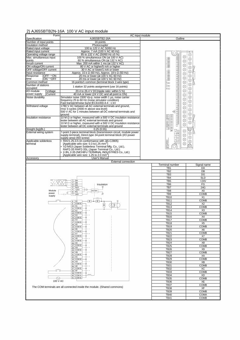
2) AJ65SBTB2N-16A 100 V AC input module Form AC input module
Specification AJ65SBTB2-16A Outline Number of input points 16 points Insulation method Photocoupler Rated input voltage 100 to 120 V AC 50/60 Hz Rated input current Approx. 7 mA (100 V AC 60 Hz) Operating voltage range 85 to 132 V AC (50/60 Hz ±5 %) Max. simultaneous input points
100 % simultaneous ON (at 100 V AC) 60 % simultaneous ON (at 132 V AC)
Inrush current Max. 200 mA within 1 ms (at 132 V AC) ON voltage/ON current 80 V AC or higher/5 mA or higher OFF voltage/OFF current 30 V AC or lower/1 mA or lower Input resistance Approx. 15 k Ω (60 Hz), Approx. 18 k Ω (50 Hz)
OFF ON 20 ms or lower (at 100 V AC 60 Hz) Response time ON OFF 20 ms or lower (at 100 V AC 60 Hz) Common method 16 points/1 common (terminal block 2-wire type) Number of stations occupied 1 station 32 points assignment (use 16 points)
Voltage 20.4 to 26.4 V DC(ripple ratio: within 5 %) I/O module power supply Current 40 mA or lower (24 V DC and all point is ON) Noise durability Simulator noise 1500 Vp-p, noise width 1 µs, noise carrier
frequency 25 to 60 Hz (noise simulator condition) Fast transient/noise burst IEC61000-4-4 : 1 kV
Withstand voltage 1780 V AC between all AC external terminals and ground, rms/ 3 cycles (2000 m above sea level) 500 V AC for 1 minutes between all DC external terminals and ground
Insulation resistance 10 M Ω or higher, measured with a 500 V DC insulation resistance tester between all AC external terminals and ground 10 M Ω or higher, measured with a 500 V DC insulation resistance tester between all DC external terminals and ground
Weight (kg)(lb.) 0.25 (0.55) External wiring system 7-point 2-piece terminal block (transmission circuit, module power
COM BX1COM BX2COM BX3COM BX4COM BX5COM BX6COM BX7COM BX8COM BX9COM BXACOM BXBCOM BXCCOM BXDCOM BXECOM BXFCOM BCOM ACOM B
1011121314
1615
17181920
2221
23242526
2827
29303132
3433
35363738
4039
41
100 V AC
Insulation
R R
R
DC/DCModulepowersupply
The COM terminals are all connected inside the module. (Shared commons)
TB41 COMB
3) AJ65SBTB3-8D 24 V DC input module (Sink/source loading) Form DC input module
Specification AJ65SBTB3-8D Outline Number of input points 16 points Insulation method Photocoupler Rated input voltage 24 V DC Rated input current Approx. 7 mA Operating voltage range 19.2 to 26.4 V DC
(ripple ratio: within 5 %) Max. simultaneous ON input points
100 %
ON voltage/ON current 14 V or higher/3.5 mA or higher OFF voltage/OFF current 6 V or lower/1.7 mA or lower Input resistance Approx. 3.3 kΩ Response OFF ON 1.5 ms or lower (when 24 V DC) time ON OFF 1.5 ms or lower (when 24 V DC) Common wiring method 8 points/1 common
(terminal block B-wire type) Input method Sink/source shared type Number of stations occupied 1 station 32 points assignment (use 8 points) I/O module Voltage 20.4 to 26.4 V DC (ripple rate: within 5 %) power supply Current 40 mA or lower (when 24 V DC and all point is ON) Noise durability DC type noise voltage 500 Vp-p, noise width 1 µs, noise carrier
frequency 25 to 60 Hz (noise simulator condition) Withstand voltage 500 V AC for 1 minute between all DC external terminals and
ground Insulation resistance 10 M Ω or higher, measured with a 500 V DC insulation resistance
tester Weight (kg) 0.18 External wiring system 7-point 2-piece terminal block (transmission circuit, module power
TB1 DA TB2 DB TB3 DG TB4 SLD TB5 +24V TB6 FG TB7 24G TB8 X0 TB9 COMA TB10 X1 TB11 COMB TB12 X2 TB13 COMA TB14 X3 TB15 COMB TB16 X4 TB17 COMA TB18 X5 TB19 COMB TB20 X6 TB21 COMA TB22 X7 TB23 COMB TB24 DC24A
Module powersupply
DC/DC
DADBDGSLD+24VFG24G
21
34567
Insulation
X0COMAX1COMBX2COMAX3
98
1011121314
COMBX4COMAX5COMBX6COMA
1615
1718192021
X7COMBDC24ADC24B
22232425
24 V DC
R
R
3-wire type sensor
2-wire typesensor
Source Sink
TB25 DC24B
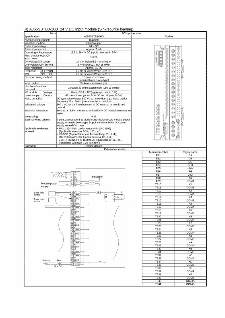
4) AJ65SBTB3-16D 24 V DC input module (Sink/source loading) Form DC input module
Specification AJ65SBTB3-16D Outline Number of input points 16 points Insulation method Photocoupler Rated input voltage 24 V DC Rated input current Approx. 7 mA Operating voltage range 19.2 to 26.4 V DC (ripple ratio: within 5 %) Max. simultaneous ON input points 100 %
ON voltage/ON current 14 V or higher/3.5 mA or higher OFF voltage/OFF current 6 V or lower/1.7 mA or lower Input resistance Approx. 3.3 kΩ
OFF ON 1.5 ms or lower (When 24 V DC) Response time ON OFF 1.5 ms or lower (When 24 V DC) Common wiring method 16 points/1 common
(terminal block 3-wire type) Input method Sink/source shared type Number of stations occupied 1 station 32 points assignment (use 16 points)
I/O module Voltage 20.4 to 26.4 V DC(ripple ratio: within 5 %) power supply Current 45 mA or lower (when 24 V DC and all point is ON) Noise durability DC type noise voltage 500 Vp-p, noise width 1 µs, noise carrier
frequency 25 to 60 Hz (noise simulator condition) Withstand voltage 500 V AC for 1 minute between all DC external terminals and
ground Insulation resistance 10 M Ω or higher, measured with a 500 V DC insulation resistance
tester Weight (kg) 0.25 External wiring system 7-point 2-piece terminal block (transmission circuit, module power
Specification AJ65SBTB2-8T Outline Number of output points 8 points Insulation method Photocoupler Rated load voltage 12/24 V DC Operating load voltage range 10.2 to 26.4 V DC (ripple ratio: within 5 %)
Max. load current 0.5 A/point (when all point 5 are ON: 0.3 A/point) 2.4 A/1 common
Max. inrush current 1.0 A 10 ms or lower Leakage current at OFF 0.25 mA or lower Voltage drop at ON 0.3 V or lower (TYP) 0.5 A
0.6 V or lower (MAX) 0.5 A Response OFF ON 0.5 ms or lower time ON OFF 1.5 ms or lower (resistive load) External Voltage 10.2 to 26.4 V DC (ripple ratio: within 5 %) Power supply for output
Current 17.8 mA or lower (TYP.24 V DC/1 common) Not including external load current
Surge suppression Zener diode Common wiring method 8 points/1 common
(terminal block 2-wire type) Number of stations occupied
1 station 32 points assignment (use 8 points)
I/O module Voltage 20.4 to 26.4 V DC (ripple ratio: within 5 %) power supply Current 45 mA or lower (when 24 V DC and all point is ON) Noise durability DC type noise voltage 500 Vp-p, noise width 1 µs, noise carrier
frequency 25 to 60 Hz (noise simulator condition) Withstand voltage 500 V AC for 1 minute between all DC external terminals and
ground Insulation resistance 10 MΩ or higher, measured with a 500 V DC insulation resistance
tester Weight (kg) 0.18 External wiring system 7-point 2-piece terminal block (transmission circuit, module power
TB1 DA TB2 DB TB3 DG TB4 SLD TB5 +24V TB6 FG TB7 24G TB8 Y0 TB9 COM TB10 Y1 TB11 COM TB12 Y2 TB13 COM TB14 Y3 TB15 COM TB16 Y4 TB17 COM TB18 Y5 TB19 COM TB20 Y6 TB21 COM TB22 Y7 TB23 COM TB24 DC24V TB25 DC24G
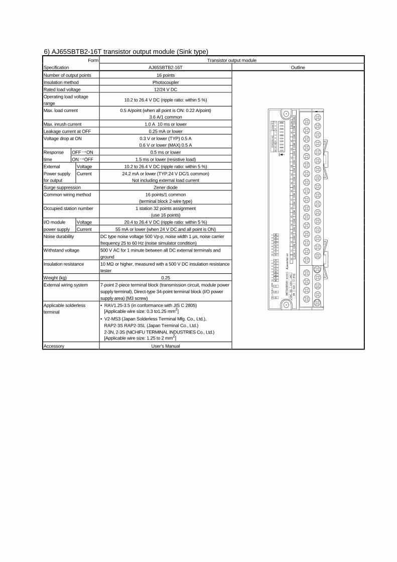
Specification AJ65SBTB2-16T Outline Number of output points 16 points Insulation method Photocoupler Rated load voltage 12/24 V DC Operating load voltage range
10.2 to 26.4 V DC (ripple ratio: within 5 %)
Max. load current 0.5 A/point (when all point is ON: 0.22 A/point) 3.6 A/1 common
Max. inrush current 1.0 A 10 ms or lower Leakage current at OFF 0.25 mA or lower Voltage drop at ON 0.3 V or lower (TYP) 0.5 A
0.6 V or lower (MAX) 0.5 A Response OFF ON 0.5 ms or lower time ON OFF 1.5 ms or lower (resistive load) External Voltage 10.2 to 26.4 V DC (ripple ratio: within 5 %) Power supply for output
Current 24.2 mA or lower (TYP.24 V DC/1 common) Not including external load current
Surge suppression Zener diode Common wiring method 16 points/1 common
(terminal block 2-wire type) Occupied station number 1 station 32 points assignment
(use 16 points) I/O module Voltage 20.4 to 26.4 V DC (ripple ratio: within 5 %) power supply Current 55 mA or lower (when 24 V DC and all point is ON) Noise durability DC type noise voltage 500 Vp-p, noise width 1 µs, noise carrier
frequency 25 to 60 Hz (noise simulator condition) Withstand voltage 500 V AC for 1 minute between all DC external terminals and
ground Insulation resistance 10 MΩ or higher, measured with a 500 V DC insulation resistance
tester Weight (kg) 0.25 External wiring system 7-point 2-piece terminal block (transmission circuit, module power
Terminal number Signal name TB1 DA TB2 DB TB3 DG TB4 SLD TB5 +24V TB6 FG TB7 24G TB8 Y0 TB9 COM TB10 Y1 TB11 COM TB12 Y2 TB13 COM TB14 Y3 TB15 COM TB16 Y4 TB17 COM TB18 Y5 TB19 COM TB20 Y6 TB21 COM TB22 Y7 TB23 COM TB24 Y8 TB25 COM TB26 Y9 TB27 COM TB28 YA TB29 COM TB30 YB TB31 COM TB32 YC TB33 COM TB34 YD TB35 COM TB36 YE TB37 COM TB38 YF TB39 COM TB40 DC24V
Module powersupply DC/DC
DADBDGSLD+24VFG24G
21
34567
Insulation
Y0COMY1COMY2COMY3
1011121314
COMY4COMY5COM
1615
171819
Y620COMY7COMY8COM
2221
232425
Y926COMYACOMYBCOM
2827
293031
YC32COMYDCOMYECOM
3433
353637
YF38COMDC24VDC24G
4039
41
89
L
Constant voltage circuit
I/O power supply (external supply power)
TB41 DC24G
7) AJ65SBTB2N-8R relay output module Form Relay output module
Specification AJ65SBTB2N-8R Outline Number of output points 8 points Insulation method Relay Rated load voltage⋅current 24 V DC (resistive load), 240 V AC (cosφ = 1)/
2 A/point 4 A/common Min. switching load 5 V DC 1 mA Max. switching voltage 264 V AC 125 V DC Response OFF ON 10 ms or lower time ON OFF 12 ms or lower
Mechanical 20 million times or more Rated switching voltage⋅current load 10 million times or more
200 V AC 1.5 A, 240 V AC 1 A (cosφ = 0.7) 10 million times or more
200 V AC 1 A, 240 V AC 0.5 A (cosφ = 0.35) 10 million times or more
Life Electrical
24 V DC 1 A, 100 V DC 0.1 A (L/R = 7 ms) 10 million times or more
Max. switching frequency 3600 times/hour Surge suppression None Common method 8 points/1 common (terminal block 2-wire type) Number of stations occupied 1 station 32 points assignment (use 8 points)
I/O module Voltage 20.4 to 26.4 V DC(ripple ratio: within 5 %) power supply Current 85 mA or lower (when 24 V DC and all point is ON) Noise durability Simulator noise 1500 Vp-p, noise width 1 µs, noise carrier
frequency 25 to 60 Hz (noise simulator condition) Fast transient/noise burst IEC61000-4-4 : 1 kV
Withstand voltage 2830 V AC between all AC external terminals and ground, rms/ 3 cycles (2000 m above sea level) 500 V AC for 1 minutes between all DC external terminals and ground
Insulation resistance 10 M Ω or higher, measured with a 500 V DC insulation resistance tester between all AC external terminals and ground 10 M Ω or higher, measured with a 500 V DC insulation resistance tester between all DC external terminals and ground
The COM terminals are all connected inside the module. (Shared commons)
8) AJ65SBTB2N-16R relay output module Form Relay output module
Specification AJ65SBTB2N-16R Outline Number of output points 16 points Insulation method Relay Rated load voltage⋅current 24 V DC (resistive load), 240 V AC (cosφ = 1)/
2 A/point 8 A/1 common Min. switching load 5 V DC 1 mA Max. switching voltage 264 V AC 125 V DC Response OFF ON 10 ms or lower time ON OFF 12 ms or lower
Mechanical 20 million times or more Rated switching voltage⋅current load 10 million times or more
200 V AC 1.5 A, 240 V AC 1 A (cosφ = 0.7) 10 million times or more 200 V AC 1 A, 240 V AC 0.5 A (cosφ = 0.35) 10 million times or more
Life Electrical
24 V DC 1 A, 240 V DC 1 A (L/R = 7 ms) 10 million times or more Max. switching frequency 3600 times/hour Surge suppression None Common method 16 points/1 common (terminal block 2-wire type) Number of stations occupied 1 station 32 points assignment (use 16 points) I/O module Voltage 20.4 to 26.4 V DC(ripple ratio: within 5 %) power supply Current 120 mA or lower (when 24 V DC and all point is ON) Noise durability Simulator noise 1500 Vp-p, noise width 1 µs, noise carrier frequency 25
to 60 Hz (noise simulator condition) Fast transient/noise burst IEC61000-4-4 : 1 kV
Withstand voltage 2830 V AC between all AC external terminals and ground, rms/ 3 cycles (2000 m above sea level) 500 V AC for 1 minutes between all DC external terminals and ground
Insulation resistance 10 M Ω or higher, measured with a 500 V DC insulation resistance tester between all AC external terminals and ground 10 M Ω or higher, measured with a 500 V DC insulation resistance tester between all DC external terminals and ground
Weight (kg) (lb.) 0.35 (0.77) External wiring system 7-point 2-piece terminal block (transmission circuit, module power
The COM terminals are all connected inside the module. (Shared commons)
TB41 COMB
9) AJ65SBTB2N-8S triac output module Form Triac output module
Specification AJ65SBTB2N-8S Outline Number of output points 8 points Insulation method Photocoupler Rated load voltage⋅ 100 to 240 V AC 50/60 Hz ± 5 % Max. load voltage 264 V AC Max. load current 0.6 A/point, 2.4 A/1 common Min. load voltage⋅current 50 V AC 100 mA, 100 V AC 10 mA, 240 V AC 10 mA Max. inrush current 25 A 10 ms or lower Leakage current at OFF 1.5 mA rms or lower (100 V AC rms 60 Hz),
3 mA rms or lower (200 V AC rms 60 Hz) Max. voltage drop at ON 1.5 V rms or lower (at 0.6 A) Response OFF ON 1 ms or lower time ON OFF 1/2 cycle + 1 ms or lower Surge suppression C·R absorver (0.01 µF + 47 Ω) Common method 8 points/1 common (terminal block 2-wire type) Number of stations occupied 1 station 32 points assignment (use 8 points)
I/O module Voltage 20.4 to 26.4 V DC(ripple ratio: within 5 %) power supply Current 55 mA or lower (when 24 V DC and all point is ON) Noise durability Simulator noise 1500 Vp-p, noise width 1 µs, noise carrier
frequency 25 to 60 Hz (noise simulator condition) Fast transient/noise burst IEC61000-4-4 : 1 kV
Withstand voltage 2830 V AC between all AC external terminals and ground, rms/ 3 cycles (2000 m above sea level) 500 V AC for 1 minutes between all DC external terminals and ground
Insulation resistance 10 M Ω or higher, measured with a 500 V DC insulation resistance tester between all AC external terminals and ground 10 M Ω or higher, measured with a 500 V DC insulation resistance tester between all DC external terminals and ground
The COM terminals are all connected inside the module. (Shared commons)
10) AJ65SBTB2N-16S triac output module Form Triac output module
Specification AJ65SBTB2N-16S Outline Number of output points 16 points Insulation method Photocoupler Rated load voltage 100 to 240 V AC 50/60 Hz ± 5 % Max. load voltage 264 V AC Max. load current 0.6 A/point, 4.8A/1 common Min. load voltage⋅current 50 V AC 100 mA, 100 V AC 10 mA, 240 V AC 10 mA Max. inrush current 25 A 10 ms or lower Leakage current at OFF 1.5 mA rms or lower (100 V AC rms 60 Hz),
3 mA rms or lower (200 V AC rms 60 Hz) Max. voltage drop at ON 1.5 V rms or lower (at 0.6 A) Response OFF ON 1 ms or lower time ON OFF 1/2 cycle + 1 ms or lower Surge suppression C·R absorver (0.01 µF + 47 Ω) Common method 16 points/1 common (terminal block 2-wire type) Number of stations occupied 1 station 32 points assignment (use 16 points) I/O module Voltage 20.4 to 26.4 V DC(ripple ratio: within 5 %) power supply Current 85 mA or lower (when 24 V DC and all point is ON) Noise durability Simulator noise 1500 Vp-p, noise width 1 µs, noise carrier
frequency 25 to 60 Hz (noise simulator condition) Fast transient/noise burst IEC61000-4-4 : 1 kV
Withstand voltage 2830 V AC between all AC external terminals and ground, rms/ 3 cycles (2000 m above sea level) 500 V AC for 1 minutes between all DC external terminals and ground
Insulation resistance 10 M Ω or higher, measured with a 500 V DC insulation resistance tester between all AC external terminals and ground 10 M Ω or higher, measured with a 500 V DC insulation resistance tester between all DC external terminals and ground
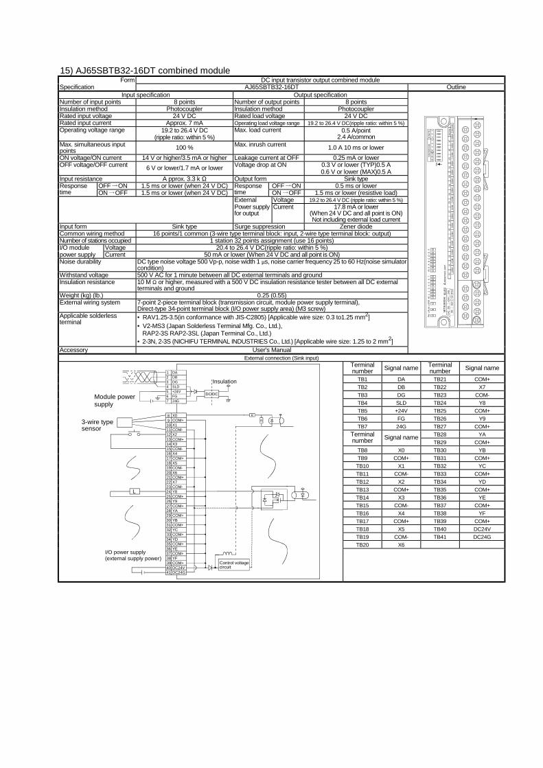
Number of input points 8 points Number of output points 16 points Insulation method Photocoupler Insulation method Photocoupler Rated input voltage 24 V DC Rated load voltage 24 V DC Rated input current Approx. 7 mA Operating load voltage range 19.2 to 26.4 V DC(ripple ratio: within 5 %) Operating voltage range 19.2 to 26.4 V DC
(ripple ratio: within 5 %) Max. load current 0.5 A/point
(when all point 5 are ON : 0.225 A/1 point) 3.6 A/common
Max. simultaneous input points 100 % Max. inrush current 1.0 A 10 ms or lower ON voltage/ON current 14 V or higher/3.5 mA or higher Leakage current at OFF 0.25 mA or lower
0.3 V or lower (TYP)0.5 A OFF voltage/OFF current 6 V or lower/1.7 mA or lower Voltage drop at ON 0.6 V or lower (MAX)0.5 A
Input resistance A pprox. 3.3 k Ω
Output form Sink type with overload protection frunction, overvoltage protection function, overheat protection function.
OFF ON 1.5 ms or lower (when 24 V DC) OFF ON 0.5 ms or lower Response time ON OFF 1.5 ms or lower (when 24 V DC)
Response time ON OFF 1.5 ms or lower (resistive load) External Voltage 19.2 to 26.4 V DC (ripple ratio: within 5 %) Power supply for output
Current 110 mA or lower (Per 24 V DC/1 common)
Not including external load current Input form Sink type Surge suppression Zener diode Common wiring method 16 points/1 common (Terminal block single wire type) Number of stations occupied 1 station 32 points assignment (use 16 points) I/O module Voltage 20.4 to 26.4 V DC(ripple ratio: within 5 %) power supply Current 50 mA or lower (when 24 V DC and all point is ON) Noise durability DC type noise voltage 500 Vp-p, noise width 1 µs, noise carrier frequency 25 to 60 Hz(noise simulator
condition) Withstand voltage 500 V AC for 1 minute between all DC external terminals and ground Insulation resistance 10 M Ω or higher, measured with a 500 V DC insulation resistance tester between all DC external
terminals and ground Weight (kg) (lb.) 0.18 (0.4) External wiring system 7-point 2-piece terminal block (transmission circuit, module power supply terminal),
Number of input points 8 points Number of output points 8 points Insulation method Photocoupler Insulation method Photocoupler Rated input voltage 24 V DC Rated load voltage 24 V DC Rated input current Approx. 5 mA Operating load voltage range 19.2 to 26.4 V DC(ripple ratio: within 5 %) Operating voltage range 19.2 to 26.4 V DC
(ripple ratio: within 5 %) Max. load current 0.5 A/point
2.4 A/common Max. simultaneous input points 100 % Max. inrush current 1.0 A 10 ms or lower ON voltage/ON current 15 V or higher/3.0 mA or higher Leakage current at OFF 0.25 mA or lower
0.3 V or lower (TYP)0.5 A OFF voltage/OFF current 3 V or lower/0.5 mA or lower Voltage drop at ON 0.6 V or lower (MAX)0.5 A
Input resistance A pprox. 4.7 k Ω Output form Sink type OFF ON 0.2 ms or lower (when 24 V DC) OFF ON 0.5 ms or lower Response
time ON OFF 0.2 ms or lower (when 24 V DC) Sink type
ON OFF 1.5 ms or lower (resistive load) External Voltage 19.2 to 26.4 V DC (ripple ratio: within 5 %) Power supply for output
Current 17.8 mA or lower (When 24 V DC and all point is ON) Not including external load current
Input form Sink type Surge suppression Zener diode Common wiring method 16 points/1 common (Terminal block single wire type) Number of stations occupied 1 station 32 points assignment (use 16 points) I/O module Voltage 20.4 to 26.4 V DC(ripple ratio: within 5 %) power supply Current 55 mA or lower (When 24 V DC and all point is ON) Noise durability DC type noise voltage 500 Vp-p, noise width 1 µs, noise carrier frequency 25 to 60 Hz(noise simulator
condition) Withstand voltage 500 V AC for 1 minute between all DC external terminals and ground Insulation resistance 10 M Ω or higher, measured with a 500 V DC insulation resistance tester between all DC external
terminals and ground Weight (kg) (lb.) 0.18 (0.4) External wiring system 7-point 2-piece terminal block (transmission circuit, module power supply terminal),
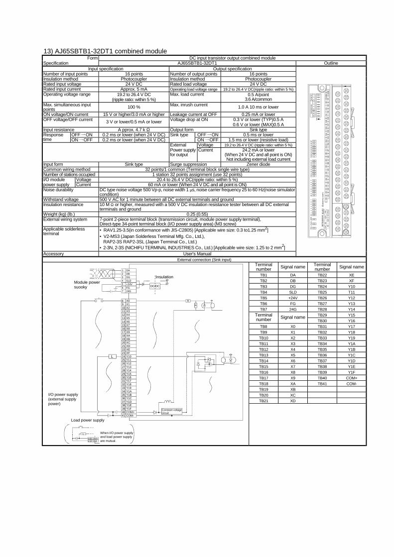
Number of input points 16 points Number of output points 16 points Insulation method Photocoupler Insulation method Photocoupler Rated input voltage 24 V DC Rated load voltage 24 V DC Rated input current Approx. 5 mA Operating load voltage range 19.2 to 26.4 V DC(ripple ratio: within 5 %) Operating voltage range 19.2 to 26.4 V DC
(ripple ratio: within 5 %) Max. load current 0.5 A/point
3.6 A/common Max. simultaneous input points 100 % Max. inrush current 1.0 A 10 ms or lower ON voltage/ON current 15 V or higher/3.0 mA or higher Leakage current at OFF 0.25 mA or lower
0.3 V or lower (TYP)0.5 A OFF voltage/OFF current 3 V or lower/0.5 mA or lower Voltage drop at ON 0.6 V or lower (MAX)0.5 A
Input resistance A pprox. 4.7 k Ω Output form Sink type OFF ON 0.2 ms or lower (when 24 V DC) OFF ON 0.5 ms or lower Response
time ON OFF 0.2 ms or lower (when 24 V DC) Sink type
ON OFF 1.5 ms or lower (resistive load) External Voltage 19.2 to 26.4 V DC (ripple ratio: within 5 %) Power supply for output
Current 24.2 mA or lower (When 24 V DC and all point is ON) Not including external load current
Input form Sink type Surge suppression Zener diode Common wiring method 32 points/1 common (Terminal block single wire type) Number of stations occupied 1 station 32 points assignment (use 32 points) I/O module Voltage 20.4 to 26.4 V DC(ripple ratio: within 5 %) power supply Current 60 mA or lower (When 24 V DC and all point is ON) Noise durability DC type noise voltage 500 Vp-p, noise width 1 µs, noise carrier frequency 25 to 60 Hz(noise simulator
condition) Withstand voltage 500 V AC for 1 minute between all DC external terminals and ground Insulation resistance 10 M Ω or higher, measured with a 500 V DC insulation resistance tester between all DC external
terminals and ground Weight (kg) (lb.) 0.25 (0.55) External wiring system 7-point 2-piece terminal block (transmission circuit, module power supply terminal),
Number of input points 4 points Number of output points 4 points Insulation method Photocoupler Insulation method Photocoupler Rated input voltage 24 V DC Rated load voltage 24 V DC Rated input current Approx. 7 mA Operating load voltage range 19.2 to 26.4 V DC(ripple ratio: within 5 %) Operating voltage range 19.2 to 26.4 V DC
(ripple ratio: within 5 %) Max. load current 0.5 A/point
1.2 A/common Max. simultaneous input points 100 % Max. inrush current 1.0 A 10 ms or lower ON voltage/ON current 14 V or higher/3.5 mA or higher Leakage current at OFF 0.25 mA or lower
0.3 V or lower (TYP)0.5 A OFF voltage/OFF current 6 V or lower/1.7 mA or lower Voltage drop at ON 0.6 V or lower (MAX)0.5 A
Input resistance A pprox. 3.3 k Ω Output form Sink type OFF ON 1.5 ms or lower (when 24 V DC) OFF ON 0.5 ms or lower Response
time ON OFF 1.5 ms or lower (when 24 V DC) Response time ON OFF 1.5 ms or lower (resistive load) External Voltage 19.2 to 26.4 V DC (ripple ratio: within 5 %) Power supply for output
Current 14.6 mA or lower (When 24 V DC and all point is ON) Not including external load current
Input form Sink type Surge suppression Zener diode Common wiring method 8 points/1 common (3-wire type terminal block: input, 2-wire type terminal block: output) Number of stations occupied 1 station 32 points assignment (use 8 points) I/O module Voltage 20.4 to 26.4 V DC(ripple ratio: within 5 %) power supply Current 45 mA or lower (When 24 V DC and all point is ON) Noise durability DC type noise voltage 500 Vp-p, noise width 1 µs, noise carrier frequency 25 to 60 Hz(noise simulator
condition) Withstand voltage 500 V AC for 1 minute between all DC external terminals and ground Insulation resistance 10 M Ω or higher, measured with a 500 V DC insulation resistance tester Weight (kg) (lb.) 0.18 (0.4) External wiring system 7-point 2-piece terminal block (transmission circuit, module power supply terminal),
Number of input points 8 points Number of output points 8 points Insulation method Photocoupler Insulation method Photocoupler Rated input voltage 24 V DC Rated load voltage 24 V DC Rated input current Approx. 7 mA Operating load voltage range 19.2 to 26.4 V DC(ripple ratio: within 5 %) Operating voltage range 19.2 to 26.4 V DC
(ripple ratio: within 5 %) Max. load current 0.5 A/point
2.4 A/common Max. simultaneous input points 100 % Max. inrush current 1.0 A 10 ms or lower ON voltage/ON current 14 V or higher/3.5 mA or higher Leakage current at OFF 0.25 mA or lower
0.3 V or lower (TYP)0.5 A OFF voltage/OFF current 6 V or lower/1.7 mA or lower Voltage drop at ON 0.6 V or lower (MAX)0.5 A
Input resistance A pprox. 3.3 k Ω Output form Sink type OFF ON 1.5 ms or lower (when 24 V DC) OFF ON 0.5 ms or lower Response
time ON OFF 1.5 ms or lower (when 24 V DC) Response time ON OFF 1.5 ms or lower (resistive load) External Voltage 19.2 to 26.4 V DC (ripple ratio: within 5 %) Power supply for output
Current 17.8 mA or lower (When 24 V DC and all point is ON) Not including external load current
Input form Sink type Surge suppression Zener diode Common wiring method 16 points/1 common (3-wire type terminal block: input, 2-wire type terminal block: output) Number of stations occupied 1 station 32 points assignment (use 16 points) I/O module Voltage 20.4 to 26.4 V DC(ripple ratio: within 5 %) power supply Current 50 mA or lower (When 24 V DC and all point is ON) Noise durability DC type noise voltage 500 Vp-p, noise width 1 µs, noise carrier frequency 25 to 60 Hz(noise simulator
condition) Withstand voltage 500 V AC for 1 minute between all DC external terminals and ground Insulation resistance 10 M Ω or higher, measured with a 500 V DC insulation resistance tester between all DC external
terminals and ground Weight (kg) (lb.) 0.25 (0.55) External wiring system 7-point 2-piece terminal block (transmission circuit, module power supply terminal),
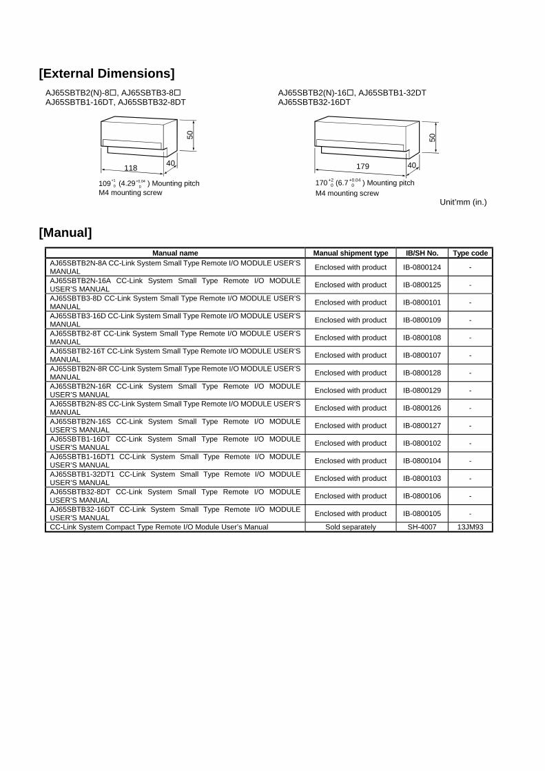
Manual name Manual shipment type IB/SH No. Type code AJ65SBTB2N-8A CC-Link System Small Type Remote I/O MODULE USER’S MANUAL Enclosed with product IB-0800124 -
AJ65SBTB2N-16A CC-Link System Small Type Remote I/O MODULE USER’S MANUAL Enclosed with product IB-0800125 -
AJ65SBTB3-8D CC-Link System Small Type Remote I/O MODULE USER’S MANUAL Enclosed with product IB-0800101 -
AJ65SBTB3-16D CC-Link System Small Type Remote I/O MODULE USER’S MANUAL Enclosed with product IB-0800109 -
AJ65SBTB2-8T CC-Link System Small Type Remote I/O MODULE USER’S MANUAL Enclosed with product IB-0800108 -
AJ65SBTB2-16T CC-Link System Small Type Remote I/O MODULE USER’S MANUAL Enclosed with product IB-0800107 -
AJ65SBTB2N-8R CC-Link System Small Type Remote I/O MODULE USER’S MANUAL Enclosed with product IB-0800128 -
AJ65SBTB2N-16R CC-Link System Small Type Remote I/O MODULE USER’S MANUAL Enclosed with product IB-0800129 -
AJ65SBTB2N-8S CC-Link System Small Type Remote I/O MODULE USER’S MANUAL Enclosed with product IB-0800126 -
AJ65SBTB2N-16S CC-Link System Small Type Remote I/O MODULE USER’S MANUAL Enclosed with product IB-0800127 -
AJ65SBTB1-16DT CC-Link System Small Type Remote I/O MODULE USER’S MANUAL Enclosed with product IB-0800102 -
AJ65SBTB1-16DT1 CC-Link System Small Type Remote I/O MODULE USER’S MANUAL Enclosed with product IB-0800104 -
AJ65SBTB1-32DT1 CC-Link System Small Type Remote I/O MODULE USER’S MANUAL Enclosed with product IB-0800103 -
AJ65SBTB32-8DT CC-Link System Small Type Remote I/O MODULE USER’S MANUAL Enclosed with product IB-0800106 -
AJ65SBTB32-16DT CC-Link System Small Type Remote I/O MODULE USER’S MANUAL Enclosed with product IB-0800105 -
CC-Link System Compact Type Remote I/O Module User’s Manual Sold separately SH-4007 13JM93
00 (MEE) Specifications subject to change without notice. Printed in Japan on recycled paper.
Country/Region Sales office Tel/Fax U.S.A Mitsubishi Electric Automation Inc.
500 Corporate Woods Parkway Vernon Hills, IL 60061 Tel : 1-847-478-2100 Fax : 1-847-478-0328
Brazil MELCO-TEC Rep. Com.e Assessoria Tecnica Ltda. Av. Rio Branco, 123-15 ,and S/1507, Rio de Janeiro, RJ CEP 20040-005, Brazil
Tel : 55-21-221-8343 Fax : 55-21-221-9388
Germany Mitsubishi Electric Europe B.V. German Branch Gothaer Strasse 8 D-40880 Ratingen, GERMANY
Tel : 49-2102-486-0 Fax : 49-2102-486-717
U.K Mitsubishi Electric Europe B.V. UK Branch Travellers Lane, Hatfield, Herts., AL10 8XB,UK
Tel : 44-1707-276100 Fax : 44-1707-278695
Italy Mitsubishi Electric Europe B.V. Italian Branch Centro Dir. Colleoni, Pal. Perseo - Ingr.2 Via Paracelso 12, 20041 Agrate B., Milano, Italy
Tel : 39-039-6053301 Fax : 39-039-6053206
Spain Mitsubishi Electric Europe B.V. Spanish Branch Pol. Ind. "Can Magi"- C/.Joan Buscalla, 2-4-A.C.420 08190 Sant Cugat del Valles, Barcelona, Spain
Tel : 34-935-653135 Fax : 34-935-891579
South Africa MSA Manufacturing (Pty) Ltd. P O Box 39733 Bramley 201 8 Johannesburg, South Africa
Tel : 27-11-444-8080 Fax : 27-11-444-8304
Hong Kong Ryoden International Ltd. 10th Floor, Manulife Tower, 169 Electric Road, North Point, HongKong
Tel : 852-2887-8870 Fax : 852-2887-7984
China Ryoden International Shanghai Ltd. 3F Block5 Building Automation Instrumentation Plaza 103 Cao Bao Rd. Shanghai 200233 China
Korea STC Techno Seoul Co., Ltd. 1F Dong Seo Game Channel Bldg., 660-11,Deungchon-dong Kangsec-ku, Seoul, Korea
Tel : 82-2-3668-6567 Fax : 82-2-3664-8335
Singapore Mitsubishi Electric Asia Pte, Ltd. 307 ALEXANDRA ROAD #05-01/02, MITSUBISHI ELECTRIC BUILDING SINGAPORE 159943
Tel : 65-473-2480 Fax : 65-476-7439
Thailand F. A. Tech Co.,Ltd. 1138/33-34 Rama 3 Road, Yannawa, Bangkok 10120, Thailand
Tel : 66-2-295-2861 Fax : 66-2-295-2865
Indonesia P.T. Autoteknindo SUMBER MAKMUR Kompleks Agung Sedayu Propertindo (Harco Mangga Dua) Blok H No.4 JI Mangga Dua Raya Jakarta Pusat 10730-Indonesia.
Tel : 62-21-336292 Fax : 62-21-330378
India Messung Systems Put,Ltd. Electronic Sadan NO:111 Unit No15, M.I.D.C BHOSARI,PUNE-411026
Tel : 91-20-7128927 Fax : 91-20-7128108
Australia Mitsubishi Electric Australia Pty. Ltd. 348 Victoria Road, PostalBag, No 2, Rydalmere, N.S.W 2116, Australia
Tel : 61-2-9684-7777 Fax : 61-2-9684-7245
HEAD OFFICE:MITSUBISHI DENKI BLDG MARUNOUCHI TOKYO 100-8310 TELEX:J24532 CABLE MELCO TOKYO


![051224 - Nipron · 051224 - 6 - Model ePCSA-500P-X2S Item Efficiency at AC Input at AC Input Input Efficiency [%] Voltage [V] 50% Load 100% Load 85V AC 71.83 71.35](https://static.documents.pub/doc/80x56/6040066dbeaefa3a96117276/051224-051224-6-model-epcsa-500p-x2s-item-efficiency-at-ac-input-at-ac-input.jpg)


![Proxima Centaur™ EF Control Unit - Caldertech...Input Frequency 40 - 60Hz Input Current [Max. A] 16A Input Power 3kW Output Voltage [Vac RMS] 8 - 48v Output Current [Continuous.](https://static.documents.pub/doc/80x56/6132fe13dfd10f4dd73acd61/proxima-centaura-ef-control-unit-caldertech-input-frequency-40-60hz-input.jpg)


![060201 - Nipron · 060201 Model eNSP4-500P-SA0-H1V Item Power Factor at AC Input at AC Input Input Power Factor [%] Voltage [V] 50%Load 100% Load 85V AC 98. 45 99. 91](https://static.documents.pub/doc/80x56/6040066abeaefa3a96117264/060201-060201-model-ensp4-500p-sa0-h1v-item-power-factor-at-ac-input-at-ac-input.jpg)


