Deliverable FP7-ICT 608637/D1.2 Date :August 2014 Public Deliverable MiWEBA D1.2: Specification of architecture Page 1 MiWEBA Millimeter-Wave Evolution for Backhaul and Access EU Contract No. FP7-ICT-608637 WP1: Scenarios and Use Cases, Architectures and Business Models D1.2: Specification of architecture Contractual date: M14 Actual date: August 2014 Authors: See list Work package: D1.2 Specification of architecture Security: Public Nature: Report Version: 1.5 Number of pages: 40 Abstract This report describes specification of architecture referred by the MiWEBA project dealing with mm-wave overlay heterogeneous network (HetNet), which defines the modules and functions of the architecture necessary to enable the separation of the control plane and user plane in the new system proposed by this project and a flexible management of the overlay of millimeter-waves cells. Keywords Multi-RAT, Multi-Techno HetNets, Control plane and user plain separation, mm-wave overlay, relay nodes, All rights reserved. The document is proprietary of the MiWEBA consortium members. No copy or distribution, in any form or by any means, is allowed without the prior written agreement of the owner of the property rights.
Transcript
Deliverable FP7-ICT 608637/D1.2
Date :August 2014 Public Deliverable
MiWEBA D1.2: Specification of architecture Page 1
MiWEBA Millimeter-Wave Evolution for Backhaul and Access
EU Contract No. FP7-ICT-608637
WP1: Scenarios and Use Cases, Architectures and Business Models D1.2: Specification of architecture
Contractual date: M14
Actual date: August 2014
Authors: See list
Work package: D1.2 Specification of architecture
Security: Public
Nature: Report
Version: 1.5
Number of pages: 40
Abstract
This report describes specification of architecture referred by the MiWEBA project dealing with mm-wave overlay heterogeneous network (HetNet), which defines the modules and functions of the architecture necessary to enable the separation of the control plane and user plane in the new system proposed by this project and a flexible management of the overlay of millimeter-waves cells.
Keywords
Multi-RAT, Multi-Techno HetNets, Control plane and user plain separation, mm-wave overlay, relay nodes,
All rights reserved.
The document is proprietary of the MiWEBA consortium members. No copy or distribution, in any form or by any means, is allowed without the prior written agreement of the owner of the property rights.
2
MiWEBA D1.2: Specification of architecture Page 2
This document reflects only the authors’ view. The European Community is not liable for any use hat may be made of the information contained herein.
E-UTRAN Evolved Universal Terrestrial Radio Access Network
FST Fast Session Transfer
GPON Gigabit Passive Optical Network
HeNB Home eNB
HetNet Heterogeneous Network
IMT- Advanced International Mobile Telecommunications-Advanced
ITU International Telecommunication Union
LA Location Area
6
MiWEBA D1.2: Specification of architecture Page 6
LTE Long Term Evolution
LTE-A LTE-Advanced
MeNB Master eNB
MIM Multiple Interface Management
mm-wave millimeter-wave
MMR Mobile Multi-hop Relay stations
MT Multi-Techno
MTCN Multi-Technology Cellular Networks
MTLA Multi-Technology Link Adaptation
NM Network Manager
OAM Operations, Administration and Maintenance
PCI Physical Cell ID
PDCP Packet Data Convergence Protocol
QoE Quality of Experience
QoS Quality of Service
RAT Radio Access Technology
RE Radio Equipment
REC Radio Equipment Control
RIM RAN Information Management
RNs Relay Nodes
RNC Radio Network Control
RRH Remote Radio Head
RRU Remote Radio Unit
RRM Radio Resource Management
RRC Radio Resource Control
RLC Radio Link Control
SE Spectral Efficiency
SeNB Secondary eNB
SOTA State of the Arts
SRC Single Radio Controller
TA Tracking Area
TR Time Reversal
UE user terminal (user equipment)
7
MiWEBA D1.2: Specification of architecture Page 7
u-plane user plane
VNF Virtual Network Function
WWRF Wireless World Research Forum
Deliverable FP7-ICT 608637/D1.2
Date :May 2014 Public
MiWEBA D1.2: Specification of architecture Page 9
Executive Summary This public report defines the specification of architecture for the MiWEBA project that will be the reference specification for the other work packages. The most fundamental structure in the MiWEBA project is mm-wave component integration into cellular network to fulfill 1000 time network capacity increase in the next 10 years whilst keeping infrastructure costs. To realize the structure, one of the most important techniques is C/U-plane separation techniques (i.e., control plane should be used by macro cell for an efficient cell discovery and a seamless handover and user plane should be used by small cell for improving system rate). C/U plane separation will be combined with Multiple Interface Management combining Wi-Fi components operating in the 2.4/5GHz and 60 GHz bands) and LTE-A elements.
For that purpose, we first investigate the deployment of wireless networks compliant with 3GPP LTE and the cellular network paradigm proposed in the Beyond Cellular Green Generation (BCG2) project within the Green Touch Consortium as the state of the art architecture. Then we propose the specific architecture for the MiWEBA project based on them. In a second step, these architectures will be adapted to Multiple Interface Management and MT-HetNets architectures where the selection of interfaces in a given topology will be carried out using innovative MTLA techniques considering green metrics oriented on Energy Efficiency. Cellular network densification using phantom cells operating in Wi-Fi bands will be optimized thanks to MTLA metric integration in radio engineering tools.
For backhauling and fronthauling architectures, we identify the functions and modules and describe the overall architecture.
Architectural solutions approaching the C/U-plane split concept have been already considered in standard activities, like in 3GPP dual connectivity approach. In the MiWEBA project, we consider different possible split options based on Multi-Technology HetNets, the final architecture could include several of these options, which can be implemented in different scenarios to increase the capacity and limit transmission power levels and deployment costs.
Deliverable FP7-ICT 608637/D1.2
Date :August 2014 Public
MiWEBA D1.2: Specification of architecture Page 10
1 Introduction This document presents the specification of architectures based on MiWEBA scenarios and use cases investigated in Task1.1. It will be the reference specification for the other work packages. MiWEBA scenarios and use cases are described in deliverable D1.1 [1]. Scenarios are split into access and backhaul/fronthaul scenarios with three access sub scenarios (indoor, outdoor, Multi-Technology Het Net scenarios) and two backhaul/front-haul sub-scenarios covering P2P and PMP architectures and Mobile Multi-hop Relay Node schemes. Use cases are derived from these scenarios and provide a practical description of deployment scenarios detailing environments and applications. Six non exhaustive use cases (Dense Hotspot in a Shopping Mall, Dense hotspot in an Enterprise, Dense hotspot in Home and indoor, Dense hotspot in a Square, Mobility in the city and Wireless and wired backhaul) have been determined to illustrate Multi-Technology HetNet applications. D1.1 describes the general system architecture that is based on the functional separation of control and user planes at the radio interface and Multiple Interface Management combined with an optimized Multi-Technology architecture deployment.
In this document, more specific architectures which identify functions and modules in addition to overall architectures are described in relation to especially multi-RAT/MT architectures and Backhauling and front-hauling architectures. Moreover, analysis of possible splits of system components in modules and functions and the evaluation of pros and cons of different possible approaches are described. The critical issues arising from the separation of the control plane and user plane in terms of constraints on response time and computation load are also noticed.
These results lead to the definition of the modules and functions of the architecture necessary to enable the separation of the Control plane and user plane in the new system proposed by this project and a flexible management of the overlay of millimeter-waves cells.
1.1 Structure of the document In section 2 we give an overview of SOTA architectures for access and backhaul. In section 3, we describe the definitions for other work packages and MiWEBA specific architecture. In section 4, the focus is on backhauling and fronthauling with identification of the functions and modules and description of the overall the architecture. In Section 5, we consider different possible split options and evaluate constraints and foreseen gains of them.
Deliverable FP7-ICT 608637/D1.2
Date :August 2014 Public
MiWEBA D1.2: Specification of architecture Page 11
2 Overview of SOTA architectures for access and backhaul
2.1 3GPP LTE architectures The deployment of wireless networks compliant with 3GPP LTE is now progressing worldwide, with providers already offering 4G mobile services and in the next decade 5G architectures (Release 13).
Figure 2-1: 3GPP meeting plan and scheduled 3GPP releases
These systems are based on the first releases of LTE, 3GPP Rel-8/Rel-9, which were finalized in December 2008 and 2009, and represent a smooth evolution from previous 3GPP systems [2]. Compared to the 3G systems, the first release of LTE exploits OFDMA in downlink and Single Carrier-Frequency Division Multiplexing Access in the uplink; it has also introduced larger system bandwidth (up to 20 MHz) and higher order of MIMO schemes. LTE Rel-9, amongst other features, supports self-organizing network functionalities and enhanced Beamforming (BF). These features result in a more flexible usage of frequency resources, improved Spectral Efficiency (SE), higher data rate, and reduced latency.
However, 3GPP LTE standardization is continuously evolving to meet the requisites of future wireless systems. LTE Rel-10 was completed in June 2011 and it further extends the performance of LTE to fulfil the requirements for IMT-Advanced technologies as defined by the ITU [3]. This release is indicated as the initial phase of LTE-Advanced (LTE-A) process and offers relaying functionalities, up to 100 MHz of transmission bandwidth (through carrier aggregation), and enhanced inter-cell interference coordination (eICIC) mechanisms for improved support of heterogeneous deployment. Rel-11, which was frozen in March 2013, refines some of the features introduced in LTE-A, introduces enhancements in the coordinated multipoint (CoMP) transmission/reception schemes and energy saving mechanisms for the radio access network. Rel-12 is currently under study and initiates the phase indicated as beyond LTE-Advanced, which plans to boost the capacity of LTE-A and to introduce completely new wireless services. Key technologies developed in this framework are: machine- type-communication, 3D BF LTE-WiFi integration, and non-backward compatible carrier type.
In the following, we aim to present the overall architecture of LTE radio access network, named as E-UTRAN (see Figure 2-2) [4]. In LTE, the base station and the user equipment are indicated as evolved Node-B (eNB) and UE, respectively. A HetNet deployment may include low-power nodes such as picocells, femtocells (HeNBs), and Relay Nodes (RNs). An eNB serving a RN is also indicated as a Donor eNB (DeNB); however, this entity can be seen simultaneously as a DeNB from a RN and as a classic serving eNB from a UE. Moreover, a RN is classified as in-band relay, when its radio
MiWEBA D1.2: Specification of architecture Page 12
backhaul link with the DeNB uses the same frequency band as the access link; on the contrary, out-of-band relays use a dedicated band for the backhaul link.
HeNBs are typically deployed by end users to improve radio coverage in indoor environments. Furthermore, the consumer Internet connection (xDSL, cable, . . .) is used to connect them to the core network of a cellular operator. Three different approaches have been investigated in the past to manage the access at HeNBs: Closed Access, Open Access, and Hybrid Access. In Closed Access, only a restricted set of users is allowed to connect to the femtocell; in Open Access femtocells, a subscriber is always allowed to connect to the closer HeNB; in the Hybrid Access approach, femtocells allow the access to all users but a certain group of subscribers maintain higher access priority.
Figure 2-2: LTE Rel-11 radio access network architecture [4]
The S1 interface connects the eNBs to the core network: the Mobility Management Entity (MME) and the Serving Gateway (S-GW) serve as local anchors for the control and data plane, respectively. On the contrary, the X2 interface is used to directly inter-connect neighbouring eNBs for enabling functionalities like mobility management, interference mitigation, energy saving procedures, and coordinated transmissions. S1 and X2 interfaces can carry both data and signaling information. Concerning the relay architecture, the DeNB provides S1 and X2 proxy functionality between the RN and other network nodes (eNBs, MMEs, and S-GWs). Furthermore, the uN interface allows half-duplex operation for the RN. With regard to the HeNB, the LTE architecture may deploy a HeNB Gateway (HeNB GW) that provides locally the control capabilities necessary to manage large clusters of femtocells. Finally, only if the HeNB supports the Local IP Access function, which enables to connect UEs to other IP devices (like printers) via the local HeNB, the latter requires an S5 interface towards the S-GW. 3GPP multi-RAT architectures start to take shape over new study items that are outlined in the section 2.3.
2.2 Beyond Cellular Green Generation (BCG2) architecture The cellular network paradigm proposed in the Beyond Cellular Green Generation (BCG2) project within the Green Touch [6] Consortium consists of a network
Deliverable FP7-ICT 608637/D1.2
Date :August 2014 Public
MiWEBA D1.2: Specification of architecture Page 13
architecture that supports an energy-efficient network adaptation to the traffic load while guaranteeing the “always connected” constraint. The rationale behind the approach stems from the consideration that not much information needs to be exchanged in order to provide coverage: one has only to provide signaling information to allow the mobile to be paged and to reach the network when it is desired. Consequently, an architecture with better performance in term of energy consumption is an architecture where signaling and data networks are separated.
The separation brings two immediate advantages. First, base stations for data communication can be switched off as soon as no user is active under their coverage. Second, signaling base stations, which are only in charge of providing the “always connected” signaling service, can be simplified, they can be designed for low-data rates and long-range transmissions. That is clearly more efficient than the current mixing between data and signaling transmissions.
At the areas where no user is currently active, no signal from any data base station is provided in order to avoid the waste of radio resources. As soon as a user becomes active, he can communicate to the signaling base station his request and the system can provide data connectivity by turning on a data base station that can serve the user.
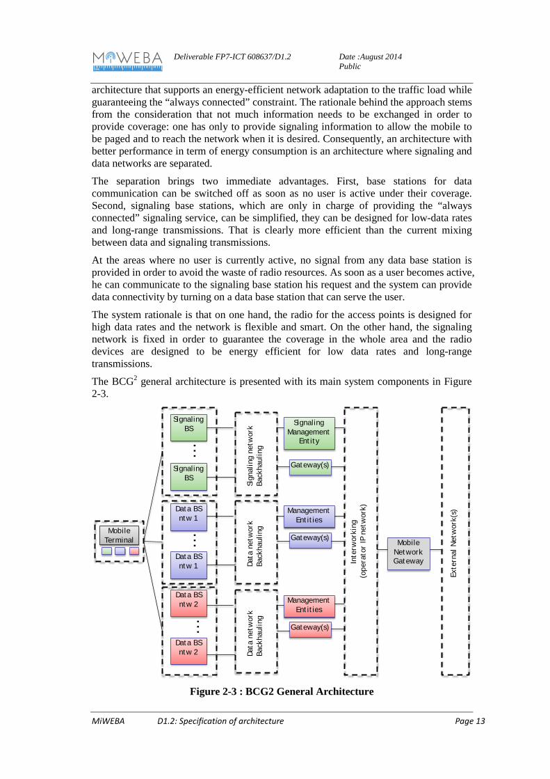
The system rationale is that on one hand, the radio for the access points is designed for high data rates and the network is flexible and smart. On the other hand, the signaling network is fixed in order to guarantee the coverage in the whole area and the radio devices are designed to be energy efficient for low data rates and long-range transmissions.
The BCG2 general architecture is presented with its main system components in Figure 2-3.
Figure 2-3 : BCG2 General Architecture
Data BS ntw 1
Sign
alin
g ne
twor
kBa
ckha
ulin
g
Data BS ntw 2
…
SignalingBS
Data BS ntw 1
Data BS ntw 2
…
SignalingBS
…
Signaling Management
Entity
Gateway(s)
Data
net
wor
kBa
ckha
ulin
g
ManagementEntities
Gateway(s)
Data
net
wor
kBa
ckha
ulin
g
ManagementEntities
Gateway(s)
Inte
rwor
king
(o
pera
tor
IP n
etw
ork)
Exte
rnal
Net
wor
k(s)
MobileTerminal Mobile
NetworkGateway
Deliverable FP7-ICT 608637/D1.2
Date :August 2014 Public
MiWEBA D1.2: Specification of architecture Page 14
The main system components are:
• Signaling Network: the Signaling Network is in charge of providing full connectivity to users and to activate data communication resources on demand.
• Data Networks: Data Networks are in charge of providing radio resources for data sessions of mobile users. Multiple and heterogeneous data networks can be adopted in BCG2. Also legacy technologies can be adapted to BCG2 operation.
• Backhaul and Internetworking: Backhaul networks are essential to interconnect data and signaling networks to the backbone network of mobile operators. Interworking between the elements of signaling network and data networks is fundamental for orchestrating overall system operation.
• Signaling Management Entity: the Signaling Management Entity is the core the whole architecture. It dialogues with UEs and data base stations to control resource activation/deactivation according to the network and user status in order to provide the best trade-off between energy consumption and user performance. It is the entity running user allocation and resource allocation algorithms, mobility issues are considered at this entity as well.
• Management Entities: Management entities control the activity of data base stations. They communicate with UEs to establish and maintain data sessions, and with the Signaling Management Entity in order to implement its directives.
2.3 3GPP and 5G Multi-RAT/MT architectures Within the framework of 3GPP release 11, 12 and 13 [11], Multi-RAT architectures combining WLAN and LTE-A are considered following first activities turned towards WLAN interworking and Energy Saving Management [15]. New study items are currently designed evolving to new work items for future specifications for 5G MT-HetNets.
The coexistence of Multiple RATs introduces many operational coordination problems for network operators. Coordination across independent RATs is a key challenge for the operators in order to achieve better user experience (QoE), scalable resource usage, limited latency, high network capacity in a multi-vendor environment.
For an operator with multi-RAT networks, frequent updated information from all RATs (radio resource management, mobility and traffic load) is required in order to enable efficient coordination by the network. It will be beneficial to consider a general Multi-RATs coordination from RAN perspective to meet the following requirements. Some elements are mentioned by the 3GPP:
• Service aware UE steering between different RATs to provide consistent user experience and user satisfaction, e.g. by connecting to Multi-RATs (e.g. WiFi and LTE).
• Traffic steering between WAN and WLAN (e.g. LTE and WiFi) • Multi RAT joint radio resource coordination for an operator, especially between
LTE and GSM, to provide an operator a smooth transition from GSM to LTE, while still keeping basic GSM coverage for e.g. voice or GSM M2M services. Similar migration and spectrum sharing scenarios may also exist for UMTS/CDMA and LTE
• Reducing core network impact caused by addition of a new RAT due to inter-RAT communication.
Deliverable FP7-ICT 608637/D1.2
Date :August 2014 Public
MiWEBA D1.2: Specification of architecture Page 15
• Investigate the potential enhancements of RAN interfaces and procedures to support the joint operation among different RATs taking into account the following:
o Reuse existing RAN interfaces and procedures as much as possible with no impact on UE operation and air interfaces.
o Possibility to support different architectures/implementations.
ESM architectures: Energy Saving Management have been initially addressed in release 11 and evolved in following 3GPP releases. Inter-RAT Energy Saving Management can be done by adapting existing SA5 IRP specifications. This work item supports this possibility to reduce the energy footprint of mobile networks. Inter-RAT Energy Saving Management (ESM) are designed in the TR 32.834 following these objectives:
• Specify OAM (Operations, Administration and Maintenance) requirements for Inter-RAT energy saving for the following scenarios :
• Overlapping of non-collocated cells of different RATs with significantly different coverage areas
• Overlapping of collocated cells of different RATs with similar coverage areas • Combination of collocated RAT1-RAT2 cells with non-collocated RAT2 cells
Based on these requirements and use cases specifying OAM solutions for Inter-RAT energy saving variant solutions contained in TR 32.834 [15] are considered. Objectives are:
• Provide stage 2 (IS) and stage 3 (SS) definitions for Management of Inter-RAT ESM
• Progress topics which were labelled as “FFS” in TR 32.834
Different architectures are proposed to implement inter-RAT ESM. Three of them are described below, resulting from 3GPP description [15] and will be used as background in the MiWEBA project.
Deliverable FP7-ICT 608637/D1.2
Date :August 2014 Public
MiWEBA D1.2: Specification of architecture Page 16
Figure 2-4: Inter-RAT ESM architectures designed in the 3GPP TR 32.834 [15]
In the NM-centralized ES architecture, the inter-RAT ES algorithm is located in the Network Manager (the blue block). The Network Manager collects information from both the Element Manager of eNodeB (for LTE) and the Element Manager of RNC as the input of its algorithm for trigger mechanism of energy saving procedures (energy saving activation or energy saving deactivation). There’s no signaling interaction between two inter-RAT network elements, such as eNB and RNC.
In the EM Centralized ES architecture, the inter-RAT ES algorithm is located in the layer of Element or Domain Manager(s) (the blue block). The Network Manager (NM) configures ES policies as one source of the input of Element/Domain Manager’s algorithm, such as load thresholds for energy saving activation, load threshold for energy saving deactivation.. The Element/Domain Manager directly initiates energy saving procedures to the underlying network elements. There’s no signaling interaction between two inter-RAT network elements, such as eNB and RNC.
In the Distributed ES architecture, the inter-RAT ES algorithm is located in the network elements from different RATs (the blue block), the Network Manager configures ES policies such as load thresholds for energy saving activation, load threshold for energy saving deactivation. On the other hand, the NEs from different RATs monitor their own cell load and exchange load status to each other via inter-RAT signaling process, such as RIM (RAN Information Management) based procedure. This distributed architecture is in alignment with signaling based solution in TR 36.927.
WWRF : Within the WWRF, an outlook paper has been published [9], exhibiting potential Multi-RAT architectures for future 5G Mobile Networks. As a promising solution, SRC is selected to implement a Unified Controller Network entity for radio resource and traffic management into multi-RAT architecture (Figure 2-5).
Network Manager
eNodeB Element Manager RNC Element Manager
eNodeB RNC
Management Platform
Itf-N
Inter-RAT ES Management
EM-centralized ES architecture, two-RAT-capable Domain ManagerNM-centralized ES architecture
Network Manager
eNodeB Element Manager RNC Element Manager
eNodeB RNC
Management Platform
Itf-N
Network Manager
eNodeB Element Manager RNC Element Manager
eNodeB RNC
Management Platform
Itf-N
Inter-RAT Signaling Process
Distributed ES architecture
Deliverable FP7-ICT 608637/D1.2
Date :August 2014 Public
MiWEBA D1.2: Specification of architecture Page 17
Figure 2-5: SRC for multi-RAT selection, Fig. extracted from[9]
SRC functions can be divided into three layers, each of which has multi-RAT coordination function and coordination function among eNBs, as well as the coordination of the cellular network with WiFi.
Within MiWEBA, these different architectures and mechanisms will be considered as background solutions to investigate Efficient and innovative MT-HetNets architectures [1].
2.4 Backhaul Architectures and Solutions for small cell networks Operators are currently considering deployment of small cells as a complement to their macrocell networks to improve coverage (mainly in indoor location) and increase capacity in hotspots. As shown in Figure 2-6 the backhaul is used to provide connectivity between the small cells and the core network nodes with desired QoS level.
Figure 2-6: Small Cell Backhaul Architecture [7]
The small cell connection to the core network can be established through mainly two different options: connect the small cell base station directly to the macro cell site or to any other transport network offering suitable backhaul services (either directly or via an aggregation site).
Deliverable FP7-ICT 608637/D1.2
Date :August 2014 Public
MiWEBA D1.2: Specification of architecture Page 18
Figure 2-7: Connectivity options for small cell backhaul [7].
The link between the small cells and the hub point (the macro cell or aggregation site) could be based on point-to-point or point-to-multipoint. As a further option, tree or mesh topologies can be used between the small cell sites themselves for providing further connectivity. Mobile operators will most probably use a mixture of various backhaul technologies and architectures to provide transport connectivity to small cells in an effective way. Moreover, wired solutions (e.g. fibre, copper, etc.) and wireless solutions (Microwave radio, Millimetre radio, etc.) can be considered.
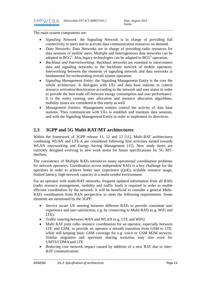
2.4.1 Wired Solutions Among wired backhaul technologies, optical fibre provides a very high performance connection with multi Gigabits per second (Gbps) throughput, for example using Gigabit Passive Optical Network (GPON) architectures. The transmission on the fibre is at present based on specific protocols such as Common Public Radio Interface (CPRI) [8]. The CPRI specifies the internal interface of radio base stations between the Radio Equipment Control (REC) and the Radio Equipment (RE). The REC corresponds to the base station baseband unit that provides the access to the radio network. The RE corresponds to the base station RF unit. The RE provides the analogue and radio frequency functions such as filtering, modulation, frequency conversion and amplification. The REC and RE communicate over a generic interface based on digital I/Q data transfer. In addition to the user plane data, control, and management as well as synchronization signals are exchanged between the REC and the RE. The basic configuration is composed of one REC and one RE connected by a single CPRI link but it can be extended in several ways. For example, several CPRI links may be used to enhance the system capacity as required for large system configurations involving many antennas and carriers. It is required that an I/Q data flow of a certain antenna and a certain antenna-carrier is carried completely by one CPRI link. However, it is allowed that the same antenna-carrier may be transmitted simultaneously over several links. Therefore, the number of physical links is not restricted by the specification. Second, several REs may be served by one REC using the so-called star topology. Third, one RE may be served by multiple RECs. Furthermore, three basic networking topologies may
Deliverable FP7-ICT 608637/D1.2
Date :August 2014 Public
MiWEBA D1.2: Specification of architecture Page 19
be used for the interconnection of REs: Chain topology, Tree topology and Ring topology (see Figure 2-8).
a) Star Topology
b) Chain Topology
c) Tree Topology
d) Ring Topology
Figure 2-8: Networking topologies for the interconnection of REs [8]
2.4.2 Wireless Backhaul Topologies Wireless backhaul is commonly deployed with the following topologies, depending on the scenario and requirements of the operator:
• Point-to-Point (PTP): A mode of operation whereby a link exists between two network entities. Individual point to point links between nodes (i.e. access points and / or gateways) can be interconnected to form chain, tree or ring topologies. PTP links are an excellent way to establish connections between two sites and achieve high data transfer speeds, especially in the case when LOS is available and microwave / mmW radio is used.
• Point-to-Multi-point (PtMP): This approach allows a network entity to transmit/receive data to multiple entities. In cellular systems, a hub transceiver forms multiple links to a number of access points [63]. The total hub capacity is shared among the underlying access points, hence statistical multiplexing gains can be achieved. This solution can be seen as an attractive solution mainly for the low bandwidth requiring points in short distances, making it a good candidate topology for small cells. Comparing to point to point, the NLOS capability of PtMP is better due to the fact that wider antennas are used.
• Mesh: A wireless mesh network is a peer-to-peer, multi-hop wireless network in which participant nodes or access points cooperate to route packets. In this solution, nodes form multiple redundant links to improve resiliency and routing algorithms can be used to find the least cost path taking into account network loading and link outage. Unlike PtP and PtMP topologies, a multitude of paths between source and destination nodes guarantees high network availability in case of node (or link) failures or poor channel conditions.
Deliverable FP7-ICT 608637/D1.2
Date :August 2014 Public
MiWEBA D1.2: Specification of architecture Page 20
3 Multi-RAT architecture
3.1 Definition of general architecture for WP3 and WP5 Work packages 3 and 5 both have tasks focusing on the lower layers (PHY and MAC) of the millimeter-wave access link. This access link and the respective user- or data-plane are embedded in the overall architecture with the higher layers of the mobile radio network. The MiWEBA concept builds on existing standards and therefore integration of the mm-wave link into LTE-Advanced is targeted. On the other hand, existing standards for millimeter-wave communication, such as IEEE 802.11ad for example, can serve as a starting point for these links.
In order to simplify the work in these work packages 3 and 5 on the lower layers a reduced view on the higher layer architecture should be used. With the focus being on the access link this architecture comprises the macro cellular base station, the millimeter-wave small cell base station and the user terminal UE, as shown in Figure 3-1
Figure 3-1: Simplified architecture for WP3 and WP5
The user terminal is connected to the legacy cellular control plane (C-plane) and the millimeter-wave user plane. The mm-wave small cell base station is assumed to be connected to the macro base station via a high capacity and low latency backhaul with no specific assumption on the technology. Multiple user terminals within the range of the small cell base station can also be supported if necessary.
Within work package 5 beamforming or beam steering technologies will be investigated that enable the initiation and tracking of the mm-wave user plane link. Building on these results and the requirements for exchange of control information work package 3 can then investigate the split of the user and control plane.
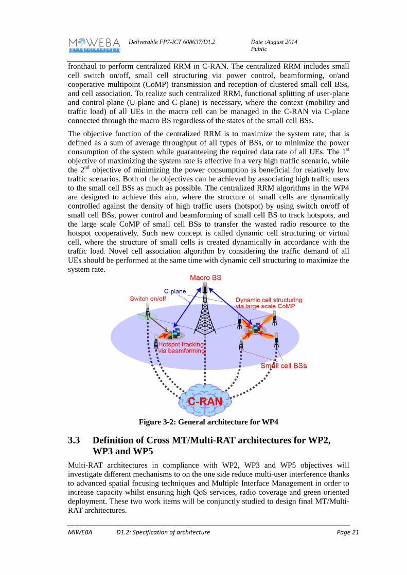
3.2 Definition of general architecture for WP4 Work package 4 (WP4) studies about radio resource management (RRM) for mm-wave overlay HetNet to maximize the performance and efficiency of the system. Figure 3.2 shows the general architecture for WP4, where newly deployed mm-wave small cell base stations (BSs) as well as a legacy macro BS are connected to C-RAN via backhaul or
Deliverable FP7-ICT 608637/D1.2
Date :August 2014 Public
MiWEBA D1.2: Specification of architecture Page 21
fronthaul to perform centralized RRM in C-RAN. The centralized RRM includes small cell switch on/off, small cell structuring via power control, beamforming, or/and cooperative multipoint (CoMP) transmission and reception of clustered small cell BSs, and cell association. To realize such centralized RRM, functional splitting of user-plane and control-plane (U-plane and C-plane) is necessary, where the context (mobility and traffic load) of all UEs in the macro cell can be managed in the C-RAN via C-plane connected through the macro BS regardless of the states of the small cell BSs.
The objective function of the centralized RRM is to maximize the system rate, that is defined as a sum of average throughput of all types of BSs, or to minimize the power consumption of the system while guaranteeing the required data rate of all UEs. The 1st objective of maximizing the system rate is effective in a very high traffic scenario, while the 2nd objective of minimizing the power consumption is beneficial for relatively low traffic scenarios. Both of the objectives can be achieved by associating high traffic users to the small cell BSs as much as possible. The centralized RRM algorithms in the WP4 are designed to achieve this aim, where the structure of small cells are dynamically controlled against the density of high traffic users (hotspot) by using switch on/off of small cell BSs, power control and beamforming of small cell BS to track hotspots, and the large scale CoMP of small cell BSs to transfer the wasted radio resource to the hotspot cooperatively. Such new concept is called dynamic cell structuring or virtual cell, where the structure of small cells is created dynamically in accordance with the traffic load. Novel cell association algorithm by considering the traffic demand of all UEs should be performed at the same time with dynamic cell structuring to maximize the system rate.
Figure 3-2: General architecture for WP4
3.3 Definition of Cross MT/Multi-RAT architectures for WP2, WP3 and WP5
Multi-RAT architectures in compliance with WP2, WP3 and WP5 objectives will investigate different mechanisms to on the one side reduce multi-user interference thanks to advanced spatial focusing techniques and Multiple Interface Management in order to increase capacity whilst ensuring high QoS services, radio coverage and green oriented deployment. These two work items will be conjunctly studied to design final MT/Multi-RAT architectures.
Deliverable FP7-ICT 608637/D1.2
Date :August 2014 Public
MiWEBA D1.2: Specification of architecture Page 22
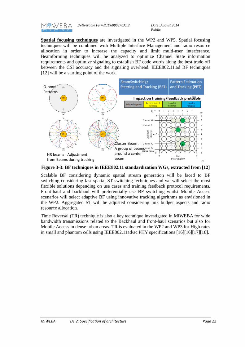
Spatial focusing techniques are investigated in the WP2 and WP5. Spatial focusing techniques will be combined with Multiple Interface Management and radio resource allocation in order to increase the capacity and limit multi-user interference. Beamforming techniques will be analyzed to optimize Channel State information requirements and optimize signaling to establish BF code words along the best trade-off between the CSI accuracy and the signaling overhead. IEEE802.11.ad BF techniques [12] will be a starting point of the work.
Figure 3-3: BF techniques in IEEE802.11 standardization WGs, extracted from [12]
Scalable BF considering dynamic spatial stream generation will be faced to BF switching considering fast spatial ST switching techniques and we will select the most flexible solutions depending on use cases and training feedback protocol requirements. Front-haul and backhaul will preferentially use BF switching whilst Mobile Access scenarios will select adaptive BF using innovative tracking algorithms as envisioned in the WP2. Aggregated ST will be adjusted considering link budget aspects and radio resource allocation.
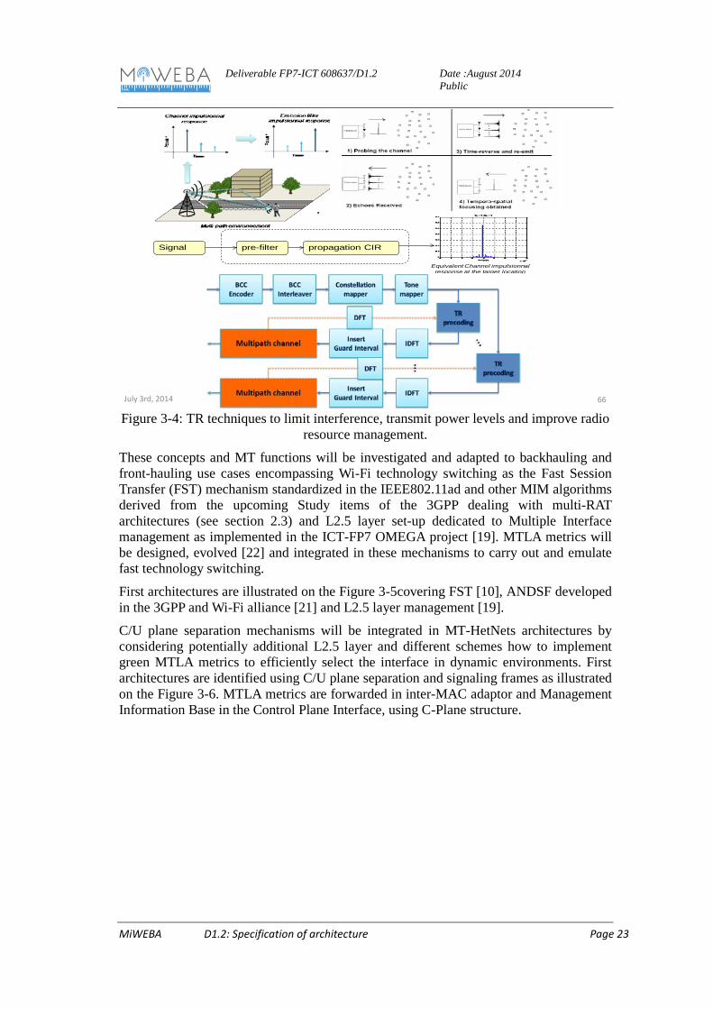
Time Reversal (TR) technique is also a key technique investigated in MiWEBA for wide bandwidth transmissions related to the Backhaul and front-haul scenarios but also for Mobile Access in dense urban areas. TR is evaluated in the WP2 and WP3 for High rates in small and phantom cells using IEEE802.11ad/ac PHY specifications [16][16][17][18].
July 3rd, 2014 69
BeamSwitching/Steering and Tracking (BST)
Pattern Estimation and Tracking (PET)Q-omni
Patterns
HR beams : Adjustment from Beams during tracking
Cluster Beam :A group of beams around a center beam
Impact on training/feedback protocols
Deliverable FP7-ICT 608637/D1.2
Date :August 2014 Public
MiWEBA D1.2: Specification of architecture Page 23
Figure 3-4: TR techniques to limit interference, transmit power levels and improve radio
resource management.
These concepts and MT functions will be investigated and adapted to backhauling and front-hauling use cases encompassing Wi-Fi technology switching as the Fast Session Transfer (FST) mechanism standardized in the IEEE802.11ad and other MIM algorithms derived from the upcoming Study items of the 3GPP dealing with multi-RAT architectures (see section 2.3) and L2.5 layer set-up dedicated to Multiple Interface management as implemented in the ICT-FP7 OMEGA project [19]. MTLA metrics will be designed, evolved [22] and integrated in these mechanisms to carry out and emulate fast technology switching.
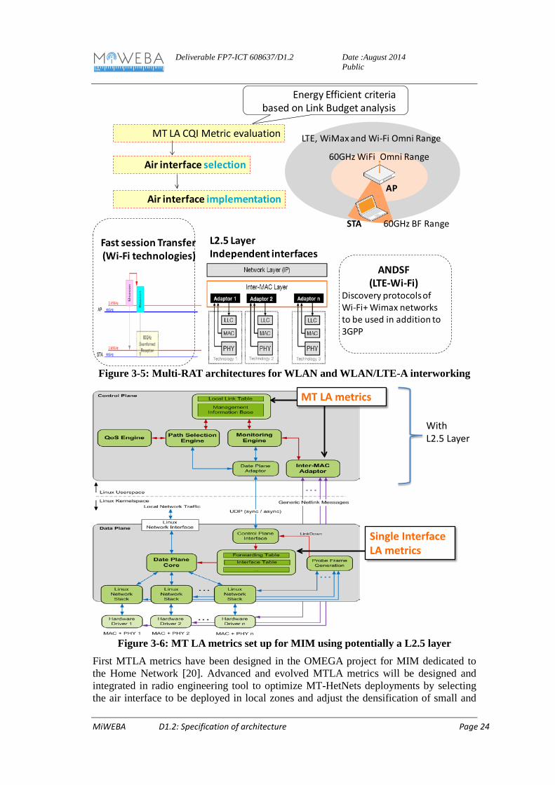
First architectures are illustrated on the Figure 3-5covering FST [10], ANDSF developed in the 3GPP and Wi-Fi alliance [21] and L2.5 layer management [19].
C/U plane separation mechanisms will be integrated in MT-HetNets architectures by considering potentially additional L2.5 layer and different schemes how to implement green MTLA metrics to efficiently select the interface in dynamic environments. First architectures are identified using C/U plane separation and signaling frames as illustrated on the Figure 3-6. MTLA metrics are forwarded in inter-MAC adaptor and Management Information Base in the Control Plane Interface, using C-Plane structure.
July 3rd, 2014 66
Signal propagation CIRpre-filter
Equivalent Channel impulsionnal response at the target location
Deliverable FP7-ICT 608637/D1.2
Date :August 2014 Public
MiWEBA D1.2: Specification of architecture Page 24
Figure 3-5: Multi-RAT architectures for WLAN and WLAN/LTE-A interworking
Figure 3-6: MT LA metrics set up for MIM using potentially a L2.5 layer
First MTLA metrics have been designed in the OMEGA project for MIM dedicated to the Home Network [20]. Advanced and evolved MTLA metrics will be designed and integrated in radio engineering tool to optimize MT-HetNets deployments by selecting the air interface to be deployed in local zones and adjust the densification of small and
60GHz WiFi Omni Range
AP
STA
LTE, WiMax and Wi-Fi Omni Range
60GHz BF Range
Air interface selection
MT LA CQI Metric evaluation
Fast session Transfer(Wi-Fi technologies)
Air interface implementation
L2.5 Layer Independent interfaces
ANDSF(LTE-Wi-Fi)
Discovery protocols of Wi-Fi+ Wimax networks to be used in addition to 3GPP
Energy Efficient criteriabased on Link Budget analysis
MT LA metrics
WithL2.5 Layer
Single Interface LA metrics
Deliverable FP7-ICT 608637/D1.2
Date :August 2014 Public
MiWEBA D1.2: Specification of architecture Page 25
phantom cells in a Multi-RAT architecture. These functionalities will significantly reduce the infrastructure cost, power management depending on the metric used to optimize such infrastructures.
Figure 3-7: Multi-HetNet deployment optimization using system metrics in a radio
engineering tool
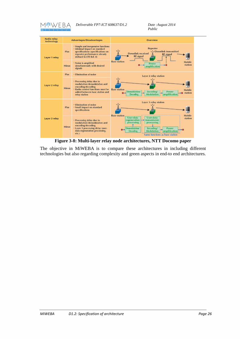
3.4 Deployment mechanisms for relays Deployment scenarios applicable to relay technology and the radio access technology, radio control technology and architecture for achieving the relay technology are now being standardized in 3GPP, layer 3 has been selected for the 3GPP standardization. The NTT docomo paper [23] details these architectures:
• A layer 1 relay consists of relay technology called a booster or repeater implementing Amplifying and Forwarding (AF) functions to relay the information. Signals on the uplink or downlink are amplified including both desired signals and interference and noise. The layer-2 is a Decode and Forward (DF) type of relay technology by which RF signals received are demodulated and decoded and then encoded and modulated again before being sent on to the mobile station. This technique removes noise and interference A better throughput-enhancement can be expected compared with the layer 1 relay. At the same time, the layer 2 relay introduces latency due to DF and EF functions. Retransmission control by Automatic Repeat request (ARQ) and user-data concatenation/segment are specified. This DF relay type is more complex than AF. It well suited to dense urban areas where multi-user interference occurs.
• The layer 3 relay also performs demodulation and decoding of RF signals but then goes on to perform processing (such as ciphering and user-data concatenation/segmentation/reassembly) for retransmitting user data on a potential different radio interface. The layer 3 relay station also features a unique Physical Cell ID (PCI) on the physical layer different than that of the base station. In this way, a mobile station can recognize that a cell provided by a relay station differs from a cell provided by a base station.
techno SelectionTechno 1Techno 2Techno 2+3 …
Multi-technologies
metric and Rx-power in radio
engineering tool
Air interface selection
MT LA CQI Metric evaluation
MT HetNet deployment Optimization
Deliverable FP7-ICT 608637/D1.2
Date :August 2014 Public
MiWEBA D1.2: Specification of architecture Page 26
Figure 3-8: Multi-layer relay node architectures, NTT Docomo paper
The objective in MiWEBA is to compare these architectures in including different technologies but also regarding complexity and green aspects in end-to end architectures.
Deliverable FP7-ICT 608637/D1.2
Date :August 2014 Public
MiWEBA D1.2: Specification of architecture Page 27
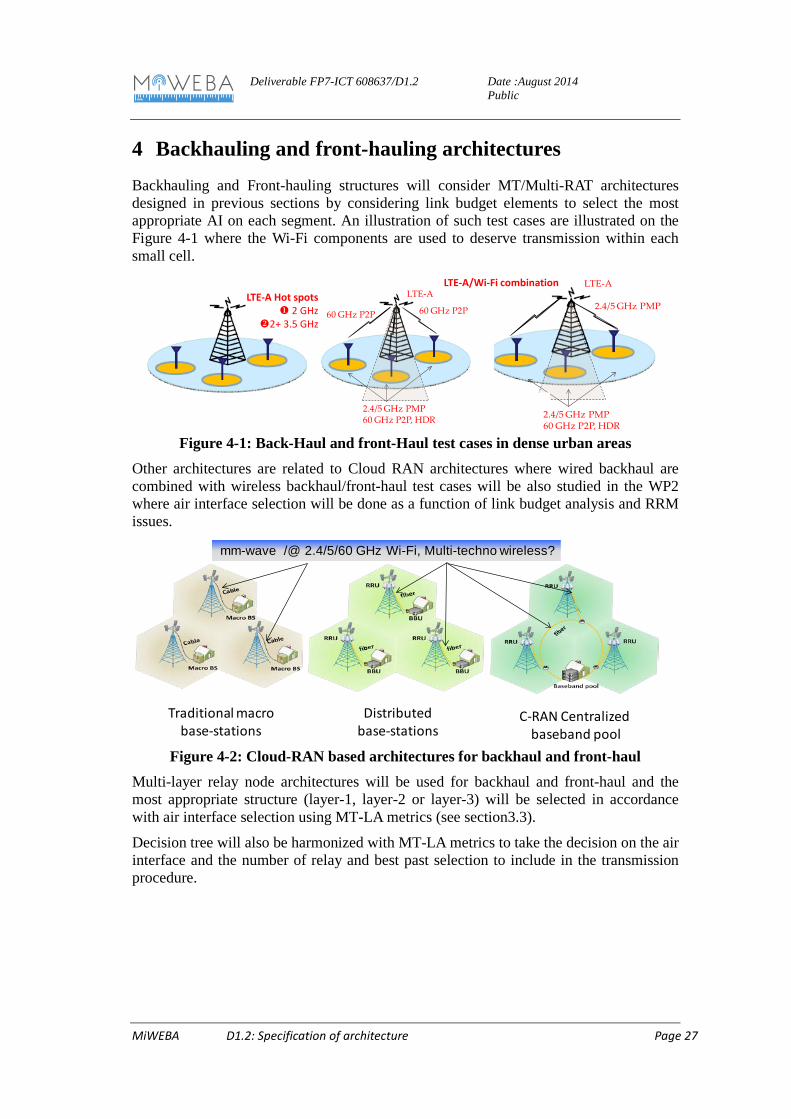
4 Backhauling and front-hauling architectures Backhauling and Front-hauling structures will consider MT/Multi-RAT architectures designed in previous sections by considering link budget elements to select the most appropriate AI on each segment. An illustration of such test cases are illustrated on the Figure 4-1 where the Wi-Fi components are used to deserve transmission within each small cell.
Figure 4-1: Back-Haul and front-Haul test cases in dense urban areas
Other architectures are related to Cloud RAN architectures where wired backhaul are combined with wireless backhaul/front-haul test cases will be also studied in the WP2 where air interface selection will be done as a function of link budget analysis and RRM issues.
Figure 4-2: Cloud-RAN based architectures for backhaul and front-haul
Multi-layer relay node architectures will be used for backhaul and front-haul and the most appropriate structure (layer-1, layer-2 or layer-3) will be selected in accordance with air interface selection using MT-LA metrics (see section3.3).
Decision tree will also be harmonized with MT-LA metrics to take the decision on the air interface and the number of relay and best past selection to include in the transmission procedure.
MiWEBA D1.2: Specification of architecture Page 28
Figure 4-3: Decision tree for Backhauling and Front-hauling
Additionally, CPRI algorithms will be integrated in wireless backhauling to reduce data rate on each link intended to be split between different nodes and phantom cells. It will provide equivalent PSDU data rates as the IEEE802.11ad (several Gbps) compatible with other technologies working in the 5 GHz or LTE-A bands.
Dedicated functions for backhauling and front-hauling will be addressed related to time and resource allocation for downlink and uplink. Aggregated sub-carrier functions will be optimized in relation with time and frequency resource allocation.
Figure 4-4: Self backhauling and resource allocation
Deliverable FP7-ICT 608637/D1.2
Date :August 2014 Public
MiWEBA D1.2: Specification of architecture Page 29
5 Functional Split The MiWEBA architecture introduces a C/U-plane separation which impacts the main network functions in cellular networks. Service access and paging is not performed by every base station, this means that base station managing the request may not be the one in charge of its service. This requires coordination procedure and network reconfiguration according to the information about user. While in legacy 4G networks, Resource selection and activation is basically dependent of local base station scheduling, the C/U-plane separation requires new global algorithms which take into account multiple base stations, their behavior heavily influences the entire network performance. In this perspective, while service request context is basically user CQI and class in legacy 4G networks, MiWEBA C/U-plane split introduces richer context information, increasing the complexity of Context management. Finally, as for Session and Mobility Management, the C/U-plane separation facilitates vertical multi-technology handovers, requires higher coordination for selecting the serving base station.
Taking the approach to the extreme, we can distinguish a logical data network, which provides U-plane, and a logical signaling network implementing C-plane. The role of the signaling network is to provide coverage and manage the UE transition from idle active state, the UE mobility in both idle and active state, and context information. This signaling network is characterized by full coverage guarantees, both in space and in time, low throughput, and small delay tolerance.
5.1 Relevant interfaces and logical controller of the functional split
The entire MiWEBA architecture can be described through functionalities whose managers are in charge of controlling the behavior of the specific task. This decomposition of the entire system into functionality modules allows large freedom and flexibility when defining the network architecture. Envisioned architectures and possible functionality split options are described in Section 5.2.
The following functionalities characterize the base stations implementing MiWEBA C-plane functionalities, i.e., signaling entities:
− Session setup
If there is request to set up a new session, the signaling entity should be responsible for processing the request. This will trigger the “Resource selection and management” feature of the signaling entity, in order to decide whether and how the required session should be served in the most efficient way.
If the session is initiated by the UE, a procedure of random access will be needed. On the other hand, paging is needed for network-initiated session setup.
− Resource selection and management
This is to decide which base station should serve the sessions in the most efficient way. It must estimate which base stations are able to provide coverage for the UE(s) requesting the service and which base station configuration can meet the QoS requirements of the new session as well as the existing sessions.
− Information exchange between signaling entities and base stations
Deliverable FP7-ICT 608637/D1.2
Date :August 2014 Public
MiWEBA D1.2: Specification of architecture Page 30
Signaling entities may exchange information among themselves for different purposes. One example is the exchange of (signaling) traffic load information, which is useful for load balancing either in the radio part or the backhaul part of the network. Another possible example is the exchange of some context information, which has been retrieved in one signaling entities or base station and might also be useful in the other base station.
When a UE is powered on, it needs to synchronize to and camp on under the coverage of signaling entity. During the idle mode, the radio propagation condition between the UE and its serving signaling entity may vary due to UE mobility (the UE moves closer to a neighboring cell) or fading effect (e.g. shadowing). In these cases, the UE may need to reselect another suitable cell to camp on.
− UE location update
UE location area (LA) or tracking area (TA) update message is used to report UE location changes to the core network. One LA or TA usually consists of a group of cells, so LA/TA update is only needed if the UE moves to another LA/TA.
− Broadcasting of system information
System information might be cell-specific, and could include important information (such as cell bandwidth) used by the UEs to access to and operate properly in the network. Most information should be repeatedly broadcast by each signaling entities in order to be acquired even by incoming UEs.
The following functionalities characterize the base stations implementing MiWEBA U-plane functionalities, i.e., data entities:
− Traffic bearer
This is fundamental task for the network service. The most appropriate configuration of base station and UE transceivers indicated by C-plane entities must be actuated and a data link established to transfer user information
− Link-related signaling
This C-plane information about channel control and reporting is strictly related to data exchange and cannot be separated from U-plane. This is crucial information to support the link establishment between UE and base station, both for data and signaling exchange
The communication among base stations, core network and UE implementing different functionalities can occur through interfaces. We can identify the following main communication interfaces:
- UE C-plane interface and UE U-plane interface: the former is used to connect UE to network signaling entities implemented in some of the base stations in order to exchanged signaling information. The latter mainly carries data traffic. Differently from legacy 4G systems, these two interfaces may require two different physical interfaces since C-plane and U-plane information can be accessed via different wireless technologies.
- BS-CN C-plane interface: this interface is used to connect base station to the core network for the exchange of C-plane information. It can be missing in base stations not implementing C-plane functionalities. It is equivalent to S1-MME interface.
Deliverable FP7-ICT 608637/D1.2
Date :August 2014 Public
MiWEBA D1.2: Specification of architecture Page 31
- BS-CN U-plane interface: this interface is used to connect base station to the core network for the exchange of U-plane information. It is always implemented and equivalent to S1-U interface.
- BS-BS C-plane interface and BS-BS U-plane interface: these interfaces are used to directly inter-connect neighboring base stations. Similarly to X2 interfaces, they, respectively, carry signaling and data information. The former used for mobility management and base station coordination, the latter for deviating traffic during handover procedures and multi-flow transmissions. Differently from X2 interface, in MiWEBA, BS-BS C-plane interface could additionally manage the entire C-plane information and replace BS-CN C-plane interface
- BS coordination interface: this interface is used to coordinate the behavior of BSs not directly implementing the entire set of C-plane functionalities. Due to C-/U-plane split, we can have BS only providing U-plane services to UEs. In order to coordinate U-plane activities with C-plane information provided by a different BS, BS coordination interface allows exchanging information among BSs or between CN and BS.
5.2 Functional split options Architectural solutions approaching the C/U-plane split concept have been already considered in standard activities, like in 3GPP dual connectivity approach. In this project we consider different possible split options; the final architecture could include several of these options, which can be implemented in different scenarios to exploit specific advantages.
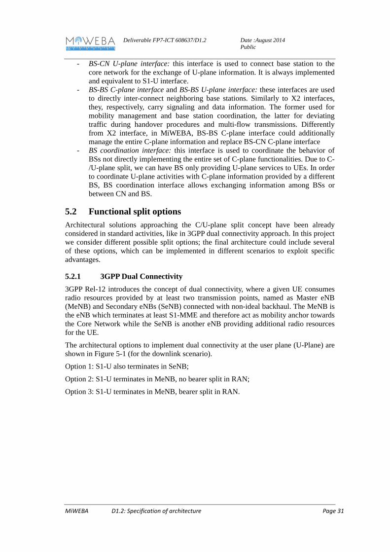
5.2.1 3GPP Dual Connectivity 3GPP Rel-12 introduces the concept of dual connectivity, where a given UE consumes radio resources provided by at least two transmission points, named as Master eNB (MeNB) and Secondary eNBs (SeNB) connected with non-ideal backhaul. The MeNB is the eNB which terminates at least S1-MME and therefore act as mobility anchor towards the Core Network while the SeNB is another eNB providing additional radio resources for the UE.
The architectural options to implement dual connectivity at the user plane (U-Plane) are shown in Figure 5-1 (for the downlink scenario).
Option 1: S1-U also terminates in SeNB;
Option 2: S1-U terminates in MeNB, no bearer split in RAN;
Option 3: S1-U terminates in MeNB, bearer split in RAN.
Deliverable FP7-ICT 608637/D1.2
Date :August 2014 Public
MiWEBA D1.2: Specification of architecture Page 32
Figure 5-1: Bearer split options in dual connectivity [5].
When S1-U terminates at the MeNB, the protocol stack in the SeNB must at least support (re-)segmentation. In fact (re-)segmentation is an operation coupled to the physical interface, and when non-ideal backhaul is used, (re-)segmentation must take place in the same node as the one transmitting the Radio Link Control (RLC) Protocol Data Units (PDUs). Accordingly there are four options to manage the U-Plane:
A. Independent Packet Data Convergence Protocols (PDCPs): this option terminates the U-plane per bearer at a given eNB, and is modelled to realize transmission of one Evolved Packet System (EPS) bearer by one node, but could also support splitting of a single EPS bearer for transmission by MeNB and SeNB with the help of an additional layer. The transmission of different bearers may still happen simultaneously from the MeNB and a SeNB.
B. Master-Slave PDCPs: the S1-U terminates in MeNB with at least part of the PDCP implemented in the MeNB. In case of bearer split, there is a separate and independent RLC bearer, also at UE side, per eNB configured to deliver PDCP PDUs of the PDCP bearer, terminated at the MeNB.
C. Independent RLCs: the S1-U terminates in MeNB with the PDCP layer residing in the MeNB. In case of bearer split, there is a separate and independent RLC bearer, also at UE side, per eNB configured to deliver PDCP PDUs of the PDCP bearer, terminated at the MeNB.
D. Master-Slave RLCs: the S1-U terminates in MeNB with the PDCP layer and part of the RLC layer residing in the MeNB. It requires one RLC entity in the UE for the EPS bearer; on the network side, the RLC functionality is distributed between the nodes involved, with a "slave RLC" operating in the SeNB. In downlink, the slave RLC takes care of the delay-critical RLC operation needed at the SeNB: it receives from the master RLC at the MeNB readily built RLC PDUs (with Sequence Number already assigned by the master) that the master has assigned for transmission by the slave, and transmits them to the UE. The custom-fitting of these PDUs into the grants from the MAC scheduler is achieved by re-using the currently defined re-segmentation mechanism.
From the Radio Resource Control (RRC) perspective, at least three functions are impacted by the dual connectivity concept:
a. Small cell layer's common radio resource configurations;
Option 3Option 1
MeNB
SeNB
EPS bearer #1
EPS bearer #2
UE
S-GW
Option 2
MeNB
SeNB
EPS bearer #1
EPS bearer #2
UE
S-GW
MeNB
EPS bearer #1
SeNB
EPS bearer #2
UE
S-GW
Deliverable FP7-ICT 608637/D1.2
Date :August 2014 Public
MiWEBA D1.2: Specification of architecture Page 33
b. Small cell layer's dedicated radio resource configurations; c. Measurement and mobility control for small cell layer.
Two main architectural options can be considered to manage the RRC in dual connectivity Figure 5-2:
Option 1-Centralized RRC: The MeNB generates the final RRC messages to be sent towards the UE after the coordination of RRM functions between MeNB and SeNB. The UE RRC entity sees all messages coming only from one entity (in the MeNB) and the UE only replies back to that entity.
Option 2-Distributed RRC: MeNB and SeNB generate RRC messages to be sent towards the UE after the coordination of RRM functions between MeNB and SeNB.
Figure 5-2: Radio Interface C-plane architecture alternatives for dual
connectivity[5].
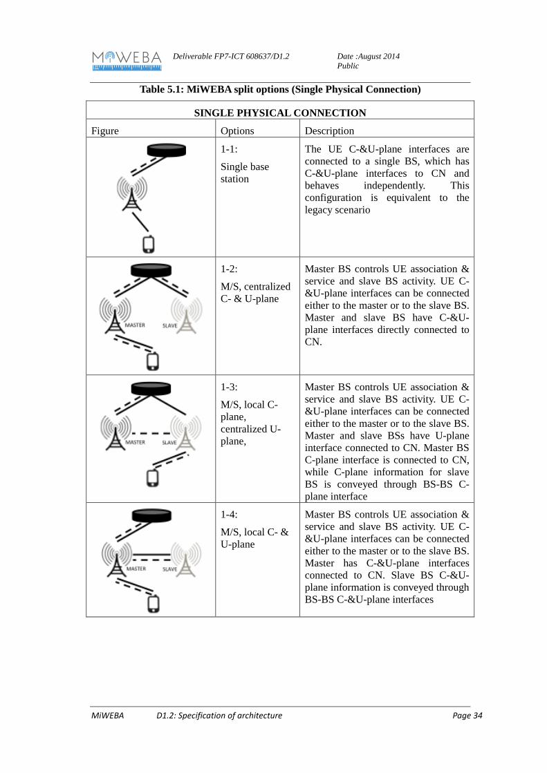
5.2.2 MiWEBA split options The first set of split option requires a single physical connection between UEs and networks. In this set we have a further distinction between master-slave base stations and peer base stations. In the former, one base station has a master role for C-plane information and commands slave base station, in the latter, each base station has a similar role and they coordinate to share the signaling load.
The considered options are described in the following table (solid black lines connect U-plane interfaces, while dashed black lines connect C-plane interfaces).
Control Plane Option 1
SeNB
Control Plane Option 2
Uu
Xn
MeNB
RRC
UE
RRC
MeNB
SeNB
UE
RRC
Anchor RRC
AssistingRRC
Uu
Uu
Xn
Uu
Deliverable FP7-ICT 608637/D1.2
Date :August 2014 Public
MiWEBA D1.2: Specification of architecture Page 34
The UE C-&U-plane interfaces are connected to a single BS, which has C-&U-plane interfaces to CN and behaves independently. This configuration is equivalent to the legacy scenario
1-2:
M/S, centralized C- & U-plane
Master BS controls UE association & service and slave BS activity. UE C-&U-plane interfaces can be connected either to the master or to the slave BS. Master and slave BS have C-&U-plane interfaces directly connected to CN.
1-3:
M/S, local C-plane, centralized U-plane,
Master BS controls UE association & service and slave BS activity. UE C-&U-plane interfaces can be connected either to the master or to the slave BS. Master and slave BSs have U-plane interface connected to CN. Master BS C-plane interface is connected to CN, while C-plane information for slave BS is conveyed through BS-BS C-plane interface
1-4:
M/S, local C- & U-plane
Master BS controls UE association & service and slave BS activity. UE C-&U-plane interfaces can be connected either to the master or to the slave BS. Master has C-&U-plane interfaces connected to CN. Slave BS C-&U-plane information is conveyed through BS-BS C-&U-plane interfaces
Deliverable FP7-ICT 608637/D1.2
Date :August 2014 Public
MiWEBA D1.2: Specification of architecture Page 35
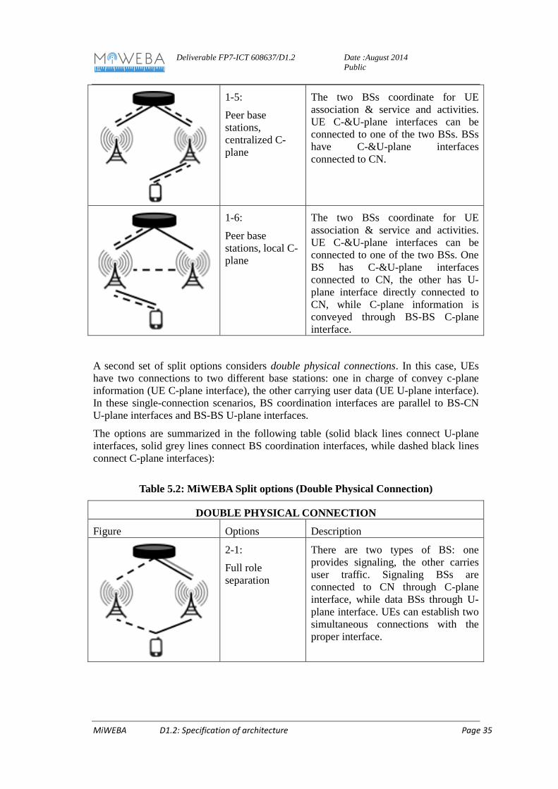
1-5:
Peer base stations, centralized C-plane
The two BSs coordinate for UE association & service and activities. UE C-&U-plane interfaces can be connected to one of the two BSs. BSs have C-&U-plane interfaces connected to CN.
1-6:
Peer base stations, local C-plane
The two BSs coordinate for UE association & service and activities. UE C-&U-plane interfaces can be connected to one of the two BSs. One BS has C-&U-plane interfaces connected to CN, the other has U-plane interface directly connected to CN, while C-plane information is conveyed through BS-BS C-plane interface.
A second set of split options considers double physical connections. In this case, UEs have two connections to two different base stations: one in charge of convey c-plane information (UE C-plane interface), the other carrying user data (UE U-plane interface). In these single-connection scenarios, BS coordination interfaces are parallel to BS-CN U-plane interfaces and BS-BS U-plane interfaces.
The options are summarized in the following table (solid black lines connect U-plane interfaces, solid grey lines connect BS coordination interfaces, while dashed black lines connect C-plane interfaces):
There are two types of BS: one provides signaling, the other carries user traffic. Signaling BSs are connected to CN through C-plane interface, while data BSs through U-plane interface. UEs can establish two simultaneous connections with the proper interface.
Deliverable FP7-ICT 608637/D1.2
Date :August 2014 Public
MiWEBA D1.2: Specification of architecture Page 36
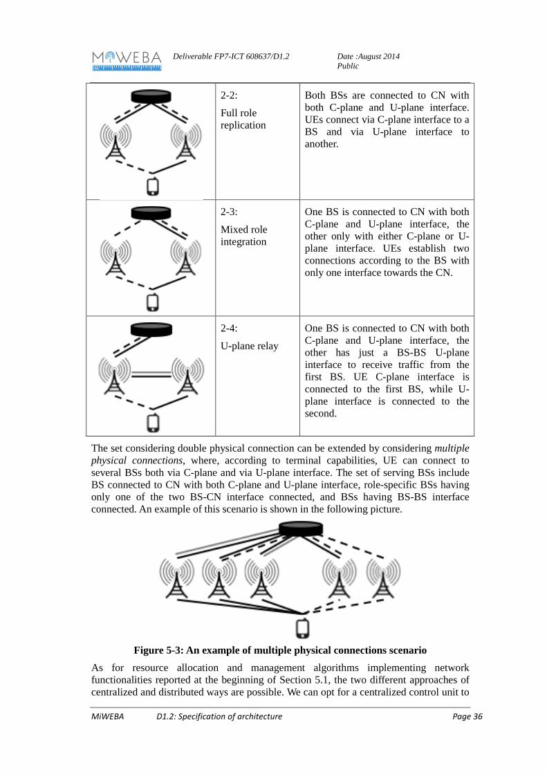
2-2:
Full role replication
Both BSs are connected to CN with both C-plane and U-plane interface. UEs connect via C-plane interface to a BS and via U-plane interface to another.
2-3:
Mixed role integration
One BS is connected to CN with both C-plane and U-plane interface, the other only with either C-plane or U-plane interface. UEs establish two connections according to the BS with only one interface towards the CN.
2-4:
U-plane relay
One BS is connected to CN with both C-plane and U-plane interface, the other has just a BS-BS U-plane interface to receive traffic from the first BS. UE C-plane interface is connected to the first BS, while U-plane interface is connected to the second.
The set considering double physical connection can be extended by considering multiple physical connections, where, according to terminal capabilities, UE can connect to several BSs both via C-plane and via U-plane interface. The set of serving BSs include BS connected to CN with both C-plane and U-plane interface, role-specific BSs having only one of the two BS-CN interface connected, and BSs having BS-BS interface connected. An example of this scenario is shown in the following picture.
Figure 5-3: An example of multiple physical connections scenario
As for resource allocation and management algorithms implementing network functionalities reported at the beginning of Section 5.1, the two different approaches of centralized and distributed ways are possible. We can opt for a centralized control unit to
Deliverable FP7-ICT 608637/D1.2
Date :August 2014 Public
MiWEBA D1.2: Specification of architecture Page 37
which all base stations refer to, or we can have cooperation among base stations in physical proximity in order to carry out a task. We can also have Virtual Network Functions (VNF), whose executions is migrated among sets of base stations according load and traffic distribution. Finally, the solution that appears to be the most promising is a hybrid solution where some of the functions are implemented in a centralized manner, maybe with the help of C-RAN or VNF solutions, and some others follow a distributed approach to improve scalability.
5.3 Evaluation of constraints and foreseen gains The advantages of the proposed split architecture are:
• Flexibility to integrate different radio technologies in the network operation • Local C-&U-planes (see previous section) allow to better design network
topologies according to bandwidth and delay characteristics of links that can be established
• Solutions with peer base stations and/or multiple physical connections increase the robustness of the network by easing off user and resource re-allocation
• Better mobility management • Higher architectural flexibility by supporting centralized and distributed
solutions • Smarter user access policies and procedures • Easier transition to infrastructure sharing solutions: sharing of C-plane
infrastructure and operation on own U-plane infrastructure.
These advantages, however, brings in higher complexity and the need of better coordination among network devices. In addition, richer user and network context is required to efficiency allocate available resources.
Critical constraining issues to be addressed to enable the proposed solutions are:
- Management of signaling translation with legacy technologies - Integration of C-plane interfaces carried over different technologies - Smart resource allocation algorithms to achieve high energy and spectral
efficiency - Definition of the set of functionalities to be implemented in a centralized or a
distributed manner.
Deliverable FP7-ICT 608637/D1.2
Date :August 2014 Public
MiWEBA D1.2: Specification of architecture Page 38
6 Conclusions This public report proposes specifications of architectures referred by the MiWEBA project, which are divided into three points of view. First one is the Multi-RAT/MT architecture considering technical challenges to solve and first research items to investigate in order to design mm-wave overlay MT HetNets architectures. The second one is the backhauling and fronthauling architecture in order to realize multi RAT control and implement generic MT/Multi-RAT architectures previously described and the last one is the C/U separation architecture.
In the Multi-RAT architecture, MTLA metrics are integrated in radio engineering tool to optimize MT-Het Nets deployments by selecting the air interface to be deployed in local zones and adjust the densification of small and phantom cells in global MT HetNets architectures. This function will significantly reduce transmit power levels, ensure QoS in End-to-End architectures and will allow to alleviate the 5G challenge keeping unchanged the infrastructure costs with higher capacity. Different Multiple Interface Management architectures are proposed based on Fast Session Transfer protocols, additional layer (L2.5) to implement such metrics and emulate Multiple Interface Management and evolved ANDSF mechanisms. These functions are integrated C/U plane separation schemes.
In the backhauling and front-hauling architecture, different architectures are proposed integrating generic MT/multi-RAT mechanisms described in the section 3. Additionally, multi-layer relay node architectures are described and will be assessed in the WP2, when they are combined with MT radio link segments into multi-hop schemes. Best path selection will be also examined combined with MIM. Self-backhauling integrating time and frequency resource allocation will be addressed. Finally, CPRI algorithms will be considered for high throughput wireless backhaul and front-haul schemes.
In the C/U-plane separation architecture where C/U separation functions are detailed, two sets of split option are defined as MiWEBA split options in this report. One is a single physical connection and another is double physical connections. The former includes six options (Single base station, M/S centralized C/U-plane, M/S local C-Plane, centralized U-plane, M/S local C/U-plane, peer base stations centralized C-plane, and Peer base stations local C-plane) The latter includes four options(Full role separation, Full role replication, and Mixed role integration, U-Plane relay). The set considering double physical connection can be extended by considering multiple physical connections.
The solution that appears to be the most promising is a hybrid solution where some of the functions are implemented in a centralized manner, maybe with the help of C-RAN or VNF solutions, and some others follow a distributed approach to improve scalability.
Deliverable FP7-ICT 608637/D1.2
Date :August 2014 Public
MiWEBA D1.2: Specification of architecture Page 39
December 2013, available at http://www.miweba.eu [2] S. Parkvall, A. Furuskar, E. Dahlman, Evolution of LTE toward IMT-advanced,
IEEE Communications Magazine 49 (2) (2011) 84–91. [3] Huawei Technologies, The second phase of LTE-Advanced,
http://huawei.com/ilink/en/download/HW259010/, 2013 [4] 3GPP TS 36.300, Technical Specification Group Radio Access Network; Evolved
Universal Terrestrial Radio Access (E-UTRA) and Evolved Universal Terrestrial Radio Access Network (E-UTRAN); Overall description; Stage 2 (Release 11), 2013.
[5] 3GPP TR 36.842, Technical Specification Group Radio Access Network; Study on Small Cell enhancements for E-UTRA and E-UTRAN; Higher layer aspects (Release 12), December 2013.
[7] NGMN Alliance, "Small cell backhaul requirements," White Paper, June 2012. [8] Common Public Radio Interface (CPRI), “Interface Specification”, v5.0 (2011-09-
21), Sept. 2011 http://www.cpri.info. [9] P. Xing, L. Yang, P. Demestichas, A. Georgakopoulos, WWRF Outlook White
paper, “Multi-RAT Network Architecture”, WG C, November 2013. [10] IEEE 802.11-10/491r2 document, “Fast Session Transfer”, IEEE802.11.ac group,
May 2010. [11] Overview of 3GPP Release 13 V0.0.6 (2014-06),
http://www.3gpp.org/ftp/Information/WORK_PLAN/Description_Releases/ [12] I. Lakkis, S. Kato, C. Ngo, J.P.K Gilb, “IEEE 802.15.3c Beamforming overview”,
IEEE-802.11-09/355r0 document, March 2009. [13] IEEE P802.11ac™/D5.0 draft, Part 11: Wireless LAN Medium Access Control
(MAC) and Physical Layer (PHY) specifications- Amendment 4: Enhancements for Very High Throughput for Operation in Bands below 6 GHz,January 2013
[14] IEEE P802.11ad™Standard for Information Technology – Part 11: Wireless LAN Medium Access Control (MAC) and Physical Layer (PHY) Specifications -Enhancements for Very High Throughput in the 60 GHz Band.
[15] 3GPP TR 32.834 V11.0.0 (2012-01) 3rd Generation Partnership Project;Technical Specification Group Services and System Aspects;Study on Operations, Administration and Maintenance (OAM) aspects of inter-Radio-Access-Technology (RAT) energy saving (Release 11).
[16] M.-A. Bouzigues, I. Siaud, M. Hélard, and A.-M. Ulmer-Moll, “Turn Back the Clock: Time Reversal for Green Radio Communications,” IEEE Vehicular Technology Magazine, Vol. 8, No. 1, pp 49-56, March, 2013.
[17] M.-A. Bouzigues, I. Siaud, M. Hélard, and A.-M. Ulmer-Moll, “On the use of Time-Reversal for Packet-Switching in Green Communications,” 2013 IEEE 9th International Conference on Wireless and Mobile Computing, Networking and Communications (WiMob), Lyon, France, October 7-9, 2013.
[18] M.-A. Bouzigues, I. Siaud, M. Hélard, and A.-M. Ulmer-Moll, “Green improvements of IEEE 802.11 directional multi-gigabit physical layer specifications,” 10th Conference on Ph.D. Research in Microelectronics and Electronics (PRIME 2014), Grenoble, France, June 30-July 3, 2014.
MiWEBA D1.2: Specification of architecture Page 40
[19] ICT FP7 OMEGA project, Deliverable 5.5 “Inter-MAC Final Evaluation Report”, March 2011.
[20] ICT FP7 OMEGA project, Deliverable 2.7 “Radio Final Evaluation Report”, March 2011
[21] “The case for ANDSF”, White paper published by Smith Software Inc, 2013. [22] A.M. Ulmer-Moll, I. Siaud, “A green link budget CQI metric for multi-RAT HET-
NETS”, software demo, International conference TIA’2012, Green Touch ,Dallas meeting, June 2012.
[23] Special Articles on LTE-Advanced Technology -Ongoing Evolution of LTE toward IMT-Advanced-, M. Iwamura, H. Takahashi, S. Nagata, “Relay Technology in LTE-Advanced”, NTT DOCOMO Technical Journal Vol. 12 No. 2.