Free Convective Flow of Immiscible Permeable Fluids in a Vertical
Channel with First Order Chemical Reaction
J. Prathap Kumar1, J. C. Umavathi2, Shreedevi Kalyan3
1 Professor, Department of Mathematics, Gulbarga University, Kalaburagi, Karnataka, India 2 Professor, Department of Mathematics, Gulbarga University, Kalaburagi, Karnataka, India
3 Research Scholar, Department of Mathematics, Gulbarga University Kalaburagi, Karnataka, India.
ratio and conductivity ratio. In addition, closed form
expressions for volumetric flow rate, Nusselt number,
species concentration and total energy added to the flow
are also derived. It is also found that both analytical and
numerical solutions agree very well for small values of
perturbation parameter.
Key Words: Chemical reaction, porous medium,
perturbation method, finite difference method.
1. INTRODUCTION Convection in porous media is applied in utilization of geothermal energy, the control of pollutant spread in groundwater, the design of nuclear reactors, compact heat exchangers, solar power collectors, heat transfer associated
with the deep storage of nuclear waste and high performance insulators for buildings. Considerable progress in this area was made by Nield and Bejan [1], Kaviany [2] and Vafai and Tien [3] also analyzed the effects of a solid boundary and the inertial forces on flow and heat transfer in porous media. The coupled fluid flow and heat transfer problem in a fully developed composite region of two parallel plates filled with Brinkman-Darcy porous medium was analytically investigated by Kaviany [4]. Rudraiah and Nagraj [5] studied the fully developed free-convection flow of a viscous fluid through a porous medium bounded by two heated vertical plates. Beckerman [6] studied natural convection in vertical enclosure containing simultaneously fluid and porous layers. Singh et al. [7] analyzed heat and mass transfer phenomena due to natural convection in a composite cavity containing a fluid layer overlying a porous layer saturated with the same fluid, in which the flow in the porous region was modeled using Brinkman-Forchheimer extended Darcy model that includes both the effect of macroscopic shear (Brinkman effect) and flow inertia (Forchheimer effect). Forced convection in composite channel is a subject of intensive investigation. This is due to the rapid development of technology and numerous modern thermal applications relevant to this area such as cooling of microelectronic devices. Poulikakos and Kazmierczak [8] presented analytical solutions for forced convection flow in ducts where the central part is occupied by clear fluid and the peripheral part is occupied by a Brinkman-Darcy fluid-saturated porous medium. The results of Poulikakos and and Kazmierczak [8] were extended by Kuznetsov [9] to account for the Forchheimer (quadratic drag) effects. Prasad [10] have made an excellent review for composite systems. Alzami and Vafai [11] reviewed different types of interface conditions between a porous medium and fluid layer.
Some novel designs of heat sinks for cooling microelectronic devices utilize highly porous materials such as aluminum foam (Paek et al. [12]). Nield and Kuznetsov [13] considered a forced convection problem in a channel whose center is occupied by a layer of isotropic porous medium (porous layer 1) and whose peripheral part is occupied by another layer of isotropic porous medium (porous layer 2), each of the layers with its own permeability and thermal conductivity. They utilized the Darcy law for the flow in porous layers. Malashetty et al. [14-16] studied two-fluid flow and heat transfer in an inclined channel containing a porous-fluid layer and composite porous medium. Recently, Umavathi et al. [17-23], Umavathi and Manjula [24], Umavathi [25] and Prathap Kumar et al. [26, 27] studied mixed convection in a vertical porous channel. Combined heat and mass transfer problems with a chemical reaction are of importance in many processes and have received a considerable amount of attention in recent years. Such as drying, evaporation at the surface of a water body, energy transfer in a wet cooling tower and the flow in a desert cooler, heat and mass transfer occurs simultaneously. Natural convection processes involving the combined mechanisms are also encountered in many natural processes, such as evaporation, condensation and agriculture drying and in many industrial applications, such as the curing of plastics, cleaning and chemical processing of materials relevant to the manufacture of the printed circuitry and the manufacture of pulp-insulated cables. In many chemical engineering processes, chemical reactions take place between a foreign mass and a working fluid mass which moves due to the stretch of a surface. The order of the chemical reactions depends on several factors. One of the simplest chemical reactions is the first order reaction in which the rate of the reaction is directly proportional to the species concentration. Chamkha [28] studied the analytical solutions for heat and mass transfer by the laminar flow of a Newtonian, viscous, electrically conducting and heat generating /absorbing fluid on a continuously moving vertical permeable surface in the presence of a magnetic field and the first order chemical reaction. Muthucumaraswamy and Ganeshan [29] studied the numerical solution for the transient natural convection flow of an incompressible viscous fluid past an impulsively started semi-infinite isothermal vertical plate with the mass diffusion, taking into account a homogeneous chemical reaction of the first order. The analytical solution of the free convection heat and mass transfer from a vertical plate embedded in a fluid-saturated porous medium with the constant wall temperature and concentration was obtained by Singh and Queeny [30]. The heat and mass transfer characteristics of the natural convection about a vertical surface embedded in a saturated porous medium subjected
to a chemical reaction taking into account the Soret and Dufour effects was analyzed by Postelnicu [31]. Prathap Kumar et al. [32-34] studied the effect of homogenous and heterogeneous reaction on the dispersion of a solute for an immiscible fluid. Keeping in view the wide area of practical applications on multi fluid flow and effects of chemical reaction as mentioned, the objective of this study is to investigate the heat and mass transfer of two immiscible permeable fluids between vertical parallel plates.
2. MATHEMATICAL FORMULATION OF THE PROBLEM
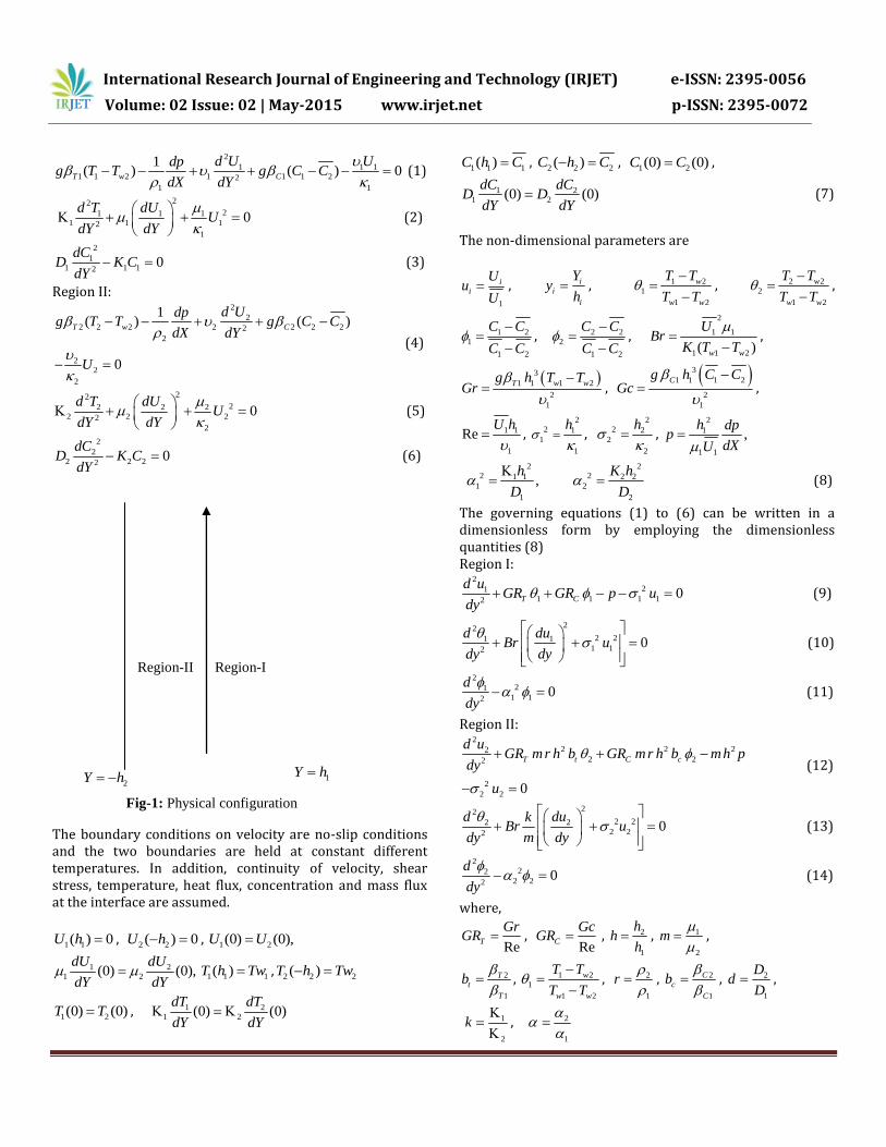
The geometry under consideration illustrated in figure 1, consists of two infinite parallel plates maintained at equal or constant temperature, taking X axis along the midsection of channel and Y axis perpendicular to walls. The region-I
1(0 )Y h is filled with a homogeneous isotropic porous
concentration expansion coefficient1C and diffusion
coefficient1D . The region-II
2( 0)h Y is filled with
another homogeneous isotropic porous material having permeability
2 . This region is saturated with different
viscous fluid of density2 , viscosity
2 , thermal
conductivity2K , thermal expansion coefficient
2T ,
concentration expansion coefficient 2C and diffusion
coefficient2D . The fluids are assumed to have constant
property except the density in the buoyancy term in the momentum equation. A fluid rises in the channel driven by buoyancy force. The temperature properties of both the fluids are assumed to be constant. We consider the fluids to be incompressible; flow is steady, laminar and fully developed. It is assumed that the fluid viscosity and Brinkman viscosity (i. e effective viscosity) are same. The flow in both the regions is assumed to be driven by a
common constant pressure gradient dp dX and
temperature gradient 1 2w wT T T . It is also assumed
that at any given instant, the temperature of the fluid and the temperature of solid are same. The temperature and concentration of boundary at 1Y h is 1wT and 1wC , while at
2Y h is 2wT and 2wC respectively.
Under these assumptions, the governing equations of motion, energy and concentration for incompressible fluids yields Region I:
The boundary conditions on velocity are no-slip conditions and the two boundaries are held at constant different temperatures. In addition, continuity of velocity, shear stress, temperature, heat flux, concentration and mass flux at the interface are assumed.
1 1( ) 0U h , 2 2( ) 0U h , 1 2(0) (0),U U
1 2
1 2(0) (0),dU dU
dY dY 1 1 1( )T h Tw , 2 2 2( )T h Tw
1 2(0) (0)T T , 1 2
1 2(0) (0)dT dT
dY dY
1 1 1( )C h C , 2 2 2( )C h C ,
1 2(0) (0)C C ,
1 2
1 2(0) (0)dC dC
D DdY dY
(7)
The non-dimensional parameters are
1
i
i
Uu
U , i
i
i
Yy
h , 1 2
1
1 2
w
w w
T T
T T
, 2 2
2
1 2
w
w w
T T
T T
,
1 2
1
1 2
C C
C C
, 2 2
2
1 2
C C
C C
,
2
1 1
1 1 2( )w w
UBr
K T T
,
3
1 1 1 2
2
1
T w wg h T TGr
,
3
1 1 1 2
2
1
Cg h C CGc
,
1 1
1
ReU h
,
2
2 1
1
1
h
,
2
2 2
2
2
h
,
2
1
1 1
,h dp
pdXU
2 2
2 21 1 2 2
1 2
1 2
,h K h
D D
(8)
The governing equations (1) to (6) can be written in a dimensionless form by employing the dimensionless quantities (8) Region I:
The boundary and interface conditions in non-dimensional form become
1(1) 0u , 2 ( 1) 0u ,
1 2(0) (0)u u , 1 21(0) (0)
du du
dy mh dy
1(1) 1 , 2 ( 1) 0 ,
1 2(0) (0) , 1 21(0) (0)
d d
dy kh dy
1(1) 1 , 2 ( 1) 0 ,
1 2(0) (0) , 1 2(0) (0)d dd
dy h dy
(15)
3. METHOD OF SOLUTIONS 3.1 Perturbation Method Equations (9) to (14) are coupled and highly non-linear equations because of viscous and Darcy dissipation terms, hence exact solutions cannot be found. The approximate analytical solutions can be found using regular perturbation method. The Brinkman number can be exploited as the perturbation parameter. Therefore the solutions are assumed in the form
2
0 1 2( ) ( ) ( ) ( ) ...i i i iu y u y Bru y Br u y (16) 2
0 1 2( ) ( ) ( ) ( ) ...i i i iy y Br y Br y (17)
Using equations (16) and (17) in equations (9), (10), (12) and (13) and equating the coefficients of like powers of Br to zero and one we determine zeroth and first order equations as follows Region I: Zeroth order equations:
2
10
20
d
dy
(18)
2
210
10 1 10 120T C
d uGR GR p u
dy (19)
First order equations: 22
2 21011
1 1020
dudu
dydy
(20)
2
211
11 11 120T
d uGR u
dy (21)
Region II: Zeroth order equations:
2
20
20
d
dy
(22)
2
2 2 220
20 22
2
2 20 0
T t C c
d uGR mr h b GR mr h b mh p
dy
u
(23)
First order equations:
22
2 22021
2 2020
dud ku
m dydy
(24)
2
2 221
21 2 2120T t
d uGR m r h b u
dy (25)
The corresponding boundary and interface conditions as given in equation (15) can be written as, Zeroth order boundary and interface conditions
10 1 0u , 20 1 0u , 10 200 0u u ,
10 201(0) (0)
du du
dy mh dy
10 (1) 1 , 20 ( 1) 0 ,
10 20(0) (0) ,
10 201(0) (0)
d d
dy kh dy
(26)
First order boundary and interface conditions
11(1) 0u , 21( 1) 0u , 11 21(0) (0)u u ,
11 211(0) (0)
du du
dy mh dy ,
11(1) 0 , 21( 1) 0 ,
11 21(0) (0) , 11 211(0) (0)
d d
dy kh dy
(27)
The solutions for equations (11) and (14) are obtained directly
1 1 1 2 1( ) ( )B Cosh y B Sinh y (28)
2 3 2 4 2( ) ( )B Cosh y B Sinh y (29)
The solutions of zeroth and first order equations (18) to (25) are obtained by using boundary and interface conditions as defined in equations (26) and (27) respectively and are given by
Heat Transfer The wall heat transfer expression in terms of the Nusselt number becomes
11d
Nu hdy
at 1y
21_ 1
dNu
h dy
at 1y
1 1 1 2 3 4 1 1
5 1 1 1 6 1 1 7 1
1 8 1 1 9 1 10 1 1
11 1 1 12 1 1 1
13 1 1 1 14 1
(1 ) 2 3 4 ( )
( ) 2 (2 ) 2 (2 )
2 (2 ) 2 (2 ) ( )
( ) ( ) ( )
( ) ( ) (
Nu h c Br E q q q q Sinh
q Cosh q Sinh q Cosh
q Sinh q Cosh q Sinh
q Cosh q Sin h Cosh
q Co sh Sinh q S inh
1
1 15 1 1 1
16 1 1 1 1 17 1 1 1 1
18 1 1 1 1
19 1 1 1 1
)
( ) ( ) ( )
( ) ( ) ( ) ( )
( ) ( )
( ) ( )
Cosh q C osh Si nh
q Sinh q Sinh
q Cosh
q Cosh
(38)
3 3 1 2 3 4 2 2
5 2 2 2 6 2 2 7 2
2 8 2 2 9 2 10 2 2
11 2 2 12 2 2 2
13 2 2 2 14 2 2
_ 1 1 2 3 4 ( )
( ) 2 (2 ) 2 (2 )
2 (2 ) 2 (2 ) ( )
( ) ( ) ( )
( ) ( ) (
Nu h c Br E F F F F Sinh
F Cosh F Sinh F Cosh
F Sinh F Cosh F Sinh
F Cosh F Sinh C osh
F Cosh Sin h F Sin h
2 15 2 2 2
16 2 2 2 2 17 2 2 2 2
18 2 2 2 2 19 2 2 2 2
)
( ) ( ) ( )
( ) ( ) ( ) ( )
( ) ( ) ( ) ( )
C osh F Cosh S inh
F Sinh F Sinh
F Cosh F Cosh
(39)
The constants appeared in the solutions are not presented as they can be obtained while finding the solutions. The dimensionless total volume flow rate is given by
1 2Qv Qv Qv (40)
where
1 0
1 1 2 20 1
,Qv u dy Qv u dy
The dimensionless total heat rate added to the fluid is given by
1 2E E E (41)
where
1 0
1 1 1 2 2 20 1
,E u dy E u dy
The dimensionless total species rate added to the fluid is given by
Equations (29) to (42) are evaluated for different values of the governing parameters and the results are presented graphically.
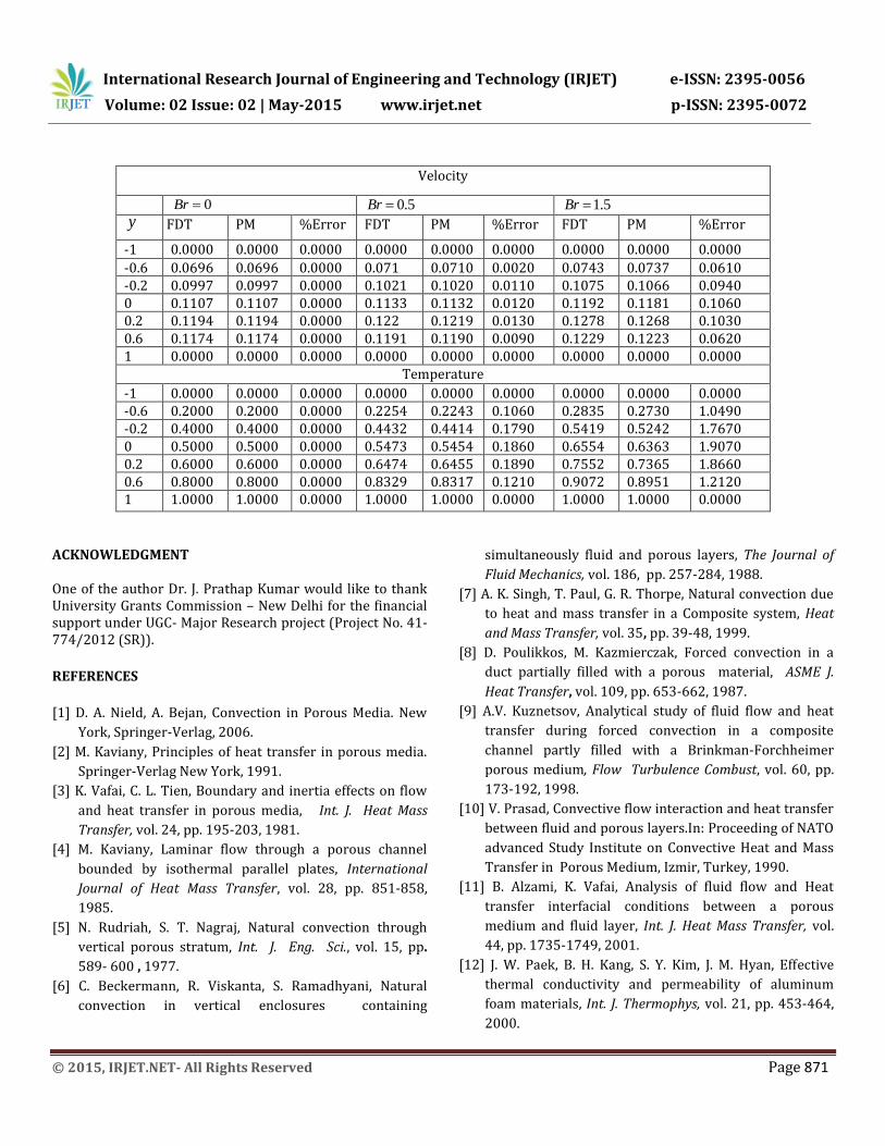
3.2 Finite Difference Method The approximate analytical solutions obtained in the subsection are valid for values of Brinkman number less then one. However in many practical problems especially when viscous dissipation dominates, the Brinkman number takes the values greater than one. In such situations it is required to find the approximate solutions numerically. The governing equations (1) to (6) with the boundary and interface conditions (15) are solved using FDM. In numerical iterations, computation domain is divided into a uniform grid system. The second derivative and the squared – first derivatives terms are discritized with central difference of second order accuracy. By replacing the derivatives with the corresponding finite difference approximation, we obtain a set of n algebraic equations, where n is the number of
divisions from -1 to 1.To validate the present numerical method, computed solutions are compared with analytical solutions. The numerical and analytical solutions agree very well in the absence of Brinkman number and as the Brinkman number increases, error between FDM and PM also increases. The solutions obtained by FDM and PM are depicted in Table1 and percentage error between FDM and PM is also evaluated.
4. RESULTS AND DISCUSSION
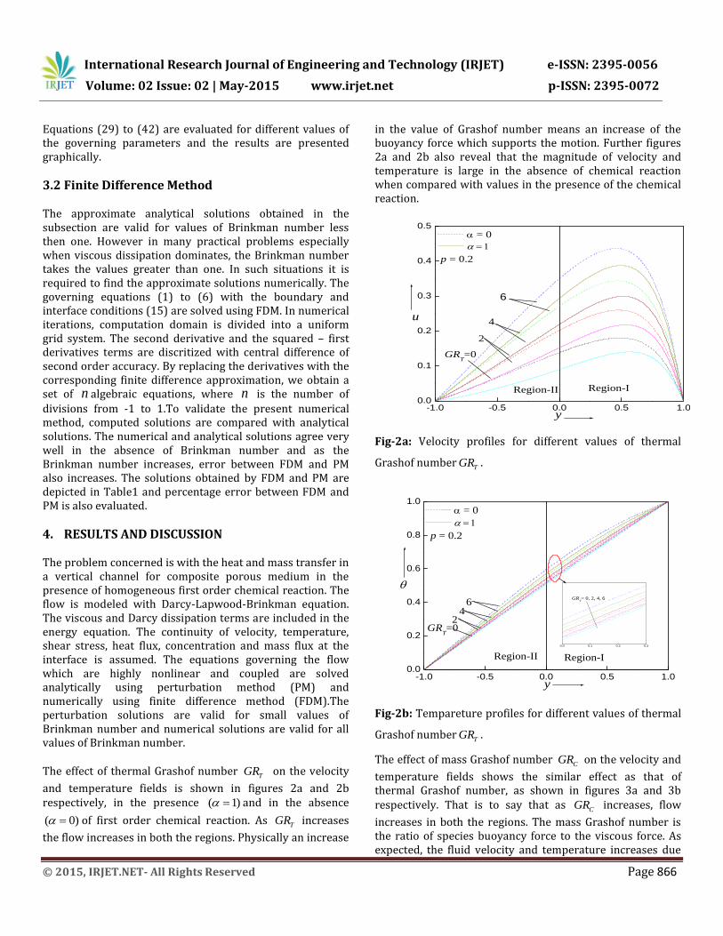
The problem concerned is with the heat and mass transfer in a vertical channel for composite porous medium in the presence of homogeneous first order chemical reaction. The flow is modeled with Darcy-Lapwood-Brinkman equation. The viscous and Darcy dissipation terms are included in the energy equation. The continuity of velocity, temperature, shear stress, heat flux, concentration and mass flux at the interface is assumed. The equations governing the flow which are highly nonlinear and coupled are solved analytically using perturbation method (PM) and numerically using finite difference method (FDM).The perturbation solutions are valid for small values of Brinkman number and numerical solutions are valid for all values of Brinkman number. The effect of thermal Grashof number TGR on the velocity
and temperature fields is shown in figures 2a and 2b respectively, in the presence ( 1) and in the absence
( 0) of first order chemical reaction. As TGR increases
the flow increases in both the regions. Physically an increase
in the value of Grashof number means an increase of the buoyancy force which supports the motion. Further figures 2a and 2b also reveal that the magnitude of velocity and temperature is large in the absence of chemical reaction when compared with values in the presence of the chemical reaction.
-1.0 -0.5 0.0 0.5 1.00.0
0.1
0.2
0.3
0.4
0.5
p = 0.2
= 0
y
u
2
GRT=0
4
6
Region-IRegion-II
Fig-2a: Velocity profiles for different values of thermal
Grashof number TGR .
-1.0 -0.5 0.0 0.5 1.00.0
0.2
0.4
0.6
0.8
1.0
0.0 0.1 0.2 0.3
= 0
p = 0.2
y
Region-IRegion-II
GRT=0
42
6GR
T= 0, 2, 4, 6
Fig-2b: Tempareture profiles for different values of thermal
Grashof number TGR .
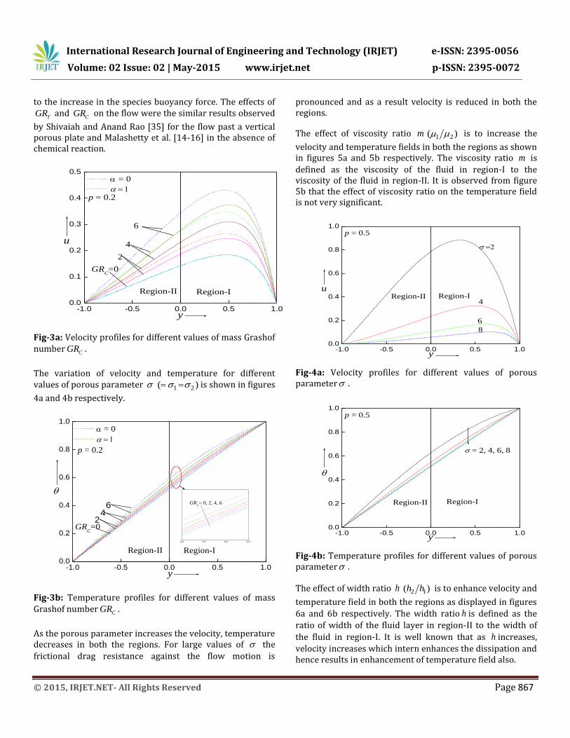
The effect of mass Grashof number CGR on the velocity and
temperature fields shows the similar effect as that of thermal Grashof number, as shown in figures 3a and 3b respectively. That is to say that as CGR increases, flow
increases in both the regions. The mass Grashof number is the ratio of species buoyancy force to the viscous force. As expected, the fluid velocity and temperature increases due
to the increase in the species buoyancy force. The effects of
TGR and CGR on the flow were the similar results observed
by Shivaiah and Anand Rao [35] for the flow past a vertical porous plate and Malashetty et al. [14-16] in the absence of chemical reaction.
-1.0 -0.5 0.0 0.5 1.00.0
0.1
0.2
0.3
0.4
0.5
p = 0.2
= 0
y
u
2
GRC=0
4
6
Region-IRegion-II
Fig-3a: Velocity profiles for different values of mass Grashof number
CGR .
The variation of velocity and temperature for different values of porous parameter 1 2( ) is shown in figures
4a and 4b respectively.
-1.0 -0.5 0.0 0.5 1.00.0
0.2
0.4
0.6
0.8
1.0
0.0 0.1 0.2 0.3
= 0
p = 0.2
y
Region-IRegion-II
GRC=0
42
6 GRC= 0, 2, 4, 6
Fig-3b: Temperature profiles for different values of mass Grashof number
CGR .
As the porous parameter increases the velocity, temperature decreases in both the regions. For large values of the
frictional drag resistance against the flow motion is
pronounced and as a result velocity is reduced in both the regions.
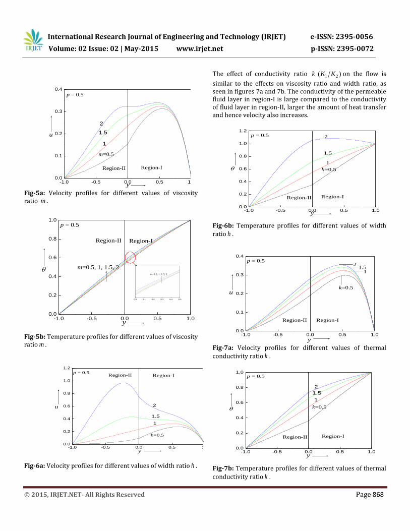
The effect of viscosity ratio m 1 2( ) is to increase the
velocity and temperature fields in both the regions as shown in figures 5a and 5b respectively. The viscosity ratio m is
defined as the viscosity of the fluid in region-I to the viscosity of the fluid in region-II. It is observed from figure 5b that the effect of viscosity ratio on the temperature field is not very significant.
-1.0 -0.5 0.0 0.5 1.00.0
0.2
0.4
0.6
0.8
1.0p = 0.5
Region-II Region-I
8
6
4
y
u
Fig-4a: Velocity profiles for different values of porous parameter .
-1.0 -0.5 0.0 0.5 1.00.0
0.2
0.4
0.6
0.8
1.0
p = 0.5
y
Region-II Region-I
= 2, 4, 6, 8
Fig-4b: Temperature profiles for different values of porous parameter .
The effect of width ratio h 2 1( )h h is to enhance velocity and
temperature field in both the regions as displayed in figures
6a and 6b respectively. The width ratio h is defined as the
ratio of width of the fluid layer in region-II to the width of
the fluid in region-I. It is well known that as h increases,
velocity increases which intern enhances the dissipation and hence results in enhancement of temperature field also.
Fig-5a: Velocity profiles for different values of viscosity ratio m .
-1.0 -0.5 0.0 0.5 1.00.0
0.2
0.4
0.6
0.8
1.0p = 0.5
0.0 0.1 0.2 0.3 0.4 0.5
m=0.5, 1, 1.5, 2
Region-II Region-I
m=0.5, 1, 1.5, 2
y
Fig-5b: Temperature profiles for different values of viscosity ratio m .
-1.0 -0.5 0.0 0.5 1.00.0
0.2
0.4
0.6
0.8
1.0
1.2
p = 0.5Region-IRegion-II
2
1
h=0.5
1.5
y
u
Fig-6a: Velocity profiles for different values of width ratio h .
The effect of conductivity ratio k 1 2( )K K on the flow is
similar to the effects on viscosity ratio and width ratio, as seen in figures 7a and 7b. The conductivity of the permeable fluid layer in region-I is large compared to the conductivity of fluid layer in region-II, larger the amount of heat transfer and hence velocity also increases.
-1.0 -0.5 0.0 0.5 1.00.0
0.2
0.4
0.6
0.8
1.0
1.2p = 0.5
Region-II Region-I
h=0.5
2
1
1.5
y
Fig-6b: Temperature profiles for different values of width
ratio h .
-1.0 -0.5 0.0 0.5 1.00.0
0.1
0.2
0.3
0.4p = 0.5
Region-II Region-I
2
11.5
k=0.5u
y
Fig-7a: Velocity profiles for different values of thermal
conductivity ratio k .
-1.0 -0.5 0.0 0.5 1.00.0
0.2
0.4
0.6
0.8
1.0p = 0.5
Region-II Region-I
2
1
1.5
k=0.5
y
Fig-7b: Temperature profiles for different values of thermal
The effects of h and k in the presence of first order chemical
reaction was the similar results observed by Malashetty [14] in the absence of first order chemical reaction.
-1.0 -0.5 0.0 0.5 1.00.0
0.1
0.2
0.3
0.4p = 0.5
2
1
1.5
=0.5
Region-II Region-I
u
y
Fig-8a: Velocity profiles for different values chemical reaction parameter .
-1.0 -0.5 0.0 0.5 1.00.0
0.2
0.4
0.6
0.8
1.0p = 0.5
0.0 0.1 0.2 0.3 0.4 0.5
0.5, 1, 1.5, 2
Region-II Region-I
=0.5, 1, 1.5, 2
y
Fig-8b: Temperature profiles for different values chemical reaction parameter .
-1.0 -0.5 0.0 0.5 1.00.0
0.2
0.4
0.6
0.8
1.0p = 0.5
Region-II Region-I
1.5
2
1
= 0.5
y
Fig-8c: Concentration profiles for different values chemical reaction parameter .
The effect of first order chemical reaction parameter on
velocity, temperature and concentration fields is depicted in figures 8a, 8b and 8c respectively. It is evident from these figures that as increases the velocity, temperature and
concentration are reduced in both the regions. Physically an increase in the values of increases in number of solute
molecules that undergoing chemical reaction resulting in decrease in the fluid flow. This was the similar results observed by Damesh and Shannak [36] for viscoelastic fluid and Krishnendu Bhattacharyya [37] for viscous fluid.
2 3 4 5 6 7 8
0.5
1.0
1.5
2.0
2.5
p = -5
m
h
k1
0.5
0.1
Qv
GRC
Fig-9: Effect of mass Grashof number, viscosity ratio, width ratio and conductivity ratio on the volume flow rate. Further, one can also come to the conclusion from figures 9,
10 and 11 that, as ,m h and k increases the total volumetric
flow rate, species concentration and heat rate also increases. The values of total volumetric flow rate, species concentration and heat rate remains the same when 1m h k .
2 3 4 5 6 7 8
0.2
0.4
0.6
0.8
1.0
1.2
p = -5
1
0.5
0.1
Cs
GRC
m
h
k
Fig-10: Effect of mass Grashof number, viscosity ratio, width ratio and conductivity ratio on total species rate added to the fluid.
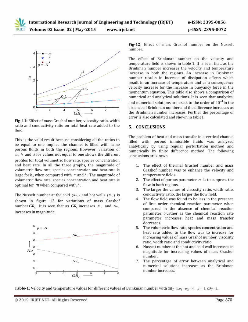
Fig-11: Effect of mass Grashof number, viscosity ratio, width ratio and conductivity ratio on total heat rate added to the fluid. This is the valid result because considering all the ratios to be equal to one implies the channel is filled with same porous fluids in both the regions. However, variation of
,m h and k for values not equal to one shows the different
profiles for total volumetric flow rate, species concentration and heat rate. In all the three graphs, the magnitude of volumetric flow rate, species concentration and heat rate is
large for k , when compared with m and h . The magnitude of
volumetric flow rate, species concentration and heat rate is
optimal for m when compared with h .
The Nusselt number at the cold ( )Nu and hot walls ( )Nu is
shown in figure 12 for variations of mass Grashof
number CGR . It is seen that as CGR increases Nu and Nu
increases in magnitude.
2 3 4 5 6 7 8
-6
-4
-2
0
2
4
6p = -5
Nu_
Nu+
GRC
Nu
Fig-12: Effect of mass Grashof number on the Nusselt number. The effect of Brinkman number on the velocity and temperature field is shown in table 1. It is seen that, as the Brinkman number increases the velocity and temperature increase in both the regions. An increase in Brinkman number results in increase of dissipation effects which result in an increase of temperature and as a consequence velocity increase for the increase in buoyancy force in the momentum equation. This table also shows a comparison of numerical and analytical solutions. It is seen that analytical
and numerical solutions are exact to the order of 410 in the
absence of Brinkman number and the difference increases as the Brinkman number increases. Further the percentage of error is also calculated and shown in table1.
5. CONCLUSIONS The problem of heat and mass transfer in a vertical channel filled with porous immiscible fluids was analyzed analytically by using regular perturbation method and numerically by finite difference method. The following conclusions are drawn
1. The effect of thermal Grashof number and mass Grashof number was to enhance the velocity and temperature fields.
2. The effect of porous parameter is to suppress the
flow in both regions. 3. The larger the values of viscosity ratio, width ratio,
conductivity ratio, the larger the flow field. 4. The flow field was found to be less in the presence
of first order chemical reaction parameter when compared in the absence of chemical reaction parameter. Further as the chemical reaction rate parameter increases heat and mass transfer decreases.
5. The volumetric flow rate, species concentration and heat rate added to the flow was to increase for increasing values of mass Grashof number, viscosity ratio, width ratio and conductivity ratio.
6. Nusselt number at the hot and cold wall increases in magnitude for increasing values of mass Grashof number.
7. The percentage of error between analytical and numerical solutions increases as the Brinkman number increases.
Table-1: Velocity and temperature values for different values of Brinkman number with 1 2=1, = = 4CGR , = -1, =1Tp GR .
ACKNOWLEDGMENT One of the author Dr. J. Prathap Kumar would like to thank University Grants Commission – New Delhi for the financial support under UGC- Major Research project (Project No. 41-774/2012 (SR)).
REFERENCES
[1] D. A. Nield, A. Bejan, Convection in Porous Media. New
York, Springer-Verlag, 2006.
[2] M. Kaviany, Principles of heat transfer in porous media.
Springer-Verlag New York, 1991.
[3] K. Vafai, C. L. Tien, Boundary and inertia effects on flow
and heat transfer in porous media, Int. J. Heat Mass
Transfer, vol. 24, pp. 195-203, 1981.
[4] M. Kaviany, Laminar flow through a porous channel
bounded by isothermal parallel plates, International
Journal of Heat Mass Transfer, vol. 28, pp. 851-858,
1985.
[5] N. Rudriah, S. T. Nagraj, Natural convection through
vertical porous stratum, Int. J. Eng. Sci., vol. 15, pp.
589- 600 , 1977.
[6] C. Beckermann, R. Viskanta, S. Ramadhyani, Natural
convection in vertical enclosures containing
simultaneously fluid and porous layers, The Journal of
Fluid Mechanics, vol. 186, pp. 257-284, 1988.
[7] A. K. Singh, T. Paul, G. R. Thorpe, Natural convection due
to heat and mass transfer in a Composite system, Heat
and Mass Transfer, vol. 35, pp. 39-48, 1999.
[8] D. Poulikkos, M. Kazmierczak, Forced convection in a
duct partially filled with a porous material, ASME J.
Heat Transfer, vol. 109, pp. 653-662, 1987.
[9] A.V. Kuznetsov, Analytical study of fluid flow and heat
transfer during forced convection in a composite
channel partly filled with a Brinkman-Forchheimer
porous medium, Flow Turbulence Combust, vol. 60, pp.
173-192, 1998.
[10] V. Prasad, Convective flow interaction and heat transfer
between fluid and porous layers.In: Proceeding of NATO
advanced Study Institute on Convective Heat and Mass
Transfer in Porous Medium, Izmir, Turkey, 1990.
[11] B. Alzami, K. Vafai, Analysis of fluid flow and Heat
transfer interfacial conditions between a porous
medium and fluid layer, Int. J. Heat Mass Transfer, vol.
44, pp. 1735-1749, 2001.
[12] J. W. Paek, B. H. Kang, S. Y. Kim, J. M. Hyan, Effective
thermal conductivity and permeability of aluminum
foam materials, Int. J. Thermophys, vol. 21, pp. 453-464,
[13] D. A. Nield, A. V. Kuznetsov, Effect of heterogeneity in
forced convection in porous medium: Parallel plate
channel or circular duct, Int. J. Heat Mass Transfer, vol.
43, pp. 4119- 4134, 2000.
[14] M. S. Malashetty, J. C. Umavthi, J. Prathap Kumar,
Convective flow and heat transfer in a composite
porous medium, J. Porous Media, vol. 4, pp. 15-22, 2001.
[15] M. S. Malashetty, J. C. Umavthi, J. Prathap Kumar, Two
fluid flow heat transfer in an inclined channel containing
porous and fluid layer, Heat Mass Transfer, vol. 40, pp.
871-876, 2004.
[16] M. S. Malashetty, J. C. Umavthi, J. Prathap Kumar, Flow
and heat transfer in an inclined channel containing a
fluid layer sandwiched between two porous layers, J.
Porous Media, vol. 8, pp. 443-453, 2005.
[17] J. C. Umavthi, J. Prathap Kumar, A. J. Chamaka, I. Pop,
Mixed convection in a vertical porous channel, Transp.
Porous Media, vol. 61, pp. 315-335, 2005.
[18] J. C. Umavthi, A. J. Chamaka, Abdul Mateen, A. AlMudhaf,
Oscillatory flow and heat transfer in a horizontal
vertical channel with asymmetric wall heating
conditions, Journal of porous media, vol. 33, pp. 271-285,
2010.
[19] J. C. Umavthi, A. J. Chamaka, Abdul Mateen, A.
AlMudhaf, Unsteady oscillatory flow and heat transfer
in a horizontal composite porous medium channel,
Nonlinear Analysis: Modeling and Control, vol. 14, pp.
397–415, 2009.
[20] J. C. Umavthi, J. Prathap Kumar, K. S. R. Sridhar, Flow and heat transfer of Poiseuille- Couette flow in a inclined channel for composite porous medium, Int. J. Applied Mechanics and Enginring, vol. 15, pp. 249-266, 2010.
[21] J. C. Umavathi, J. Ali. Chamkha, K. S. R. Sridhar, Generalized plain couette flow and heat transfer in a composite channel, Transp. Porous Media, vol. 85, pp. 157–169, 2010a.
[22] J. C. Umavathi, I. C. Liu, J. Prathap Kumar, D. Shaik-
Meera, Unsteady flow and heat transfer of porous
media sandwiched between viscous fluids, Appl. Math.
Mec. - Engl. Ed. vol. 31, pp. 1497–1516, 2010b.
[23] J. C. Umavathi, I.C. Liuand, H. H. Wang, Poiselle-Couette
flow and heat transfer an inclined channel for composite
porous medium, Journal of Mechanics, vol. 48, pp. 2221–
2232, 2012.
[24] J. C. Umavathi, M. H. Manjula, Convective two fluid flows
through a vertical channel, AMSE Modeling Measurement
and Control, vol. 75, pp. 1-18, 2006.
[25] J.C. Umavathi, Free convection of composite porous
medium in a vertical channel, Heat Transfer-Asian
Research, vol. 40, pp. 308-329, 2011.
[26] J. Prathap Kumar, J.C. Umavathi, I. Pop, M. Basavaraj
Biradar, Fully developed mixed convection flow in a
vertical channel containing porous and fluid layer with
isothermal or isoflux boundaries, Transp. Porous Med.,
vol. 80, pp. 117–135, 2009.
[27] J. Prathap Kumar, J.C. Umavathi, I. Pop, M. Basavaraj
Biradar, Mixed convection of a composite porous
medium in a composite porous medium channel, Int. J.
Heat and Tech., vol. 25, pp.75-86, 2006.
[28] A. J. Chamkha, MHD flow of a uniformly stretched
vertical permeable surface in the presence of heat
generation/absorption and chemical reaction, Int.
Comm. Heat Mass Transfer, vol. 30, pp. 413-422, 2003.
[29] R. Muthucumaraswamy, P. Ganeshan, Natural
convection on a moving isothermal vertical plate with
chemical reaction, Eng. Phys. Thermophys, vol. 75, pp.
113-119, 2002.
[30] P. Singh, K. Queeny, Free convection heat and mass
transfer along a vertical surface in a porous medium,
Acta Mech., vol. 123, pp. 69-73, 1997.
[31] A. Postelincu, Influence of chemical reaction on heat
and mass transfer by natural convection from vertical
surfaces in porous media, Heat and Mass Transfer, vol.
43, pp. 595-602, 2007.
[32] J. Prathap Kumar, J.C. Umavathi, Shivakumar
Madhavarao, Dispersion in composite porous medium
with homogeneous and heterogeneous chemical
reactions, Heat Transfer-Asian Research, vol. 40, pp. 608-
640, 2011.
[33] J. Prathap Kumar, J.C. Umavathi, Shivakumar
Madhavarao, Effect of homogeneous and heterogeneous
reactions on the solute dispersion in composite porous
medium, Int. J. Eng. Sci. and Tech., vol. 4, pp. 58-76,
2012a.
[34] J. Prathap Kumar, J.C. Umavathi, M. Basavaraj Biradar,
Effects of homogeneous and heterogeneous reactions on
the dispersion of a solute for immiscible viscous fluids
between two plates, Journal of Applied Fluid Mechanics,
[35] S. Shivaiah, J. Anad Rao, Chemical reaction effects on an un steady MHD free convection flow past a vertical porous plate in the presence of suction or injection, App Mech., vol. 39, pp. 185-208, 2012.
[36] R. A. Damesh, B. A. Shannak, Viscoelastic fluid flow past an infinite vertical porous plate in the presence of
first order chemical reaction, Applied Mathematics and Mechanics, vol. 31, pp. 955-962, 2010.
[37] Krishnendu Bhattacharyya, Slip effects on boundary
layer flow and mass transfer with chemical reaction
over a permeable flat plate in a porous medium,
Frontiers in Heat and Mass Transfer (FHMT) 3, 043006,


![FLOW DYNAMICS OF COMPLEX FLUIDS USING NUMERICAL …€¦ · flow (immiscible fluids separated by identifiable interfaces) [2]. There are also non-dispersed multiphase flows such as](https://static.documents.pub/doc/80x56/5f358903914ad922bc4071ba/flow-dynamics-of-complex-fluids-using-numerical-flow-immiscible-fluids-separated.jpg)


