HAL Id: hal-01351492 https://hal.archives-ouvertes.fr/hal-01351492 Submitted on 4 Aug 2016 HAL is a multi-disciplinary open access archive for the deposit and dissemination of sci- entific research documents, whether they are pub- lished or not. The documents may come from teaching and research institutions in France or abroad, or from public or private research centers. L’archive ouverte pluridisciplinaire HAL, est destinée au dépôt et à la diffusion de documents scientifiques de niveau recherche, publiés ou non, émanant des établissements d’enseignement et de recherche français ou étrangers, des laboratoires publics ou privés. Mixed-integer linear programming for multibeam satellite systems design: Application to the beam layout optimization Jean-Thomas Camino, Christian Artigues, Laurent Houssin, Stéphane Mourgues To cite this version: Jean-Thomas Camino, Christian Artigues, Laurent Houssin, Stéphane Mourgues. Mixed-integer linear programming for multibeam satellite systems design: Application to the beam layout optimization. 2016 Annual IEEE Systems Conference (SysCon), Apr 2016, Orlando, FL, United States. pp.1-6, 10.1109/SYSCON.2016.7490613. hal-01351492
Transcript
HAL Id: hal-01351492https://hal.archives-ouvertes.fr/hal-01351492
Submitted on 4 Aug 2016
HAL is a multi-disciplinary open accessarchive for the deposit and dissemination of sci-entific research documents, whether they are pub-lished or not. The documents may come fromteaching and research institutions in France orabroad, or from public or private research centers.
L’archive ouverte pluridisciplinaire HAL, estdestinée au dépôt et à la diffusion de documentsscientifiques de niveau recherche, publiés ou non,émanant des établissements d’enseignement et derecherche français ou étrangers, des laboratoirespublics ou privés.
Mixed-integer linear programming for multibeamsatellite systems design: Application to the beam layout
optimizationJean-Thomas Camino, Christian Artigues, Laurent Houssin, Stéphane
Mourgues
To cite this version:Jean-Thomas Camino, Christian Artigues, Laurent Houssin, Stéphane Mourgues. Mixed-integer linearprogramming for multibeam satellite systems design: Application to the beam layout optimization.2016 Annual IEEE Systems Conference (SysCon), Apr 2016, Orlando, FL, United States. pp.1-6,�10.1109/SYSCON.2016.7490613�. �hal-01351492�
Mixed-Integer Linear Programming for MultibeamSatellite Systems Design: Application to the Beam
Layout OptimizationJean-Thomas Camino(1)(2), Christian Artigues(2), Laurent Houssin(2), Stephane Mourgues(1)
(1)Airbus Defence and Space, Space Systems, Telecommunication Systems Department,31 Rue des Cosmonautes, 31402 Toulouse, France
(2)LAAS-CNRS, Universite de Toulouse, CNRS, UPS, Toulouse, France
Abstract— In a society where the demand for multimediaapplications and data exchange is experiencing an unstoppablegrowth, multibeam systems have proven to be one of the mostrelevant solutions for satellite-based communication systems.Though already well represented among the geostationary satel-lites today, there are still several unresolved design optimizationchallenges for these complex systems that could lead to improvedperformances and to better system costs. The satellite platform,the repeater, and the antennas are examples of subsystems thatshould be designed jointly in order to reach an optimized tech-nical solution that fulfills the service requirements. Traditionally,such complex tasks are addressed through a decomposition of theoverall system design into a sequence of smaller decision prob-lems. In this article, we propose to rely on operations researchtechniques to, on the one hand, take into account explicitly the in-terdependencies of these decomposed problems, and on the otherhand, to handle the own constraints of each subsystem and theirinteractions. In this paper, the focus is laid on the optimization ofthe beam layouts of the multibeam satellites. Indeed, in additionto being a perfect example of the aforementioned importance ofdealing with subsystem constraints, this problem appears earlyin the chain of design of a multibeam satellite system and istherefore critical for the quality of the telecommunication system:the weaknesses of a beam layout cannot be made up for lateron in the system design. For this crucial optimization phase,the strength of the methodology we propose in this paper is touse mixed-integer linear programming to incorporate explicitlytechnological feasibility constraints of the subsystems involved,while preparing at best the subsequent design problems. Mostimportantly, our approach allows to overcome several resistingflaws of the already existing algorithms.
Keywords: Satellite Telecommunications, Systems Design,Mixed-Integer Linear Programming, Operations Research
I. INTRODUCTION
On the service area of a given satellite system, any user can bereached regardless of its location. This is particularly interestingfor rural areas for which deploying a terrestrial network is hard oreven impossible. This unique characteristic of the satellite systemscombined with their ability to offer all kinds of telecommunicationservices (television, radio, telephone, internet...) have made themindispensable in our ultra-connected society. A multibeam satelliteis a particular type of telecommunication satellite characterized bya plurality of relatively narrow beams used to provide coverage toits service area. As discussed further in the article, compared tosystems that use only one large beam to cover the entire service area,
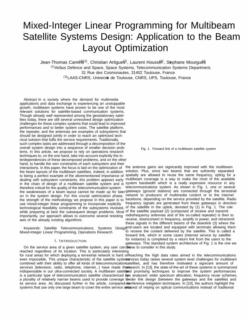
Fig. 1. Forward link of a multibeam satellite system
the antenna gains are significantly improved with the multibeamsolution. Plus, since two beams that are sufficiently separatedspatially are allowed to reuse the same frequency, opting for amultibeam coverage is a way to make the most of the availablesystem bandwidth which is a really expensive resource in anytelecommunications system. As shown in Fig. 1, one or severalgateways (ground stations) are connected through the terrestrialnetwork to producers of multimedia content or to the internetbackbone, depending on the service provided by the satellite. Radiofrequency signals are generated from these gateways in directionof the satellite in the uplink, denoted by (1) in Fig. 1. The roleof the satellite payload (2) (composed of “receive” and “transmit”radiofrequency antennas and of the so-called “repeater”) is then toreceive, downconvert in frequency, amplify in power, and retransmitthese signals in the different beams of the downlink (3) where theend-users are located and equipped with terminals allowing themto receive the content delivered by the satellite. This is called a“forward link”, which in some cases (internet service by satellitefor instance) is completed by a “return link” from the users to thegateways. This standard system architecture of Fig. 1 is the one wechose to consider in this study.
Reaching the high data rates aimed in the telecommunicationsservices today raises several system level challenges for multibeamsatellites, and has therefore motivated a significant amount ofresearch. In [13], the state-of-the-art of these systems is summarizedand promising techniques to improve the system performancesare analyzed: wider spectrum allocation, frequency reuse schemes,feeder link design (between the gateways and the satellite) andinterference mitigation techniques. In [10], the authors highlight theinterest of relying on optical communications instead of traditional
radiofrequency signals for the feeder link of geostationary satellitesystems, and propose a methodology and algorithms to tackle theseveral design issues that these innovative system architecturesraise. The authors of [5] analyse multibeam systems that use twoco-localized multibeam satellites that are coordinated to provideenhanced and more robust performances. Some research papersfocus exclusively on one of the satellite subsystems: for instance,the authors of [12] investigate algorithms to optimize the design ofmultibeam array antennas. For a given system architecture and agiven satellite payload, literature is also rich on the question of howto optimize the allocation of resources such as the satellite power andthe system bandwidth: [9], [6], [7], [14] and [11] for instance. On theother hand, the stress is rarely put on the strong interdependenciesof all the subsystems of a multibeam satellite system in the designphase. Under the assumption that the system architecture has alreadybeen chosen and is the one of Fig. 1, the objective of this articleis indeed to demonstrate that, when some crucial design problemsare not solved jointly for the different subsystems involved, then,whatever the quality of the following allocation of resources andindividual subsystem optimization processes, the overall systemsolution will be either technologically infeasible or perfectible interms of cost or performances. We also show that in the case ofthe complex systems that are the multibeam satellite networks, theprocess of making optimized technical decisions can be greatlyenhanced if one relies on operations research techniques to handlethe numerous constraints and criteria of all the different subsystemsthat interact. In this context, the beam layout optimization problemis presented and an example of algorithmic solution is provided andcompared to the literature on the subject.
The rest of the article is structured as follows. Section IIdefines precisely the telecommunication mission requirementsthat are at the start of any multibeam system. They are derivedinto a set of design challenges, the stress being put on the spacesegment optimization for which a design process is proposed. Insection III, the crucial beam layout optimization step is tackled withoperations research techniques and more particularly mixed-integerlinear programming: the assumptions made and the mathematicalmodels are detailed. Section IV presents experimental results andcomparisons with other algorithmic solutions. The conclusion andthe way forward are discussed in section V.
II. TELECOMMUNICATION MISSIONS ANDCORRESPONDING DESIGN CHALLENGES
The requirements of the telecommunication missions can be ofdifferent types. In their most general form, they consist of a series ofspecific services that should be provided to designated regions of theEarth: television, radio, telephone, broadband applications (internet,videoconferencing...) to name a few. Both the quality and the quantityof these services can be specified. In addition, there might be forinstance cost constraints on the overall system. Here, we will considerrequirements inspired by broadband applications, where each pointdefined on the service area has its own traffic request expressedin Megabits per second, as illustrated with the fictitious scenarioof Fig. 2 (generated randomly). From this specification of needs,the satellite system manufacturers must propose a whole solutionincluding details on the ground segment (the gateways and the controlcenters), the user segment (satellite terminals), and the space segment(one multibeam satellite in the case considered here). Each of thesethree complex systems can be split in several subsystems with theirown particularities and design challenges. It is impossible today,either numerically or manually by experienced engineers, to designglobally the three segments of a multibeam satellite system: there aretoo many decisions to make on numerous interacting subsystems, andcomputationally heavy system simulations to assess the performancesof the selected designs. The standard way to deal with such an issue
Fig. 2. Example of traffic demand map
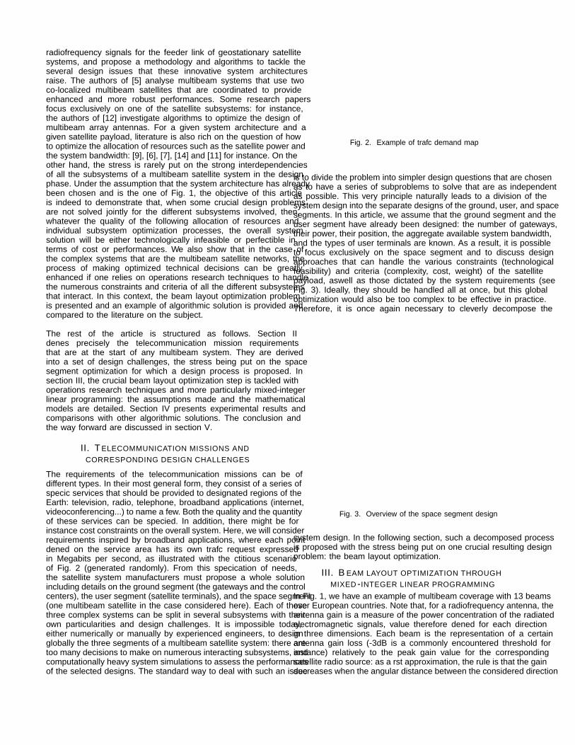
is to divide the problem into simpler design questions that are chosenas to have a series of subproblems to solve that are as independentas possible. This very principle naturally leads to a division of thesystem design into the separate designs of the ground, user, and spacesegments. In this article, we assume that the ground segment and theuser segment have already been designed: the number of gateways,their power, their position, the aggregate available system bandwidth,and the types of user terminals are known. As a result, it is possibleto focus exclusively on the space segment and to discuss designapproaches that can handle the various constraints (technologicalfeasibility) and criteria (complexity, cost, weight) of the satellitepayload, aswell as those dictated by the system requirements (seeFig. 3). Ideally, they should be handled all at once, but this globaloptimization would also be too complex to be effective in practice.Therefore, it is once again necessary to cleverly decompose the
Fig. 3. Overview of the space segment design
system design. In the following section, such a decomposed processis proposed with the stress being put on one crucial resulting designproblem: the beam layout optimization.
III. BEAM LAYOUT OPTIMIZATION THROUGHMIXED-INTEGER LINEAR PROGRAMMING
In Fig. 1, we have an example of multibeam coverage with 13 beamsover European countries. Note that, for a radiofrequency antenna, theantenna gain is a measure of the power concentration of the radiatedelectromagnetic signals, value therefore defined for each directionin three dimensions. Each beam is the representation of a certainantenna gain loss (-3dB is a commonly encountered threshold forinstance) relatively to the peak gain value for the correspondingsatellite radio source: as a first approximation, the rule is that the gaindecreases when the angular distance between the considered direction
and the peak direction increases. Also note that the bigger the beam,the less the peak antenna gain for this beam, which explains whymultibeam systems are attractive compared to single beam systemsthat cover the same regions with only one large beam. From the pointof view of the satellite, and looking in direction of the Earth, commonsatellite antenna designs lead to beams that can be represented bydisks on the surface of the Earth. This results in the definition ofthe “beamwidth” which is simply the diameter of such disks. Wewill say that a station is covered by a beam if its disk representationcontains this station. For a given service area, defining a beam layoutmeans deciding what will be the number of beams, the position ofthe beam centers on the surface of the Earth, the beam diameters,the mapping of the user stations to the different beams, and thesatellite reflector antenna associated to each beam. Note that theperformances and cost of a broadband satellite system are expectedto differ notably from one beam layout to another according to howthe heterogeneity of the traffic demand (case considered) over theregions to cover is handled. One key remark is that the commonbeam layout solutions are not well suited for heterogeneous trafficdemands (see III-B). On the other hand, potentially more appropriatesolutions can cause a significant increase on the payload complexityor can compromise the technological feasibility, which needs to becontrolled from the start when the beam layout is defined. This is whywe decided to devote particular attention to this already very complexoptimization: the beam layout is the first step of the space segmentdesign we propose in Fig. 4. As discussed earlier, the only way thisprocess can be effective is by making explicit the links between thedifferent design steps. To that end, we chose to propose an algorithmicsolution that defines the beam layout under antenna and repeaterconstraints to create favorable conditions for the subsequent designoptimization phases: antenna and repeater design. Of course, therequired system performances and cost are already targeted duringthis first optimization. These constraints and objectives are detailedin the following section.
A. Considered constraints and objectives
1) Platform constraints :The main platform constraint we will consider is the limit on thenumber of beams that can be embarked on the spacecraft. This canbe due to either power, cost, mass or accommodation limitations.In any case, we will explicitly integrate this upper-bound on thenumber of beams in our beam layout optimization algorithm.
2) Antenna constraints :As illustrated in Fig. 1, each beam is transmitted by exactly
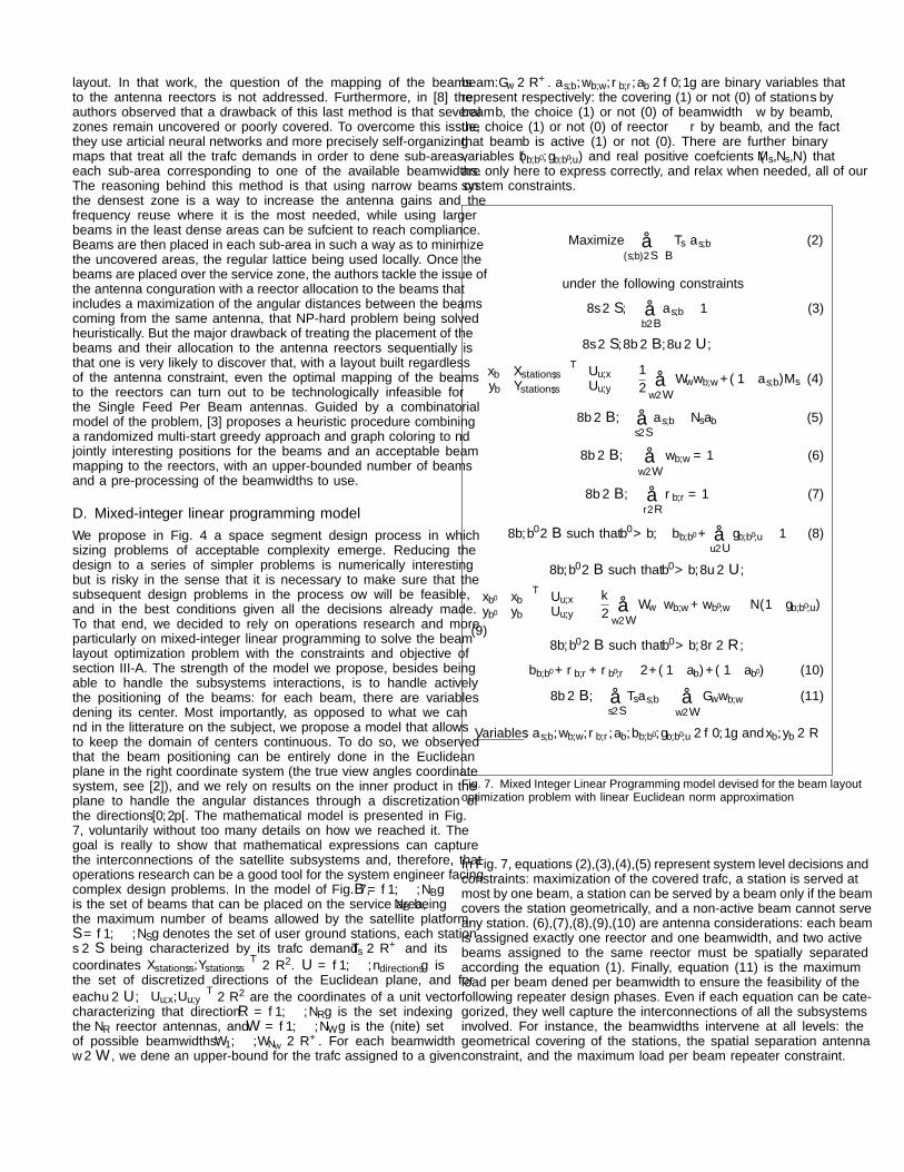
one satellite reflector antenna (4 of them are represented, eachone characterized by its own color). Under the assumption adoptedthroughout this study that Single Feed Per Beam antennas are used(one radio source per beam), the main technological constraint isthat, for each layout considered, there must exist a mapping ofthe beams to the different reflector antennas for which there isno overlapping in the corresponding blocks of sources. This leadsto a minimum angular distance from the satellite point of viewbetween two beams associated to the same reflector antenna, thatdistance being a function of the size of the sources. This technologicalconstraint is represented in Fig. 5 where some elements of the antennageometry are represented: the focus O, the focal length F , the slantfocal length Fs, the diameter D (projection of the parabola diameteron the focal plane), and the angular distance between the beams ∆θ
caused by the inter-source distance ∆i, j. The important property isthat using larger beamwidths requires larger sources to concentratethe illumination on a reduced reflector surface, which leads to greaterminimum inter-sources distances and, therefore, to greater minimumseparation distances. In practice, the rule we decided to use for theremainder of the study was to assume that the minimum angularseparation for two beams transmitted by the same reflector is directly
proportional to the mean of their two beamwidths, according to acoefficient κ ∈ R+ such that
32≤ κ ≤
√3 (1)
This range is representative of commonly encountered configurationsfor such Single Feed Per Beam satellite systems.
3) Repeater limitations constraints :Note that the traffic demanding stations are assigned to the beamsleading to an aggregate traffic request per beam. While thesedemands are a result of the beam layout optimization procedure,they are strongly connected to the following payload design phases.For instance, we can define for each beam a maximum trafficdemand (that would depend on the beam diameter) above whichwe lose the guarantee that there will exist a feasible repeaterarchitecture (hardware, frequency plan and bandwidth allocation)that can answer properly to that demand. This is exactly theconstraint we implemented to make sure that the following payloaddesign challenges can be resolved.
4) Objective :Each station is characterized by its own traffic demand. The objectivewe decide to target is the maximization of the aggregate coveredtraffic, the ideal goal being 100%. Note that the traffic of a givenstation is considered covered when this station is covered by at leastone beam and assigned to one of them.
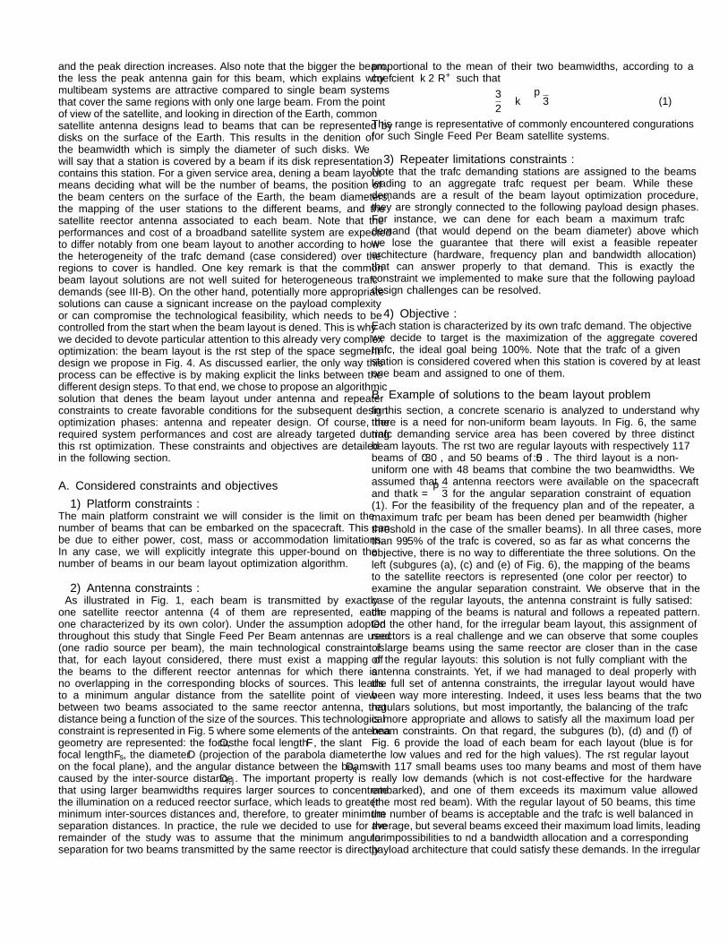
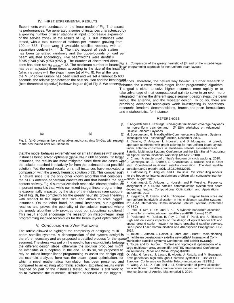
B. Example of solutions to the beam layout problemIn this section, a concrete scenario is analyzed to understand whythere is a need for non-uniform beam layouts. In Fig. 6, the sametraffic demanding service area has been covered by three distinctbeam layouts. The first two are regular layouts with respectively 117beams of 0.30◦, and 50 beams of 0.5◦. The third layout is a non-uniform one with 48 beams that combine the two beamwidths. Weassumed that 4 antenna reflectors were available on the spacecraftand that κ =
√3 for the angular separation constraint of equation
(1). For the feasibility of the frequency plan and of the repeater, amaximum traffic per beam has been defined per beamwidth (higherthreshold in the case of the smaller beams). In all three cases, morethan 99.5% of the traffic is covered, so as far as what concerns theobjective, there is no way to differentiate the three solutions. On theleft (subfigures (a), (c) and (e) of Fig. 6), the mapping of the beamsto the satellite reflectors is represented (one color per reflector) toexamine the angular separation constraint. We observe that in thecase of the regular layouts, the antenna constraint is fully satisfied:the mapping of the beams is natural and follows a repeated pattern.On the other hand, for the irregular beam layout, this assignment ofreflectors is a real challenge and we can observe that some couplesof large beams using the same reflector are closer than in the caseof the regular layouts: this solution is not fully compliant with theantenna constraints. Yet, if we had managed to deal properly withthe full set of antenna constraints, the irregular layout would havebeen way more interesting. Indeed, it uses less beams that the tworegulars solutions, but most importantly, the balancing of the trafficis more appropriate and allows to satisfy all the maximum load perbeam constraints. On that regard, the subfigures (b), (d) and (f) ofFig. 6 provide the load of each beam for each layout (blue is forthe low values and red for the high values). The first regular layoutwith 117 small beams uses too many beams and most of them havereally low demands (which is not cost-effective for the hardwareembarked), and one of them exceeds its maximum value allowed(the most red beam). With the regular layout of 50 beams, this timethe number of beams is acceptable and the traffic is well balanced inaverage, but several beams exceed their maximum load limits, leadingto impossibilities to find a bandwidth allocation and a correspondingpayload architecture that could satisfy these demands. In the irregular
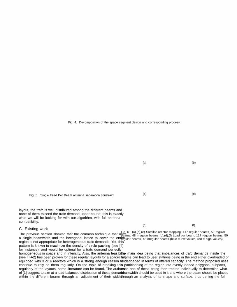
Fig. 4. Decomposition of the space segment design and corresponding process
×
b
S
Fs
0
D
F
~n
∆1,2
b
b
∆θ
Fig. 5. Single Feed Per Beam antenna separation constraint
layout, the traffic is well distributed among the different beams andnone of them exceed the traffic demand upper-bound: this is exactlywhat we will be looking for with our algorithm, with full antennacompatibility.
C. Existing workThe previous section showed that the common technique that usesa single beamwidth and the hexagonal lattice to cover the entireregion is not appropriate for heterogeneous traffic demands. Yet, thispattern is known to maximize the density of circle packing (see [4]for instance), and would be optimal for a traffic demand perfectlyhomogeneous in space and in intensity. Also, the antenna feasibility(see III-A2) has been proven for these regular layouts for a spacecraftequipped with 3 or 4 reflectors which is a strong enough reason tocontinue to rely on them regularly. On the topic of breaking thisregularity of the layouts, some litterature can be found. The authorsof [1] suggest to aim at a load-balanced distribution of these demandswithin the different beams through an adjustment of their widths,
the main idea being that imbalances of traffic demands inside thebeams can lead to user stations being in the end either overloaded orunderloaded in terms of offered capacity. The method proposed usesa partitionning of the region into evenly loaded polygonal subparts,each one of these being then treated individually to determine whatbeamwidth should be used in it and where the beam should be placedthrough an analysis of its shape and surface, thus defining the full
layout. In that work, the question of the mapping of the beamsto the antenna reflectors is not addressed. Furthermore, in [8] theauthors observed that a drawback of this last method is that severalzones remain uncovered or poorly covered. To overcome this issue,they use artificial neural networks and more precisely self-organizingmaps that treat all the traffic demands in order to define sub-areas,each sub-area corresponding to one of the available beamwidths.The reasoning behind this method is that using narrow beams onthe densest zone is a way to increase the antenna gains and thefrequency reuse where it is the most needed, while using largerbeams in the least dense areas can be sufficient to reach compliance.Beams are then placed in each sub-area in such a way as to minimizethe uncovered areas, the regular lattice being used locally. Once thebeams are placed over the service zone, the authors tackle the issue ofthe antenna configuration with a reflector allocation to the beams thatincludes a maximization of the angular distances between the beamscoming from the same antenna, that NP-hard problem being solvedheuristically. But the major drawback of treating the placement of thebeams and their allocation to the antenna reflectors sequentially isthat one is very likely to discover that, with a layout built regardlessof the antenna constraint, even the optimal mapping of the beamsto the reflectors can turn out to be technologically infeasible forthe Single Feed Per Beam antennas. Guided by a combinatorialmodel of the problem, [3] proposes a heuristic procedure combininga randomized multi-start greedy approach and graph coloring to findjointly interesting positions for the beams and an acceptable beammapping to the reflectors, with an upper-bounded number of beamsand a pre-processing of the beamwidths to use.
D. Mixed-integer linear programming modelWe propose in Fig. 4 a space segment design process in whichsizing problems of acceptable complexity emerge. Reducing thedesign to a series of simpler problems is numerically interestingbut is risky in the sense that it is necessary to make sure that thesubsequent design problems in the process flow will be feasible,and in the best conditions given all the decisions already made.To that end, we decided to rely on operations research and moreparticularly on mixed-integer linear programming to solve the beamlayout optimization problem with the constraints and objective ofsection III-A. The strength of the model we propose, besides beingable to handle the subsystems interactions, is to handle activelythe positioning of the beams: for each beam, there are variablesdefining its center. Most importantly, as opposed to what we canfind in the litterature on the subject, we propose a model that allowsto keep the domain of centers continuous. To do so, we observedthat the beam positioning can be entirely done in the Euclideanplane in the right coordinate system (the true view angles coordinatesystem, see [2]), and we rely on results on the inner product in theplane to handle the angular distances through a discretization ofthe directions [0,2π[. The mathematical model is presented in Fig.7, voluntarily without too many details on how we reached it. Thegoal is really to show that mathematical expressions can capturethe interconnections of the satellite subsystems and, therefore, thatoperations research can be a good tool for the system engineer facingcomplex design problems. In the model of Fig. 7, B = {1, · · · ,NB}is the set of beams that can be placed on the service area, NB beingthe maximum number of beams allowed by the satellite platform.S = {1, · · · ,NS} denotes the set of user ground stations, each stations ∈ S being characterized by its traffic demand Ts ∈ R+ and itscoordinates
(Xstations,s,Ystations,s
)T ∈ R2. U = {1, · · · ,ndirections} isthe set of discretized directions of the Euclidean plane, and foreach u ∈ U,
(Uu,x,Uu,y
)T ∈ R2 are the coordinates of a unit vectorcharacterizing that direction. R = {1, · · · ,NR} is the set indexingthe NR reflector antennas, and W = {1, · · · ,NW } is the (finite) setof possible beamwidths: W1, · · · ,WNW ∈ R+. For each beamwidthw ∈ W , we define an upper-bound for the traffic assigned to a given
beam: Γw ∈ R+. αs,b,ωb,w,ρb,r,ab ∈ {0,1} are binary variables thatrepresent respectively: the covering (“1”) or not (“0”) of station s bybeam b, the choice (“1”) or not (“0”) of beamwidth w by beam b,the choice (“1”) or not (“0”) of reflector r by beam b, and the factthat beam b is active (“1”) or not (“0”). There are further binaryvariables (βb,b′ ,γb,b′,u) and real positive coefficients (Ms,Ns,N) thatare only here to express correctly, and relax when needed, all of oursystem constraints.
Maximize ∑(s,b)∈S×B
Ts αs,b (2)
under the following constraints
∀s ∈ S , ∑b∈B
αs,b ≤ 1 (3)
∀s ∈ S ,∀b ∈ B,∀u ∈ U,(xb −Xstations,syb −Ystations,s
)T (Uu,xUu,y
)≤ 1
2 ∑w∈W
Wwωb,w +(1−αs,b)Ms (4)
∀b ∈ B, ∑s∈S
αs,b ≤ Nsab (5)
∀b ∈ B, ∑w∈W
ωb,w = 1 (6)
∀b ∈ B, ∑r∈R
ρb,r = 1 (7)
∀b,b′ ∈ B such that b′ > b, βb,b′ + ∑u∈U
γb,b′,u ≥ 1 (8)
∀b,b′ ∈ B such that b′ > b,∀u ∈ U,(xb′ − xbyb′ − yb
)T (Uu,xUu,y
)≥ κ
2 ∑w∈W
Ww(ωb,w +ωb′,w
)−N(1− γb,b′,u)
(9)∀b,b′ ∈ B such that b′ > b,∀r ∈ R ,
βb,b′ +ρb,r +ρb′,r ≤ 2+(1−ab)+(1−ab′) (10)
∀b ∈ B, ∑s∈S
Tsαs,b ≤ ∑w∈W
Γwωb,w (11)
Variables: αs,b,ωb,w,ρb,r,ab,βb,b′ ,γb,b′,u ∈ {0,1} and xb,yb ∈ R
Fig. 7. Mixed Integer Linear Programming model devised for the beam layoutoptimization problem with linear Euclidean norm approximation
In Fig. 7, equations (2),(3),(4),(5) represent system level decisions andconstraints: maximization of the covered traffic, a station is served atmost by one beam, a station can be served by a beam only if the beamcovers the station geometrically, and a non-active beam cannot serveany station. (6),(7),(8),(9),(10) are antenna considerations: each beamis assigned exactly one reflector and one beamwidth, and two activebeams assigned to the same reflector must be spatially separatedaccording the equation (1). Finally, equation (11) is the maximumload per beam defined per beamwidth to ensure the feasibility of thefollowing repeater design phases. Even if each equation can be cate-gorized, they well capture the interconnections of all the subsystemsinvolved. For instance, the beamwidths intervene at all levels: thegeometrical covering of the stations, the spatial separation antennaconstraint, and the maximum load per beam repeater constraint.
IV. FIRST EXPERIMENTAL RESULTS
Experiments were conducted on the linear model of Fig. 7 to assessits performances. We generated a series of instances characterized bya growing number of user stations in input (progressive expansionof the service zone). In the results of Fig. 8, 168 instances weretested, with a total number of stations per instance growing from190 to 858. There were 4 available satellite reflectors, with aseparation coefficient κ =
√3. The traffic request of each station
has been generated randomly and the upper-bounds of load perbeam adjusted accordingly. Five beamwidths were defined: W ={0.35◦,0.40◦,0.45◦,0.50◦,0.55◦}. The number of discretized direc-tions has been set to ndirections = 12. The maximum number of beamshas been adjusted three times according to the size of the instance(which is visible with the steps in figure (a) of Fig. 8). For all the runs,the MILP solver Gurobi has been used and we set a timeout to 600seconds: the relative gap between the best solution and the best bound(best theoretical objective) is shown in figure (b) of Fig. 8. We observe
0 50 100 150
0
0.2
0.4
0.6
0.8
1
·106
Instance index
Num
ber
ofvaria
ble
sand
constrain
ts
Variables
Constraints
(a)
0 50 100 150
0
50
100
150
Instance index
Gap
w.r
.t.
bes
tbound
in%
(b)
Fig. 8. (a) Growing numbers of variables and constraints (b) Gap with respectto the best bound after 600 seconds
that the model behaves extremely well on small instances with severalinstances being solved optimally (gap=0%) in 600 seconds. On largerinstances, the results are more mitigated since there are cases werethe solution reached is relatively far from the estimated best possiblesolution. Yet, the good results on small instances have motivated acomparison with the greedy heuristic solution of [3]. This comparisonis natural since it is the only other known algorithm that considersthe SFPB antenna separation constraints and that handles the beamcenters actively. Fig. 9 summarizes their respective characteristics. Animportant remark is that, while our mixed-integer linear programmingis exponentially impacted by the size of the instances (see subfigure(b) of Fig. 8), the complexity for the greedy heuristic grows linearlywith respect to this input data size and allows to solve biggerinstances. On the other hand, on small instances, our algorithmreaches and proves the optimality of the solution reached wherethe greedy algorithm only provides good but suboptimal solutions.This result should encourage the research on mixed-integer linearprogramming inspired techniques for the beam layout optimization.
V. CONCLUSION AND WAY FORWARD
The article allowed to highlight the complexity of designing multi-beam satellite systems. A decomposition of the system design istherefore necessary and we proposed a detailed process for the spacesegment. The stress was put on the need to have explicit links betweenthe different design steps, otherwise the solution produced mightbe infeasible or suboptimal in the end. To do so, we proposed torely on mixed-integer linear programming to assist the design andthe example analyzed here was the beam layout optimizaiton, forwhich a novel mathematical formulation has been presented andcompared to an existing algorithmic solution. Excellent results werereached on part of the instances tested, but there is still work todo to overcome the numerical difficulties observed on the biggest
Greedy Heuristic Linear Programming
Beam centers Discrete and finite Continuous
Antenna constraints Single Feed Per Beam Single Feed Per Beam
Fig. 9. Comparison of the greedy heuristic of [3] and of the mixed-integerlinear programming approach for non-uniform beam layouts
instances. Therefore, the natural way forward is further research toenhance the current mixed-integer linear programming algorithm.The goal is either to solve higher instances more rapidly or totake advantage of that computational gain to solve in an even moreintegrated manner the different space segment design steps: the beamlayout, the antenna, and the repeater design. To do so, there arepromising advanced techniques worth investigating in operationsresearch: Benders’ decompositions, branch-and-price formulationsand metaheuristics for instance.
REFERENCES
[1] P. Angeletti and J. Lizarraga. Non-regular multibeam coverage payloadsfor non-uniform traffic demand. 2nd ESA Workshop on AdvancedFlexible Telecom Payloads.
[2] M. Bousquet and G. Maral. Satellite Communications Systems : Systems,Techniques and Technology. 5th edition, December 2009.
[3] J. Camino, C. Artigues, L. Houssin, and S. Mourgues. A greedyapproach combined with graph coloring for non-uniform beam layoutsunder antenna constraints in multibeam satellite systems. AdvancedSatellite Multimedia Systems Conference and the 13th Signal Processingfor Space Communications Workshop (ASMS/SPSC), 2014.
[4] H. Chang. A simple proof of thue’s theorem on circle packing. 2010.[5] D. Christopoulos, S. Sharma, S. Chatzinotas, J. Krause, and B. Otter-
[6] K. Kiatmanaroj, C. Artigues, and L. Houssin. On scheduling modelsfor the frequency interval assignment problem with cumulative interfer-ences. August 2013.
[7] K. Kiatmanaroj, C. Artigues, L. Houssin, and F. Messine. Frequencyassignment in a SDMA satellite communication system with beamdecentring feature. Computational Optimization and Applications,56:439–455, 2013.
[8] A. Kyrgiazos, B. Evans, and P. Thompson. Irregular beam sizes andnon-uniform bandwidth allocation in hts multibeam satellite systems.31st AIAA International Communications Satellite Systems Conference(ICSSC).
[9] U. Park, H. Kim, D. Oh, and B. Ku. A dynamic bandwidth allocationscheme for a multi-spot-beam satellite system. ETRI Journal, 2012.
[10] S. Poulenard, M. Ruellan, B. Roy, J. Ridi, F. Parol, and A. Rissons.High altitude clouds impacts on the design of optical feeder link andoptical ground station network for future broadband satellite services.Free-Space Laser Communication and Atmospheric Propagation XXVI,2014.
[11] C. Touati, E. Altman, J. Galtier, B. Fabre, and I. Buret. Radio planningin multibeam geostationary satellite networks. AIAA International Com-munication Satellite Systems Conference and Exhibit (ICSSC), 2003.
[12] T. Touya and D. Auroux. Control and topological optimization of alarge multibeam array antenna. Fifth IASTED International Conferenceon Antennas, Radar and Wave Propagation, 2008.
[13] O. Vidal, G. Verelst, J. Lacan, E. Alberty, J. Radzik, and M. Bousquet.Next generation high throughput satellite system. IEEE First AESSEuropean Conference on Satellite Telecommunications (ESTEL).
[14] H. Wang, A. Liu, X. Pan, and J. Li. Optimization of power allocationfor a multibeam satellite communication system with interbeam inter-ference. Journal of Applied Mathematics, 14, 2014.