470 IEEE TRANSACTIONS ON INSTRUMENTATION AND MEASUREMENT, VOL. 59, NO. 2, FEBRUARY 2010
Mixed Visual Control Method for Robots WithSelf-Calibrated Stereo Rig
Yang Shen, De Xu, Min Tan, and Junzhi Yu
Abstract—This paper focuses on the problem of the self-calibration of a stereo rig and the visual control method for 3-DOFapproach movements of a robot. A new measurement model forthe stereo rig fixed beside the robot is developed based on therelative position of the end-effector and target. The stereo rigis linearly calibrated online with at least two steps of unspecificmotions of the robot. A mixed visual control method is thenproposed to guide the end-effector to approach the target, whoserobustness and efficiency are improved by taking the advantageof both position-based and image-based visual control methods.Experimental results are provided to verify the effectiveness of theproposed methods.
Index Terms—Approach to grasp, robot, self-calibration, stereorig, visual control, visual measurement.
I. INTRODUCTION
INTELLIGENT service robots such as a humanoid robot anda mobile manipulator have vast potential for future develop-
ment. One of the most common tasks for service robots is theapproach-to-grasp task. Vision systems can play an importantrole for fulfilling such a task [1]. The tedious process of thevision system calibration limits its applications.
The application of a visual control system can improve theflexibility and the robustness of a robot to the unknown changesof the environment [2]–[4]. Visual control methods can beclassified into two categories according to the ways of usingthe visual information [5]. The first category is called position-based visual servoing (PBVS) system, which needs to cali-brate the vision system and measure the target’s pose [6], [7].Since the target is completely reconstructed in 3-D Cartesianspace, the trajectory of the robot is smooth. At the same time,the system is sensitive to the calibration error and noise. Thesecond category is known as image-based visual servoing(IBVS) [8]. It includes the camera parameters in the imageJacobian matrix. The error of the control system is defined inthe 2-D image plane. Although this method is more accurateand robust when confronted with noise [9], the singularitiesof the image Jacobian matrix may cause the divergence of the
Manuscript received October 26, 2008; revised January 18, 2009. First pub-lished August 25, 2009; current version published January 7, 2010. This workwas supported in part by the National Natural Science Foundation of Chinaunder Grant 60672039 and Grant 60725309 and in part by the Beijing NaturalScience Foundation under Grant 4082032. The Associate Editor coordinatingthe review process for this paper was Dr. Antonios Tsourdos.
Color versions of one or more of the figures in this paper are available onlineat http://ieeexplore.ieee.org.
Digital Object Identifier 10.1109/TIM.2009.2024700
control system [10]. Generally, there are two main problemsthat constrain the application of the traditional visual controlstrategies. One is the estimation of the target depth; another isthe sensitiveness to camera parameters.
Much effort has been made to improve the performance ofthe aforementioned traditional visual control methods, e.g., a2.5-D visual servo method in [11]. Although the stability analy-sis suggested that this method is quite robust to the calibrationerror, it still needs calibration in advance. By using a stereorig and disparity, the accuracy is better than that with a singlecamera [12], [13]. In [14], a positioning error within 2 mm wasachieved, but a rough calibration was required. Other methodshave been developed to estimate the parameters of a visualcontrol system online, including adaptive control [15], numericoptimization [16], Kalman filter [17], extended Kalman filter[22], etc. These methods can realize visual control without anyprior knowledge about the cameras when applied to a 3-DOFrobot. However, only a linear model was used to approximatethe projective geometry of a camera, which is a nonlinear map-ping. Furthermore, the estimation of the cameras’ parametersrequires the robot to provide sufficient motion information andto carry out some movements that have nothing to do with theapproach-to-grasp task.
When a mobile service robot needs to approach and operatean object with its manipulator, it is expected to self-calibratethe vision system in the approaching process to improve itsrobustness and efficiency. This paper addresses the online self-calibration problem existing in previous works, i.e., that ofthe calibration procedure being separated from the workingprocess. A new method is presented to calibrate the stereo rigonline, which employs the information of two motion stepsof the robot during the approaching process to estimate theparameters of the vision system. With the self-calibrated stereorig, a mixed visual control method integrating PBVS and IBVSstrategies is designed, which promises more efficiency andadaptability since the stereo rig can be calibrated online.
The rest of the paper is organized as follows. Section IIintroduces the vision system and the approach task for therobot. Then, the measurement model for the stereo rig ispresented in Section III, and the corresponding self-calibrationmethod is investigated in Section IV. The visual control lawis designed in Section V. Section VI gives the experimentalresults. Finally, a brief conclusion and the future work arepresented in Section VII.
II. STEREO RIG DESCRIPTION
The scheme of the stereo rig used in the approach task inthis paper is shown in Fig. 1, which is fixed beside a robot. To
SHEN et al.: MIXED VISUAL CONTROL METHOD FOR ROBOTS WITH SELF-CALIBRATED STEREO RIG 471
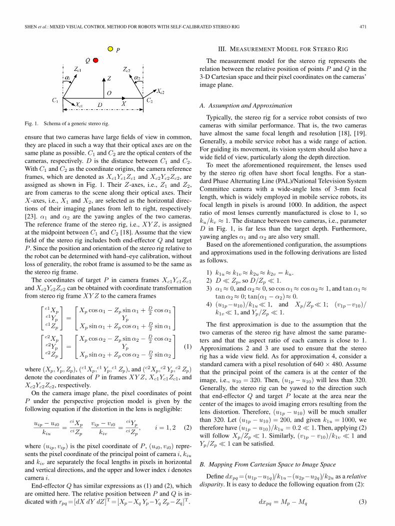
Fig. 1. Schema of a generic stereo rig.
ensure that two cameras have large fields of view in common,they are placed in such a way that their optical axes are on thesame plane as possible. C1 and C2 are the optical centers of thecameras, respectively. D is the distance between C1 and C2.With C1 and C2 as the coordinate origins, the camera referenceframes, which are denoted as Xc1Yc1Zc1 and Xc2Yc2Zc2, areassigned as shown in Fig. 1. Their Z-axes, i.e., Z1 and Z2,are from cameras to the scene along their optical axes. TheirX-axes, i.e., X1 and X2, are selected as the horizontal direc-tions of their imaging planes from left to right, respectively[23]. α1 and α2 are the yawing angles of the two cameras.The reference frame of the stereo rig, i.e., XY Z, is assignedat the midpoint between C1 and C2 [18]. Assume that the viewfield of the stereo rig includes both end-effector Q and targetP . Since the position and orientation of the stereo rig relative tothe robot can be determined with hand–eye calibration, withoutloss of generality, the robot frame is assumed to be the same asthe stereo rig frame.
The coordinates of target P in camera frames Xc1Yc1Zc1
and Xc2Yc2Zc2 can be obtained with coordinate transformationfrom stereo rig frame XY Z to the camera frames⎡
⎣ c1Xpc1Ypc1Zp
⎤⎦ =
⎡⎣Xp cos α1 − Zp sinα1 + D
2 cos α1
Yp
Xp sin α1 + Zp cos α1 + D2 sin α1
⎤⎦
⎡⎣ c2Xp
c2Ypc2Zp
⎤⎦ =
⎡⎣Xp cos α2 − Zp sinα2 − D
2 cos α2
Yp
Xp sin α2 + Zp cos α2 − D2 sin α2
⎤⎦ (1)
where (Xp, Yp, Zp), (c1Xp,c1 Yp,
c1 Zp), and (c2Xp,c2 Yp,
c2 Zp)denote the coordinates of P in frames XY Z, Xc1Yc1Zc1, andXc2Yc2Zc2, respectively.
On the camera image plane, the pixel coordinates of pointP under the perspective projection model is given by thefollowing equation if the distortion in the lens is negligible:
uip − ui0
kiu=
ciXp
ciZp
vip − vi0
kiv=
ciYp
ciZp, i = 1, 2 (2)
where (uip, vip) is the pixel coordinate of P , (ui0, vi0) repre-sents the pixel coordinate of the principal point of camera i, kiu
and kiv are separately the focal lengths in pixels in horizontaland vertical directions, and the upper and lower index i denotescamera i.
End-effector Q has similar expressions as (1) and (2), whichare omitted here. The relative position between P and Q is in-dicated with rpq =[dX dY dZ]T =[Xp−Xq Yp−Yq Zp−Zq]T.
III. MEASUREMENT MODEL FOR STEREO RIG
The measurement model for the stereo rig represents therelation between the relative position of points P and Q in the3-D Cartesian space and their pixel coordinates on the cameras’image plane.
A. Assumption and Approximation
Typically, the stereo rig for a service robot consists of twocameras with similar performance. That is, the two camerashave almost the same focal length and resolution [18], [19].Generally, a mobile service robot has a wide range of action.For guiding its movement, its vision system should also have awide field of view, particularly along the depth direction.
To meet the aforementioned requirement, the lenses usedby the stereo rig often have short focal lengths. For a stan-dard Phase Alternating Line (PAL)/National Television SystemCommittee camera with a wide-angle lens of 3-mm focallength, which is widely employed in mobile service robots, itsfocal length in pixels is around 1000. In addition, the aspectratio of most lenses currently manufactured is close to 1, soku/kv ≈ 1. The distance between two cameras, i.e., parameterD in Fig. 1, is far less than the target depth. Furthermore,yawing angles α1 and α2 are also very small.
Based on the aforementioned configuration, the assumptionsand approximations used in the following derivations are listedas follows.
1) k1u≈ k1v ≈ k2u≈ k2v = ku.2) D � Zp, so D/Zp � 1.3) α1≈ 0, and α2≈ 0, so cos α1≈ cos α2≈ 1, and tan α1≈
tan α2≈ 0; tan(α1 − α2)≈ 0.4) (u1p−u10)/k1u� 1, and Xp/Zp� 1; (v1p−v10)/
k1v � 1, and Yp/Zp � 1.
The first approximation is due to the assumption that thetwo cameras of the stereo rig have almost the same parame-ters and that the aspect ratio of each camera is close to 1.Approximations 2 and 3 are used to ensure that the stereorig has a wide view field. As for approximation 4, consider astandard camera with a pixel resolution of 640 × 480. Assumethat the principal point of the camera is at the center of theimage, i.e., u10 = 320. Then, (u1p − u10) will less than 320.Generally, the stereo rig can be yawed to the direction suchthat end-effector Q and target P locate at the area near thecenter of the images to avoid imaging errors resulting from thelens distortion. Therefore, (u1p − u10) will be much smallerthan 320. Let (u1p − u10) = 200, and given k1u = 1000, wetherefore have (u1p − u10)/k1u = 0.2 � 1. Then, applying (2)will follow Xp/Zp � 1. Similarly, (v1p − v10)/k1v � 1 andYp/Zp � 1 can be satisfied.
B. Mapping From Cartesian Space to Image Space
Define dxpq =(u1p−u1q)/k1u−(u2p−u2q)/k2u as a relativedisparity. It is easy to deduce the following equation from (2):
dxpq = Mp − Mq (3)
472 IEEE TRANSACTIONS ON INSTRUMENTATION AND MEASUREMENT, VOL. 59, NO. 2, FEBRUARY 2010
where Mp = c1Xp/c1Zp− c2Xp/
c2Zp, and Mq = c1Xq/c1Zq−
c2Xq/c2Zq.
Applying (1) to Mp and considering that D � Zp, Mp canbe approximated as
Mp≈D cos(α1 − α2)(1 − F1p)
Zp cos α1 cos α2(4)
where F1p = [Z2p + X2
p − (D/2)2] tan(α1 − α2)/(ZpD).In a similar manner, Mq can be written as follows in the case
D � Zq:
Mq ≈D cos(α1 − α2)(1 − F1q)
Zq cos α1 cos α2(5)
where F1q = [Z2q + X2
q − (D/2)2] tan(α1 − α2)/(ZqD).Substituting (4) and (5) into (3) yields
dxpq ≈D′
Zp(1 − Gp) −
D′
Zq(1 − Gq) (6)
where
D′ =D cos(α1 − α2)cos α1 cos α2
D′ is referred to as equivalent baseline
Gp =X2
p − (D/2)2
DZptan(α1 − α2)
Gq =X2
q − (D/2)2
DZqtan(α1 − α2).
With assumptions 3 and 4 in Section III-A, Gp � 1 andGq � 1 are satisfied. Then, (6) can be further approximatedas follows:
dxpq ≈D′(Zq − Zp)
ZpZq= − D′dZ
Zp(Zp − dZ). (7)
For a stationary target P , (7) indicates the relation betweenrelative depth dZ and variable dxpq.
Substituting (1) into (2) gives Xp and Yp{Xp = (uip−ui0)Zp
kiu(1−Fipu) + Zp tanαi
1−Fipu− D
2
Yp = vip−vi0kiv
Zp cos αi(1 + Fipv)(8)
where Fipu =(uip−ui0) tan αi/kiu, and Fipv =(Xp+D/2)tan αi/Zp, i = 1, 2.
From assumption 3, we have Fipu≈ 0, and Fipv ≈ 0. Then,(8) can be further approximated as{
Xp≈ Zpuip−ui0
kiu+ Zp tan αi − D
2
Yp≈ vip−vi0kiv
Zp.(9)
Then, Xq and Yq can also be derived in a similar way{Xq ≈ Zq
uiq−ui0kiu
+ Zq tan αi − D2
Yq ≈ viq−vi0kiv
Zq.(10)
Subtracting (10) from (9) and rearranging the termsyields (11). It gives the mapping of the relative position betweenP and Q from the Cartesian space to the image space{
uip−uiq
kiu≈ 1
ZpdX − 1
Zp
uiq−(ui0−kiu tanαi)kiu
dZvip−viq
kiv≈ 1
ZpdY − 1
Zp
viq−vi0kiv
dZ.(11)
C. Relative Position Measurement Model
Generally, a typical stereo rig is composed of two cameraswith similar focal lengths. It is a reasonable approximationto set k1u≈ k1v ≈ k2u≈ k2v = ku. Then, multiplying ku onboth sides of (7) and (11) and letting dx′
pq = (u1p − u1q) −(u2p−u2q), u′
10 =u10−ku tan α1, and u′20 =u20−ku tan α2,
the following can be obtained
spq = Apqrpq (12)
where
spq =
⎡⎢⎢⎢⎣
u1p − u1q
v1p − v1q
u2p − u2q
v2p − v2q
dx′pq
⎤⎥⎥⎥⎦
Apq =1Zp
⎡⎢⎢⎢⎣
ku 0 −(u1q − u′10)
0 ku −(v1q − v10)ku 0 −(u2q − u′
20)0 ku −(v2q − v20)0 0 −D′ku/(Zp − dZ)
⎤⎥⎥⎥⎦ .
The vector spq represents the relative position between P andQ on the images of the stereo rig. The vector rpq is the relativeposition between P and Q in the Cartesian space. Therefore,(12) is referred to as the relative position measurement modelfor the stereo rig. Obviously, spq = 0 will be satisfied if andonly if the end-effector reaches the target, i.e., rpq = 0.
IV. STEREO RIG SELF-CALIBRATION
The measurement model (12) is essentially a nonlinear equa-tion. Matrix Apq not only relates to the parameters of the stereorig, such as ku and D′, but also concerns with the positions ofP and Q, i.e., Zp and dZ. To estimate rpq with image featurespq, it is necessary to calibrate the parameters of matrix Apq .
Let Δspqj = spqj − spqj−1 and Δrpqj = rpqj − rpqj−1,which represent the variations in spq and rpq at the jth sam-pling, respectively
Formula (15) indicates that only the movement of end-effector Q accounts for Δspqj and Δrpqj . Δspqj can be deter-mined with image processing and feature extraction, and Δrpqj
can be read from the robot controller. It is possible that theparameters of the stereo rig are calibrated online with Δspqj
and Δrpqj while the robot is moving.Let du1pqj = u1pj − u1qj . From the first row in (12), it is
expressed as follows:
du1pqj =1
Zpj[kudXj − (u1qj − u′
10) dZj ] . (16)
Letting Δdu1pqj = (u1pj − u1qj) − (u1pj−1 − u1qj−1) =du1pqj − du1pqj−1, substituting (16) into (13), and simplifyingit with (13) and (14) gives
Δdu1pqj =1Zp
[kuΔdXj + u′10ΔdZj − u1qj−1ΔdZj
+ Δdu1pqjdZj ] . (17)
Then, Δdu1pqj , which is the first element of Δspqj , can beexpressed as follows with the rearrangement of (17):
Δdu1pqj =1
Zp−dZj[kuΔdXj−(u1qj−1−u′
10) ΔdZj ] . (18)
Similarly, let Δdv1pqj =(v1pj−v1qj)−(v1pj−1−v1qj−1),Δdu2pqj =(u2pj−u2qj)−(u2pj−1−u2qj−1), and Δdv2pqj =(v2pj − v2qj) − (v2pj−1 − v2qj−1); then, Δdv1pqj , Δdu2pqj ,and Δdv2pqj will have the same form as (18).
The equation in the last row of (12) is rewritten as
dx′pqj = − D′kudZj
Zpj(Zpj − dZj). (19)
Letting Δdx′pqj = dx′
pqj − dx′pqj−1 and applying (14) to
(19), we have
Δdx′pqj = − D′ku
Zp
[dZj
Zp − dZj− dZj−1
Zp − dZj−1
]
= − D′ku
Zp
[ΔdZj
Zp − dZj+
dZj−1ΔdZj
(Zp − dZj)(Zp − dZj−1)
]
=1
Zp − dZj
[−D′ku
Zp+dx′
pqj−1
]ΔdZj . (20)
Equations (13), (18), and (20) can be rewritten in matrix formas follows
Vector p involves seven parameters. One step motion of therobot contributes an equation set with five equations, as givenin (23). Therefore, the robot needs to move two steps at least tocalibrate all the unknown parameters.
A. Estimating p6 and p7
The last row of (23) can be decoupled from the others. Thefifth element of the vector Δspqj , i.e., Δdx′
pqj , is only relatedto p6 and p7. The following equation set is formed from twomotion steps according to (23):{
p7Δdx′pqi = −
(p6 − dx′
pqi
) (p6 − dx′
pqi−1
)ΔdZi
p7Δdx′pqi−1 = −
(p6 − dx′
pqi−1
) (p6 − dx′
pqi−2
)ΔdZi−1.
(24)
An equation with only parameter p6 is derived from (24) viaeliminating p7 as follows:
a0p26 + a1p6 + a2 = 0 (25)
where a0 = −ΔdZiΔdx′pqi−1 + ΔdZi−1Δdx′
pqi, a1 = ΔdZi
Δdx′pqi−1(dx′
pqi + dx′pqi−1) − ΔdZi−1Δdx′
pqi(dx′pqi−1 +
dx′pqi−2), a2 = −ΔdZiΔdx′
pqi−1dx′pqidx′
pqi−1 + ΔdZi−1
Δdx′pqidx′
pqi−1dx′pqi−2. Then, the value of p6 listed in the
following is obtained as the solution of (25):
p6 =−a1 ±
√a21 − 4a0a2
2a0. (26)
474 IEEE TRANSACTIONS ON INSTRUMENTATION AND MEASUREMENT, VOL. 59, NO. 2, FEBRUARY 2010
The sign in (26) can be determined by the constraint p6 > 0.Then, p7 can be obtained by substituting p6 into (24); its valueis shown in
p7 =
(p6 − dx′
pqi
) (p6 − dx′
pqi−1
)ΔdZi
Δdx′pqi
. (27)
B. Estimating p1 to p5
Let p′ = [p1, p2, p3, p4, p5]T. Considering the estimated p6
and p7, we can rewrite (23) as the following equation set:
Apip′ = bpi (28)
where
Api =(p6 − dx′
pqi
)
×
⎡⎢⎣
ΔdZi 0 0 0 ΔdXi
0 ΔdZi 0 0 ΔdYi
0 0 ΔdZi 0 ΔdXi
0 0 0 ΔdZi ΔdYi
⎤⎥⎦
bpi =
⎡⎢⎢⎣
p7(u1qi − u1qi−1) +(p6 − dx′
pqi
)u1qi−1ΔdZi
p7(v1qi − v1qi−1) +(p6 − dx′
pqi
)v1qi−1ΔdZi
p7(u2qi − u2qi−1) +(p6 − dx′
pqi
)u2qi−1ΔdZi
p7(v2qi − v2qi−1) +(p6 − dx′
pqi
)v2qi−1ΔdZi
⎤⎥⎥⎦ .
p′ is a 5 × 1 vector, and (28) can contribute four linear equa-tions. Therefore, two motion steps are necessary to determinep′. Providing n ≥ 2, a least-square solution for parametersp1–p5 is given as follows:
p′ =(AT
p Ap
)−1AT
p bp (29)
where Ap =[ATpi,A
Tpi−1, . . . ,A
Tpi−n+1]
T, and bp =[bTpi, b
Tpi−1,
. . . , bTpi−n+1]
T.By combining (26), (27), and (29), the parameters of the
measurement model for the stereo rig can be calibrated onlinewith at least two steps of unspecific motions of the robot.
V. VISUAL CONTROL SCHEME FOR
APPROACH MOVEMENT
A. Position-Based Visual Control System
After the stereo rig is self-calibrated, the relative positionbetween the target and the end-effector of the robot can beestimated with the following measurement model accordingto (12):
rpq =(AT
pqApq
)−1
ATpq spq (30)
where Apq is the estimation of Apq with calibrated parameterp of the stereo rig, and rpq is the estimated relative positionbetween P and Q.
Then, a 3-DOF proportional position-based visual controllaw is designed to guide the end-effector to reach the positionof a fixed target according to rpq
u1 = Kp1rpq = K′p1spq (31)
Fig. 2. Position-based visual control system. (a) With the stereo rig calibratedin advance. (b) With a self-calibrated stereo rig.
where
Kp1 =
⎡⎣ kp1x 0 0
0 kp1y 00 0 kp1z
⎤⎦
is the proportional coefficient matrix, K′p1 =Kp1(AT
pqApq)−1
ATpq , and u1 is a 3 × 1 offset vector to control the robot to move
along the X-, Y -,and Z-axes in incremental movement mode.The block diagram of the position-based visual control sys-
tem is shown in Fig. 2. It has the form of an end-point closedloop, that is, the stereo rig observes both the target and the end-effector. Fig. 2(a) gives the block diagram of the position-basedvisual control system with a stereo rig calibrated in advance.Fig. 2(b) is the proposed visual control system with the self-calibrated stereo rig, which is improved from Fig. 2(a). Thesystem consists of a self-calibration module E, a proportionalcontroller Kp1, a 3-D Cartesian space relative position estimatorF (p) = (AT
pqApq)−1ATpq, a robot R, a stereo rig, and a feature
extraction module Apq(p). Among these modules, F(p) acts asthe reverse model of Apq(p). It estimates the relative positionbetween the target and the end-effector in the 3-D Cartesianspace with vector p and image features.
The vision system parameters are calibrated online with themotion information of the robot, i.e., Δrpq , and image featurespq. The pixel coordinates of the end-effector and the targetare extracted through image processing to obtain image featurevector spq , which serves as the visual feedback. The propor-tional controller generates incremental movement u1 accordingto rpq , which is utilized to control the robot to move toward thetarget with a traditional joint controller working in incrementalmovement control mode.
B. Image-Based Visual Control System at Initialization
The self-calibration of the vision system needs at least twosteps of movement of the robot. In other words, the parametersare unavailable until the robot moves by at least two steps.The position-based visual control law presented above cannotwork without these parameters. This process is characterized asthe initialization. At this stage, the robot needs another controllaw, which can not only make the self-calibration component
SHEN et al.: MIXED VISUAL CONTROL METHOD FOR ROBOTS WITH SELF-CALIBRATED STEREO RIG 475
achieve the initialization but also prevent the robot from movingaway from the target.
The image-based visual control method requires neither theCartesian reconstruction nor the camera parameters. Therefore,it is an appropriate control method for the initializing process.Let dui = uip − uiq and dvi = vip − viq , i = 1, 2. From (12),we have
fpq = Lpq(rpq)rpq (32)
where
fpq =
⎡⎣ du1 + du2
dv1 + dv2
du1 − du2
⎤⎦
Lpq(rpq) =2ku
Zp
⎡⎢⎢⎣
1 0 − (u1q−u′10)+(u2q−u′
20)2ku
0 1 − (v1q−v10)+(v2q−v20)2ku
0 0 − D′
2(Zp−dZ)
⎤⎥⎥⎦ .
From assumption 4 in Section III-A, the following approxi-mation can be satisfied:
− (u1q − u′10) + (u2q − u′
20)2ku
� 1
− (v1q − v10) + (v2q − v20)2ku
� 1. (33)
Letting L∗pq = Lpq(0) be the estimation of Lpq(rpq) and
applying (33) to L∗pq, it follows that
L∗pq =
⎡⎣ k1 0 0
0 k1 00 0 k2
⎤⎦ (34)
where k1 = 2ku/Zp, and k2 = D′ku/Z2p .
Assume that the target is fixed and the parameters of thestereo rig are unchangeable, i.e., Zp, ku, and D′ are posi-tive constants. Then, coefficients k1 and k2 are also positiveconstants, and L∗
pq is a reversible constant matrix. With L∗pq,
a proportional image-based visual control law is designed asfollows:
u2 = Kp2
(L∗
pq
)−1fpq = K′
p2fpq (35)
where
Kp2 =
⎡⎣ kp2x 0 0
0 kp2y 00 0 kp2z
⎤⎦
is the proportional coefficient matrix, and K′p2 = Kp2(L∗
pq)−1.
The block diagram of the image-based visual control systemis given in Fig. 3. Since L∗
pq and Kp2 are both diagonal matrices,
Fig. 3. Block diagram of an image-based visual control system.
Fig. 4. Block diagram of a mixed visual control system.
each of the 3 DOFs of the end-effector can be decoupled withone element of image feature vector fpq.
C. Mixed Visual Control System
Combining (31) and (35) gives the following visual controllaw for guiding the robot to approach the target:
u = [Tp I3 − Tp] ·[
u1
u2
](36)
where I3 is a 3 × 3 identity matrix,
Tp =
⎡⎣ tpx 0 0
0 tpy 00 0 tpz
⎤⎦
is the switch matrix, and
tpi ={
1, if the calibration result is valid0, else
where i = x, y, z.Fig. 4 shows the schema of the mixed visual control system.
Switch module W monitors the validness of the self-calibratedresults. When the parameters of the stereo rig are successfullyestimated, the position-based visual control law will be se-lected, i.e., u = u1. Since the relative position between end-effector Q and target P can directly be obtained from (30)with the self-calibrated stereo rig, the motion efficiency willbe improved. If the online calibration has failed because ofthe noise, the switch module will take u = u2. Then, theimage-based visual control law will be adopted to increase therobustness.
The control strategy presented in (36) integrates the position-based and image-based visual control methods. It can improveboth the efficiency and the robustness of the system.
476 IEEE TRANSACTIONS ON INSTRUMENTATION AND MEASUREMENT, VOL. 59, NO. 2, FEBRUARY 2010
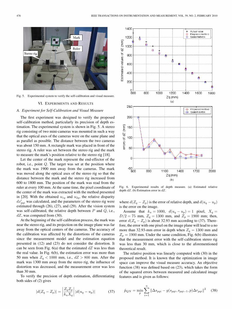
Fig. 5. Experimental system to verify the self-calibration and visual measure.
VI. EXPERIMENTS AND RESULTS
A. Experiment for Self-Calibration and Visual Measure
The first experiment was designed to verify the proposedself-calibration method, particularly its precision of depth es-timation. The experimental system is shown in Fig. 5. A stereorig consisting of two mini-cameras was mounted in such a waythat the optical axes of the cameras were on the same plane andas parallel as possible. The distance between the two cameraswas about 150 mm. A rectangle mark was placed in front of thestereo rig. A ruler was set between the stereo rig and the markto measure the mark’s position relative to the stereo rig [18].
Let the center of the mark represent the end-effector of therobot, i.e., point Q. The target was set at the position wherethe mark was 1900 mm away from the cameras. The markwas moved along the optical axes of the stereo rig so that thedistance between the mark and the stereo rig increased from600 to 1800 mm. The position of the mark was read from theruler at every 100 mm. At the same time, the pixel coordinate ofthe center of the mark was extracted with the method presentedin [20]. With the obtained u1q and u2q, the relative disparitydx′
pqi was calculated, and the parameters of the stereo rig wereestimated through (26), (27), and (29). After the vision systemwas self-calibrated, the relative depth between P and Q, i.e.,dZ, was computed from (30).
At the beginning of the self-calibration process, the mark wasnear the stereo rig, and its projection on the image plane was faraway from the optical centers of the cameras. The accuracy ofthe calibration was affected by the distortions of the camerassince the measurement model and the estimation equationpresented in (12) and (23) do not consider the distortion. Itcan be seen from Fig. 6(a) that the estimated dZ was less thanthe real value. In Fig. 6(b), the estimation error was more than50 mm when Zq < 1000 mm, i.e., dZ > 800 mm. After themark was 1300 mm away from the stereo rig, the influence ofdistortion was decreased, and the measurement error was lessthan 30 mm.
To verify the precision of depth estimation, differentiatingboth sides of (2) gives
|d(Zq − Zp)| =∣∣∣∣ZqZp
kuXq
∣∣∣∣ |d(uq − up)| (37)
Fig. 6. Experimental results of depth measure. (a) Estimated relativedepth dZ. (b) Estimation error in dZ.
where d(Zq − Zp) is the error of relative depth, and d(uq − up)is the error on the image.
Assume that ku = 1000, d(uq − up) = 1 pixel, Xq =D/2 = 75 mm, Zq = 1300 mm, and Zp = 1900 mm; then,error d(Zq − Zp) is about 32.93 mm according to (37). There-fore, the error with one pixel on the image plane will lead to a nomore than 32.93-mm error in depth when Zq = 1300 mm andZp = 1900 mm. Under the same condition, Fig. 6(b) illustratesthat the measurement error with the self-calibration stereo rigwas less than 30 mm, which is close to the aforementionedtheoretical result.
The relative position was linearly computed with (30) in theproposed method. It is known that the optimization in imagespace can improve the visual measure accuracy. An objectivefunction (38) was defined based on (23), which takes the formof the squared errors between measured and calculated imagefeatures and is given as follows:
pQN = minp
n∑i=1
‖Δspqi − g(spqi, spqi−1, p)Δrpqi‖2 (38)
SHEN et al.: MIXED VISUAL CONTROL METHOD FOR ROBOTS WITH SELF-CALIBRATED STEREO RIG 477
TABLE IRELATIVE POSITION MEASURING RESULTS WITH SELF-CALIBRATION
AND THE RESULTS AFTER QUASI-NEWTON OPTIMIZATION
Fig. 7. Scene of the experimental system.
where pQN is the local minimum of the objective function. Aquasi-Newton method was employed to optimize the objectivefunction (38) to improve the position measure precision, whoseresults were used to compare and assess the position measureresults with the proposed method.
The measurement results after the optimization with thequasi-Newton method are also shown in Fig. 6 and listed inTable I. It can be seen from Fig. 6 and Table I that the positionmeasure results with the proposed method has almost the sameprecision as the results after the optimization in the image spacewith the quasi-Newton method. In other words, the proposedmeasurement method with the self-calibration stereo rig hasgood measure accuracy.
B. Visual Control Experiments for Robot Approaching
In visual control experiments, the task was to control the end-effector marked with red color to approach a yellow ball. Thevisual control system consisted of a UP6 industrial manipulator,a robot controller, a host computer, an OK_MC30 four-channelframe grabber, and a stereo rig, as shown in Fig. 7. Thecomputer was connected to the robot controller through anRS-232 serial communication interface. The motion commandsin the 3-D Cartesian space for the robot were transferredfrom the computer to the robot controller. The robot controller
Fig. 8. Approaching results of the comparative experiments.
converted these commands into joint positions and drove themanipulator to the specified position.
The yellow ball was placed in front of the robot, serving astarget P . A red mark was attached at the end of the manipulatorto identify the position of the robot, i.e., point Q. The stereorig, which was the same as the one used in Section VI-A, wasfixed behind the foundation of the robot, as shown in Fig. 7. Thehand–eye geometry between the stereo rig and the robot couldbe approximated as follows:
cRr =
⎡⎣ 0 −1 0
0 0 −11 0 0
⎤⎦ . (39)
The ball and the mark were identified based on their color,and the pixel coordinates of their center were obtained atPAL frame rate (25 Hz). The host computer used the imageinformation and the current position of the robot read from therobot controller to calibrate the stereo rig online. The robotwas guided to the ball with the mixed visual control systemin Section V-C. The maximum moving step length of the robotwas limited to 100 mm for the sake of safety. The proportionalcoefficient matrix in (31) and (35) was set as follows:
Kp1 =
⎡⎣ 0.5 0 0
0 0.5 00 0 0.5
⎤⎦ K′
p2 =
⎡⎣ 1.0 0 0
0 1.0 00 0 1.0
⎤⎦ . (40)
Experimental results are shown in Fig. 8. The first twosteps of the movement were the initialization stage for theself-calibration algorithm and the employment of the image-based visual control law (35). Then, the robot moved underthe position-based visual control law (31) with the online-calibrated stereo rig. After 19 steps, the end-effector arrived atthe ball, and the approaching task was finished.
To compare the performance of the proposed mixed visualcontrol method with those of traditional visual control methods,a series of experiments with the same aforementioned ap-proaching task was conducted with position-based and image-based methods, respectively.
478 IEEE TRANSACTIONS ON INSTRUMENTATION AND MEASUREMENT, VOL. 59, NO. 2, FEBRUARY 2010
TABLE IICAMERAS’ PARAMETERS OF THE STEREO RIG
TABLE IIISPEED AND ERRORS IN COMPARISON EXPERIMENTS
The block diagram of the position-based visual control sys-tem in comparison experiments was as given in Fig. 2(a). Itsparameters of the stereo rig were calibrated offline with theMatlab calibration toolbox [21], as listed in Table II. The 3-DCartesian space relative position estimator F (p) was computedfrom the parameters of the stereo rig and the image coordinatesof end-effector Q and target P . The control law was as givenin (31). The proportional coefficient matrix Kp1 was selectedas given in (40).
In comparative experiments with the image-based visualcontrol system, the robot was guided to the ball with the methodin Section V-B. The block diagram of the image-based visualcontrol system in comparison experiments was as given inFig. 3. The control law and its parameters were selected as (35)and (40), which were the same as those used in the initializationstage of the presented mixed method.
The approaching trajectory results of the comparison exper-iments are shown in Fig. 8. It can be seen that the trajectoryat the beginning stage with the mixed control method wasclose to that with the image-based control method. Then, thetrajectory with the mixed control method was close to thatwith the position-based method. Despite its trajectory on theY -axis being less smooth because of image noises, with theself-calibrated stereo rig, the proposed mixed method did notrequire the cameras’ calibration prior to the running of thesystem. On the other hand, compared with the image-basedmethod, the proposed method more quickly converged, par-ticularly along the direction of the Z-axis, since it could esti-mate the depth between the end-effector and the target in the3-D Cartesian space. The approaching steps needed for thesethree visual control methods, as well as the reached positionsand errors, are listed in Table III. The steps needed in theapproaching experiments were 9, 31, and 19 for the position-based, the image-based, and the proposed method, respectively.The target was at the position (590, −420, 730) mm. Theapproaching errors were 25.77, 89.38, and 17.76 mm for theposition-based, the image-based, and the proposed method,respectively. The error for the image-based method was mainlyin the Z-axis of the reference frame.
The experimental result indicates that the proposed mixedvisual control method avoids calibrating the vision system inadvance. Therefore, the flexibility of mobile service robots withthe self-calibrating stereo rig can be increased.
When a mobile service robot approaches and operates anobject such as a doorknob or a tea cup with its manipulator,it can actively yaw the stereo rig to an adequate directionand adjust the focal lengths of the cameras to have goodimages of the object. The stereo rig can be self-calibrated atthe beginning stage in the approaching process controlled withthe proposed mixed visual control method. Then, the relativeposition between the robot’s end-effector and the target canbe estimated. The proposed methods can ensure that the end-effector quickly, robustly, and accurately reaches the target.
It should be noticed that this paper only discusses the self-calibration of the stereo rig itself. The hand–eye calibration ofthe system is still required. Another limitation is that the visualcontrol law is only applicable to 3-DOF translation movementsof the robot, which is usually the first stage of the approach-to-grasp task for a mobile service robot.
VII. CONCLUSION AND FUTURE WORK
In this paper, a relative position measurement model fora stereo rig has been proposed. The relative position in theCartesian space between the target and the end-effector isrelated to their pixel coordinates. By defining relative disparity,the depth information can be decoupled with the other imagefeatures, and the measuring accuracy can be improved. A self-calibration algorithm has been developed. The parameters ofthe stereo rig are linearly estimated with two unspecific motionsteps of the robot. The algorithm only requires solving a linearequation set. Hence, it is more computationally efficient thantraditional nonlinear optimization methods such as a quasi-Newton method but can achieve almost the same accuracy.
Based on the self-calibrated stereo rig, a mixed visual controlmethod has been presented for the approach movement of therobot. The robustness and efficiency of the system are improvedby taking the advantages of both position-based and image-based visual control methods. Experimental results indicatethat the proposed mixed visual control method is more flexiblewith the camera parameters than the position-based method andmore quickly converges than the image-based method.
Our future work will focus on developing a fully automatichand–eye calibration method based on active vision techniquesand a special visual control law to achieve 6-DOF control forthe robot.
REFERENCES
[1] A. Hauck, M. Sorg, G. Farber, and T. Schenk, “What can be learnedfrom human reach-to-grasp movements for the design of robotic hand-eye system?” in Proc. IEEE Int. Conf. Robot. Autom., Detroit, MI, 1999,pp. 2521–2526.
[2] G. D. Hager, S. A. Hutchinson, and P. I. Corke, “A tutorial on visualservo control,” IEEE Trans. Robot. Autom., vol. 12, no. 5, pp. 651–670,Oct. 1996.
[3] D. Kragic and H. Christensen, “Survey on visual servoing for manipula-tion,” Comput. Vis. Active Perception Lab. (CVAP), Stockholm, Sweden,Tech. Rep., ISRN KTH/NA/P-02/01-SE, 2002. CVAP259.
[4] F. Chaumette and S. A. Hutchinson, “Visual servo control. Part I: Basicapproaches,” IEEE Robot. Autom. Mag., vol. 13, no. 4, pp. 82–90,Dec. 2006.
[5] E. Malis, “Survey of vision-based robot control,” in Proc. Eur. Naval ShipDes. Captain Comput. IV Forum, Brest, France, 2002.
[6] D. Kragic, A. T. Miller, and P. K. Allen, “Real-time tracking meets onlinegrasp planning,” in Proc. IEEE Int. Conf. Robot. Autom., Seoul, Korea,2001, pp. 2460–2465.
SHEN et al.: MIXED VISUAL CONTROL METHOD FOR ROBOTS WITH SELF-CALIBRATED STEREO RIG 479
[7] M. Han, S. Lee, S.-K. Park, and M. Kim, “A new landmark-based visualservoing with stereo camera for door opening,” in Proc. Int. Conf. Control,Autom. Syst., Jeonbuk, Korea, 2002, pp. 1892–1896.
[8] B. Espiau, F. Chaumette, and P. Rives, “A new approach to visual servoingin robotics,” IEEE Trans. Robot. Autom., vol. 8, no. 3, pp. 313–326,Jun. 1992.
[9] N. Gan, P. I. Corke, and S. A. Hutchinson, “Comparison of robustness andperformance of partitioned image based visual servo systems,” in Proc.Australian Conf. Robot. Autom., Sydney, Australia, 2001, pp. 73–78.
[10] F. Chaumette, “Potential problems of stability and convergence in image-based and position-based visual servoing,” in Proc. Workshop Vis. Con-trol, Block Island, RI, 1997.
[11] E. Malis, F. Chaumette, and S. Boudet, “2-1/2-D visual servoing,” IEEETrans. Robot. Autom., vol. 15, no. 2, pp. 234–246, Apr. 1999.
[12] N. Maru, H. Kase, S. Yamada, A. Nishikawa, and F. Miyazaki, “Manipu-lator control by visual servoing with the stereo vision,” in Proc. IEEE/RSJInt. Conf. Intell. Robots Syst., Yokohama, Japan, 1993, pp. 1866–1870.
[13] E. Grosso, G. Metta, A. Oddera, and G. Sandini, “Robust visual servoingin 3D reaching tasks,” IEEE Trans. Robot. Autom., vol. 12, no. 5, pp. 732–741, Oct. 1996.
[14] G. D. Hager, W. C. Chang, and A. S. Morse, “Robot hand-eye coordinatebased on stereo vision,” IEEE Control Syst. Mag., vol. 15, no. 1, pp. 30–39, Feb. 1995.
[15] N. P. Papanikolopoulos and P. K. Khosla, “Adaptive robotic visual track-ing: Theory and experiments,” IEEE Trans. Robot. Autom., vol. 38, no. 3,pp. 429–445, Mar. 1993.
[16] J. A. Piepmeier, G. V. McMurray, and H. Lipkin, “Uncalibrated dynamicvisual servoing,” IEEE Trans. Robot. Autom., vol. 20, no. 1, pp. 143–147,Feb. 2004.
[17] J. Qian and J. B. Su, “Online estimation of image Jacobian matrix byKalman-Bucy filter for uncalibrated stereo vision feedback,” in Proc.IEEE Int. Conf. Robot. Autom., Washington, DC, 2002, pp. 562–567.
[18] D. Xu, Y. F. Li, M. Tan, and Y. Shen, “A new active visual system forhumanoid robots,” IEEE Trans. Syst., Man, Cybern. C, Appl. Rev., vol. 38,no. 2, pp. 320–330, Apr. 2008.
[19] D. Kragic, M. Bjorkman, H. I. Christensen, and J.-O. Eklundh, “Visionfor robotic object manipulation in domestic settings,” Robot. Auton. Syst.,vol. 52, no. 1, pp. 85–100, Jul. 2005.
[20] S. M. Smith and J. M. Brady, “SUSAN—A new approach to low-level image processing,” Int. J. Comput. Vis., vol. 23, no. 1, pp. 45–78,May 1997.
[21] J. Y. Bouguet, Camera Calibration Toolbox for Matlab. [Online]. Avail-able: http://www.vision.caltech.edu/bouguetj/calib_doc/index.html
[22] Y. K. Yu, K. H. Wong, S. H. Or, and M. M. Y. Chang, “Robust 3-D motiontracking from stereo images: a model-less method,” IEEE Trans. Instrum.Meas., vol. 57, no. 3, pp. 622–630, Mar. 2008.
[23] R. Hartley and A. Zisserman, Multiple View Geometry in ComputerVision. Cambridge, U.K.: Cambridge Univ. Press, 2004.
Yang Shen received the B.Sc. degree from the Uni-versity of Science and Technology of China, Hefei,China, in 2002 and the Ph.D. degree in controlscience and engineering from the Institute ofAutomation, Chinese Academy of Sciences, Beijing,China, in 2007.
His research interests include robotics andautomation.
De Xu received the B.Sc. and M.Sc. degrees incontrol science and engineering from Shandong Uni-versity of Technology, Jinan, China, in 1985 and1990, respectively, and the Ph.D. degree in controlscience and engineering from Zhejiang University,Hangzhou, China, in 2001.
Since 2001, he has been with the Institute ofAutomation, Chinese Academy of Sciences, Beijing,China, where he is currently a Professor with theLaboratory of Complex Systems and IntelligenceScience. His research interests include robotics and
automation, particularly the control of robots such as visual control andintelligent control.
Min Tan received the B.Sc. degree in control scienceand engineering from Tsinghua University, Beijing,China, in 1986 and the Ph.D. degree in controlscience and engineering from the Institute of Au-tomation, Chinese Academy of Sciences, (IACAS),Beijing, China, in 1990.
He is currently a Professor with the Laboratory ofComplex Systems and Intelligence Science, IACAS.He is the author of more than 100 papers in journals,books, and conference proceedings. His researchinterests include robotics and intelligent control
systems.
Junzhi Yu received the B.E. degree in safety engi-neering and the M.E. degree in precision instrumentsand mechanology from the North China Institute ofTechnology, Taiyuan, China, in 1998 and 2001, re-spectively, and the Ph.D. degree in control theory andcontrol engineering from the Institute of Automation,Chinese Academy of Sciences (IACAS), Beijing,China, in 2003.
After graduation, he served as a Postdoctoral Re-searcher with the Center for Systems and Control,Peking University, Beijing. He was a Research Fel-
low from March 5 to August 4, 2008 with the City University of HongKong, Kowloon, Hong Kong. He is currently an Associate Professor with theLaboratory of Complex Systems and Intelligence Science, IACAS. His researchinterests include biomimetic robots, multirobot systems, and intelligent infor-mation processing.