- 39 - Proceeding of ’99 Korea-Japan Joint Seminar on Particle Image Velocimetry pp39-50 Mixing Process in the Jet Flow of Lobed Nozzle Tetsuo SAGA, Hui HU and Toshio KOBAYASHI Institute of Industrial Science, University of Tokyo 7-22-1 Roppongi, Tokyo 106, Japan Abstract The vortical and turbulent structure changes in the near field (X/D<3.0) of the jet mixing flow caused by a lobed nozzle had been investigated experimentally in the present study. The techniques of planar Laser Induced Fluoresce (LIF) and Particle Image Velocimetry (PIV) were used to accomplish the flow visualization and velocity field measurements. The experimental results showed that, compared with a circular jet flow, lobed jet mixing flow was found to have shorter laminar region, smaller scale of the spanwise Kelvin-Helmholtz vortices, earlier appearance of small scale turbulent structures and larger intensive mixing region in the near field of the jet mixing flow. The central line velocity decay of the lobed jet mixing flow was also found to be much faster than that in a conventional circular jet. All these indicted the better mixing enhancement performance of a lobed nozzle over a conventional circular nozzle. Keywords: Jet mixing flow, jet mixing enhancement, Lobed nozzle, PIV technique and LIF technique Introduction The physics of mixing layer is of considerable interest from both fundamental and practical points of view. It has been widely suggested that mixing process be intimately connected with transient of turbulence. In the engineering flows, mixing process govern the mixing rate in the combustion chambers, jet noise level of the airplane and vehicles, and the spread of pollutant at industrial sites. The research for understanding the physics of the mixing process and revealing the mechanism for the mixing enhancement are very necessary and important for many engineering applications, such as combustion efficiency improvement, jet noise suppression and size reduction of such functional devices. During the past decades, it has became clear that an enormously powerful mechanism for enhancing flow mixing is generation the streamwise vortices in a mixing flow by using some vortex generators such as lobed nozzles. Investigating the evolution of various vortices in a lobed jet mixing flow and interaction between these vortices to reveal the changes of turbulent and vortical structures in a lobed jet mixing flow compared with conventional jet are the subjects of present study. A lobed nozzle, which consists of a splitter plate with convoluted trailing edge, is an extraordinary fluid mechanic device for efficient mixing of two co-flow streams with different velocity, temperature and/or spices. Such device had been known since the earliest days of jet engines and received considerable attention for reducing jet noise since the 1960’s. More recently, it has emerged as an attractive approach for mixing the core and bypass streams of turbofan engines to improve propulsion efficiency, reduce the specific fuel consumption (SFC) and suppress the infrared radiation emission (Power et al. 1994, Presz et al.1994 and Hu et al.1996). Lobed nozzle/mixer has also been received attention for using in supersonic ejectors for jet noise reduction at aircraft take off and landing as well as in combustion chamber for enhancing mixing between fuel and air (Tillman et al.1993 and Smith et al.1997). About the researches to reveal the mechanism of the mixing enhancement of a lobed nozzle/mixer, Paterson (1982) is the first one to measure the velocity and turbulent characteristics downstream of a lobed nozzle/mixer systemically by using Laser Doppler Velocimetry (LDV). He concluded that a lobed nozzle/mixer could cause large-scale streamwise vortices shed at the trailing edge of lobes. So the downstream of flow field is embedded with many array of large-scale streamwise vortices of alternating sign, which are believed to be primarily responsible for the enhanced mixing. The study of McCormick et al. (1994) revealed more details for the flow patterns downstream of a lobed nozzle/mixer. Based on the pulsed-laser sheet flow visualization with smoke and three dimensional velocity measurements with Hot Film Anemometer (HFA), they suggested that the interaction of Kelvin-helmholtz (spanwise) vortices with the streamwise
Transcript
- 39 -
Proceeding of ’99 Korea-Japan Joint Seminaron Particle Image Velocimetry pp39-50
Mixing Process in the Jet Flow of Lobed Nozzle
Tetsuo SAGA, Hui HU and Toshio KOBAYASHI
Institute of Industrial Science, University of Tokyo7-22-1 Roppongi, Tokyo 106, Japan
AbstractThe vortical and turbulent structure changes in the near field (X/D<3.0) of the jet mixing flow caused by a lobed nozzle
had been investigated experimentally in the present study. The techniques of planar Laser Induced Fluoresce (LIF) andParticle Image Velocimetry (PIV) were used to accomplish the flow visualization and velocity field measurements. Theexperimental results showed that, compared with a circular jet flow, lobed jet mixing flow was found to have shorter laminarregion, smaller scale of the spanwise Kelvin-Helmholtz vortices, earlier appearance of small scale turbulent structures andlarger intensive mixing region in the near field of the jet mixing flow. The central line velocity decay of the lobed jet mixingflow was also found to be much faster than that in a conventional circular jet. All these indicted the better mixingenhancement performance of a lobed nozzle over a conventional circular nozzle.
IntroductionThe physics of mixing layer is of considerable interest from both fundamental and practical points of view. It has been
widely suggested that mixing process be intimately connected with transient of turbulence. In the engineering flows,mixing process govern the mixing rate in the combustion chambers, jet noise level of the airplane and vehicles, and thespread of pollutant at industrial sites. The research for understanding the physics of the mixing process and revealing themechanism for the mixing enhancement are very necessary and important for many engineering applications, such ascombustion efficiency improvement, jet noise suppression and size reduction of such functional devices.
During the past decades, it has became clear that an enormously powerful mechanism for enhancing flow mixing isgeneration the streamwise vortices in a mixing flow by using some vortex generators such as lobed nozzles. Investigatingthe evolution of various vortices in a lobed jet mixing flow and interaction between these vortices to reveal the changes ofturbulent and vortical structures in a lobed jet mixing flow compared with conventional jet are the subjects of presentstudy.
A lobed nozzle, which consists of a splitter plate with convoluted trailing edge, is an extraordinary fluid mechanicdevice for efficient mixing of two co-flow streams with different velocity, temperature and/or spices. Such device had beenknown since the earliest days of jet engines and received considerable attention for reducing jet noise since the 1960’s.More recently, it has emerged as an attractive approach for mixing the core and bypass streams of turbofan engines toimprove propulsion efficiency, reduce the specific fuel consumption (SFC) and suppress the infrared radiation emission(Power et al. 1994, Presz et al.1994 and Hu et al.1996). Lobed nozzle/mixer has also been receivedattention for using insupersonic ejectors for jet noise reduction at aircraft take off and landing as well as in combustion chamber for enhancingmixing between fuel and air (Tillman et al.1993 and Smith et al.1997).
About the researches to reveal the mechanism of the mixing enhancement of a lobed nozzle/mixer, Paterson (1982) is thefirst one to measure the velocity and turbulent characteristics downstream of a lobed nozzle/mixer systemically by usingLaser Doppler Velocimetry (LDV). He concluded that a lobed nozzle/mixer could cause large-scale streamwise vorticesshed at the trailing edge of lobes. So the downstream of flow field is embedded with many array of large-scale streamwisevortices of alternating sign, which are believed to be primarily responsible for the enhanced mixing.
The study of McCormick et al. (1994) revealed more details for the flow patterns downstream of a lobed nozzle/mixer.Based on the pulsed-laser sheet flow visualization with smoke and three dimensional velocity measurements with Hot FilmAnemometer (HFA), they suggested that the interaction of Kelvin-helmholtz (spanwise) vortices with the streamwise
- 40 -
vortices produces the high levels of mixing. The streamwise vortices deform the normal vortices into pinch-off structuresand increase the stirring effect in the mixing flow. These result in the creation of intense small-scale turbulence and mixing.
In the paper of the Belovich et al.(1997), the results of these previous researches were summarized as that the mixingprocess in a lobed nozzle/mixer is controlled by three primary elements. The first is the streamwise vortices generated dueto the lobed shape. The second is the increasement in interfacial area between the two flows due to the special geometry ofthe lobed structure, and the third is the Brown-Roshiko type structures which occurring in any shear layer due to theKelvin-Helmholtz instabilities.
Although many important results had been got through these investigations, much work still need to understand the fluiddynamic mechanism of mixing enhancement by a lobed nozzle more clearly, especially about the vortical and turbulentstructure changes in a lobed jet mixing flow compared with a conventional jet flow. In the meanwhile, most of the previousresearches were conducted by using Pitot probe, Laser Doppler Velocimetry(LDV) or Hot Film Anemometer (HFA), whichare very hard to reveal the vortical and turbulent structures in lobed jet mixing flows instantaneously and globally due to thelimitation of these experimental techniques. In the present study, both planar Laser Induced Fluorescence (LIF) and ParticleImage Velocimetry (PIV) techniques were used to study the lobed jet mixing flows instantaneously and globally. By usingthe directly perceived LIF flow visualization images, velocity fields, vorticity distributions and turbulence intensitydistributions of PIV measurement results, the evolution and interaction characteristics of the spanwise Kelvin-Helmholtzvortices with streamwise vortices in the lobed jet mixing flow were studied. The changes of the turbulent and vorticalstructures in the near field of jet mixing flow caused by a lobed nozzle were discussed in detail.
Experimental set-upFigure 1 shows the schematically experimental set-up used in the present study. The test nozzles were installed in the
middle of the water tank (600mm*600mm*1000mm). Fluorescent dye (Rhodamine B) for LIF or PIV tracers (polystyreneparticles of d=20-30�m, density is 1.02kg/cm3) was premixed with water in jet supply tank, and jet flow was supplied by apump. The flow rate of the jet, which was used to calculate the representative velocity and Reynolds numbers, wasmeasured by a flow meter. Convergent unit and honeycomb structures were installed at the inlet of test nozzles to insure theturbulence intensity levels of jet flows at the exit of test nozzles were less than 3%.
The pulsed laser sheet (thickness is about 1.0 mm) used for LIF visualization and PIV measurement was supplied by twinNd:YAG Lasers with the frequency of 10 Hz and power of 200 mJ/pulse. The time interval between the two pulses can beadjustable. 1008 by 1016 pixels Cross-Correlation CCD array camera (PIVCAM 10-30) were used to capture the LIF andPIV images. The twin Nd:YAG Lasers and the CCD camera were controlled by a Synchronizer Control System. The LIFand PIV images captured by the CCD camera were digitized by an image processing board, then transferred to a workstation (CPU450MHz, RAM 1024MB, HD20GB) for image processing and displayed on a PC monitor.
Rhodamine B was used as fluorescent dye in the present experiment. The fluorescent light (�f=590nm) was separatedfrom the scattered laser light(�l=532nm) by installation a high pass optical filter at the head of the CCD camera. A lowconcentration Rhodamine B solution (0.5mg/l) was used to insure the strength of fluorescent light being linear with theconcentration of the fluorescent dye and the effect of laser light attenuation being negligible as the laser light sheetpropagated through the flow (Hu et al. 1999).
For the PIV image processing, rather than tracking individual particle, cross correlation method (Willert et al., 1991) wasused in the present study to obtain the average displacement of the ensemble particles. The images were divided into 32 by32 pixel interrogation windows, and 50% overlap grids were employed. The resolution the PIV images for the presentresearch is about 120�m/pixel. The post-processing procedures which including sub-pixel interpolation (Hu et al., 1998)and velocity outliner deletion (Westerweel, 1994) were used to improve the accuracy of the PIV result.
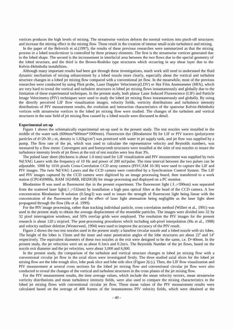
Figure 2 shows the two test nozzles used in the present study: a baseline circular nozzle and a lobed nozzle with six lobes.The height of the lobes is 15mm and the inner and outer penetration angles of the lobe structures are about 220 and 140
respectively. The equivalent diameters of these two nozzles at the exit were designed to be the same, i.e. D=40mm. In thepresent study, the jet velocities were set as about 0.1m/s and 0.2m/s. The Reynolds Number of the jet flows, based on thenozzle exit diameter and the jet velocities, were about 3,000 and 6,000.
In the present study, the comparison of the turbulent and vortical structure changes in lobed jet mixing flow with aconventional circular jet flow in the axial slices were investigated firstly. The three studied axial slices for the lobed jetmixing flow are the lobe trough slice, lobe peak slice and lobe side slice (Figure 2(c).). Then, the LIF flow visualization andPIV measurement at several cross sections for the lobed jet mixing flow and conventional circular jet flow were alsoconducted to reveal the changes of the vortical and turbulent structures in the cross planes of the jet mixing flow.
For the PIV measurement results, the time average values, which include the mean velocity vectors, mean streamwisevorticity distributions and mean turbulence intensity fields, were also used to compare the mixing characteristics in thelobed jet mixing flows with conventional circular jet flow. These mean values of the PIV measurement results werecalculated based on the average of 400 frames of the instantaneous PIV velocity fields, which were obtained at the
- 41 -
frequency of 10 Hz.It had been found that the intensive mixing of the core jet flow with ambient flows could be achieved in the very near
field of the jet flow by using a lobed nozzle/mixer. So, the CCD camera view were set at the near region (X/D<3.0) of thejet mixing flow in the present study.
Results and discussion1. In the axial slices
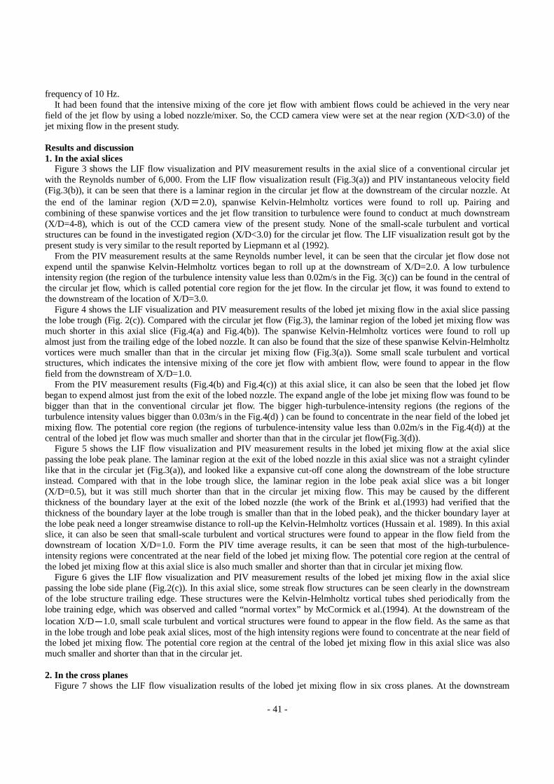
Figure 3 shows the LIF flow visualization and PIV measurement results in the axial slice of a conventional circular jetwith the Reynolds number of 6,000. From the LIF flow visualization result (Fig.3(a)) and PIV instantaneous velocity field(Fig.3(b)), it can be seen that there is a laminar region in the circular jet flow at the downstream of the circular nozzle. Atthe end of the laminar region (X/D�2.0), spanwise Kelvin-Helmholtz vortices were found to roll up. Pairing andcombining of these spanwise vortices and the jet flow transition to turbulence were found to conduct at much downstream(X/D=4-8), which is out of the CCD camera view of the present study. None of the small-scale turbulent and vorticalstructures can be found in the investigated region (X/D<3.0) for the circular jet flow. The LIF visualization result got by thepresent study is very similar to the result reported by Liepmann et al (1992).
From the PIV measurement results at the same Reynolds number level, it can be seen that the circular jet flow dose notexpend until the spanwise Kelvin-Helmholtz vortices began to roll up at the downstream of X/D=2.0. A low turbulenceintensity region (the region of the turbulence intensity value less than 0.02m/s in the Fig. 3(c)) can be found in the central ofthe circular jet flow, which is called potential core region for the jet flow. In the circular jet flow, it was found to extend tothe downstream of the location of X/D=3.0.
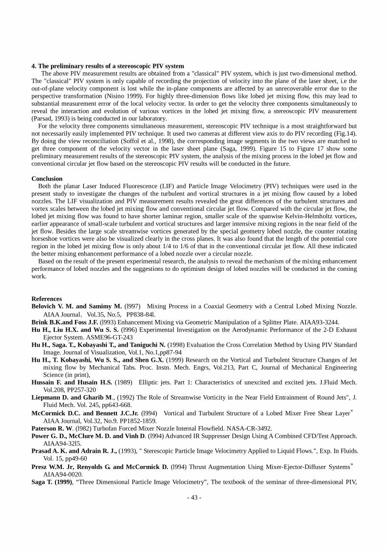
Figure 4 shows the LIF visualization and PIV measurement results of the lobed jet mixing flow in the axial slice passingthe lobe trough (Fig. 2(c)). Compared with the circular jet flow (Fig.3), the laminar region of the lobed jet mixing flow wasmuch shorter in this axial slice (Fig.4(a) and Fig.4(b)). The spanwise Kelvin-Helmholtz vortices were found to roll upalmost just from the trailing edge of the lobed nozzle. It can also be found that the size of these spanwise Kelvin-Helmholtzvortices were much smaller than that in the circular jet mixing flow (Fig.3(a)). Some small scale turbulent and vorticalstructures, which indicates the intensive mixing of the core jet flow with ambient flow, were found to appear in the flowfield from the downstream of X/D=1.0.
From the PIV measurement results (Fig.4(b) and Fig.4(c)) at this axial slice, it can also be seen that the lobed jet flowbegan to expend almost just from the exit of the lobed nozzle. The expand angle of the lobe jet mixing flow was found to bebigger than that in the conventional circular jet flow. The bigger high-turbulence-intensity regions (the regions of theturbulence intensity values bigger than 0.03m/s in the Fig.4(d) ) can be found to concentrate in the near field of the lobed jetmixing flow. The potential core region (the regions of turbulence-intensity value less than 0.02m/s in the Fig.4(d)) at thecentral of the lobed jet flow was much smaller and shorter than that in the circular jet flow(Fig.3(d)).
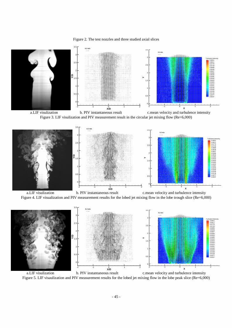
Figure 5 shows the LIF flow visualization and PIV measurement results in the lobed jet mixing flow at the axial slicepassing the lobe peak plane. The laminar region at the exit of the lobed nozzle in this axial slice was not a straight cylinderlike that in the circular jet (Fig.3(a)), and looked like a expansive cut-off cone along the downstream of the lobe structureinstead. Compared with that in the lobe trough slice, the laminar region in the lobe peak axial slice was a bit longer(X/D=0.5), but it was still much shorter than that in the circular jet mixing flow. This may be caused by the differentthickness of the boundary layer at the exit of the lobed nozzle (the work of the Brink et al.(1993) had verified that thethickness of the boundary layer at the lobe trough is smaller than that in the lobed peak), and the thicker boundary layer atthe lobe peak need a longer streamwise distance to roll-up the Kelvin-Helmholtz vortices (Hussain et al. 1989). In this axialslice, it can also be seen that small-scale turbulent and vortical structures were found to appear in the flow field from thedownstream of location X/D=1.0. Form the PIV time average results, it can be seen that most of the high-turbulence-intensity regions were concentrated at the near field of the lobed jet mixing flow. The potential core region at the central ofthe lobed jet mixing flow at this axial slice is also much smaller and shorter than that in circular jet mixing flow.
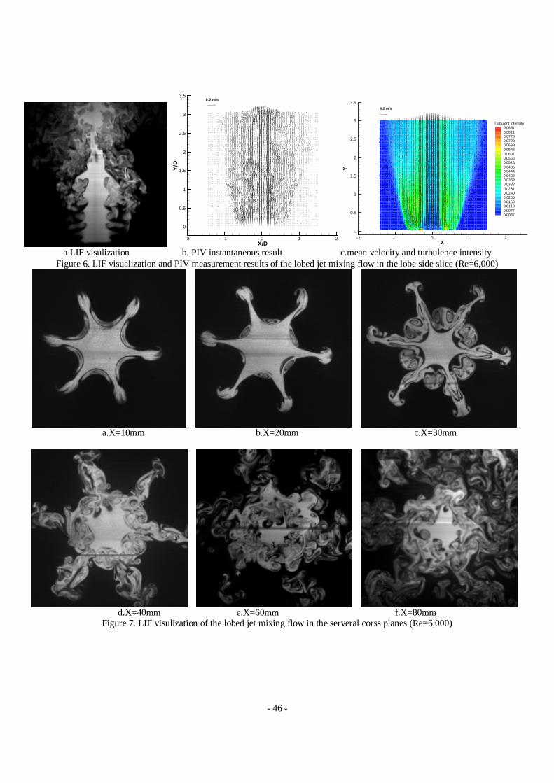
Figure 6 gives the LIF flow visualization and PIV measurement results of the lobed jet mixing flow in the axial slicepassing the lobe side plane (Fig.2(c)). In this axial slice, some streak flow structures can be seen clearly in the downstreamof the lobe structure trailing edge. These structures were the Kelvin-Helmholtz vortical tubes shed periodically from thelobe training edge, which was observed and called “normal vortex” by McCormick et al.(1994). At the downstream of thelocation X/D�1.0, small scale turbulent and vortical structures were found to appear in the flow field. As the same as thatin the lobe trough and lobe peak axial slices, most of the high intensity regions were found to concentrate at the near field ofthe lobed jet mixing flow. The potential core region at the central of the lobed jet mixing flow in this axial slice was alsomuch smaller and shorter than that in the circular jet.
2. In the cross planesFigure 7 shows the LIF flow visualization results of the lobed jet mixing flow in six cross planes. At the downstream
- 42 -
locations of X�l0mm (X/D=0.25, Fig.7(a)) and X�20mm (X/D=0.50, Fig.7(b)), the existence of the streamwise vorticesin the form of 6 petal “mushrooms” can be seen clearly in the lobed jet mixing flow. The spanwise Kelvin-Helmholtzvortices rolling up at the lobe trough were found to be as six crescents at these cross sections. As the streamwise distanceincreasing, the “mushrooms” grew up, which indicated the intensification of the streamwise vortices generated by lobednozzle.
As the streamwise vortices distance increased to X�30mm (X/D=0.75, Fig.7(c)), the streamwise vortices generated bythe lobed nozzle in the form of “mushrooms” structure keep on intensification. Six new counter-rotating streamwise vortexpairs can also be found in the flow field at six lobe troughs. Although the existence of the horseshoe structures at the lobetrough had been conjectured by Paterson (1982) about twenty years ago, this is the best known visualization result andprovides unquestionable evidence of their existence.
At the location of X=40mm (X/D=1.0, Fig. 7(d)), some small scale turbulent and vortical structures began to appear inthe flow due to the intensive mixing of the core jet flow with ambient flows. This verified the LIF visualization results of inthe axial slices which shown on the figure 4(a), Fig.5(a) and Fig. 6(a). The interaction between the streamwise vortices andKelvin-Helmholtz vortices made adjacent “mushrooms” merging with each other, which indicated the process that thestreamwise vortices deform the Kelvin-Helmholtz vortical tube into pinch-off structures suggested by McCormick etal.(1994).
At the location of X�60mm (X/D=1.5, Fig.7(e)) and X�80mm (X/D=2.0, Fig.7(f)), the “mushroom” shape structuresalmost disappeared in the flow field due to the intensive mixing between the core jet flow and ambient flows. The flow filedwas almost fully filled with small-scale turbulent and vortical structures.
While for the circular jet flow at the same Reynolds number level, the jet flow is still in this laminar region at the locationof X=40mm (X/D=1.0, Fig.8(a)). The spanwise Kelvin-Helmholtz vortices was found to begin to roll up at the location ofX=80mm (X/D=2.0, Fig. 8(b)). At the downstream of X=80mm (X/D=2.0, Fig. 8(b)), some streamwise vortices due to theazimuth instability (Liepmann et al.) were found to appear in the flow field. However, neither small-scale turbulentstructures nor small-scale vortical structures can be found at the cross planes of these locations for the circular jet flow.
Figure 9 to Figure 12 show the PIV measurement results at four typical cross planes of the lobed jet mixing flow, whichinclude instantaneous velocity fields, mean velocity fields, turbulent intensity distributions and mean streamwise vorticitydistributions. The large scale streamwise vortices generated by the special geometry of the lobe nozzle can be seen clearly atthe cross plane of X= 20mm (X/D=0.5, Fig.9). The intensive mixing regions (the high turbulence intensity regions in thewere found to be in the same configuration as the trailing edge of the lobed nozzle. Since the large scale streamwise vorticesgenerated by the lobed nozzle are steady vortices, they can be identified clearly in the PIV time average results (meanvelocity field and mean streamwise vorticity distribution).
As the streamwsie distance increase to 40mm (X/D=1.0, Fig. 10), the instantaneous velocity field was found to be moreturbulent than that in the X/D=20 cross plane (Fig 9A), However, the geometry of the lobed nozzle still can be identifiedfrom the velocity field. As the same as LIF visualization results, the smaller scale streamwise horseshoe vortical structurescan also be seen from the mean velocity field and mean streamwise vorticity field besides the six large scale vortices pairsgenerated by the lobed nozzle. The intensive mixing regions were found to expand outward and inward from the turbulenceintensity distribution.
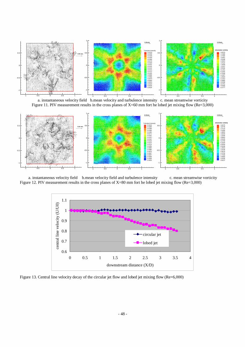
As the streamwise downstream increasing to X�60mm (X/D=1.5, Fig.11) and X�80mm (X/D=2.0, Fig.12), theinstantaneous velocity fields became much more turbulent, which indicate the more intensive mixing occurring in thesesection. The geometrical configuration of the lobed nozzle almost can not be identified from the instantaneous velocityfields. The large scale streamwise vortices generated by the lobed nozzle were found to break into much smaller vortices,and the vorticity of the streamwise vortices was also found to be decayed a lot due to the mixing of the core jet flow withambient flows. The intensive mixing regions expended much more seriously at these locations, which almost filled thestudied window fully.
3. Central line velocity decayIn order to give a more quantitative comparison of the mixing characteristics in the lobed jet mixing flow with
conventional circular jet flow, the central line velocity decay in the conventional circular jet and lobed jet mixing flow weregiven on the Fig.13. From the figure it can be seen that, the central line velocity of the circular jet flow almost keeps inconstant in the studied region. Previous research had shown that the length of potential core region in the conventionalcircular jet flow also ranges about 4-6 times of the circular nozzle exit diameter. While, for the lobed jet flow, the centralline velocity was found to begin to decay in the downstream of location Y/D=1.0. This means that the length of the potentialcore region in the lobed jet flow is just about 1/4 to 1/6 of the conventional circular jet flow, which also indicated the bettermixing enhancement performance of the lobed nozzle quantitatively
- 43 -
4. The preliminary results of a stereoscopic PIV systemThe above PIV measurement results are obtained from a "classical" PIV system, which is just two-dimensional method.
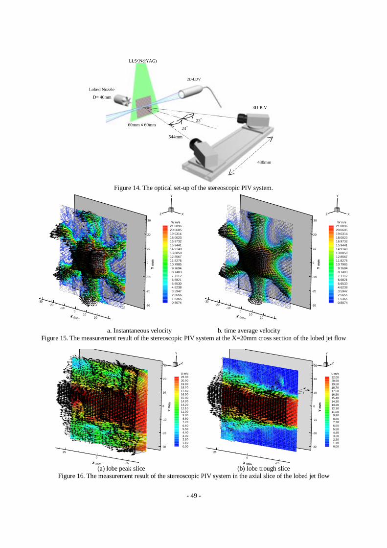
The "classical" PIV system is only capable of recording the projection of velocity into the plane of the laser sheet, i.e theout-of-plane velocity component is lost while the in-plane components are affected by an unrecoverable error due to theperspective transformation (Nisino 1999). For highly three-dimension flows like lobed jet mixing flow, this may lead tosubstantial measurement error of the local velocity vector. In order to get the velocity three components simultaneously toreveal the interaction and evolution of various vortices in the lobed jet mixing flow, a stereoscopic PIV measurement(Parsad, 1993) is being conducted in our laboratory.
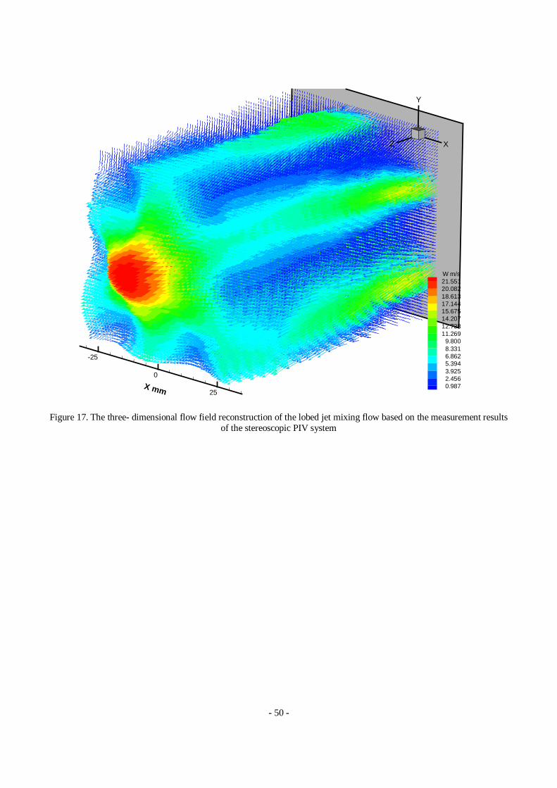
For the velocity three components simultaneous measurement, stereoscopic PIV technique is a most straightforward butnot necessarily easily implemented PIV technique. It used two cameras at different view axis to do PIV recording (Fig.14).By doing the view reconciliation (Soffol et al., 1998), the corresponding image segments in the two views are matched toget three component of the velocity vector in the laser sheet plane (Saga, 1999). Figure 15 to Figure 17 show somepreliminary measurement results of the stereoscopic PIV system, the analysis of the mixing process in the lobed jet flow andconventional circular jet flow based on the stereoscopic PIV results will be conducted in the future.
ConclusionBoth the planar Laser Induced Fluorescence (LIF) and Particle Image Velocimetry (PIV) techniques were used in the
present study to investigate the changes of the turbulent and vortical structures in a jet mixing flow caused by a lobednozzles. The LIF visualization and PIV measurement results revealed the great differences of the turbulent structures andvortex scales between the lobed jet mixing flow and conventional circular jet flow. Compared with the circular jet flow, thelobed jet mixing flow was found to have shorter laminar region, smaller scale of the spanwise Kelvin-Helmholtz vortices,earlier appearance of small-scale turbulent and vortical structures and larger intensive mixing regions in the near field of thejet flow. Besides the large scale streamwise vortices generated by the special geometry lobed nozzle, the counter rotatinghorseshoe vortices were also be visualized clearly in the cross planes. It was also found that the length of the potential coreregion in the lobed jet mixing flow is only about 1/4 to 1/6 of that in the conventional circular jet flow. All these indicatedthe better mixing enhancement performance of a lobed nozzle over a circular nozzle.
Based on the result of the present experimental research, the analysis to reveal the mechanism of the mixing enhancementperformance of lobed nozzles and the suggestions to do optimism design of lobed nozzles will be conducted in the comingwork.
ReferencesBelovich V. M. and Samimy M. (l997) Mixing Process in a Coaxial Geometry with a Central Lobed Mixing Nozzle.
AIAA Journal�Vol.35, No.5�PP838-84l.Brink B.K.and Foss J.F. (l993) Enhancement Mixing via Geometric Manipulation of a Splitter Plate. AIAA93-3244.Hu H., Liu H.X. and Wu S. S. (l996) Experimental Investigation on the Aerodynamic Performance of the 2-D Exhaust
Ejector System. ASME96-GT-243Hu H., Saga. T., Kobayashi T., and Taniguchi N.(1998) Evaluation the Cross Correlation Method by Using PIV Standard
Image. Journal of Visualization, Vol.1, No.1,pp87-94Hu H., T. Kobayashi, Wu S. S., and Shen G.X.(1999) Research on the Vortical and Turbulent Structure Changes of Jet
mixing flow by Mechanical Tabs. Proc. Instn. Mech. Engrs, Vol.213, Part C, Journal of Mechanical EngineeringScience (in print),
Hussain F. and Husain H.S.(1989) Elliptic jets. Part 1: Characteristics of unexcited and excited jets. J.Fluid Mech.Vol.208, PP257-320
Liepmann D. and Gharib M ., (1992) The Role of Streamwise Vorticity in the Near Field Entrainment of Round Jets", J.Fluid Mech. Vol. 245, pp643-668.
McCormick D.C. and Bennett J.C.Jr. (l994) Vortical and Turbulent Structure of a Lobed Mixer Free Shear Layer�
AIAA Journal, Vol.32, No.9. PP1852-1859.Paterson R. W. (l982) Turbofan Forced Mixer Nozzle Internal Flowfield.NASA-CR-3492.Power G. D., McClure M. D. and Vinh D. (l994) Advanced IR Suppresser Design Using A Combined CFD/Test Approach.
AIAA94-32l5.Prasad A. K. and Adrain R. J., (1993), " Sterescopic Particle Image Velocimetry Applied to Liquid Flows.", Exp. In Fluids.
Vol. 15, pp49-60Presz W.M. Jr, Renyolds G. and McCormick D. (l994) Thrust Augmentation Using Mixer-Ejector-Diffuser Systems�
AIAA94-0020.Saga T. (1999), “Three Dimensional Particle Image Velocimetry”, The textbook of the seminar of three-dimensional PIV,
- 44 -
VSJ-PIV-S2. (ISBN4-906497-21-9), pp41-61, Yokohama, JapanSmith L.L, Majamak A.J., Lam I.T. Delabroy O.,Karagozian A.R., Marble F.E. and Smith, O. I. , (l997) Mixing
Enhancement in a Lobed Injector. Phys. Fluids, Vol.9�No.3�PP667-678Soloff, S. M., Adrian R. J. and Liu Z. C., (1997), “Distortion Compensation for Generalized Stereoscopic Particle
Imaging Velocoimetry”, Measurement of Science and Technology, Vol.8, pp1441-1454Tillman T.G. and Presz W. M. Jr , (l993) Thrust Characteristics of a Supersonic Mixing Ejector. AIAA93-4345Willert C. E. and Gharib M. (l99l) Digital Particle Image Velocimetry. Exp. In Fluids, Vol. l0�PPl8l-l993.Westerweel, J.(1994) Efficient Detection of Spurious Vectors in Particle Image Velocimetry Data. Exp. In Fluids, Vol.16,
pp236-247
tested nozzle
jet supply tankpump
flow meter
CCD camera
Image process
system
Host computermonitor
optical system
YAG
laser
water tankLaser sheet
Optical filter
mixing region
comb structure
CCD camera
for LIF
for PIV
Figure 1. The schematic of the experimental set-up
Z
Y
Z
X
a. circular nozzle
b. lobed nozzle
c. three studied axial slices
outer penetration angle
inner penetrationangle
lobe heigth
lobe trough slicelobe peak slice
lobe side slice
lobe widthW= 6mm
220
140
H=15mm
- 45 -
Figure 2. The test nozzles and three studied axial slices
a.LIF visulization b. PIV instantaneous result c.mean velocity and turbulence intensityFigure 3. LIF visulization and PIV measurement result in the circular jet mixing flow (Re=6,000)
a.LIF visulization b. PIV instantaneous result c.mean velocity and turbulence intensityFigure 4. LIF visualization and PIV measurement results for the lobed jet mixing flow in the lobe trough slice (Re=6,000)
a.LIF visulization b. PIV instantaneous result c.mean velocity and turbulence intensityFigure 5. LIF visaulization and PIV measurement results for the lobed jet mixing flow in the lobe peak slice (Re=6,000)
a.LIF visulization b. PIV instantaneous result c.mean velocity and turbulence intensityFigure 6. LIF visualization and PIV measurement results of the lobed jet mixing flow in the lobe side slice (Re=6,000)
a.X=10mm b.X=20mm c.X=30mm
d.X=40mm e.X=60mm f.X=80mmFigure 7. LIF visulization of the lobed jet mixing flow in the serveral corss planes (Re=6,000)
- 47 -
a.X=40mm b.X=80mm b.X=120mmFigure 8. LIF visulization of the circular jet mixing flow in the serveral corss planes (Re=6,000)
a. instantaneous velocity field b.mean velocity and turbulence intensity c. mean streamwise vorticityFigure 9. PIV measurement results in the cross planes of X=20 mm fort he lobed jet mixing flow (Re=3,000)
a. instantaneous velocity field b.mean velocity and turbulence intensity d. mean streamwise vorticityFigure 10. PIV measurement results in the cross planes of X=40 mm fort he lobed jet mixing flow (Re=3,000)
a. instantaneous velocity field b.mean velocity and turbulence intensity c. mean streamwise vorticityFigure 11. PIV measurement results in the cross planes of X=60 mm fort he lobed jet mixing flow (Re=3,000)
a. instantaneous velocity field b.mean velocity field and turbulence intensity c. mean streamwise vorticityFigure 12. PIV measurement results in the cross planes of X=80 mm fort he lobed jet mixing flow (Re=3,000)
0.6
0.7
0.8
0.9
1
1.1
0 0.5 1 1.5 2 2.5 3 3.5 4
downstream distance (X/D)
cent
rall
ine
velo
city
(U/U
0)
circular jet
lobed jet
Figure 13. Central line velocity decay of the circular jet flow and lobed jet mixing flow (Re=6,000)
- 49 -
Figure 14. The optical set-up of the stereoscopic PIV system.
-30-20
-100
1020X mm
-30
-20
-10
0
10
20
30
Ym
m
X
Y
Z
W m/s21.089620.060519.031418.002316.973215.944114.914913.885812.856711.827610.7985
a. Instantaneous velocity b. time average velocityFigure 15. The measurement result of the stereoscopic PIV system at the X=20mm cross section of the lobed jet flow
-25
0
25
X mm
-30
-20
-10
0
10
20
30
Ym
m
X
Y
Z
U m/s22.0020.9019.8018.7017.6016.5015.4014.3013.2012.1011.00
9.908.807.706.605.504.403.302.201.100.00
-25
0
25
X mm
-30
-20
-10
0
10
20
30
Ym
m
X
Y
Z
U m/s22.0020.9019.8018.7017.6016.5015.4014.3013.2012.1011.00
9.908.807.706.605.504.403.302.201.100.00
(a) lobe peak slice (b) lobe trough sliceFigure 16. The measurement result of the stereoscopic PIV system in the axial slice of the lobed jet flow
544mm
430mm
LLS�Nd:YAG)
Lobed Nozzle
D= 40mm
3D-PIV
2D-LDV
23�
23�60mm�60mm
- 50 -
-25
0
25X mm
X
Y
Z
W m/s21.55120.08218.61317.14415.67514.20712.73811.269
9.8008.3316.8625.3943.9252.4560.987
Figure 17. The three- dimensional flow field reconstruction of the lobed jet mixing flow based on the measurement resultsof the stereoscopic PIV system