Page 1
Analysis and Optimization of turning operation : Taguchi and Principal Component
Analysis Approach 2013
Mechanical Engineering Department
Sikkim Manipal Institute of Technology Page 1
CHAPTER 1
INTRODUCTION
Metal cutting is one of the eminent and most commonly used manufacturing processes in any
metal processing or business industries. By machining processes or manufacturing operations,
attempts are made to make a particular product in several steps as of required dimensions and
shapes to assure the quality of machining products for the intended applications made for. The
step-by-step machining is done on the material to diminish the machining costs thereby
enhancing the machining effectiveness. Every manufacturing industry aims at producing a large
number of products within comparatively lesser time. It has long been determined that conditions
during cutting, such as feed rate, cutting speed and depth of cut, should be selected to optimize
the economics of machining operations, as assessed by productivity, total manufacturing cost per
component or some other convenient criterion. The optimization of cutting parameters during
machining is a toilsome task as it involves a number of aspects such as knowledge of machining,
empirical equations of tool life, cutting forces, power consumed, machining surface finish etc.
All these aspects should be studied during machining optimization to develop an effective
optimization criterion. Manufacturing industries have long relied on the skill and experience of
shop-floor machine-tool operators for optimal selection of cut-ting conditions and cutting tools.
1.1 LATHE
The lathe is basically a machine tool that removes unwanted material from a rotating
workpiece in the form of chips with the aid of a tool which is traversed across the work and can
be fed deep in work. The tool should be harder than the workpiece and must be held securely and
rigidly on the machine. Basically, the lathe is used to produce cylindrical surfaces and plain
surfaces at right angles to the axis of rotation. A lathe can also produce tapers. The workpiece is
either clamped in the chuck or between the centers.
Page 2
Analysis and Optimization of turning operation : Taguchi and Principal Component
Analysis Approach 2013
Mechanical Engineering Department
Sikkim Manipal Institute of Technology Page 2
1.2 SPECIFICATIONS OF LATHE
Generally, a lathe is designated by:
a. Height of centre measured above the lathe bed.
b. Maximum diameter or swing that can be rotated.
c. Shipping dimensions: LENGTH * BREADTH * HEIGHT * WIDTH * WEIGHT.
d. Maximum length of the job that can be held between the centers.
e. Spindle speed range.
f. Type of bed: It can be straight or gap bed.
g. Horse power of the driving motor.
1.3 CLASSIFICATION OF LATHES
The various types of lathes are as under:
a. Speed lathe: It is the simplest of all the lathes. Speed lathes can run at high speeds and is
generally used for turning woods, metals, spinning and polishing.
b. Engine lathe: This lathe derives its name from the early lathes that were driven by steam
engines and is the most important member of the lathe family. It’s also called centre
lathe and is the most widely used lathe across the globe.
c. Tool room lathe: The tool room lathe is basically similar in appearance to the centre
lathe but is built more precisely and accurately and has a wide range of speeds and is
equipped with many extra attachments and accessories and is used commonly for
precision works on tools, jigs, fixtures etc.
Page 3
Analysis and Optimization of turning operation : Taguchi and Principal Component
Analysis Approach 2013
Mechanical Engineering Department
Sikkim Manipal Institute of Technology Page 3
d. Bench lathe: Bench lathe is a small lathe mounted on a bench and performs all the
operations of an engine lathe. It’s basically used for small precision works and the only
difference is its size.
e. Capstan and Turret lathe: In this type of lathe, the tailstock is altered by a hexagonal
turret, on which multiple tools can be fitted and fed into the workpiece in proper
sequence. A number of identic jobs can be produced in minimum time, using this type of
lathe.
f. Special purpose lathe: These types of lathes are specifically designed to manufacture
unique parts. Some of the examples of these types of lathes are GAP LATHE, OIL
COUNTRY LATHEand WHEEL LATHE etc.
g. CNC lathe: Computer numerical controlled (CNC) lathes are rapidly replacing the older
production lathes (multispindle, etc.) due to their ease of setting, operation, repeatability
and accuracy. They are designed to use modern carbide tooling and fully use modern
processes. The part may be designed and the tool paths programmed by the CAD/CAM
process or manually by the programmer and the resulting file uploaded to the machine,
and once set and trialled the machine will continue to turn out parts under the occasional
supervision of an operator. The machine is controlled electronically via a computer menu
style interface; the program may be modified and displayed at the machine, along with a
simulated view of the process. The setter/operator needs a high level of skill to perform
the process, however the knowledge base is broader compared to the older production
machines where intimate knowledge of each machine was considered essential. These
machines are often set and operated by the same person, where the operator will
supervise a small number of machines (cell).
Page 4
Analysis and Optimization of turning operation : Taguchi and Principal Component
Analysis Approach 2013
Mechanical Engineering Department
Sikkim Manipal Institute of Technology Page 4
1.4 COMPONENTS OF LATHE
a. BED: The lathe bed constitutes the base of the machine. It must be tough enough to resist
deflection in any direction under load.It is made of cast iron or alloy steel.
It comprises flat or inverted V-shaped inner or outer guideways to guide the carriage
headstock and tailstock. The headstock and tailstock are situated at the either end of the
bed and the carriage lies over the lathe bed and slides over it.
b. HEAD STOCK: It is fixed at the left-hand –side of the lathe bed on the inner
guideways. It supports the spindle which is driven through the gear-box housed within
the headstock. Gear-box provides a wide range of speed of the spindle. The spindle is
hollow so that the long bars may be fed through it for continuous production. A live
centre, a face-plate, collector or a chuck can be fitted to a spindle nose to hold and drive
the work.
c. TAILSTOCK: It is located on the inner guideways at the right-hand-side of the lathe. It
basically has two main functions:
I. To support the free end of the workpiece when machined between the centers.
II. To hold tools for various operations such as drilling, tapping and reaming.
The body of the tailstock can be adjusted along the guideways by sliding it to the required
position and can be clamped by bolt and plate. It can be also offset for cutting a small
angle taper.
d. GUIDEWAYS: They may be V or flat shaped surface on which the carriage and
tailstock are moved left to right. Each has its separate pair of ways; often one flat surface
for stability and one V way for guidance in a perfectly straight line.
e. CARRIAGE: The carriage of the lathe has swivel parts that support, move and control
the cutting tool. It comprises the following parts:
Page 5
Analysis and Optimization of turning operation : Taguchi and Principal Component
Analysis Approach 2013
Mechanical Engineering Department
Sikkim Manipal Institute of Technology Page 5
I. Saddle: It is an H shaped casting that fits over the bed and slides along the
guideways. It carries the cross-slide and the tool post.
II. Cross-slide: The cross-slide carries the compound rest and tool post. It is used to give
depth of cut.
III. Compound rest: It is fitted on the top of a cross-slide and is used to support the
cutting tool. It can be moved in and out by its hand-wheel for facing or for setting the
depth of cut. It can also be rotated and fed by its hand-wheel at any angle.
IV. Tool post: It is mounted on the compound rest to hold the tool and enable it to be
adjusted to a convenient working position.
It can be of several types:
i. Single screw tool post
ii. Four way tool post
iii. Quick change tool post
V. Apron: The apron is fastened to the saddle and hangs over the front of the bed It
contains the gears, clutches for transmitting motion from feed rod to carriage and also
has split nut which engages with engages lead screw while thread cutting.
f. FEED ROD: It is a long shaft that has a key-way. The power is transmitted from the
lathe spindle to the apron gears through a feed rod via. a large number of gears. It is used
to move the carriage on cross-slide for turning, facing and all other operations except for
thread cutting.
g. LEAD SCREWS: It is powered by gears from the head stock and is used for providing
specifically accurate mechanized movements for cutting threads on the workpiece. In
some lathes, the lead screw performs the function of feed rod and there is no separate
feed rod.
Page 6
Analysis and Optimization of turning operation : Taguchi and Principal Component
Analysis Approach 2013
Mechanical Engineering Department
Sikkim Manipal Institute of Technology Page 6
1.5 LATHE ACCESSORIES
The devices used for holding and supporting the work and tool on the lathe are called lathe
accessories. Some of the lathe accessories are described as under:
a. CHUCKS: These are used for holding up the workpiece on lathe during the
machining operations. The workpiece of short length or large diameter or of irregular
shape, which cannot be held between the centers are held quickly and aptly in a
chuck. The chuck is attached to the lathe spindle by help of bolts with the back plate
screwed to the spindle nose. The different types of chucks are:
I. Three jaw universal chucks: It is also called self-centering chuck and all three
jaws move together in equal amounts to clamp the work. Therefore, the job is
automatically centered. The jaws have a series of teeth that mesh with the spiral
grooves on a circular plate with the chuck. This plate can be rotated by the
inserting a key in the square socket; resulting simultaneous radial motion of the
jaw.
II. Four jaw independent chucks: Each jaw is moved independently by rotating the
screw which meshes with the teeth cut on the underside of the jaw. They are used
for holding square, octagonal and large independent irregular components.
III. Combination chucks: They have the combination of both the above principles
and are provided with four jaws which can be operated either by scroll disc or
individually by separate screws.
IV. Magnetic chucks: These are used to hold the steel workpieces that are too thin to
be held in ordinary chucks. The faces of the chucks are magnetized with
permanent magnets contained within the chucks.
V. Collet chucks: They provide a quick means of holding the bar stock. Draw in
type collets are in common use. Their front portions are splitted which provide a
spring action and hence the grip.
VI. Hydraulic chucks: In these types of chucks, air or hydraulic pressure is used to
press the jaws against the job. The pressure is provided by a cylinder and piston
Page 7
Analysis and Optimization of turning operation : Taguchi and Principal Component
Analysis Approach 2013
Mechanical Engineering Department
Sikkim Manipal Institute of Technology Page 7
mechanism mounted on the back of the head stock and controlled by a valve by
the operator.
VII. Drill chucks: They are used for holding straight shank drills, taps and reamers for
drilling, tapping and reaming operations. They may be held either the head stock
or the tail stock. They have self centering jaw and are operated by keys.
b. FACE PLATES: They are large circular discs bored out and threaded to fit the nose
of the spindle. These have radial planes and T-slots for holding work by bolts and
clamps. They are used for holding the workpieces that cannot be held conveniently by
the chucks.
c. ANGLE PLATES: They are cast iron plates having two faces machined to make
them absolutely at right angles to each other. They are used for holding works in
conjunction with the face plates, when works cannot be directly mounted on the face
plates.
d. LATHE CENTRES: They are hardened steel devices used for holding and locating
the works to be machined. The centre fitted in head stock is live centre and in tail
stock is dead centre.
e. MANDRELS: They are used to hold and rotate hollow works between the centers.
They are made of high carbon steel and are slightly tapered. The mandrels are rotated
by lathe dogs and catch plates and the works are driven by friction.
f. STEADY RESTS: They comprise a cast iron frame made of two parts hinged
together on one side. The upper part can be swung back for inserting or removing the
jobs without disturbing the position of the steady rests. They can be clamped at any
position desired on the lathe bed guide ways. The main function of the steady rests is
to provide support to the long cylindrical works.
Page 8
Analysis and Optimization of turning operation : Taguchi and Principal Component
Analysis Approach 2013
Mechanical Engineering Department
Sikkim Manipal Institute of Technology Page 8
g. FOLLOWER RESTS: They consist of a C-shaped casting having two adjustable
jaws that support the work. They are attached to the saddle and move along the tool.
They prevent the job from springing away when cut is given.
1.5 LATHE ATTACHMENTS
a. GRINDING ATTACHMENT: It consists of a grinding wheel driven independently by
a small motor which is mounted on a cross slide. The job is held as usual in a chuck or
between centers and the rotating grinding wheel is fed against the job instead of the usual
cutting tool.
b. MILLING ATTACHMENT: It’s mounted on compound rest in the place of tool post. It
consists of a slide swivel vice. The base of swivel vice is graduated in degrees and can be
set at any required angle. This attachment is used for face milling, T-slot cutting, keyway
cutting etc.
c. STOPS: They are used on the carriage and cross slide to position them accurately. They
are used for repeated work. They save set up time and give more accurate results.
d. TAPER TURNING ATTACHMENTS: They are used for producing tapers on
cylinders. Similarly, various attachments like copying attachments, relieving
attachments etc. can be used on a lathe.
1.6 LATHE OPERATIONS
a. CENTERING: When the work is required to be turned between the centers or between
the chucks, a center, conical-shaped hole is to be provided at the end of the workpiece.
Centering is the operation of providing conical hole in the workpiece. The first step is to
Page 9
Analysis and Optimization of turning operation : Taguchi and Principal Component
Analysis Approach 2013
Mechanical Engineering Department
Sikkim Manipal Institute of Technology Page 9
locate the centre, after that a center punches and hammer is used to make deep
indentation. Center holes are produced by using a combined drill or a counter sink drill.
b. TURNING:It is the most commonly used operation on the lathe. In this method, excess
material is removed from the workpiece to produce conical or cylindrical surfaces. Fig
1:shows the basic turning mechanism.
Fig 1: Turning mechanism
The common methods of turning are:
I. PLAIN/STRAIGHT/SIMPLE TURNING: The workpiece is held in the spindle
and is rotated and the tool is fed in the direction parallel to the axis of rotation. The
surface generated is cylindrical.
II. TAPER TURNING:A conical surface by gradual reduction in the diameter of the
cylindrical job is produced by the operation. This can be obtained by the following
ways:
By Compound Feed: Longitudinal and cross feed is simultaneously engaged
which results in diagonal movement of the tool to produce a taper to the
workpiece. The direction of the resultant feed may be changed by varying the
rate of feeds by using the gears in the apron.
Page 10
Analysis and Optimization of turning operation : Taguchi and Principal Component
Analysis Approach 2013
Mechanical Engineering Department
Sikkim Manipal Institute of Technology Page 10
By Swivelling The Compound Rest: The work is held in the chuck or
between centers. The compound rest is swiveled to the desired angle (half of
taper angle) with respect to the work. The tool is fed manually by rotating the
hand-wheel of the compound rest.
Advantages:
Easy setting.
Steep tapers can be produced.
Both internal and external tapers can be made.
By Tailstock Setover Method: Principles of this method is to shift the axis of
rotation of the workpiece at an angle to the lathe axis and feeding the tool
parallel to the lathe axis. The angle at which the axis of rotation of the
workpiece is shifted is half the taper angle.
Advantages:
Good surface finish can be obtained.
Power feed can be obtained.
By Using Taper Turning Attachment: Taper turning attachment is provided
in few of the modern lathes. Its principle is to guide the tool in a straight path
set at an angle to the axis of rotation of the workpiece, while the work is being
held in the chuck.
Taper turning attachment is provided in the rear side of the lathe by means of
a bracket. It consists of swivel side which can be adjusted to the required
Page 11
Analysis and Optimization of turning operation : Taguchi and Principal Component
Analysis Approach 2013
Mechanical Engineering Department
Sikkim Manipal Institute of Technology Page 11
angle. A guide block sliding in this swivel slide is connected to the rear end of
the cross-slide. To turn the taper, swivel slide is set at half of the taper angle.
The cross-slide fixing screw is loosened. As the carriage travels in
longitudinal direction, the tool on cross-slide will follow straight angular path
set by the guide-block.
Advantages:
Good surface finish can be obtained.
The alignment of the lathe centers is not disturbed.
Lengthy tapers can be produced.
By Using A Form Tool: The broad hose tool having straight cutting edge is
set on tot the work at half taper angle and is fed straight into the work to
produce tapered surfaces.
c. FACING: It is an operation of generating flat surface at the ends of the workpiece. The
work is rotated and the tool is fed in a direction perpendicular to the axis of work. This is
used to cut the work of required length and to provide flat surface with axis of rotation of
the workpiece.
d. PARTING OFF:It is used for cutting away the required length from the bar stock, using
a flat nose tool, and feed is given in direction perpendicular to the axis of rotation.
e. GROOVING: It is the process of reducing the diameter of a workpiece over a narrow
surface. It is also known as recessing or necking operation. It is often at the end of a
thread or adjacent to a shoulder to ensure correct shape of mating.
f. KNURLING: It is the process of embossing diamond shaped pattern on the job. The
purpose of knurling is to provide:
Page 12
Analysis and Optimization of turning operation : Taguchi and Principal Component
Analysis Approach 2013
Mechanical Engineering Department
Sikkim Manipal Institute of Technology Page 12
Good grip; so that it doesn’t slip while operating.
Good appearance.
For raising the diameter to a small range for the assembly to get a press-fit.
g. CHAMFERING: It is the method of beveling the extreme ends of a workpiece. This is
done to remove the unwanted metal projection at the end and protect the end of the
workpiece from being damaged.
h. DRILLING: It is the process of making a hole in the workpiece. Before drilling, the
work should be faced and centered. The drill bit is held stationary in the tail-stock and the
drill is fed into the workpiece which is revolving in the chuck.
i. BORING: It is the operation of enlarging a drilled hole. The boring tool in held in the
tail-stock.
j. MILLING: It is the operation of removing metals by feeding the workpiece against the
rotary milling cutters. The milling cutters may be held by chuck or by attachment
mounted on the carriage.
k. GRINDING: Both internal and external surfaces may be ground by using grinding
attachment mounting on the cross-slide. Grinding should be done on a lathe only when no
other alternate machine is available, because for this lathe must be equipped with
reversing switches as the workpiece as the workpiece should rotate in opposite direction
to the grinding wheel.
Page 13
Analysis and Optimization of turning operation : Taguchi and Principal Component
Analysis Approach 2013
Mechanical Engineering Department
Sikkim Manipal Institute of Technology Page 13
l. THREAD CUTTING: It is one of the most important operations performed on the lathe.
The principle of thread cutting is to produce helical grooves on cylindrical or conical
surfaces by feeding the tool longitudinally when the job is revolved between the centers.
1.8 TOOL
A cutting tool is basically a metallic object which is used for removal of metal from a stock
part. In lathe, basically a single point cutting tool is employed for the removal of materials from
the workpiece in form of chips by feeding the tool to the job while the job is rotating.
1.9 TOOL NOMENCLETURE
a. FACE: Surface over which the chips flow.
b. FLANK: Surface below the cutting edge.
c. NOSE: The junction of side and end cutting angle.
d. SIDE CUTTING EDGE: It is formed by the intersection of flank and side flank. It does
the main cutting.
e. END CUTTING EDGE: It is the intersection of face and flank.
f. BACK RAKE ANGLE: It measures the downward slope of the top surface of the tool
from nose to the rear along the longitudinal axis.
i. It guides the direction of chip flow.
ii. It is called positive if it slopes downwards towards the shank. It is used to cut low
tensile strength ferrous materials.
Page 14
Analysis and Optimization of turning operation : Taguchi and Principal Component
Analysis Approach 2013
Mechanical Engineering Department
Sikkim Manipal Institute of Technology Page 14
iii. It is called negative if it slopes upwards towards the shank. It is used to cut high
tensile strength materials.
g. SIDE RAKE ANGLE: It measures the op surface of the tool to the side in the direction
perpendicular to the longitudinal axis.
h. SIDE RELIEF ANGLE: It is the angle made by the flank of the tool and a plane
perpendicular to base just under the side cutting edge. This allows the tool to be fed
sideways into the job; so that it can cut without rubbing.
i. END RELIEF ANGLE: It is a secondary relief angle between a plane perpendicular to
the base and end flank.
j. SIDE CUTTING EDGE ANGLE: It is the angle between the side cutting edge and the
longitudinal axis of the plane.
k. NOSE RADIUS: It is the curve formed by joining the side cutting and end cutting edges.
For heavier depths of cut and feeds and interrupted cuts, the nose is given a radius of
1.5mm for obtaining a higher tool life and better surface finish.
Note: Depth of cut should be more than nose radius.
Fig 2 gives a view of the basic tool nomenclature.
Page 15
Analysis and Optimization of turning operation : Taguchi and Principal Component
Analysis Approach 2013
Mechanical Engineering Department
Sikkim Manipal Institute of Technology Page 15
Fig 2: View of tool nomenclature
1.10 PROCEDURE FOR GRINDING HSS GENERAL PURPOSE LATHE TOOLS
First, begin by dressing the grinding wheel. Next, look up the optimum angles for the
workpiece material, then follow the steps described in the under given figure. Dip the tool in
coolant frequently to keep it away from annealing and over-heating, any discoloration on the bit
indicates it was drawn and was no longer hardened. Then, start over again from the beginning.
Tool bit angles are not critical and most tools will cut the material satisfactorily, but not
effectively.
Fig 3 describes the basic steps for sharpening of HSS tool bits.
Page 16
Analysis and Optimization of turning operation : Taguchi and Principal Component
Analysis Approach 2013
Mechanical Engineering Department
Sikkim Manipal Institute of Technology Page 16
Fig 3: Steps for sharpening of HSS tool bits
1.11 TOOL WEAR
During machining operation, the cutting edge of the tool gradually wears out and at
certain stage stops cutting.
The various types of tool wear are:
a. FLANK WEAR: Flat portion behind the cutting edge is worn out, which eliminates
some clearance and relief. It occurs while machining brittle materials like cast iron or
when feed is less than 0.15 mm/rev.
b. CRATER WEAR: It occurs on the rake face of the tool in the form of pit. It is formed at
some distance from the cutting edge. Crater wear is a temperature dependent
phenomenon.
c. SPALLING OR CRUMBLING: It takes place at the cutting edge while machining
extremely hard materials when cutting edges are not well supported.
Page 17
Analysis and Optimization of turning operation : Taguchi and Principal Component
Analysis Approach 2013
Mechanical Engineering Department
Sikkim Manipal Institute of Technology Page 17
d. LOSS OF HARDNESS: Under cutting conditions when the temperature and stresses are
high, plastic deformation may cause loss of hardness, and thus the cutting ability.
e. FRACTURE BY PROCESS OF MECHANICAL BREAKAGE: It takes place when
the cutting force is very large or by developing fatigue cracks under chatter conditions.
f. NOSE WEAR: This occurs after using the tool for a considerable amount of time. It
occurs only after crater wear occurs in unfavorable conditions like vibrations while
machining.
1.12SELECTION OF CUTTING SPEED AND FEED
a. WORKPIECE MATERIAL: Harder the material more is the force required and hence,
more is the wear of tools. Therefore, hard materials should be machined at decreased
cutting speed and smaller feed.
b. TOOL MATERIAL: An increase in cutting speed will result in more heat generation;
hence, more resistant tool should be used. They can also be used under heavier feeds.
c. TOOL GEOMETRY AND DIMENSION:A change in profile angles will
correspondingly change the force due to cutting action; as well as the condition for heat
transmission.
d. TYPE OF FINISH: Increased cutting speed and fine feed will give better surface finish.
Page 18
Analysis and Optimization of turning operation : Taguchi and Principal Component
Analysis Approach 2013
Mechanical Engineering Department
Sikkim Manipal Institute of Technology Page 18
e. SIZE OF CHIP CROSS-SECTION: It affects the forces due to cutting and
consequently amount of heat generated. Tool wear is more rapid. With increase in cutting
speed than with increase in the chip cross-section. The cross-section increase with the
increase in depth of cut.
f. RIGIDITY OF MACHINE: The operation performed should not produce vibration in
the machine.
g. TYPE OF COOLANT: Increased cutting speeds and increased feeds may be used with
the proper administration of coolants.
Page 19
Analysis and Optimization of turning operation : Taguchi and Principal Component
Analysis Approach 2013
Mechanical Engineering Department
Sikkim Manipal Institute of Technology Page 19
CHAPTER 2
LITERATUREREWIEW
Hasan et al. [1] in the year 2007 focused on the analysis of optimum cutting conditions to
get lowest surface roughness in turning SCM 440 alloy steel by Taguchi method. The challenge
of modern machining industries is mainly focused on the achievement of high quality, in terms
of workpiece dimensional accuracy, surface finish, high production rate, less wear on the cutting
tools, economy of machining in terms of cost saving and increase the performance of theproduct
with reduced environmental impact.
Krishankant et al. [2] in the year 2012 reports on an optimization of turning process by
the effects of machining parameters applying Taguchi methods to improve the quality of
manufactured goods, and engineering development of designs for studying variation. EN24 steel
is used as the work piece material for carrying out the experimentation to optimize the Material
Removal Rate.Taguchi orthogonal array is designed with three levels of turning parameters with
the help of software Minitab 15.Taguchi method stresses the importance of studying the response
variation using the signal–to–noise (S/N) ratio, resulting in minimization of quality characteristic
variation due to uncontrollable parameter.
Kivak et al.[3]in the year 2012 reports effect of deep cryogenic treatment and drilling
parameters on surface roughness and roundness error that were investigated in drilling of AISI
316 austenitic stainless steel with M35 HSS twist drills. In addition, optimal control factors for
the hole quality were determined by using Taguchi technique. Two cutting tools, cutting speeds
and feed rates were considered as control factors, and L8 orthogonal array was determined for
experimental trials. Multiple regression analysis was employed to derive the predictive equations
of the surface roughness and roundness error achieved via experimental design. Minimum
surface roughness and roundness error were obtained with treated drills at 14 m/min cutting
speed and 0.08 mm/rev feed rate. Confirmation experiments showed that Taguchi method
precisely optimized the drilling parameters in drilling of stainless steel.
Page 20
Analysis and Optimization of turning operation : Taguchi and Principal Component
Analysis Approach 2013
Mechanical Engineering Department
Sikkim Manipal Institute of Technology Page 20
Shivakoti et al. [4] in the year 2012 report the application of various optimization
techniques that are playing vital role which seeks identification of the best process parametric
condition for that particular manufacturing or metal removal process. In this research paper,
Genetic Algorithm (GA) has been applied for optimizing of machining parameters during turning
operation of mild steel using conventional lathe machines. The purpose of this paper is to find
the optimum parameters values for turning operations for maximizing the material removal rate.
The machining parameters that been consider in this paper are cutting speed, feed rate and
spindle speed. The Turbo C compiler is used to develop the GA simulation. GA can be used in
optimization problems such as scheduling, materials engineering, optimal control, and so forth.
Swamy[5]in the year 2012 obtained an optimal setting of turning parameters (Cutting
speed, Feed and Depthof Cut) which results in an optimal value of Surface Roughness while
machining Al 6351-T6 alloy with Uncoated Carbide Inserts. Several statistical modeling
techniques have been used to generate models including Genetic Algorithm, Response Surface
Methodology. In our study, an attempt has been made to generate a model to predict Surface
Roughness using Regression Technique. Also an attempt has been made to optimize the process
parameters using Taguchi Technique. S/N ratio and ANOVA analysis were also performed to
obtain significant factors influencing Surface Roughness.
Hasluck [6] in the year 1883 sharedpractical knowledge on the turning processes vividly.
The effects of spindle speed, cutting speed, rake angle, depth of cut, feed rate etc. on turning
processes is explained clearly and shown vividly by diagrams. Of all the mechanical arts, none
can claim a more important place than that of turning, and practice of this branch of mechanical
manipulation is capable of developing the highest skill and intelligence of the artificer.
Woolf [7] explained everything about the Taguchi method generously. The design of
experiments, the orthogonal arrays etc. are all being shown in a much easier and compatible way.
This book carries message that efficient experimental design helps to optimize the process and
determine factors that influence variability. It also teaches us that factorial designs are easy to
construct but can be impractically large and Taguchi and random designs often perform better
depending on size and assumptions.
Page 21
Analysis and Optimization of turning operation : Taguchi and Principal Component
Analysis Approach 2013
Mechanical Engineering Department
Sikkim Manipal Institute of Technology Page 21
Hagiwara [8] in the year 2005 studies that unlike straight turning, the effective cutting
conditions and tool geometry in contour turning operations are changing with changing work
piece profile. This causes a wide variation in machining performance such as chip flow and chip
breakability during the operation. This thesis presents a new methodology for optimizing the
machining performance, namely, chip breakability and surface roughness in contour finish
turning operations. In machining operations, chip control is one of the most important factors for
achieving good surface finish and part quality, operator safety, machine productivity, cost
efficiency, and tool sustainability.
Nalbant et al.[9]in the year 2006 studies that the Taguchi method is used to find the
optimal cutting parameters for surface roughness in turning. The orthogonal array, the signal-to-
noise ratio, and analysis of variance are employed to study the performance characteristics in
turning operations of AISI 1030 steel bars using TiN coated tools. Three cutting parameters
namely, insert radius, feed rate, and depth of cut, are optimized with considerations of surface
roughness. Experimental results are provided to illustrate the effectiveness of this approach.
Kshirsagar et al. [10] in the year 2012 studies that the Taguchi method is a statistical
approach to overcome the limitation of the factorial and fractional factorial experiments by
simplifying and standardizing the fractional factorial design. The objective of the current study is
to illustrate the procedures and strengths of the Taguchi method in Lathe facing operation. The
orthogonal array, the signal-to-noise ratio, and analysis of variance are employed to study the
performance characteristics in facing operation. Theoretical analysis has been performed to find
the critical parameters. Three cutting parameters namely, feed rate, depth of cut and spindle
speed, are the cutting parameters considered. An orthogonal array has been selected and
constructed according to the need of the experiment.
Experimental runs according to the orthogonal array will be conducted and surface roughness
will be measured. Accordingly, S/N ratio will be calculated to construct an ANOVA table. With
help of linear graphs, optimum parameter values will be obtained and confirmation experiments
have to be conducted.
Usman [11] in the year 2012 explains the effect of tool rake angles on tool life.The rake
angles of 00, 5
0, 10
0, 15
0, and 20
0 and a constant clearance (Relief angle) of 8
0 were used to turn
Page 22
Analysis and Optimization of turning operation : Taguchi and Principal Component
Analysis Approach 2013
Mechanical Engineering Department
Sikkim Manipal Institute of Technology Page 22
bright mild steel on the lathe machine, with a high speed steel of 18mm side as cutting tooland
soluble oil was used as coolant. This is all in order to explore the energy savings opportunities
during regrinding of tools, useful production time and energy is being wasted due to regrinding
or re-sharpening of tools when cutting tools got worn or blunt, selection of the best rake angle
which elongates tool life goes a long way in saving these time and energy. It was observed that,
the rake angle of 200 gave the longest tool life as well as the best surface finish and yielded
continuous chips formation.
Miroslav et al. [12]in the year 2012 proposed the optimization of cutting parameters
based on cutting force in tube turning of S235 G2T steel by coated carbide tool using Taguchi
method . Three cutting parameters, namely cutting speed, feed and depth of cut are optimized
with considerations of cutting force as performance characteristic. The effects of cutting
parameters on the cutting force components were experimentally investigated. As per Taguchi’s
orthogonal arrays, experimentation was conducted. Three cutting parameters with three levels
are arranged in L9 orthogonal array. The orthogonal array, measured values of cutting force
components, signal-to-noise ratios, and analysis of variance are employed in order to study the
cutting force. Based on this analysis the optimal cutting parameters settings were determined.
Chaudhari et al. [13]in the year 2009 studies that a single characteristic response
optimization model based on Taguchi Technique is developed to optimize process parameters,
such as speed, feed, depth of cut, and nose radius of single point cutting tool. Taguchi’s L9
orthogonal array is selected for experimental planning. The experimental result analysis showed
that the combination of higher levels of cutting speed, depth of cut and lower level of feed is
essential to achieve simultaneous maximization of material removal rate and minimization of
surface roughness. This paper also aims to determine parametric relationship and its effect on
surface finish.
Kirby.[14]in the year 2006 investigates the use of Taguchi Parameter Design for
optimizing surface roughness generated by a CNC turning Operation. This study utilizes a
standard orthogonal array for determining the optimum turning parameters, with an applied noise
factor. Controlled factors include spindle speed, feed rate, and depth of cut; and the noise factor
is slightly damaged jaws. The noise factor is included to increase the robustness and applicability
Page 23
Analysis and Optimization of turning operation : Taguchi and Principal Component
Analysis Approach 2013
Mechanical Engineering Department
Sikkim Manipal Institute of Technology Page 23
of this study. After experimentally turning sample workpieces using the selected orthogonal
array and parameters, this study produced a verified combination of controlled factors and a
predictive equation for determining surface roughness with a given set of parameters.
Gopalsamy et al.[15]in the year 2009 utilizes a standard orthogonal array for determining
the optimum turning parameters, with an applied noise factor. Controlled factors include spindle
speed, feed rate, and depth of cut; and the noise factor is slightly damaged jaws. The noise factor
is included to increase the robustness and applicability of this study. After experimentally turning
sample workpieces using the selected orthogonal array and parameters, this study produced a
verified combination of controlled factors and a predictive equation for determining surface
roughness with a given set of parameters.
Dubey et al. [16] in the year 2007 made a hybrid approach of Taguchi method (TM) and
principal component analysis (PCA) for multi-objective optimization (MOO) of pulsed Nd:YAG
laser beam cutting (LBC) of nickel-based superalloy (SUPERNI718) sheet to achieve better cut
qualities within existing resources. The three-quality characteristics kerf width, kerf deviation
(along the length of cut), and kerf taper have been considered for simultaneous optimization. The
input parameters considered are assist gas pressure, pulse width, pulse frequency, and cutting
speed. Initially, single-objective optimization has been performed using TM and then the signal-
to-noise (S/N) ratios obtained from TM have been further used in PCA for multi-objective
optimization. The results of MOO include the prediction of optimum input parameter level and
their relative significance on multiple quality characteristics (MQC). The responses at predicted
optimum parameter level are in good agreement with the results of confirmation experiments
conducted for verification tests.
So, after studying the above mentioned research papers, basically an attempt to design an
L9orthogonal array using TM and as per the design of the model, attempt has been taken to
perform nine experiments to find out the maximum MRR considering the process parameters viz.
Spindle Speed, Depth of Cut and Rake Angle.
Page 24
Analysis and Optimization of turning operation : Taguchi and Principal Component
Analysis Approach 2013
Mechanical Engineering Department
Sikkim Manipal Institute of Technology Page 24
CHAPTER 3
OBJECTIVE OF THE PROJECT
It can be very clearly seen from the review of past research that a lot of theoretical and
experimental works have been carried out for proper understanding of the basic process of
turning using a lathe and for identifying the actual process parameters setting to optimize turning
performance criteria.
Some researchers have applied the lathe for turning of difficult and intricate shapes. These
shapes can be easily and efficiently machined with CNC lathes. Due to recent advancement of
the computer numerical technology, various new types of X-Y-Z CNC controlled lathe machines
are available in the manufacturing industries. Some of the researchers have used the types of
lathes for their experiments. But these machines are very costly and their maintenance is much
complicated. So for the sake of low cost of production, an attempt has been made to optimize the
various cutting parameters viz. spindle speed, depth of cut and rake angle, using TM which is
one of the most commonly used optimization technique. Using the Taguchi optimization
technique, it was tried to seek out under which optimal conditions, the MRR will be maximum.
Later, the maximum value procured from the TM was compared with the value of optimum
MRR using PCA technique.
Therefore, the objectives can be defined as follows:
I. Experimental Design using Taguchi Method.
II. Calculation of various MRR’s and MT’s.
III. Analysis of Material Removal Rate.
IV. Development of regression equations of MRR and MT.
V. Comparison of experimental and regression predicted values for MRR.
VI. Single objective Optimization using Taguchi Method.
VII. Multi objective optimization using Principal Component Analysis.
Page 25
Analysis and Optimization of turning operation : Taguchi and Principal Component
Analysis Approach 2013
Mechanical Engineering Department
Sikkim Manipal Institute of Technology Page 25
CHAPTER4
EXPERIMENTAL PLANNING AND ANALYSIS OF
TURNINGOPERATION
4.1 EXPERIMENTAL PLANNING
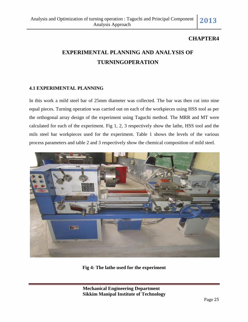
In this work a mild steel bar of 25mm diameter was collected. The bar was then cut into nine
equal pieces. Turning operation was carried out on each of the workpieces using HSS tool as per
the orthogonal array design of the experiment using Taguchi method. The MRR and MT were
calculated for each of the experiment. Fig 1, 2, 3 respectively show the lathe, HSS tool and the
mils steel bar workpieces used for the experiment. Table 1 shows the levels of the various
process parameters and table 2 and 3 respectively show the chemical composition of mild steel.
Fig 4: The lathe used for the experiment
Page 26
Analysis and Optimization of turning operation : Taguchi and Principal Component
Analysis Approach 2013
Mechanical Engineering Department
Sikkim Manipal Institute of Technology Page 26
Fig 5: The HSS tool used for the experiment
Fig 6: The workpieces used for the experiment
Table1:Levels of the various process parameters
Machining parameters Level 1 Level 2 Level 3
Spindle speed 200 300 450
Depth of cut 0.5 1.0 1.5
Rake angle 5 10 15
Page 27
Analysis and Optimization of turning operation : Taguchi and Principal Component
Analysis Approach 2013
Mechanical Engineering Department
Sikkim Manipal Institute of Technology Page 27
Table 2: Chemical composition of mild steel:
Elements Carbon
(C)
Manganese
(Mn)
Silicon
(Si)
Others
Percentage 0.25 0.4-0.7 0.1-0.5 Balance
Table 3: Chemical composition of HSS
Elements
Carbon
(C)
Chromium
(Cr)
Molybdenum
(Mo)
Tungsten
(W)
Vanadium
(V)
Cobalt
(Co)
Percentage
0.94 4.1 5.0 6.0 2.0 5.0
Fig 7: Chemical Composition of HSS
Carbon
Chromium
Molybdenum
Tungsten
Vanadium
Cobalt
Page 28
Analysis and Optimization of turning operation : Taguchi and Principal Component
Analysis Approach 2013
Mechanical Engineering Department
Sikkim Manipal Institute of Technology Page 28
4.2 FORMULAE OF VARIOUS CUTTING PARAMETERS WITH EXPLANATION
For machining operations, it is necessary to have relative motion between the workpiece
and the tool, e.g. for drilling operation, we may rotate the drill bit or the workpiece and besides
this, we need to press the drill against the workpiece so that it penetrates the workpiece.
First motion (i.e. rotation of drill bit or workpiece) is called primary or cutting motion
and the second one is called feed motion.
I. SPINDLE SPEED: It is the speed at which the spindle attached to the chuck in the
head stock rotates.
It is expressed in RPM
Spindle speed is given by the relation
N=v × 1000/π d (1)
Where,
d = Diameter of the job in mm.
N= Spindle speed in RPM
v = Cutting speed in mm/min
II. FEED: It refers to the amount of tool advancement per revolution of the job parallel
to the surface of the job. It enables the cutting process to be extended to the entire
surface of the job.
It is expressed in mm.
III. DEPTH OF CUT: It refers to the advancement of the tool in the tool in a direction
perpendicular to the surface being machined.
Depth of cut= (d1-d2)/2 (2)
Where,
d1= Diameter of uncut surface.
d2=Diameter of machined surface.
Page 29
Analysis and Optimization of turning operation : Taguchi and Principal Component
Analysis Approach 2013
Mechanical Engineering Department
Sikkim Manipal Institute of Technology Page 29
IV. MACHINING TIME: Machining time of lathe depends upon the speed, feed and
length of the job.
It is given by the relation
T= l/fN (3)
Where,
l = length of the job.
f = feed.
N= Spindle speed
V. MATERIAL REMOVAL RATE: It is the volume of metal removed per unit time.
It is expressed in mm3/min.
It is given by the relation
MRR= π×d×D×f×N (4)
Where,
d= diameter of the uncut job.
D= depth of cut.
f= feed
N= Spindle speed
4.3 DESIGN OF EXPERIMENT BASED ON TAGUCHI
The basic orthogonal array design of L9 Taguchi method is shown in Table 4.
Table 4: Orthogonal array L9 of Taguchi
Sl no. Parameter 1 Parameter 2 Parameter 3
1 1 1 1
2 1 2 2
3 1 3 3
4 2 1 2
5 2 2 3
Page 30
Analysis and Optimization of turning operation : Taguchi and Principal Component
Analysis Approach 2013
Mechanical Engineering Department
Sikkim Manipal Institute of Technology Page 30
6 2 3 1
7 3 1 3
8 3 2 1
9 3 3 2
Table 5 shows the design of experiment on orthogonal array L9 of Taguchi method.
Table 5: Experimental Design based on Orthogonal array L9 of Taguchi
Sl no. Spindle Speed
(x1)(RPM)
Depth of Cut (x2)
(mm)
Rake Angle (x3)
(degrees)
1 200 0.5 5
2 200 1.0 10
3 200 1.5 15
4 300 0.5 10
5 300 1.0 15
6 300 1.5 5
7 450 0.5 15
8 450 1.0 5
9 450 1.5 10
4.4 EXPERIMENTAL RESULTS
After conducting the experiment on different test workpieces the under given results were
obtained as shown in Table 6.
Page 31
Analysis and Optimization of turning operation : Taguchi and Principal Component
Analysis Approach 2013
Mechanical Engineering Department
Sikkim Manipal Institute of Technology Page 31
Table 6: The different values achieved after performing the experiment
Sl no. Spindle Speed
(RPM)
x1
Depth of Cut
(mm)
x2
Rake Angle
(degrees)
x3
MRR
(mm3/min)
MT
(sec)
1 200 0.5 5 725.26 11.05
2 200 1.0 10 1806.18 6.46
3 200 1.5 15 2226.6 8.46
4 300 0.5 10 1142.75 5.48
5 300 1.0 15 1822.04 8.45
6 300 1.5 5 2261.95 8.35
7 450 0.5 15 1024.95 6.11
8 450 1.0 5 1555.09 8.02
9 450 1.5 10 2014.56 9.15
Page 32
Analysis and Optimization of turning operation : Taguchi and Principal Component
Analysis Approach 2013
Mechanical Engineering Department
Sikkim Manipal Institute of Technology Page 32
4.5 ANALYSIS OF MRR
Fig 8 shows the effect of machining parameters of MRR
Fig 8: Effect of machining parameters on MRR
I. Spindle speed: It is very clearly visible from the graph that MRR is maximum at 300
rpm. It is due to the fact that at 450 rpm the tool wears and machining is improper if
the supply of coolant is absent (as in this case).
II. Doc: From the graph is it noticeable that maximum MRR is achieved when the depth
of cut is the most (1.5mm as in this case).
III. Rake angle: From the graph it’s seen that maximum MRR is obtained when rake
angle is set to 15 .
4.6 REGRESSION ANALYSIS
The first necessary step for process parameter optimization in any metal cutting process
is to understand the principles governing the cutting processes by developing an explicit
mathematical model. Here, statistical regression technique has been used to model the equation
using Analysis of Variance (ANOVA). The objective consists of adjusting the parameters of a
Page 33
Analysis and Optimization of turning operation : Taguchi and Principal Component
Analysis Approach 2013
Mechanical Engineering Department
Sikkim Manipal Institute of Technology Page 33
model function to best fit a data set. A simple data set consists of n points (data pairs) (xi, yi) i =
1, ..., n, where xi is an independent variable and yi is a dependent variable whose value is found
by observation. The model function has the form f(x, β), where the m adjustable parameters are
held in the vector β. The goal is to find the parameter values for the model which "best" fits the
data. The least squares method finds its optimum when the sum, S, of squared residuals
S = ∑ i
2 (5)
is a minimum. A residual is defined as the difference between the actual value of the dependent
variable and the value predicted by the model.
ri = yi – f (xi , β) (6)
An example of a model is that of the straight line. Denoting the intercept as β0 and the slope as
β1, the model function is given by
f (x , β) = β0 + β1x (7)
A data point may consist of more than one independent variable. For an example, when fitting a
plane to a set of height measurements, the plane is a function of two independent variables, x and
z, say. In the most general case there may be one or more independent variables and one or more
dependent variables at each data point. The minimum of the sum of squares is found by setting
the gradient to zero. Since the model contains m parameters there are m gradient equations.
= 2∑ i
= 0, j = 1,…,m (8)
From equation (6) and (8), the gradient equation can be written as
-2∑
= 0, j = 1,…,m (9)
The gradient equations apply to all least squares problems. Each particular problem requires
particular expressions for the model and its partial derivatives. A regression model is a linear one
when the model comprises a linear combination of the parameters, i.e.
( ) ∑ (10)
Page 34
Analysis and Optimization of turning operation : Taguchi and Principal Component
Analysis Approach 2013
Mechanical Engineering Department
Sikkim Manipal Institute of Technology Page 34
Here the coefficients, , are functions of .
Letting
xij =
= (11)
In case the least square estimate (or estimator, in the context of a random sample),β is given by
= (XT
X)-1
XT
y (12)
The following regression equation has been developed based on the experimental results shown
in Table 6. This regression equation is achieved by feeding the experimental data to the statistical
Minitab software.
The regression equation is
MRR = - 1132 + 0.793 x1 + 1736 x2 + 273 x3 + 1.57 x1x2 - 125 x2x3 - 0.382 x1x3 (13)
R-Sq= 99.9%
MT = 18.8 - 0.0150 x1 - 4.27 x2 - 1.61 x3 - 0.0022 x1x2 + 0.772 x2x3+ 0.00224 x1x3 (14)
R-Sq = 74.9%
Here, x1, x2 and x3 correspond to the process parameters spindle speed, depth of cut and rake
angle in uncoded values.
Tables 7 and 8 respectively show model of various factors, interactions and outputs calculated
during the performance of experiment and Percentage error difference between the experimental
and regression predicted values of MRR.
Figures 9 and 10 respectively show plot of experimental and regression predicted values of
MRR against experiment number and plot of experimental and regression predicted values of
MRR against percentage error.
Page 35
Analysis and Optimization of turning operation : Taguchi and Principal Component
Analysis Approach 2013
Mechanical Engineering Department
Sikkim Manipal Institute of Technology Page 35
Table 7: Model of Various Factors, Interactions and Outputs Calculated During the
Performance of Experiment
Sl no. Spindle
Speed
(RPM)
x1
Depth
of Cut
(mm)
x2
Rake
Angle
(degrees)
x3
x1 x2 x2 x3 x1 x3 MRR
(mm3/min)
MT
(sec)
1 200 0.5 5 100 2.5 1000 725.26 11.05
2 200 1.0 10 200 10 2000 1806.18 6.46
3 200 1.5 15 300 22.5 3000 2226.6 8.46
4 300 0.5 10 150 5 3000 1142.75 5.48
5 300 1.0 15 300 15 4500 1822.04 8.45
6 300 1.5 5 450 7.5 1500 2261.95 8.35
7 450 0.5 15 225 7.5 6750 1024.95 6.11
8 450 1.0 5 450 5 2250 1555.09 8.02
9 450 1.5 10 675 15 4500 2014.56 9.15
Page 36
Analysis and Optimization of turning operation : Taguchi and Principal Component
Analysis Approach 2013
Mechanical Engineering Department
Sikkim Manipal Institute of Technology Page 36
Table 8: Percentage Error Difference Between the Experimental and Regression Predicted
Values of MRR
Average predicted error is 0.64 %
Sl. no Experimental Regression predicted %error
1 725.26 722.1 0.435
2 1806.18 1792.6 0.752
3 2226.6 2238.1 0.516
4 1142.75 1168.4 2.24
5 1822.04 1813.9 0.447
6 2261.95 2270.9 0.396
7 1024.95 1025.1 0.014
8 1555.09 1547.85 0.465
9 2014.56 2024.6 0.498
Page 37
Analysis and Optimization of turning operation : Taguchi and Principal Component
Analysis Approach 2013
Mechanical Engineering Department
Sikkim Manipal Institute of Technology Page 37
Fig 9: Plot of experimental and regression predicted values of MRR against experiment
number
Page 38
Analysis and Optimization of turning operation : Taguchi and Principal Component
Analysis Approach 2013
Mechanical Engineering Department
Sikkim Manipal Institute of Technology Page 38
Fig 10: Plot of experimental and regression predicted values of MRR against percentage
error
4.7ANALYSIS OF VARIANCE (ANOVA)
To test whether the data predicted by regression model is well fitted or not, analysis of
variance (ANOVA) has been carried out. The ANOVA results for MRR model have been shown
in table given under. From the table, it is clear that the calculated F-values for the MRR against
Spindle Speed, Depth of Cut and Rake Angle are 0.09, 38.50 and 0.07 respectively which are in
the acceptable ranges. Also, p-values of the source of regression model are 0.913, 0.000 and
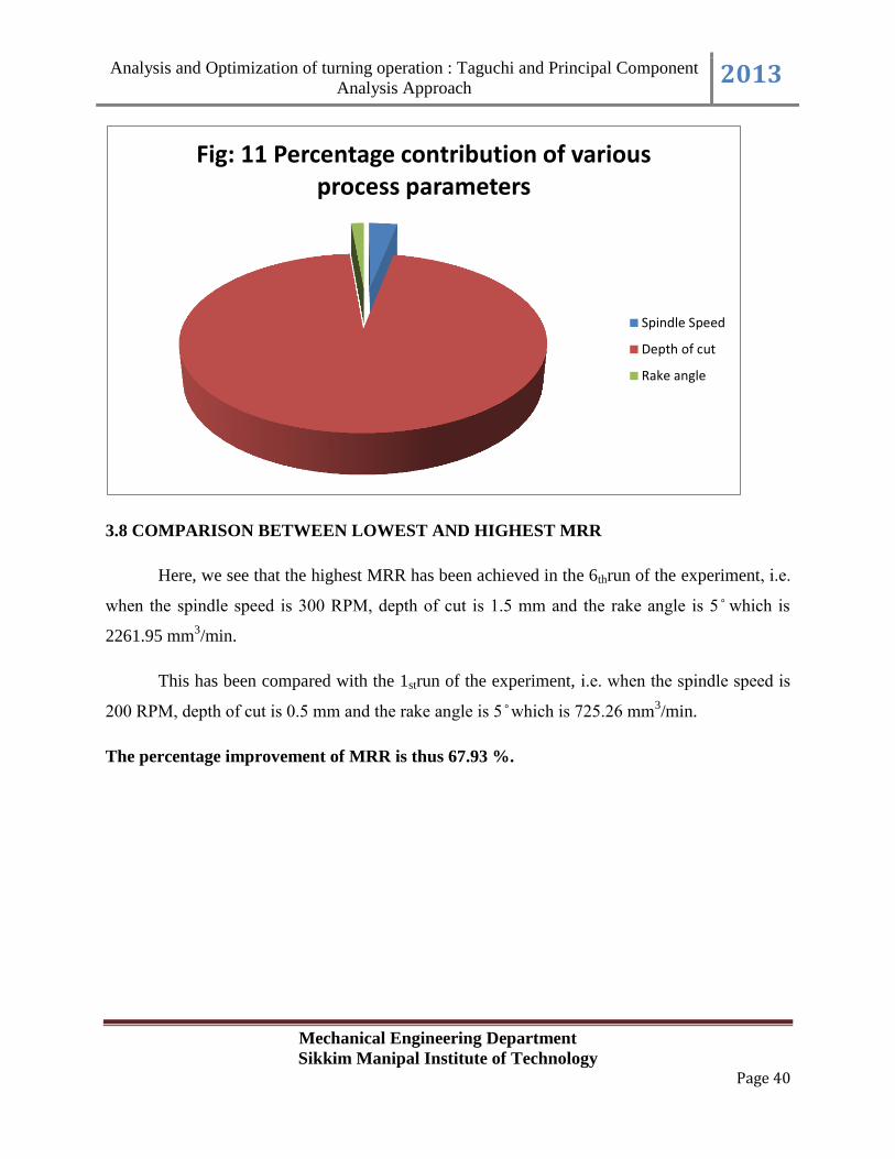
0.936 respectively. Table 9 and figure 11 shows the percentage contribution of various process
parameters.
Page 39
Analysis and Optimization of turning operation : Taguchi and Principal Component
Analysis Approach 2013
Mechanical Engineering Department
Sikkim Manipal Institute of Technology Page 39
Table 9: Percentage contribution chart
Source Degree of
Freedom
Sum of
Squares
Mean Sum
of Squares
F-value P-value %
Contribution
Spindle
Speed
2 71777 35889 0.09 0.913 3.06
Error 6 2326072 387679
Total 8 2397849
Depth of
Cut
2 2224529 1112264 38.50 0.000 94.71
Error 6 173320 28887
Total 8 2397849
Rake
Angle
2 52421 26211 0.07 0.936
2.24
Error 6 2345428 390905
Total 8 2397849
Page 40
Analysis and Optimization of turning operation : Taguchi and Principal Component
Analysis Approach 2013
Mechanical Engineering Department
Sikkim Manipal Institute of Technology Page 40
3.8 COMPARISON BETWEEN LOWEST AND HIGHEST MRR
Here, we see that the highest MRR has been achieved in the 6thrun of the experiment, i.e.
when the spindle speed is R M, depth of cut is 1. mm and the rake angle is which is
2261.95 mm3/min.
This has been compared with the 1strun of the experiment, i.e. when the spindle speed is
R M, depth of cut is . mm and the rake angle is which is . mm3/min.
The percentage improvement of MRR is thus 67.93 %.
Fig: 11 Percentage contribution of various process parameters
Spindle Speed
Depth of cut
Rake angle
Page 41
Analysis and Optimization of turning operation : Taguchi and Principal Component
Analysis Approach 2013
Mechanical Engineering Department
Sikkim Manipal Institute of Technology Page 41
CHAPTER 5
OPTIMIZATION OF TURNING PROCESS
5.1 PRINCIPAL COMPONENT ANALYSIS
The PCA is a multivariate statistical method that selects a small number of components to
account for the variance of original multi-response. In PCA, the original dataset are converted
into PC which is a linear combination of multi-responses obtained in a trial run. The procedure
of PCA can be described as follows:
1. The S/N ratios of each quality characteristics obtained from TM are normalized as
xi*(j) = ( xi(j) - xi(j)
- ) / ( xi(j)
+- xi(j)
- ) (15)
where xi*(j) is the normalized S/N ratio for jth quality characteristic in ith experimental run, xi(j) is
the S/N ratio for jth quality characteristic in ith experimental run, x(j)-is the minimum and x(j)
+ is
the maximum of S/N ratios for jth quality characteristic in all experimental runs.
2. The normalized multi-response array for m quality characteristics and n experimental
runs can be represented by matrix X* as
X*= [
] (16)
3. The correlation coefficient array (Rjl) of matrix X* is evaluated as follows:
Rjl =
, j = 1, , …, m; l = 1, , …, m (17)
Page 42
Analysis and Optimization of turning operation : Taguchi and Principal Component
Analysis Approach 2013
Mechanical Engineering Department
Sikkim Manipal Institute of Technology Page 42
Where
is the covariance of sequences and
and is the
standard deviation of
4. The Eigen values and Eigen vectors of matrix Rjl are calculated.
5. The PC are computed as follows:
∑
(18)
Where pi (k) is the kth PC corresponding to ith experimental run, is jth element of kth Eigen
vector.
6. The total principal component index (TPCI) corresponding to ith experimental run (pi) is
computed as follows:
∑ (19)
∑
(20)
Where is the kth Eigen value.
7. The TPCI for each experimental run is used to find out the average factor effect at each
level. The optimum parameter level that corresponds to the maximum TPCI is also
predicted.
The values of S/N ratio obtained using Minitab software is provided as under:
Page 43
Analysis and Optimization of turning operation : Taguchi and Principal Component
Analysis Approach 2013
Mechanical Engineering Department
Sikkim Manipal Institute of Technology Page 43
Table 10: Values of S/N ratio of MRR and MT
Sl no. MRR MT
1 57.2099 -20.0433
2 65.1352 -16.2047
3 66.9528 -18.5474
4 61.1590 -14.7756
5 65.2112 -18.5371
6 67.0897 -18.4337
7 60.2141 -15.7208
8 63.8351 -18.0835
9 66.0836 -19.2284
Next, the Normalized values for MRR and MT obtained and the Eigen analysis of the correlation
matrix are shown in tables 11 and 12
Table 11: Normalized S/N Ratio Values of MRR and MT
Sl no. MRR MT
1 0 0
2 0.8022 0.7287
3 0.9861 0.2839
4 0.3997 1
5 0.8099 0.2859
6 1 0.3056
7 0.3040 0.8206
8 0.6706 0.3720
9 0.8981 0.1547
Page 44
Analysis and Optimization of turning operation : Taguchi and Principal Component
Analysis Approach 2013
Mechanical Engineering Department
Sikkim Manipal Institute of Technology Page 44
Table 12: Eigen Analysis of the Correlation Matrix
Eigen Value 1.1504 0.8496
Proportion 0.5750 0.4250
Cumulative 0.5750 1.0000
Variable PC1 PC2
n1 0.7070 0.7070
n2 -0.7070 0.7070
The C’s are analyzed as shown in table 13 and the TPCI values obtained are shown in table 14.
Table 13: PC values for MRR and MT
Sl no. MRR MT
1 0 0
2 0.0520 1.0823
3 0.4965 0.8979
4 -0.4244 0.9896
5 0.3705 0.7747
6 0.4909 0.9231
7 -0.3562 0.7951
8 0.2111 0.7371
9 0.5256 0.7443
Page 45
Analysis and Optimization of turning operation : Taguchi and Principal Component
Analysis Approach 2013
Mechanical Engineering Department
Sikkim Manipal Institute of Technology Page 45
Table 14: The TPCI values
Sl no. TPCI
1 0
2 0.4896
3 0.6670
4 0.1763
5 0.5422
6 0.6745
7 0.1277
8 0.4345
9 0.6185
The response values for TPCI is depicted in table 15 and figure 12 shows effects of factor levels
on TPCI.
Table 15: Response table for TPCI
Parameters Level 1 Level 2 Level 3 Maximum -
Minimum
Rank
Spindle Speed 0.3855 *0.4643 0.3936 0.0788 2
Depth of
Cut
0.1013 0.4888 *0.6533 0.5520 1
Rake
Angle
0.3707 0.4281 *0.4456 0.0749 3
Page 46
Analysis and Optimization of turning operation : Taguchi and Principal Component
Analysis Approach 2013
Mechanical Engineering Department
Sikkim Manipal Institute of Technology Page 46
Fig 12: Effects of factor levels on TPCI
5.2 RESULTS OF CONFIRMATION OF EXPERIMENT
Seeing from the above table, we can conclude that the values of x2, x3 and x3 respectively of the
process parameters viz. spindle speed, depth of cut and rake angle when put in the regression
equation, will produce the maximum MRR. Table 16 shows the results of confirmation
experiment for multi objective optimization. Table 16 shows the confirmation results.
Page 47
Analysis and Optimization of turning operation : Taguchi and Principal Component
Analysis Approach 2013
Mechanical Engineering Department
Sikkim Manipal Institute of Technology Page 47
Table 16: Results of confirmation experiment for multi objective optimization
Levels Initial Values Optimal Values
Spindle Speed 200 300
Depth of Cut 0.5 1.5
Rake Angle 5 15
MRR 725.177 1979.9
MT 11.05 10.20
5.3 ANALYSIS OF VARIAANCE (ANOVA)
To test whether the data predicted by regression model is well fitted or not, analysis of
variance (ANOVA) has been carried out. The ANOVA results for MRR model have been shown
in table given under. From the table, it is clear that the calculated F-values for the MRR against
Spindle Speed, Depth of Cut and Rake Angle are 0.07, 59.66 and 0.06 respectively which are in
the acceptable ranges. Also, p-values of the source of regression model are 0.935, 0.000 and
0.945 respectively both the responses hence the developed regression model for both the
responses are significant and adequate.
Table 17 shows the results of ANOVA for TPCI and figure 13 shows the percentage
contribution of various process parameters.
Page 48
Analysis and Optimization of turning operation : Taguchi and Principal Component
Analysis Approach 2013
Mechanical Engineering Department
Sikkim Manipal Institute of Technology Page 48
Table 17: Results of ANOVA for TPCI
Source Degree of
Freedom
Sum of
Squares
Mean Sum
of Squares
F-value P-value %
Contribution
Spindle
Speed
2 0.0113 0.0056 0.07 0.935 2.83
Error 6 0.4948 0.0825
Total 8 0.5061
Depth of
Cut
2 0.48149 0.24095 59.66 0.000 95.33
Error 6 0.02423 0.00404
Total 8 0.50612
Rake Angle 2 0.0095 0.0047 0.06 0.945
1.78
Error 6 0.4966 0.0828
Total 8 0.5061
Page 49
Analysis and Optimization of turning operation : Taguchi and Principal Component
Analysis Approach 2013
Mechanical Engineering Department
Sikkim Manipal Institute of Technology Page 49
5.4COMPARISON BETWEEN INITIAL AND OPTIMAL MRR AND MT
Here, we see that the optimal MRR has been achieved when the spindle speed is
R M, depth of cut is 1. mm and the rake angle is 1 which is 1 . mm3/min.
This has been compared with the initial run of the experiment, i.e. when the spindle speed
is R M, depth of cut is . mm and the rake angle is which is 725.144 mm3/min.
The percentage improvement of MRR is thus 63.37 %.
imilarly, for optimal MT has been achieved when spindle speed is R M, depth of
cut is 1. mm and the rake angle is 1 which is 1 . sec.
This has been compared with the initial run of the experiment, i.e. when the spindle speed
is R M, depth of cut is . mm and the rake angle is which is 11. sec.
The percentage improvement of MT is thus 8.33 %.
Fig 13: Percentage contribution of various process parameters
Soindle speed
Depth of cut
Rake angle
Page 50
Analysis and Optimization of turning operation : Taguchi and Principal Component
Analysis Approach 2013
Mechanical Engineering Department
Sikkim Manipal Institute of Technology Page 50
CHAPTER 6
CONCLUSION
The concluding remarks on the paper can be summarized as below:
a. In single objective optimization method using TM, the highest MRR was found in the 6th
experiment as 2261.95 mm3/min.
b. It was comprehended that this MRR could be achieved when Spindle Speed was 300
RPM, Depth of Cut was 1.5 mm and Rake Angle was 1 .
c. The percentage improvement of MRR from its lowest value to its highest value was
calculated to be 67.93 % and the various percentage contribution factors of Spindle
Speed, Depth of Cut and Rake Angle was respectively calculated as 3.06 %, 94.71 % and
2.24 %.
d. In multi objective optimization method using PCA technique, the optimal MRR and MT
was found to be 1979.9 mm3/min and 10.20 sec respectively.
e. The percentage improvement of MMR was calculated as 63.37 % and that of MT was
calculated as 8.33 %.
f. Later, the percentage contribution of Spindle Speed, Depth of Cut and Rake Angle was
respectively calculated as 2.83 %, 95.33 % and 1.78 % for TPCI.
This experiment was conducted to find out the highest achievable MRR by optimizing the
process parameters namely Spindle Speed, Depth of Cut and Rake Angle. The results
obtained in this paper can be effectively utilized for machining, particularly turning operation
of mild steel material in shop floor manufacturing.
Page 51
Analysis and Optimization of turning operation : Taguchi and Principal Component
Analysis Approach 2013
Mechanical Engineering Department
Sikkim Manipal Institute of Technology Page 51
CHAPTER 7
REFERENCE
a. S. Hasan, S. Saparudin, S. Thamizhmanii (2007) Analysis of Surface Roughness by
Turning Process Using Taguchi Method. International Journal of Achievements of
Materials and Manufacturing Engineering, Volume 20, Issues 1-2.
b. Krishankant, Jatin Taneja, Mohit Bector, Rajesh Kumar (2012) Application of Taguchi
Method for Optimizing Turning Process by the effects of Machining Parameters.
International Journal of Engineering and Advanced Technology (IJEAT) ISSN: 2249 –
8958, Volume-2, Issue-1.
c. Turgay Kivak, Adem Cicek, Gurcan Samtas(2012) Application of Taguchi Method for
Surface Roughness and Roundness Error in Drilling of AISI 316 Stainless Steel.
Journal of Mechanical Engineering 58(2012)3, 165-174.
d. Ishwer Shivakoti, Sunny Diyaley, Golam Kibria, B.B. Pradhan (2012) Analysis of
Material Removal Rate using Genetic Algorithm Approach. International Journal of
Scientific & Engineering Research Volume 3, Issue 5, ISSN 2229-5518.
e. Dr. N. LakshmanaSwamy, Dr, H. M. Somasekara (2012) Optimizing Surface
Roughness In Turning Operation Using Taguchi Technique And ANOVA.
International Journal of Engineering Science and Technology (IJEST) Volume 4,
Number 5.
f. Paul N. Hasluck(1883) A Practical Treatise on The Processes Employed in Turning
Operations. tationers’ Hall Court, Ludgate Hall.
g. Peter Woolf Design of Experiments: Taguchi methods. Michigan Chemical Process
Dynamics and Controls.
h. Masaya Hagiwara (2005) Optimization of Machining Performance in Contour Finish
Turning Operations. University of Kentucky Master's Theses. Paper 341.
i. M. Nalbant, H Gokkaya, G Sur (2006) Application of Taguchi Method in the
Optimization of Cutting Parameters for Surface Roughness in Turning”. Materials
and Design 28 (2007) 1379–1385.
Page 52
Analysis and Optimization of turning operation : Taguchi and Principal Component
Analysis Approach 2013
Mechanical Engineering Department
Sikkim Manipal Institute of Technology Page 52
j. Nanaji Kshirsagar, Awneesh Yadav, Srinivas Athreya, Sahil Patil, Rizwan Hassan,
Vineeth Menon (2012) Surface Finish Optimization By Taguchi Method. Proceedings
of the NTNCE 2012, Third Biennial National Conference on Nascent Technologies.
k. Kaisan Muhammad Usman (2012) Effects of Tool Rake Angle on Tool Life in Turning
Tools. International Journal of Scientific & Engineering Research Volume 3, Issue 4.
l. Miroslav, Radovanovic (2012) Optimization of Cutting Parameters Based on Cutting
Force in Tube Turning Using Taguchi Method. Non-conventional Technologies
Review, Romania.
m. Dr. S.S. Chaudhari, S. S. Khedkar, N.B. Borkar (2009) Optimization of Process
Parameters Using Taguchi Approach with Minimum Quantity Lubrication for
Turning. International Journal of Engineering Research and Applications (IJERA) ISSN:
2248-9622, Vol. 1, Issue 4.
n. E. Daniel Kirby(2006)A Parameter Design Study in a Turning Operation Using the
Taguchi Method. Industrial Technological Program, Department of Agricultural and
Biosystems Engineering, Iowa State University.
o. Bala Murugan Gopalsamy, Biswanath Mondal, Sukamal Ghosh (2009) An Investigation
into the Use of Taguchi Parameter Design for Optimizing Surface Roughness
Generated by a CNC Turning Operation. Journal of Scientific and Industrial Research,
Volume 68, pp. 686-695.
p. Avanish Kumar Dubey, Vinod Yadava (2007) Multi-Objective Optimization of
Nd:YAG Laser Cutting of Nickel-based Super alloy Sheet Using Orthogonal Array
with Principal Component Analysis. Optics and Lasers in Engineering 46 (2008) 124–
132.