Operational comfort and ergonomically correct working environment Torch handle designed to fit perfectly into your hand Tested by experienced welders Central connection is a standard feature on all types DIALOG torch for remote control of all Migatronic machines MIG Manager ® with advanced remote control of FLEX and Sigma machines ML 150 - MV 550 FKS - MIG MANAGER ® MIG/MAG ERGO WELDING HOSES
Transcript
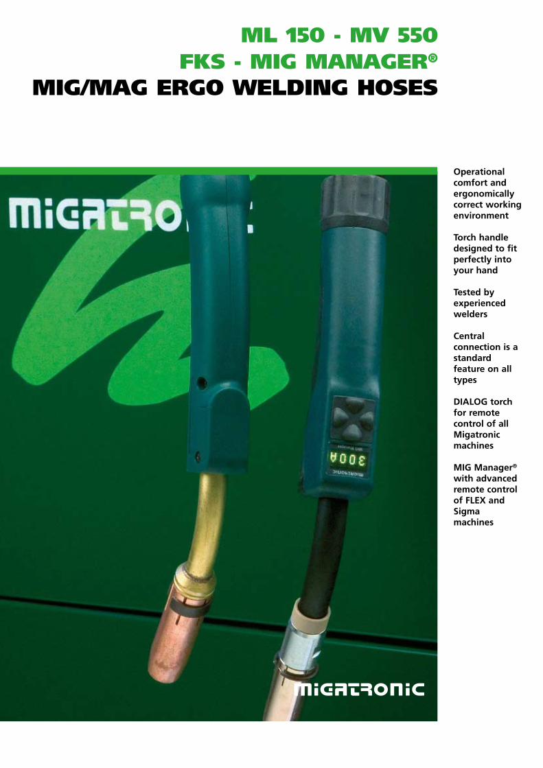
Operational comfort and ergonomically correct working environment
Torch handle designed to fit perfectly into your hand
Tested by experienced welders
Central connection is a standard feature on all types
DIALOG torch for remote control of all Migatronic machines
MIG Manager® with advanced remote control of FLEX and Sigmamachines
ML 150 - Mv 550fks - Mig Manager®
Mig/Mag ergo weLding hoses
New digital operational comfort and ergonomics in the torch handle
With Migatronic's new brochure on MIG/MAG welding hoses at hand you will easily find the welding hose that suits your welding requirements. The following pages will give you an overall impression of the standard types in Migatronic's wide range of ergonomic welding hoses. In addition to the standard types, we develop and design custombuilt special solutions.
Digital revolution
MIG Manager® is the name of Migatronic's digital MIG welding hose which communicates directly with the most advanced FLEX and Sigma welding machines. The MIG Manager® torch handle allows the welder adjustment of all vital parameters and direct output in the green display. The MIG Manager® covers a special requirement when it comes to welding operations where the welder does not have eye contact with the welding machine.
Advanced cooling system
FKS is the essence of Migatronic's watercooled welding hoses with the revolutionary double coolingchamber
ensuring efficient cooling of the torch at the gas nozzle. Large quantities of radiant heat are absorbed from the weld pool and transported to the cooling unit. Migatronic FKS welding hoses are also available with Dialog adjustment of the welding current or with the digital MIG Manager® concept. The FKS has been developed specifically for heavy duty pulse welding and spray transfer welding.
Technology at both ends
Migatronic always endeavours to focus on simplicity and user friendliness; elements that result in satisfaction and, indirectly, better economy. Ballandsocket joint
relief at both ends of the hose is an example of innovative ergonomics as well as use of many combined materials in contact tips, gas diffusers, wire liners etc., all of which contributes to reliability and longer life of the hoses. Migatronic's complete range of watercooled or aircooled welding hoses offers a variety of thoroughly tested highquality products.
MIGATRONIC ABBREVIATIONS
MLMigatronic aircooled torch
MVMigatronic watercooled torch
300 Model size
FRemote control/ Dialog
KDSeparate tip adaptor
TSpring pins in central connection
HD-SHeavy Duty with 10 x 40 mm nozzle
FKSDouble cooling chamber with extra cooling of gas nozzle
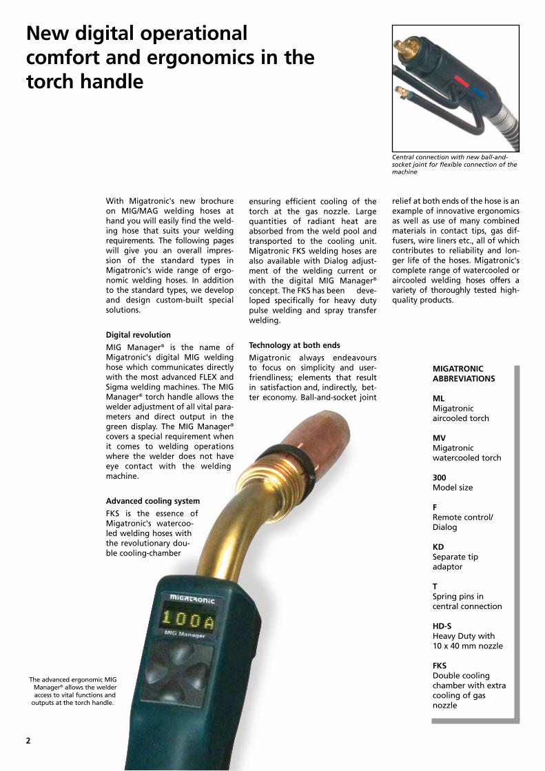
The advanced ergonomic MIG Manager® allows the welder access to vital functions and
outputs at the torch handle.
Central connection with new ball-and-socket joint for flexible connection of the machine
2
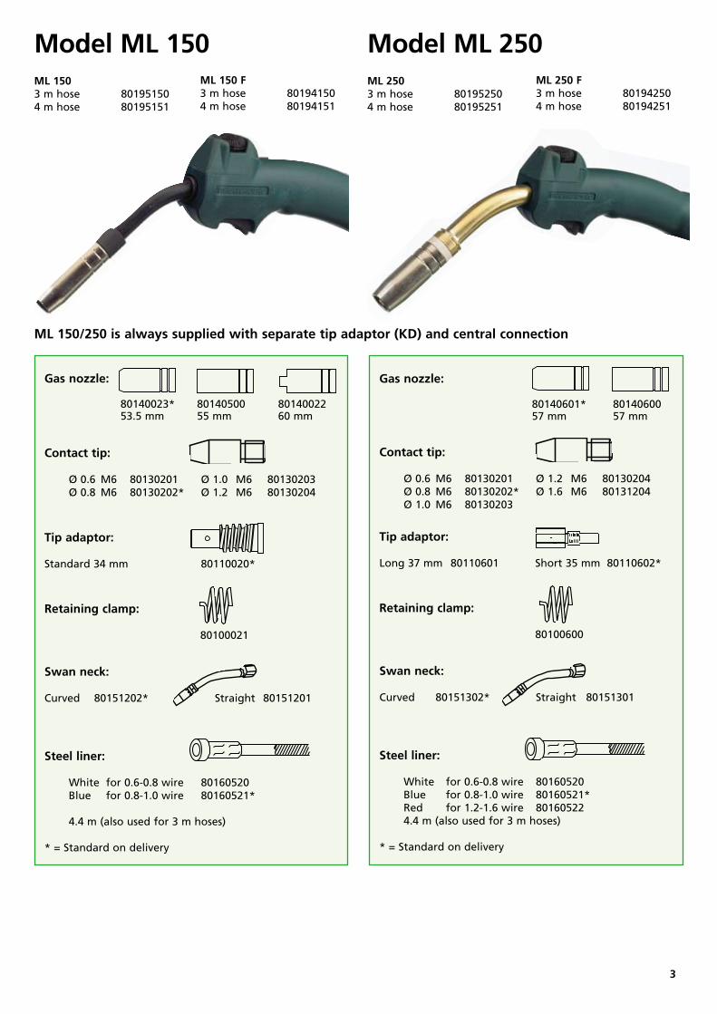
Model ML 150ML 1503 m hose 801951504 m hose 80195151
ML 150 F3 m hose 801941504 m hose 80194151
Model ML 250ML 2503 m hose 801952504 m hose 80195251
ML 250 F3 m hose 801942504 m hose 80194251
Gas nozzle: 80140023* 80140500 80140022 53.5 mm 55 mm 60 mm
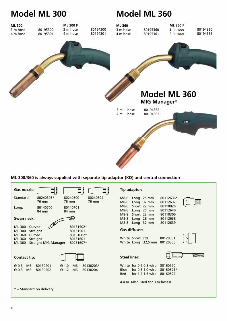
ML 300 Curved 80151502* ML 300 Straight 80151501ML 360 Curced 80151602*ML 360 Straight 80151601ML 360 Straight MIG Manager 80251607*
Steel liner: White for 0.60.8 wire 80160520Blue for 0.81.0 wire 80160521*Red for 1.21.6 wire 80160522
4.4 m (also used for 3 m hoses)
Tip adaptor: M86 Long 25 mm 80112636*M86 Long 32 mm 80112637 M86 Short 22 mm 80110026M86 Long 25 mm 80112640 M88 Short 23 mm 80110300M88 Long 28 mm 80112638M88 Long 32 mm 80112639
Gas diffuser:
White Short std. 80120301White Long 32,5 mm 80120306
4
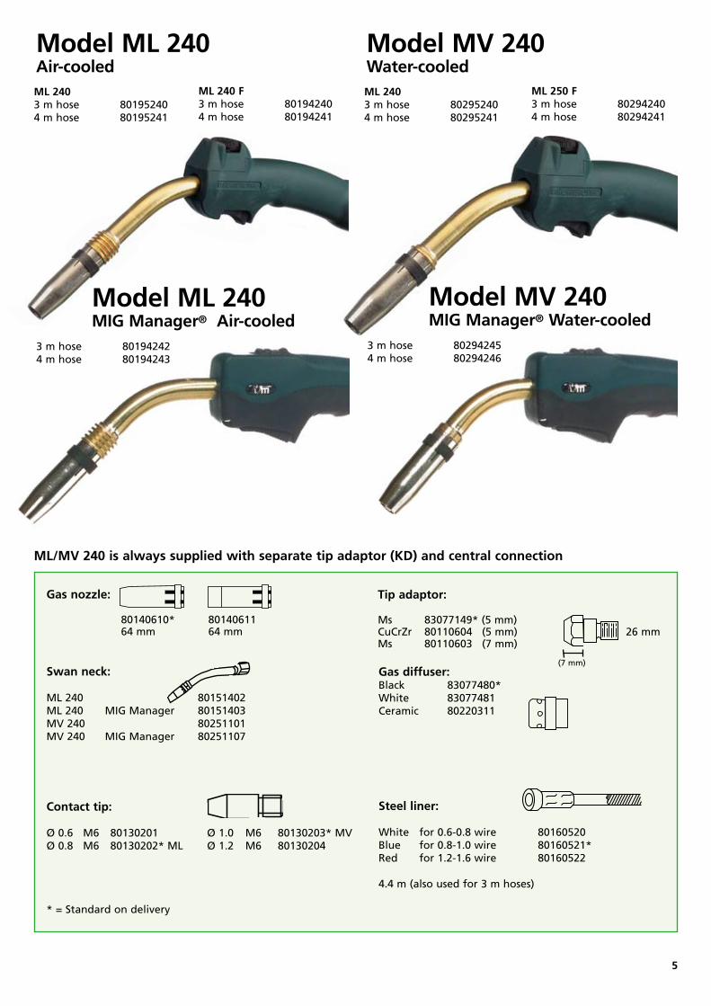
ML 300/360 is always supplied with separate tip adaptor (KD) and central connection
Model ML 240Air-cooledML 2403 m hose 801952404 m hose 80195241
ML 240 F3 m hose 801942404 m hose 80194241
Model MV 240Water-cooledML 2403 m hose 802952404 m hose 80295241
ML 250 F3 m hose 80294240 4 m hose 80294241
Model ML 240 MIG Manager® Air-cooled
3 m hose 80194242 4 m hose 80194243
Model MV 240 MIG Manager® Water-cooled
3 m hose 802942454 m hose 80294246
Gas nozzle: 80140610* 80140611 64 mm 64 mm
Tip adaptor: Ms 83077149* (5 mm) CuCrZr 80110604 (5 mm) 26 mmMs 80110603 (7 mm)
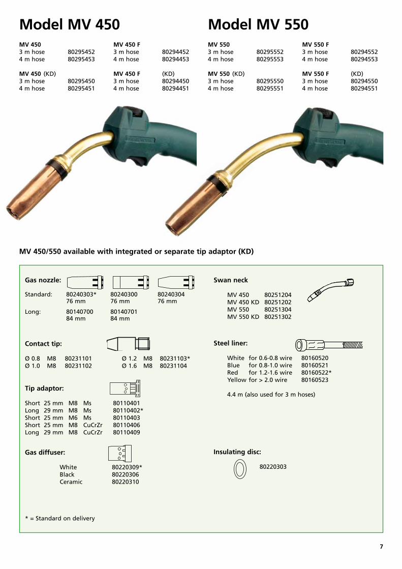
Steel liner: White for 0.60.8 wire 80160520 Blue for 0.81.0 wire 80160521 Red for 1.21.6 wire 80160522* Yellow for > 2.0 wire 80160523
4.4 m (also used for 3 m hoses)Tip adaptor: Short 25 mm M8 Ms 80110401 Long 29 mm M8 Ms 80110402*Short 25 mm M6 Ms 80110403Short 25 mm M8 CuCrZr 80110406Long 29 mm M8 CuCrZr 80110409
Gas diffuser: White 80220309* Black 80220306 Ceramic 80220310
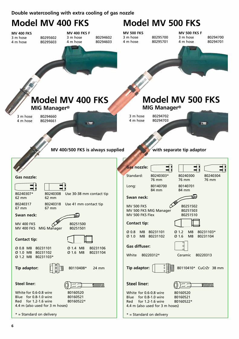
MV 450/550 available with integrated or separate tip adaptor (KD)
Gas nozzle: Standard: 80240303* 80240300 80240304 76 mm 76 mm 76 mm
Long: 80140700 80140701 84 mm 84 mm
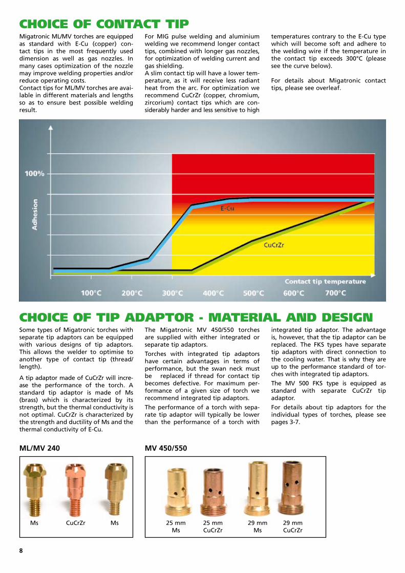
ChoiCe of ContaCt tip
ChoiCe of tip adaptor - MateriaL and design
Migatronic ML/MV torches are equipped as standard with ECu (copper) contact tips in the most frequently used dimension as well as gas nozzles. In many cases optimization of the nozzle may improve welding properties and/or reduce operating costs.Contact tips for ML/MV torches are available in different materials and lengths so as to ensure best possible welding result.
For MIG pulse welding and aluminium welding we recommend longer contact tips, combined with longer gas nozzles, for optimization of welding current and gas shielding.A slim contact tip will have a lower temperature, as it will receive less radiant heat from the arc. For optimization we recommend CuCrZr (copper, chromium, zircorium) contact tips which are considerably harder and less sensitive to high
temperatures contrary to the ECu type which will become soft and adhere to the welding wire if the temperature in the contact tip exceeds 300°C (please see the curve below).
For details about Migatronic contact tips, please see overleaf.
8
Some types of Migatronic torches with separate tip adaptors can be equipped with various designs of tip adaptors. This allows the welder to optimise to another type of contact tip (thread/length).
A tip adaptor made of CuCrZr will increase the performance of the torch. A standard tip adaptor is made of Ms (brass) which is characterized by its strength, but the thermal conductivity is not optimal. CuCrZr is characterized by the strength and ductility of Ms and the thermal conductivity of ECu.
The Migatronic MV 450/550 torches are supplied with either integrated or separate tip adaptors.
Torches with integrated tip adaptors have certain advantages in terms of performance, but the swan neck must be replaced if thread for contact tip becomes defective. For maximum performance of a given size of torch we recommend integrated tip adaptors.
The performance of a torch with separate tip adaptor will typically be lower than the performance of a torch with
integrated tip adaptor. The advantage is, however, that the tip adaptor can be replaced. The FKS types have separate tip adaptors with direct connection to the cooling water. That is why they are up to the performance standard of torches with integrated tip adaptors.
The MV 500 FKS type is equipped as standard with separate CuCrZr tip adaptor.
For details about tip adaptors for the individual types of torches, please see pages 37.
ML/MV 240 MV 450/550
25 mm 25 mm 29 mm 29 mm Ms CuCrZr Ms CuCrZr
Ms CuCrZr Ms
Item no. Item description
M 5
80130140 ø 0.6 M5 ø 5 x 18 mm Cu 80130141 ø 0.8 M5 ø 5 x 18 mm Cu 80130142 ø 1.0 M5 ø 5 x 18 mm Cu M 6
80130001 ø 0.6 M6 ø 6 x 25 mm Cu nickelplated 80130002 ø 0.8 M6 ø 6 x 25 mm Cu nickelplated 80130003 ø 1.0 M6 ø 6 x 25 mm Cu nickelplated 80130004 ø 1.2 M6 ø 6 x 25 mm Cu nickelplated
80130101 ø 0.6 M6 ø 6 x 25 mm Cu 80130102 ø 0.8 M6 ø 6 x 25 mm Cu 80130103 ø 1.0 M6 ø 6 x 25 mm Cu 80130104 ø 1.2 M6 ø 6 x 25 mm Cu
80130201 ø 0.6 M6 ø 8 x 28 mm Cu 80130202 ø 0.8 M6 ø 8 x 28 mm Cu 80130203 ø 1.0 M6 ø 8 x 28 mm Cu 80130204 ø 1.2 M6 ø 8 x 28 mm Cu 80131200 ø 0.8 M6 ø 8 x 28 mm CuCrZr 80131201 ø 1.0 M6 ø 8 x 28 mm CuCrZr 80131202 ø 1.2 M6 ø 8 x 28 mm CuCrZr 80131203 ø 1.4 M6 ø 8 x 28 mm CuCrZr 80131204 ø 1.6 M6 ø 8 x 28 mm CuCrZr
M 8
80231101 ø 0.8 M8 ø 10 x 30 mm ECu 80231102 ø 1.0 M8 ø 10 x 30 mm ECu 80231103 ø 1.2 M8 ø 10 x 30 mm ECu 80231106 ø 1.4 M8 ø 10 x 30 mm ECu 80231104 ø 1.6 M8 ø 10 x 30 mm ECu 80231111 ø 1.0 M8 ø 8 x 35 mm CuCrZr 80231112 ø 1.2 M8 ø 8 x 35 mm CuCrZr 80231113 ø 1.6 M8 ø 8 x 35 mm CuCrZr
80231121 ø 1.0 M8 ø 10 x 35 mm ECu 80231122 ø 1.2 M8 ø 10 x 35 mm ECu 80231123 ø 1.6 M8 ø 10 x 35 mm ECu 80231200 ø 0.8 M8 ø 8 x 30 mm CuCrZr 80231201 ø 1.0 M8 ø 8 x 30 mm CuCrZr 80231202 ø 1.2 M8 ø 8 x 30 mm CuCrZr 80231203 ø 1.6 M8 ø 8 x 30 mm CuCrZr 80231204 ø 1.4 M8 ø 8 x 30 mm CuCrZr 80231205 ø 0.8 M8 ø 10 x 30 mm CuCrZr 80231206 ø 1.0 M8 ø 10 x 30 mm CuCrZr 80231207 ø 1.2 M8 ø 10 x 30 mm CuCrZr 80231208 ø 1.4 M8 ø 10 x 30 mm CuCrZr 80231209 ø 1.6 M8 ø 10 x 30 mm CuCrZr 80231300 ø 0.8 M8 ø 10 x 38 mm CuCrZr 80231301 ø 1.0 M8 ø 10 x 38 mm CuCrZr 80231302 ø 1.2 M8 ø 10 x 38 mm CuCrZr 80231303 ø 1.6 M8 ø 10 x 38 mm CuCrZr 80231304 ø 2.4 M8 ø 10 x 38 mm CuCrZr 80231400 ø 0.8 M8 ø 10 x 41 mm CuCrZr 80231401 ø 1.0 M8 ø 10 x 41 mm CuCrZr 80231402 ø 1.2 M8 ø 10 x 41 mm CuCrZr 80231404 ø 1.6 M8 ø 10 x 41 mm CuCrZr
M 10
80231451 ø 0.8 M10 ø 10 x 40 mm CuCrZr 80231452 ø 1.0 M10 ø 10 x 40 mm CuCrZr 80231453 ø 1.2 M10 ø 10 x 40 mm CuCrZr 80231454 ø 1.6 M10 ø 10 x 40 mm CuCrZr
• = Mild steel Fe, stainless steel CrNi and FCW(•) = Alternative, but we recommend •
• = Aluminium welding • = For gas nozzles with special length: please see torch type
Contact tip - design and length
9
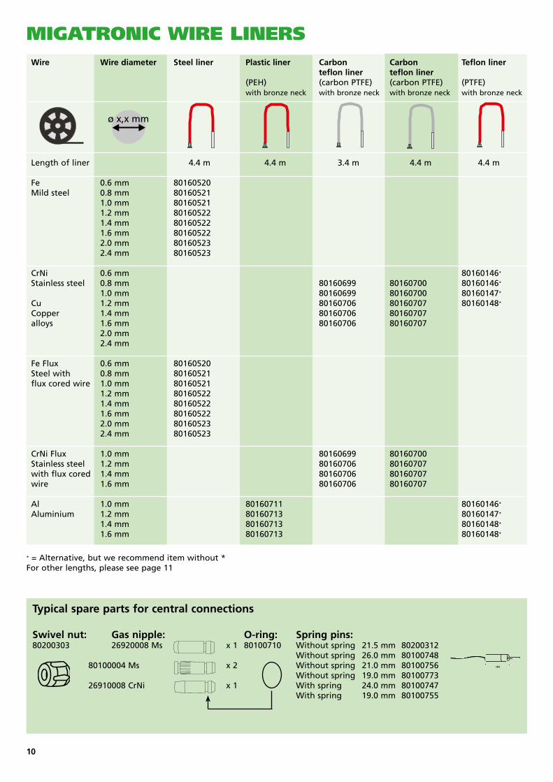
Wire Wire diameter Steel liner Plastic liner Carbon Carbon Teflon liner teflon liner teflon liner (PEH) (carbon PTFE) (carbon PTFE) (PTFE) with bronze neck with bronze neck with bronze neck with bronze neck
Length of liner 4.4 m 4.4 m 3.4 m 4.4 m 4.4 m Fe 0.6 mm 80160520 Mild steel 0.8 mm 80160521 1.0 mm 80160521 1.2 mm 80160522 1.4 mm 80160522 1.6 mm 80160522 2.0 mm 80160523 2.4 mm 80160523
CrNi 0.6 mm 80160146* Stainless steel 0.8 mm 80160699 80160700 80160146* 1.0 mm 80160699 80160700 80160147* Cu 1.2 mm 80160706 80160707 80160148* Copper 1.4 mm 80160706 80160707 alloys 1.6 mm 80160706 80160707 2.0 mm 2.4 mm
Fe Flux 0.6 mm 80160520 Steel with 0.8 mm 80160521 flux cored wire 1.0 mm 80160521 1.2 mm 80160522 1.4 mm 80160522 1.6 mm 80160522 2.0 mm 80160523 2.4 mm 80160523
CrNi Flux 1.0 mm 80160699 80160700 Stainless steel 1.2 mm 80160706 80160707 with flux cored 1.4 mm 80160706 80160707 wire 1.6 mm 80160706 80160707 Al 1.0 mm 80160711 80160146*
Aluminium 1.2 mm 80160713 80160147*
1.4 mm 80160713 80160148*
1.6 mm 80160713 80160148*
MigatroniC wire Liners
Typical spare parts for central connections
Swivel nut: Gas nipple: O-ring: Spring pins:80200303 26920008 Ms x 1 80100710 Without spring 21.5 mm 80200312 Without spring 26.0 mm 80100748 80100004 Ms x 2 Without spring 21.0 mm 80100756 Without spring 19.0 mm 80100773 26910008 CrNi x 1 With spring 24.0 mm 80100747 With spring 19.0 mm 80100755
10
* = Alternative, but we recommend item without * For other lengths, please see page 11
MigatroniC wire Liners
MPL
/V 3
00/4
00 M
K I
MPL
/V 3
00/4
00 M
K I
I
MV
550
FK
S
MV
550
MV
400
FK
S
MV
240
MV
450
ML
360
ML
300
ML2
50
ML
240
ML
150
ML
130
ML
140
Au
tom
ig X
E x
120
D
Au
tom
ig X
R
x 12
0 D
• = Mild steel Fe • = Stainless steel CrNi • = Aluminium welding Al
Au
tom
ig X
x
120
D
•
•
•
• • •
• • • • • • • • • • •
• • • • • • • • • • •
• • • • • • • • • • •
• • • • • • • • • • •
• • • • • • • • • • •
• • • • • • • • • • •
• •
• •
Nippel - design and length
Item no. Item description
80160001 PEH 4.2 m 1.5 x 3.2 51 mm nipple
80160005 PEH 4.2 m 2.0 x 3.2 61 mm nipple
80160020 PEH 4.2 m 1.5 x 3.2 61 mm nipple
80160528 Steel 4.2 m. 1.6 x 3.3 51 mm nipple
80160538 Steel 4.2 m XR 0.81.0 61 mm w/Oring nipple
80160539 Steel 4.2 m XR 0.81.0 51 mm w/Oring nipple
80160533 Steel 4.2 m 0.81.0 /Ø 4.0 light blue without nipple
80160536 Steel 2.0 m 0.81.0 /Ø 4.0 light blue
80160715 PEH white 4.4 m 0.60.8 mm w. 165mm steel neck 80160716 PEH blue 4.4 m 0.81.0 mm w. 165 mm steel neck
80160520 Steel 4.4 m w/nipple 0.6 0.8 white
80160550 Steel 5.4 m w/nipple 0.6 0.8 white
80160521 Steel 4.4 m w/nipple 0.8 1.0 blue
80160551 Steel 5.4 m w/nipple 0.8 1.0 blue
80160518 Steel 8.4 m w/nipple 0.8 1.0 blue
80160522 Steel 4.4 m w/nipple 1.2 1.6 red
80160552 Steel 5.4 m w/nipple 1.2 1.6 red
80160517 Steel 8.4 m w/nipple 1.0 1.6 red
80160523 Steel 4.4 m w/nipple 1.6 2.4 yellow
80160553 Steel 5.4 m w/nipple 1.6 2.4 yellow
80160146 PTFE 4.4 m 0.60.8 Ø 4.0 white Oring screw nipple
80160149 PTFE 5.4 m 0.60.8 Ø 4.0 white Oring screw nipple
80160147 PTFE 4.4 m 0.81.0 Ø 4.0 blue Oring screw nipple
80160150 PTFE 5.4 m 0.81.0 Ø 4.0 blue Oring screw nipple
80160148 PTFE 4.4 m 1.21.6 Ø 4.0 red Oring screw nipple
80160151 PTFE 5.4 m 1.21.6 Ø 5.4 red Oring screw nipple
80160620 PTFE 4.4 m 0.60.8 white Oring screw nipple
80160630 PTFE 5.4 m 0.81.0 white Oring screw nipple
80160621 PTFE 4.4 m 0.81.0 blue Oring screw nipple
80160631 PTFE 5.4 m 0.81.0 blue Oring screw nipple
80160622 PTFE 4.4 m 1.21.6 red Oring screw nipple
80160632 PTFE 5.4 m 1.21.6 red Oring screw nipple
80160623 PTFE 4.4 m 1.62.0 yellow Oring screw nipple