36
ml vW/tgmh Sri LanM rbr&ry rr/stionaiY 217030 888 80 31 70 35 889 64
| Date post: | 13-Apr-2018 |
| Category: |
Documents |
| Upload: | hoangtuong |
| View: | 214 times |
| Download: | 1 times |

ml vW/tgmh Sri LanM
rbr&ryrr/stionaiY
217030 888 8031 70 35 889 64

Construction ofLATRINES
in rural villages in Sri Lanka
LIBRARY IRCPO Box 93190, 2509 AD THE HAGUE
Tel.: +31 70 30 689 80Fax: +31 70 35 899 64
RARCODE: \q_
Swiss Association forDevelopment and Cooperation

First Edition 1994
Published byHELVETAS, Swiss Association for Development and Cooperation
Programme Office - Sri Lanka
Head OfficeHELVETAS
St. Moritzstrasse 15Postfach
CH-8042 Zurich (Switzerland)
Cover PhotoLatrine in Hippola Village, Kandy District(by Sarvodaya Rural Technical Services)
Printed bySarvodaya Vishva Lekha
RatmalanaSri Lanka

FOREWORD
It is with great pleasure that I am writing this message on the occasion of thepublication of this manual which is the result of a joint effort of HELVETAS andSarvodaya Rural Technical Services (SRTS).
The improvement of health conditions of the rural community in Sri Lanka byproviding pure drinking water and improving sanitation facilities is a vital taskperformed by the SRTS. A number of gravity water supply schemes, hand dugshallow wells and latrine projects have been constructed by SRTS in variousdistricts through out the country during the past 15 years to achieve this objective.
In this exercise the SRTS personnel have worked not only as technical people butalso as community development workers, using appropriate technology and suitablemethodologies wherever it is necessary. It is commendable that the SRTS is now ina position not only to contribute to such an important manual through the vastexperience they have gained during the last few years but also to provide thetechnical expertise to other NGOs who are involved in the rural water and sanitationsector in Sri Lanka.
In this connection our sincere thanks should go to our research partners fromHELVETAS, Switzerland, who came with technological expertise, but gave therecognition to our own spiritual cultural resources that we were using in ourmovement. It should be stated that the contribution from HELVETAS financially aswell as technically towards the SRTS activities should be highly appreciated.
Finally, I would like to give my thanks to everybody who made their valuablecontribution towards the publication of this manual.
Dr.A. T. Ariyaratne,Hon. President,Lanka Jathika Sarvodaya Shramadana Sangamaya (Inc.)

TABLE OF CONTENTS
PREFACE 2
1 INTRODUCTION 3
2 HEALTH ASPECTS 42.1 Excreta-Related Infectious Diseases 4
2.2 Prevention of Excreta-Related Diseases 4
3 LOCATION OF LATRINE PITS 5
4 RECOMMENDED TYPES OF LATRINES 64.1 Ventilated Improved Pit Latrine (VIP) 7
4.1.1 Simple Pit Latrine 74.1.2 VIP Latrine 74.1.3 Upgrading of a VIP Latrine 8
4.2 Water Seal (Pour Flush) Latrine 94.2.1 General Information 94.2.2 Upgrading of a Water Seal Latrine 10
5 OPERATION AND MAINTENANCE 115.1 VIP Latrine 115.2 Water Seal Latrine 11
6 TECHNICAL AND CONSTRUCTION DETAILS 126.1 Pits 12
6.1.1 Size of Pits 126.1.2 Pits in Different Soil Conditions 13
6.1.2.1 Pits in Normal (Stable) Soil 136.1.2.2 Pits in Hard Soil 136.1.2.3 Pits in Soft and Sandy Soil 146.1.2.4 Pits in Soil with High Water Table 15
6.2 Construction of Slabs 16
6.3 Placing of Slabs 18
6.4 Construction of Foundations and Placing of SquattingPans for Water Seal Latrines 19
6.5 Superstructure of Latrines 206.5.1 General Remarks 206.5.2 Size of Superstructure 206.5.3 Roofing of Latrines 206.5.4 Samples of Superstructure 21
APPENDIX:References and Bibliography 22Detailed Drawings 22

PREFACE
In 1978, a fruitful partnership commenced between the Sarvodaya Rural TechnicalServices (SRTS) and HELVETAS. In the beginning a small but motivated unitsupported the Sarvodaya Shramadana Movement by providing training to youngmen and women in agriculture and artisan skills.
Initially SRTS was engaged mostly in the northern districts of Sri Lanka but withincreasing numbers of skilled staff its activities were successfully extended to theother parts of the island. Over the years there was a shift from training andagricultural activities towards more technical (rural infrastructure) projects. SRTSspecialised in assisting the rural communities in improving the infrastructure of theirvillages through the construction of Gravity Water Supply Schemes, Hand-DugWells, Bridges, Culverts, Latrines etc.
The large number of similar projects implemented by SRTS made it advisable tostandardize the design and construction procedures. The manuals and standarddrawings which were consequently prepared by the senior SRTS staff together withthe HELVETAS engineers reflect the experiences gained throughout the years.
In August 1991, HELVETAS decided to update and to revise all these technicalpapers with the broader aim to make them available not only to SRTS but also toother organisations, institutions or individuals interested and engaged in this field ofwork. As a result of these efforts the following manuals are now available:
- "Construction of Latrines in Rural Villages in Sri Lanka"(also available in Sinhala and Tamil)
- "Construction of Hand-Dug Wells in Rural Villages in Sri Lanka"(also available in Tamil and Sinhala)
- "Design, Construction and Standardisation of Gravity WaterSupply Systems in Rural Villages in Sri Lanka"(available also in Sinhala)
It should be noted that these manuals are technical handbooks for those involved inthe planning and construction of hand dug wells, gravity water supply systems andlatrines. Other related aspects of such projects, like health education, participatoryplanning and involvement of the villagers in the construction phase or maintenanceof completed projects are only touched or not discussed at all.
We are grateful to all who contributed to the completion of these manuals and wouldappreciate comments or suggestions for further improvements. For any inquiries youcan contact our office under the following address:
HELVETAS, 15/2, Ekanayake Avenue, Nugegoda (Sri Lanka)Tel. 01 -85 24 54; Fax: 01 -81 19 92
Nugegoda, March 1994
-2-

0 INTRODUCTION
Inadequate disposal of human excrement is a major health hazard which can beprevented through the use of good latrines. According to recent studies, only about40% of the rural households in Sri Lanka are equipped with latrines in good or faircondition of the water seal or pit type. This manual should enable interested persons,institutions or organisations to design and construct appropriate latrines for the ruralareas of Sri Lanka.
This manual briefly touches the health aspects of latrines but mainly concentrates onthe following:
- Location of Latrine Pits
- Recommended Types of Latrines
- Operation and Maintenance of Latrines
- Construction Details
- Detailed Drawings
- References
It is important to realise that the construction of latrines alone will not improve healthconditions. There has to be an accompanying hygiene education program to makethe people aware of the importance of personal hygiene.
The Appendix to this manual includes references and a bibliography for furtherreading.
-3-

Q HEALTH ASPECTS
2.1 EXCRETA-RELATED INFECTIOUS DISEASES
An infectious disease is one which can be transmitted from one person to anotherdirectly or indirectly. All infectious diseases are caused by living organisms, such asbacteria, viruses, or parasitic worms, and a disease is transmitted by the passing ofthese organisms from one person's body to another. Excreta-related diseases arecaused by pathogens transmitted in human excreta, normally in the faeces.
FINGERS
Transmission of Excreta-related Diseases
2.2 PREVENTION OF EXCRETA-RELATED DISEASES
Improved excreta disposal (through latrines) is an important factor in preventingexcreta-related diseases. Other factors are:
- Improved Water Supply- Personal Cleanliness- Efforts in Health Education, etc.
However, there is evidence that the use of a fouled/dirty latrine in rural areasprovides a greater health hazard than the practice of casual defecation in thesurrounding bush.
It is essential that people of all age groups use the improved latrines andkeep them clean. Children's excreta is equally as infectious as adults'.
-4-
LOCATION OF LATRINE PITS
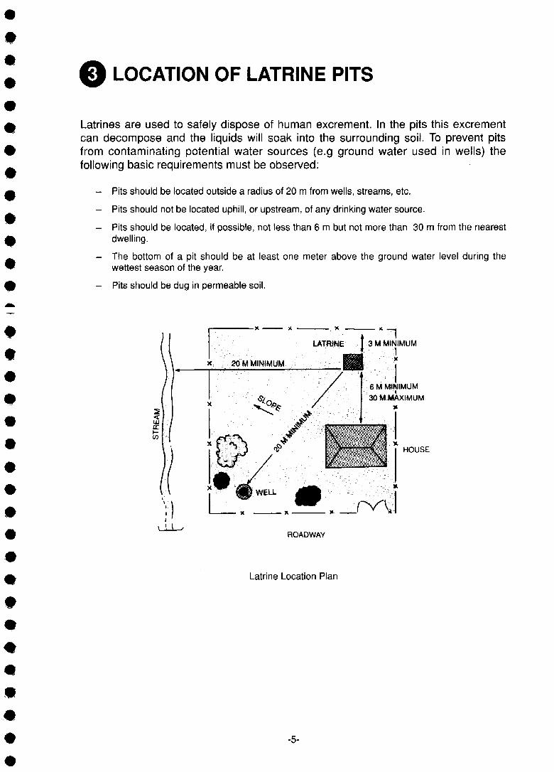
Latrines are used to safely dispose of human excrement. In the pits this excrementcan decompose and the liquids will soak into the surrounding soil. To prevent pitsfrom contaminating potential water sources (e.g ground water used in wells) thefollowing basic requirements must be observed:
- Pits should be located outside a radius of 20 m from wells, streams, etc.
- Pits should not be located uphill, or upstream, of any drinking water source.
- Pits should be located, if possible, not less than 6 m but not more than 30 m from the nearestdwelling.
- The bottom of a pit should be at least one meter above the ground water level during thewettest season of the year.
- Pits should be dug in permeable soil.
1LATRINE I 3 M MINIMUM
6 M MINIMUM
30 M MAXIMUM
HOUSE
ROADWAY
Latrine Location Plan
-5-

RECOMMENDED TYPES OF LATRINES
The two basic types of recommended latrines are:
Ventilated Improved Pit Latrine (VIP) Water Seal (Pour Flush) Latrine
Air movement
Corrigendum:Please exchange
pictures!
The VIP latrine is a good solution ifthere is little or no water available!
For more details please refer to:
- 4.1 General Information
- 5.1 Operation and Maintenance
- 6.1 Pits
- 6.3 Placing of Slabs
- 6.4 Foundation, Squatting Pan
- 6.5 Superstructure
- Appendix: Detailed Drawings
Air movement
is pit lining
The water seal latrine is a goodsolution if there is enough wateravailable, min. 3 litres per flush!
For more details please refer to:
- 4.2 General Information
- 5.2 Operation and Maintenance
- 6.1 Pits
- 6.3 Placing of Slabs
- 6.4 Foundation, Squatting Pan
- 6.5 Superstructure
- Appendix: Detailed Drawings
-6-

4.1 VENTILATED IMPROVED PIT LATRINE (VIP)
4.1.1 SIMPLE PIT LATRINE
The conventional, simple pit latrine (see picture) hastwo principal disadvantages:
- It smells.
- It produces hundreds of flies (ormosquitoes) a day.
Therefore the simple pit latrine is not recommended!
Air movement
4.1.2 VIP LATRINE
For standard drawing No. L -1 please refer to the Appendix!
The disadvantages of the simple pit latrine are reduced in the ventilated improved pitlatrine (VIP). See picture below:
The ventilation pipe is the key tocontrolling odours and flies by allowing aconstant flow of air down through thesquatting hole and up the vent pipe. Thisflow of air is induced partly by convectioncaused by the warmth of the sun on theexternal vent pipe, and partly by the windblowing over the top of the vent pipe. Fliesattracted by the odours of the pit will entervia the drop hole and lay their eggs. Whennew adult flies emerge they instinctivelyfly towards the light; however, if the latrineis suitably dark inside the only light theycan see is at the top of the vent pipe. Ifthe vent pipe is provided with a suitable flyscreen at its top, the newly hatched flieswill not be able to escape and they willeventually fall down and die in the pit.
Air movement
pit lining
-7-

Once the pit is full with excreta (up to 50 cm of ground level), a new pit has to be dugand the latrine has to be moved to the new pit. The old pit has to be filled with earthand sealed. After about one year the contents of the pit can be used as compost,where such practise is culturally accepted.
Some important points for the proper functioning of a VIP latrine:
- The entrance of the latrine should face the main wind direction.
- The vent pipe should be located on the sunny side of the latrine, should be painted with darkcolour (absorbs more sun light and increases thereby the air flow) and should be high enoughand down-wind of the dwelling.
- Size of the vent pipe: 75 mm < diameter < 200 mm.
- There should be sufficient ventilation openings to provide the latrine with fresh air.
- The latrine should be kept sufficiently dark but not too dark to use. A wooden cover for the drophole may be provided (ensure air circulation through the covered drop hole).
- Do not compromise on the diameter and the height of the vent pipe (min. 50 cm higher than theroof).
4.1.3 UPGRADING OF A VIP LATRINE
Through the construction of a twin pit a VIP latrine can become a permanentstructure, since it does not need to be moved once the first pit is full. The users of thelatrine simply switch to the squatting hole of the second pit (within the same latrinesuperstructure). After about one year the contents of the first pit can be removed andused as compost / manure (where acceptable).
Fly screen
Alternate pit squat holetemporarily sealed
Vent pipe
Alternate pit vent pipe hole
Removable cover slabs
Sludge saferemoval afte
-8-
4.2 WATER SEAL (POUR FLUSH) LATRINE
4.2.1 GENERAL INFORMATION
For standard drawing No. L - 2 please refer to the Appendix!
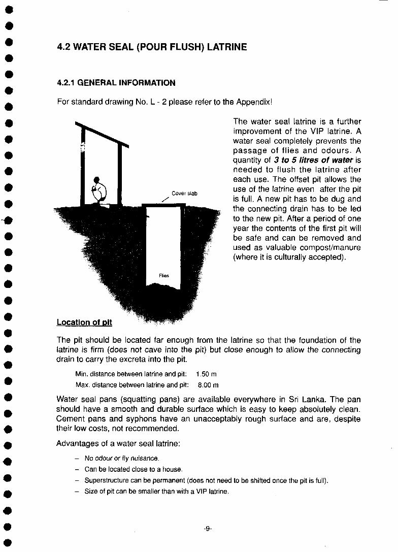
The water seal latrine is a furtherimprovement of the VIP latrine. Awater seal completely prevents thepassage of flies and odours. Aquantity of 3 to 5 litres of water isneeded to flush the latrine aftereach use. The offset pit allows theuse of the latrine even after the pitis full. A new pit has to be dug andthe connecting drain has to be ledto the new pit. After a period of oneyear the contents of the first pit willbe safe and can be removed andused as valuable compost/manure(where it is culturally accepted).
Location of pit
The pit should be located far enough from the latrine so that the foundation of thelatrine is firm (does not cave into the pit) but close enough to allow the connectingdrain to carry the excreta into the pit.
Min. distance between latrine and pit: 1.50 m
Max. distance between latrine and pit: 8.00 m
Water seal pans (squatting pans) are available everywhere in Sri Lanka. The panshould have a smooth and durable surface which is easy to keep absolutely clean.Cement pans and syphons have an unacceptably rough surface and are, despitetheir low costs, not recommended.
Advantages of a water seal latrine:
- No odour or fly nuisance.
- Can be located close to a house.
- Superstructure can be permanent (does not need to be shifted once the pit is full).
- Size of pit can be smaller than with a VIP latrine.
-9-

Disadvantages of a water seal latrine:
- Sufficient water has to be available within a reasonable distance (min. 3 liters per flush).
- Use of material for cleansing (e.g. towels, plastic, etc.) or careless handling may causeblockage of syphon and requires attention and maintenance.
4.2.2 UPGRADING OF A WATER SEAL LATRINE
Instead of digging a second pit only after the first pit is full, two pits could beconstructed from the beginning according to the sketches below.
Section
Water sealpan
Soak awaypit
Openbrickwork
Plan
Pit 1
Pit 2
Drain junction with blockedoutlet to pit not in use Removable cover
slabs
after oho year
Upgraded Water Seal Latrines (Twin Pit)
Water seal latrines can also been upgraded through the construction of a small watertank/container adjoining the latrine.
-10-

0 OPERATION AND MAINTENANCE
5.1 O & M OF A VIP LATRINE
- Ensure that there is an efficient drainage around the latrine to prevent thelatrine from being flooded.
- Wash hands with soap after using the latrine !
- After each use, sprinkle a small amount of ash or soil through the hole tohelp eliminate odours and prevent fly breeding.
- Every day, wash the latrine floor and the edges of the squatting holethoroughly by using a toilet brush. From time to time (once a week), usedisinfectants.
- Use the cover for the squatting hole and shut the door after using the latrine.
- Keep the vent pipe clear and free of leaves.
- Maintain the fly screen on top of the vent pipe frequently
- Maintain the superstructure of the latrine.
5.2 O & M OF A WATER SEAL LATRINE
- Ensure that there is an efficient drainage around the latrine to prevent it frombeing flooded.
- Wash hands with soap after using the latrine I
- After using the latrine, flush it with a bucket of water and refill the bucketimmediately so that it is ready for the next user.
- Avoid using bulking materials for cleansing to prevent the syphon fromgetting blocked.
- Water must be readily available (keep a full bucket inside the latrine).
- Every day, wash the latrine floor and the edges of the squatting holethoroughly by using a toilet brush. From time to time (once a week), usesoap or ash.
- Maintain the superstructure of the latrine.
-11-

o TECHNICAL AND CONSTRUCTION DETAILS
6.1 PITS
6.1.1 SIZE OF PITS
The size of a pit directly determines the period of time a pit can be used until it isfilled up. The larger the pit, the longer it lasts. The volume of a pit depends on thecross section and the depth of the pit. The cross section is given by the max. size ofthe covering slab. Experience shows that a pit size of 90 by 90 cm is mostreasonable because the covering slab for such a pit is neither too heavy nor tooexpensive. Therefore, we can say that the volume of the pit can be increased bydeepening it - the deeper the pit, the longer it lasts!
The period of time it takes until a pit is filled up can be roughly calculated with thefollowing formulas:
VIP type: V < 0 .06xPxY V = Volume of pit in m3P = Persons using the pit
Water seal type: V < 0.04 x P x Y Y = Years of anticipated life of pit
As the cross section of a pit is fixed to 0.9 by 0.9 m we can develop a formula for thedepth of a pit. Please note that the top 0.5 m can not be used as the pit has to beemptied or filled with earth before it is completely full.
Formulas to calculate the depth of pits:
0.06 x P x YVIP type: D < +0.5
0.9 x 0.9
D = depth of pit in m
0.04 x P x YWater seal type: D < • — +0.5
0.9x0.9
Example. A family of six wants its pit of a VIP latrine to last at least for ten Years.Therefore, the depth D of the pit should be:
0.06x6 x 10D < +0.5 = 4.95 m
0.9x0.9 •-• —
-12-

6.1.2 PITS IN DIFFERENT SOIL CONDITIONS
6.1.2.1 Pits in Normal (Stable) Soil
The know-how to excavate pits is readily available all over Sri Lanka (due to the widespread digging of shallow wells).
6.1.2.2 Pits in Hard Soil
If the soil is too hard or rocky to dig deep enough, the pit may be made larger at thebottom or extended on one side as shown in the sketch below. Note that for waterseal latrines the soil must be permeable, otherwise the pit will fill too quickly.
Enlarged Pits in Hard or Rocky Soil
-13-

6.1.2.3 Pits in Soft or Sandy Soil
If there is a danger that the pit might cave in due to soft soil the whole pit has to belined. The lining can be done in various ways e.g.:
Burned bricks set in mortarConcrete blocks
- Stone masonry- Porous concrete rings, etc,
Example:
In loose soil where the pit cannot be
excavated vertically, the space
between the lining of the pit and the
slope of the excavation has to be
backfilled (with excavated material)
and well compacted. The bottom of
the pit has to be sealed with a clay
layer or a polyethylene sheet (see
sketch).
-14-

6.1.2.4 Pits in Soil with a High Water Table
When the ground water level is high, the construction of pits becomes very difficult.They tend to collapse in the wet season, and there is a danger of Culex pipiensmosquitoes breeding in pits with high water levels. In such cases a built-up pit isappropriate, as shown in the sketch below.
Built - Up Pits
-15-
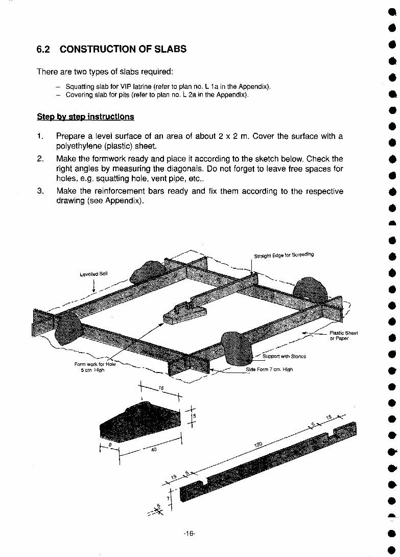
6.2 CONSTRUCTION OF SLABS
There are two types of slabs required:
- Squatting slab for VIP latrine (refer to plan no. l_ 1 a in the Appendix).- Covering slab for pits (refer to plan no. L 2a in the Appendix).
Step bv stGD instructions
1. Prepare a level surface of an area of about 2 x 2 m. Cover the surface with apolyethylene (plastic) sheet.
2. Make the formwork ready and place it according to the sketch below. Check theright angles by measuring the diagonals. Do not forget to leave free spaces forholes, e.g. squatting hole, vent pipe, etc..
3. Make the reinforcement bars ready and fix them according to the respectivedrawing (see Appendix).
Straight Edge for Screeding
Levelled Soil
Support with Stones
Sidu Horm / cm. High
-16-

4. Mix stiff plastic concrete in ratio 1:2:3 (cement:sand:gravel)
Detailed quantities:
cement: 0.035 m3 = 351. = one 50 kg bag
dry sand: 0.070 m3 = 701.
gravel: 0.105 m3 = 1051. (max. grain size: 12 mm)
Note: When using wet sand (which is bulkier than dry sand) the volume should be increasedby about 25 %. The total volume of above materials is 0.21 m3 = 210 I. which isequivalent to about 0.14 m3 of mixed finished concrete. It is quite convenient to use agauge box (see sketch below) for measuring the volume of the materials. Areasonable size would be 0.027 rr>3 = 27 I. Always use clean water, sand and gravel.
Size: VolumeLengthWidthHeight
27= 0.30= 0.30= 0.30
I.mmm
Note: The above measurements are insidedimensions!
5. Pour about 2 cm of concrete over the whole area of the slab and tamp it.
6. Place reinforcement in correct place (according to drawing L 2a in theAppendix).
7 Fill the whole form with concrete and compact it well. Use fine cement mortar(1:3) for the edges (e.g. around squatting hole) and bevel the edge.
8. Screed the top of the slab according to the design (ensure slope towardssquatting hole) and float the top using cement mortar 1:3.
9. Cast the two foot rests (for the VIP latrine) using stiff cement mortar 1:3.
10. Smooth the top of the slab (except the foot rests) with a trowel. Add somecement to the wet topping.
11. As soon as the surface hardens, cover the slab with wet material (e.g.mats,gunny bags, etc.) and keep it wet for at least one week. The formwork can beremoved after one day, but the slab can only be moved after one week.
-17-

6.3 PLACING OF SLABS
The slabs have to be placed on a foundation. The foundation also acts as a lining ofthe top of the pit (refer to pictures below).
Step bv step instructions:
1. Excavate the space for the foundation of the slab (lining of pit).
Thickness min. 30 cm Depth min. 50 cm
2. Build the foundation walls (lining) with hard stones and clay (or cement inexceptional cases). Be careful to fill all gaps between the stones and theground with clay. The walls should be built at least 10 cm higher than theexisting terrain. The last course should be constructed with big stones and beplaced to level.
3. Clean the top of the walls (lining) with water.
4. Place a heap of stiff cement mortar 1:4 all around the top of the wall (lining).
5. Place the slab carefully on top of the walls (lining) into the mortar. Level theknocking it into place as shown in the picture below.
#
Mortar 1 :4 • • • Level
^
6. Smooth the mortar along the face of the slab according to the sketch below.
Mortar 1 :4
-18-
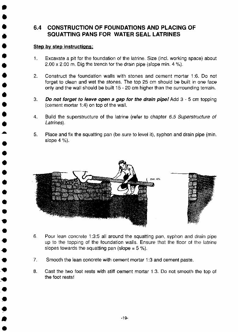
6.4 CONSTRUCTION OF FOUNDATIONS AND PLACING OFSQUATTING PANS FOR WATER SEAL LATRINES
Step by stop instructions:
1. Excavate a pit for the foundation of the latrine. Size (incl. working space) about2.00 x 2.00 m. Dig the trench for the drain pipe (slope min. 4 %).
2. Construct the foundation walls with stones and cement mortar 1:6. Do notforget to clean and wet the stones. The top 25 cm should be built in one faceonly and the wall should be built 15 - 20 cm higher than the surrounding terrain.
3. Do not forget to leave open a gap for the drain pipe! Add 3 - 5 cm topping(cement mortar 1:4) on top of the wall.
4. Build the superstructure of the latrine (refer to chapter 6.5 Superstructure ofLatrines).
5. Place and fix the squatting pan (be sure to level it), syphon and drain pipe (min.slope 4 %).
min. 4%
6. Pour lean concrete 1:3:5 all around the squatting pan, syphon and drain pipeup to the topping of the foundation walls. Ensure that the floor of the latrineslopes towards the squatting pan (slope = 5 %).
7. Smooth the lean concrete with cement mortar 1:3 and cement paste.
8. Cast the two foot rests with stiff cement mortar 1:3. Do not smooth the top ofthe foot rests!
-19-

6.5 SUPERSTRUCTURE OF LATRINES
6.5.1 GENERAL REMARKS
The users of a latrine should enjoy some privacy and protection. The walls of alatrine will give the privacy whereas the roof protects the users.
There are many different alternatives to construct the walls of a latrine. Beforedeciding on a particular variant one should consider the following:
- What is the style of the house to which the latrine belongs?
- How much money is available to construct the latrine?
- What raw materials are easily available (locally)?
- Preferences of the users;
- Maintenance/repair of superstructure.
6.5.2 SIZE OF SUPERSTRUCTURE
A latrine should be big enough to allow comfortable use yet as small as possible.Experiences in many different countries show that the following dimensions are mostappropriate (inside dimensions in cm):
•
*
#
Plan View Section
8
I I80 - 400
200
Detailed drawings of a VIP and a water seal latrine are given in the Appendix(see drawings no. L - 1 , L -1 a, L - 2, L - 2a).
6.5.3 ROOFING OF LATRINES
Several examples of possible solutions to cover a latrine are shown in the sketches(next chapter).
Traditional techniques and skills should be taken into account before deciding on aspecific roof. The users of the latrine should decide what kind of roof they want, sothat they will be able to do some basic repair and maintenance works on the roof.
-20-

6.5.4 SAMPLES OF SUPERSTRUCTURE
A) Mud and wattle walls andpalm thatch roof
C) Brick and tile
plaster
B) Timber walls and corrugatediron or asbestos cement roof
D) Rough cut tree limbs and logs
F) Cadjan
The technologies for types A, B, D and F are readily available in Sri Lanka and thereis no need to give more explanations about them in this manual. More details abouttypes C and E are given in the detailed drawings in the Appendix. The users of thelatrine should decide on the type of the superstructure.
-21-

A P P E N D I XREFERENCES AND BIBLIOGRAPHY
Cairncross, S. and Feachem, R.G. (1990). Environmental Health Engineering in the Tropics: An Introductory Text(London: John Wiley).
Eshuis, J. and Marschot, P. (1978). Communicable Diseases: A Manual for Rural Health Workers (Nairobi:African Medical and Research Foundation).
Feachem, R.G. and Cairncross, S. (1978). Small Excreta Disposal Systems, Ross Institute Bulletin No. 8(London: Ross Institute).
Feachem, R.G., Bradley, D.J., Garelick, H. and Mara, D.D. (1983). Sanitation and Disease: Health Aspects ofExcreta and Wastewater Management (London: John Wiley).
National Water Supply and Drainage Board, Sri Lanka (1988). Design Manual 6, Guidelines for Latrine Selectionand Construction (Colombo: Water Supply and Sanitation Sector Project, USAID Sri Lanka Project).
National Water Supply and Drainage Board, Sri Lanka (1985). Report on Sanitation Programme of Haldumulla, aVillage Community in Sri Lanka (Colmbo: NWSDB, Sri Lanka).
Pacey, A. (1980). Rural Sanitation: Planning and Appraisal (London: Intermediate Technology Publications).
SKAT and ATOL (1985). Manual for Rural Water Supply (St. Gall: SKAT).
Stark, R. and HELVETAS-Team Sri Lanka (1985). Manual for the Construction of Latrines in Sarvodaya Villagesin Sri Lanka (Kandy: Sarvodaya Rural Technical Service).
Stark, R. and HELVETAS-Team Sri Lanka (1987). Construction Manual for Ventilated Improved Pit Latrines (VIP)(Kandy/Buhwil: Sarvodaya Rural Technical Service).
Stark, R. and HELVETAS-Team Sri Lanka (1987). Construction Manual for Water Sealed Latrines (Kandy/Buhwil:Sarvodaya Rural Technical Service).
Waterlines (various publications, WECD).
Technical Brief No. 2 / An Introduction to Pit Latrines
" 6 / Choosing a Water-Seal Latrine
" 23 / A Guide to Sanitation Selection
Whyte, A. (1983). Guidelines for Planning Community Participation in Water Supply and Sanitation Projects(Geneva: WHO).
DETAILED DRAWINGS
Number
L-1
L-1a
L-2
L-2a
Title
VENTILATED IMPROVED PIT LATRINE, VIP
SQUATTING SLAB FOR VIP LATRINE
WATER SEAL (FOUR FLUSH) LATRINE
COVERING SLAB FOR PITS
-22-

SQUATTING SLAB FOR VIP LATRINEVIP
Plan No.
Scale:
Map Sheet:
L-1a
1:20
Date:
Drawn by:611601 f j IT) g j 611 [T
Designed by:rf1i_Li L61I_LI SUIT
March 1992
Kumuduni
R. St. AH.Pf
Amendments
^ 2 5 3 C3
Date:38aBy:
cement
sand
metalurrw
re-rods
timber
/ List of Materials /
0.750.75 bags0.75 Qurr^laerr
8-10 (60 L)8-10 pans (60 L)8-10 3,ns-&s>m (60 L)
roaSS 10-12 (70 L), SGSOC ysi3«6c3 = ©.©. 12.5
10-12 pans (70 L),max. size = 12.5 mm10-12 s,n3Ss,en (70 L J . ^ a a s^ii/.\u ^letroj 12.5 u5l
10 m 0 6mm, w = 2.310 i£. 0 6 ifl.ifi., w = 2.
for form workQuill?.
10 w = 2.3
1 piece

27 n 20 n 26 n 20 n 27
P L A N V I E W 6B)U»Li4LJ u
to be smoothed with cement paste
PVC 3.®. 100
«_ vent pipe, pvc 100 mmj pvc 100 &
0 @.@. 6
re-rods 0 6 mmLSOT a,iJDifla,Ktr 0 6 USI.LB.
A-A SECTION A-A A-A

VEM
I •
1 .-a
Sheet:
Lining o
mud brie
B san<
timber
roofing s
nails
wire
a. s, e.pvc pipepVC
fly screen
\
N,
*\
s.
30 10,\ | \ |> r
36
180
>
64
rr30
r
P L A N V I E W ^)60)IDLJL|U ui_^C?$rT(pn)iiD
List of Materials /
Lining of pit: (incl. placing of slab)0£l
cement
zs>@»cf rubble *«
0£ sand u>«b
0.5 ^^300 0.5 bags 0.5
450 zs»g 450 pcs 450 §j«iror®*6rT (0.9 m3)
8-io ^QB e-10pans 8-10 &*** (65 L)

PVC 0 100 mm/vent pipe, pvc 0 100 mm/ .3,rTr!)(BrT)rTLi_s,
G. I. zarag /G.I. sheet/G.l.^ewg^
/Timber 5 x 7.5
/ventilation hotes/*rrrr)CSrDrTLli_
/wooden door/LDij«.*s&j
/mud brick wa\\/Q&m}8,ri) s,enn
1:2 epaaa^aO (BOcfeisS) (B^Sd^ q>3(scf8!55 SQ
plastering (out side), 2 coats spatter dash 1:21:2
plastering (inside), h = 50 cm to be smoothed with cement paste50
squatting slab, refer to standard drawing L-1a6USB1IJULIXI L " 1 3 jjDLJ
1:4 /motar bed 1:4/si6u6!n6Uff, geirib 1:4
stone masonry built with clay
A-A SECTION A-A iSliflaj A-A
Labour Requirement/<S^6D)6iJujn:«jT
skilled labourrff^l Qu[T)p}
-.3.5 - 4 ^35- 3 . 5 - 4 mandays
~ 3.5 - 4 Loasflg
~4-5
<or pit - 1 2 mandays superstructure ~ 4 ^ mandays

VENTILATED IMPROVED PIT LATRINE (VIP)LJKO0h.l_Lb
kiNo
Je:
: Sheet:UUUUff,
L-1
1:20
Date:
Drawn by:
Designed by:
April 1992
Kumuduni
ff. Sf. & H. Pi
Amendments
Date:§8255
By:
ipUD)
S©M/ List of Materials /
Lining of pit: (incl. placing of slab) /
cement £0iD|bgj 1.5 &Si-£>'o 1.5 bags 1.5
s»«" »-L.UI_)
mud bricks
sand uxsrorsu
timberLDIJlb
roofing sheets
nails
wire
8.3.8. OTCpvc pipePVC ©ijrTUJ
fly screen
30-35
260 260 pCS 260 §\6m®a,en (22.5 X 10.5 X 7.5 C m )
30-35 pans 30-35 g,rr&A3,en (240 L)
aO Q 2 (5 x 7.5 <»(a.®.),^ui = 180 toca.@. ,IB^:I<J wen o<;)ii c3:>e|i; (70 x 180
2 pes purlins (5x 7.5 cm),L = 180 cm ,1 pc door with frame (70 x 180 cm)2 ajssisiT iDrri!Uft6Tr 5 x 7.5 Qff.ifi., L = 180
(70 X 180 Q*.i£.)
) ' ^ 3 (lisea.©. 180 x 60, to^cB 32)
3 pes (180 x 60 cm, 32 gage)3 §]6j(ir@«,6rT (180x60Q*.i£. , 32
j ) 12 - (iijiasS e3aioi,@i?3<5 <33§ w3 zSScsi cs^ai) &co.S. 7.5
12 pes roofing nails with washers 7.5 cm nails for door frame anchorage12 aiirsjit s -aw «^«>7 ^ t r fas i f . agaj jglemfiusniLiLi &ss\miig,in 7.5 Q*.Ji,
Sufi 4 K54 m of 2 mm wire (for anchorage)i51«n«!i!rggrr)«fT6BT ftygeir a.ibi5l, 2 lil.ifi. «,ii>dl 4 d5.
= 26Ocm,0 = 100 mm
pvc mosquito mesh, ~0.1m2

8
8.3.3. znc 0 ®-®pvc pipe 0 90 mmPVC <g,igfTuj 0 90
Qb Roof Line
30
120
101 20 40
180
40 30
S
ao
ooCM
PLAN VIEW
List of Materials /
Lining of pit: (Incl. placing of slab) cement
rubble
sandLD65BTS0
0.50.5 bags0.5
0.9 m3)450 pcs (0.9 m3)450 §j«5Br@«efr (0.9
8-10 pans (65L)

pvc pipe 0 90 mm slope min. 4%pVC ©ijrruj 0 90 lil.ifi. <g,6mp3!!)«,§i 4 %
G.I. Z»5»gG.I. sheet
@e. ®. 5 x 7.5Timber 5 x 7.5 5 x 7.5 Q&.&.
' ventilation holes
• wooden door
Plar
Sea
Map
#
- mud brick wall §
8 0 Ssf tS 1:2 epgesoSBcs© <s«$Sd2s5
, plastering (out side) 2 coats spatter dash 1:2
>es. ®. 5 0 as!. _
plastering (inside), h = 50 cm to be smoothed with cement paste
3 cm Topping coat 1:3, smoothed with cement paster ^Q 3 GW.J). (SiflfTjyj ft 1 ;3
1:3:5concrete 1:3:5, cast in-situ
1:3:5, rfli
1.6Foundation in stone masonry built with cement mortar 1:6
'filled with stones
A-A SECTION A-A iSlrfleij A-A
Labour Requirement
Skilled LabourQujbiD
Unskilled Labour
S©/latrine
/latrine /wsos*,
i 1 manday 13.5-4 3.5-4 mandays/ Loafl I6tn_a6ir
12-14 12-14 mandays 12/14,4 5 ,4-5 mandays 4-

WATER SEAL (POUR FLUSH) LATRINEUL| ($©0)0)60) LD6O*i.l_lJD
iNo.
le:
> Sheet:
L-2
1:20
Date: April 1992
Kumudunl
Designed by: R. St. AH.Pf
Drawn by: Amendments
Date:
$©» List of Materials /
ww 6 taj8fi a))*uio Foundation and Superstructure
cement
rubble ASJOTL
sand
metal
mud bricks
roofing sheets
nails
wire
pvc pipepvc
timberLD[Jli>
squatting pans
, 2.75 bags 2.75 Qun£l&en
22i8400,400 pcs,400 gjOT@a«r,(0.8 m3
S S 45 /45 pans/45 5rT*rfl*w (330L)/walls/*aiii «s»Q8 12 /12 pans/12 ^rT^iladr (130L)
3*>83 20 /20 pans/ 20 grT*rfl4«r (150 L)
12.5
(10-12) (80 L), coS® ®.®. 12.310-12 pans (80 L), max. size 12.5 mm10-12, ^rrjrflftsrr (80 L)
360aK.®.22.5 x 10.5 x 25360 pcs size 22.5 x 10.5 x 25 cm360 §)sror®*«iT ^sroj 22.5 x 10.5 X 25
3 (scrfdi 32,180 x 60 ees.i.)3 pcs (180 x 60 cm 32 gage)3 gjsira®ftsiT (180 x 60 Q^.if., 32
12 . 7.512 pcs roofing nails with washers 7.5 cm nails for door frame anchorage
12, ii) 7.5 &*.&.
. 2 zs)®8 ®od 4 2s4 m of 2 mm wire (for anchorage)
S[, 2 iS.ifi. 4 ifi.
. 90, L = 1.60®.drain pipe L = 1.60 m, 0 = 90 mm
-uJ L = 1.60 if., 0 = 90 i
2 caOQ scs.S. 5 x 7 5 , ^ o ®63.@. 23>ig^ , g ; g (2 pcs purlins 5 x 75 cm, L = 180 cm ,1 pc door with frame (70 x 180 cm)2 eyesiOT iDijnuftOT 5 X 75 6l*.iB., L = 180 0«.i£ (flansuujLisiT ^ ^ U J «,Saj (70 X 180
(ses.S. 70 x 180)
eaeSra) 1 pc1 pc (with syphon)
1 pc

COVERING SLAB FOR SOAK AWAY PIT
Plan No.
Scale:
Map Sheet:
L-2a
1:20
Date: March 1992
Kumuduni
Designed by. R. St&H.Pf
Drawn by: Amendments
Date: By:LumTrre
cu>i I List of Materials /
cement0.7S
0.75 bagso.;
sand
8-10 (0.6 mJ)
8-10 pans (0.6 m3)
metalUIJ6U
re-rods
11-13 (0.8 rrT)
11-13 pans (0.8 m3)11-13 ftrT***«rr (0.8 ifi )
10 m 0 6mm w * 2.3 kg (3«te)©enc310 m 0 6mm, w = 2.3 kg10 ifi. 0 6 ifl.rfi., w = 2.3 &.&
. 6 10
timber form work

VI 15 Nl 30_L 30 30
120
\
\
\
I \\
\~
oCM
\
\
\\
A
\
4 15 A
\
PLAN VIEW
c
concrete
topQwt
•
) 1:2:3
1:2 3:2:3
4dfl
tobel loated
• •r
i t TI xsiSS tsjOi 0 @.8!. 6
re-rods a 6 mmLSCTT «ii)i5)*6ii 0 6 ifil.i£-
^ SECTION A-A «Slrfl«4 A-A


