Copyright 2004 - myLargescale.com/Model Railroads Online, LLC Page 1 of 60 MLS Steam-Class 2004 Build A Live Steam Accucraft Ruby Kit Chapter 4 - Building An Accucraft Ruby From Parts By: Tom Farin Madison, Wisconsin, USA I love this photo. It evokes images from times gone by. But the shot was taken in 2003 at the Connecticut Antique Machinery Association on Kent, Connecticut. The subject is one of the two poster child engines for the series, Hawaii No. 5. She's the subject of both the prototype article and the bash in this chapter. Over half a year has elapsed since the last chapter of Steam-Class 2004. A combination of personal circumstances and lack of availability of the kits caused this project to grind to a halt. But we're back. This chapter focuses on building the Accucraft Ruby from parts. Of course, if you have the kit, you have no choice. You might ask, why a step by step on building a Ruby from scratch when the instructions come with the kit? There are a number of reasons. 1. If you have a Ruby in other than kit form, this chapter will be helpful if you disassemble and need to reassemble your Ruby. It will help you get the Ruby back together properly. 2. There are many more photos in this instruction set, so if you work better from pictures than from words, you might find this step-by-step helpful. 3. SteamClass 2004 is a project in bashing an Accucraft Ruby into a prototype steam engine. There are plenty of outtakes in the instructions in this chapter on things you might consider if you plan to bash your Ruby. 4. Dave Hottmann made a major contribution to this chapter. His step-by-steps on converting a Ruby to inside admission and air tuning a Ruby are incorporated in this chapter.
MLS Steam-Class 2004 Build A Live Steam Accucraft Ruby Kit
Chapter 4 - Building An Accucraft Ruby From Parts By: Tom Farin
Madison, Wisconsin, USA I love this photo. It evokes images from times gone by. But the shot was taken in 2003 at the Connecticut Antique Machinery Association on Kent, Connecticut. The subject is one of the two poster child engines for the series, Hawaii No. 5. She's the subject of both the prototype article and the bash in this chapter. Over half a year has elapsed since the last chapter of Steam-Class 2004. A combination of personal circumstances and lack of availability of the kits caused this project to grind to a halt. But we're back. This chapter focuses on building the Accucraft Ruby from parts. Of course, if you have the kit, you have no choice. You might ask, why a step by step on building a Ruby from scratch when the instructions come with the kit? There are a number of reasons.
1. If you have a Ruby in other than kit form, this chapter will be helpful if you disassemble and need to reassemble your Ruby. It will help you get the Ruby back together properly.
2. There are many more photos in this instruction set, so if you work better from pictures than from words, you might find this step-by-step helpful.
3. SteamClass 2004 is a project in bashing an Accucraft Ruby into a prototype steam engine. There are plenty of outtakes in the instructions in this chapter on things you might consider if you plan to bash your Ruby.
4. Dave Hottmann made a major contribution to this chapter. His step-by-steps on converting a Ruby to inside admission and air tuning a Ruby are incorporated in this chapter.
Of course, there's quite a bit more in this chapter than just an assembly manual. There is a significant series of articles on a prototype engine, Hawaii No. 5. And there is a significant section on below-boiler modifications to the Accucraft Ruby kit to turn it into a reasonable semblance of a Baldwin 2-4-2 Double-Ender locomotive. Here is what is included in this chapter.
Hawaii No 5 - A Prototype's Story - This is a string of three different related articles tracing the history of Hawaii No. 5, one of the two poster child engines for this series. The first traces the history of the railroad it served. The second, written by Mike Piersa, traces the history of No. 5. The third written by its owner, Richard May, reflects on his decision to purchase and recondition Number 5. The articles are loaded with both historical and current photos.
Building a Ruby from the Kit or Putting Your Ruby Together - With Notes for Kit-bashers - This is a fairly long article that takes you through assembly of an Accucraft Ruby step by step. It is made up of the following parts. o Getting Ready - Primarily focuses on the tools you will need to assemble your Ruby. Read
this before you plan on getting started, as there are some tools you'll need to have by your side. Some are not mentioned in previous chapters.
o Part One - The Frame - This takes you through the steps in the first major exploded parts diagram provided by Accucraft.
o Part Two - Boiler Assembly - this is a fairly long section that takes you through the steps in the second major exploded parts diagram provided by Accucraft. Because of its length, let me break it into parts.
Step 1 - Attaching Cylinders and Rods Step 2 - Install the Valve Assembly, Reversing Rod, and Valve Mechanism Step 3 - Setting Ruby Valve Timing for Outside Admission (Factory Method) Optional Step 3 - Setting Ruby Valve Timing for Inside Admission (Hottmann
Method) - By Dave Hottmann Step 4 - Air Tuning Your Ruby - By Dave Hottmann Step 5 - Installing the Boiler and Boiler Components
o Part Three - Superstructure Assembly - This takes you through the steps in the third major exploded parts diagram provided by Accucraft.
Modifying The Ruby Kit to Model Hawaii No. 5 - After finishing the previous step-by-step, I had a complete Ruby built per Accucraft instructions. But then I tore it all the way down, put the parts back in bags, and started over almost completely from scratch. This article, without going through the detailed steps in the previous section, details the steps I took to modify the Ruby Kit to model Hawaii No. 5. This article takes her modification and reassembly through the end of Step 2 of Part Two. She's ready for valve and timing adjustments and air testing. Chapter 5 will pick up where I left off and take her the rest of the way, stopping short of detailing. Detailing will be a focus of Chapter 6.
If you've been following this series, you may be wondering what has happened with No. 5's tender and the Olomona engine since Chapter 3. The tender is built and ready for detailing. That part of the project will be picked back up in Chapter 6. Modifications to the Olomana drive train were discussed in the previous chapters. Issues relating to superstructure and domes that have not been already addressed will be picked up in Chapter 5 and continued through detailing in Chapter 6. Let me wrap up by extending a major attaboy to Richard May, Mike Piersa, and Dave Hottmann for the major contributions they made to this chapter. Guys, your efforts are greatly appreciated.
In the MasterClass tradition, with each chapter of SteamClass, we deliver material on prototype engines you can model. Generally, the focus is on a manufacturer or a geographic location. In this chapter, the focus is narrowed to a single engine, a 3-foot gauge Baldwin 2-4-2 locomotive delivered in 1925 to the Hawaiian Railway Company on the Big Island in Hawaii. So what's so special that an entire prototype article is devoted to a single engine? She's a survivor, one of the few 2-4-2 Baldwin Double-Ender styles that can make that claim. She is owned by Richard May and lives at the Connecticut Antique Machinery Association (CAMA) in Kent, Connecticut. And not only does she survive, unlike many surviving steam engines, she's operational and beautifully restored. Her owner has been most generous in providing information and support. Richard May has shared an article he wrote that was originally published in FineScale Railroader. In addition, Mike Piersa has written an article that documents her history. Richard's generosity has extended well beyond the article. He has entrusted me with a set of original Baldwin drawings and some 60 year old photos that help fill some of the gaps in her history. She's one of the two poster child engines for this series. Later in this chapter begins the documentation of how I'm trying to bash an Accucraft Ruby Kit into a reasonable semblance of No. 5. This article compiles information from three written sources. Richard May's article and Mike Piersa's article have already been mentioned. The third source is an article written by Sophia Schweitzer that appeared in Coffee Times in January 1998. The article provides some background information on the road No. 5 served. I'll begin with a summary of the material from the Coffee Times article. Piersa's article will follow. Finally, we will wrap up with May's article. Photos are from a variety of sources and will be credited as they are presented. The photo at the beginning of the article was published in Finescale Railroader and is in the collection of Richard May. The Beginnings - Hawaiian Railroad Company: According to Sophia Schweitzer in "Sugar and Steam in Kohala" in Coffee Times, what locals referred to as the Mahukona Railroad opened 11 miles of right of way in March 1882.
The road's first engine, the Kineau, pulled sugar and passengers between the six sugar plantations in North Kohala to the recently improved Mahukona port. The five images that accompany this first article are from the Kohala Guide at Kohala.Net.
Plans for the railroad began four years earlier in 1878 during the rule of King Kalakana. The impetus was a treaty between the United States and the Hawaiian Kingdom that among other things encouraged the delivery of sugar. Prior to the port improvements and the railroad, hundreds of people toiled to get cane from flat boat to inter-island steamer.
The railroad was officially chartered under the "Hawaiian Railway Company" in 1880. In constructing the 36-inch narrow gauge railroad 100 Chinese workers had to deal with laying track along bare lava, steep cliffs and deep gorges.
Along its path, the road traversed 25 curves and bridged 17 gulches, one 84 feet high and another 560 feet long.
Track laying commenced in March, 1881 with the 12th mile being hit in September, 1881. By May, 1882, 15 miles had been laid. Soon after the March, 1882 opening, a second and third engine, "A Ki Aha and the Kauka were ordered. Tourists from Hilo began booking passage and sugar cane revenues rose sharply. By January, 1883, the railroad had reached its full 19-7/8 miles, reaching in the north to the sugar fields of Niulii.
This map shows the route of the Hawaiian Railway Company. It ran from the port of Mahukona in the lower left of the map to the Niulii Mill in the right center of the map.
The photo to the left is of the Niulii Mill at the end of the line.
In 1884, the railroad carried 20,000 pounds of freight and 6,000 passengers. Around this time, the locomotive Kalakaua, the first engine of the Hawaiian Islands, replaced the original locomotive Kinau. The Kalakaua was renamed the Leslie.
The Transition - Hawaii Railway Company: Following the 1888 death of the railroad's founder, railroad revenues began to decline. Roads and other forms of travel were improving and passengers began taking other routes to their destination. In January 1897, the railroad was reincorporated as the Hawaii Railway Company, Ltd. Ownership was purchased two years later by the five sugar plantations it served. While the sugar industry continued to boom, interest in the railway continued to ebb. In 1937, all of the sugar companies were consolidated into one company. The Kohala Sugar Company, founded in 1862 by Reverend Elias Bond, ended up as the surviving company. At the same time, the railway became part of Mahukona Terminals Ltd. With the construction of roads allowing sugar cane trucks to pass, the need for the railroad continued to decline. With the advent of War II, in 1941 the Mahukona port was forced to close for security reasons. The railroad only hauled cane from the fields to the sugar mills. On October 29, 1945, at the end of another season, the train carried its last freight and shut down for good. Schweitzer's article also mentions that a newer engine was sent to Colorado. This newer engine would be Hawaii No. 5. With this railroad history as a backdrop, let's pick up with Mike Piersa's article on Hawaii No. 5.
Last year, after looking through a binder full of information and photographs about Hawaii Railway No. 5, a volunteer helping with the locomotive remarked that it has a story so much like a person, that it should have a name. Although the locomotive was never christened, her biography is just as interesting any that could be. Although No. 5 was not built until 1925, its family history stretches back to 1883. In this year, the just completed Hawaiian Railroad (it did not become the Hawaii Railway until 1897) purchased locomotive No 2, a Baldwin 2-4-2 named Kauka. The name is Hawaiian for Doctor, a nickname given to Gerrit P. Wilder, a son of the line’s president. This engine set a precedent for subsequent road locomotives on the line, as all were 2-4-2’s that featured 36-inch diameter drivers and cylinders with 14-inch strokes.
Before reaching No. 5, the railroad added to their roster in 1900 and 1912 with 2-4-2’s from Dickson and Baldwin, respectively. The Dickson built locomotive was numbered 3 and named Myrtle. This and the following photo may be the only shots that have been discovered of No. 3 and No. 4. Although scrapped long ago, No. 3's form lives on at the Lahaina, Kaanapali & Pacific Railroad via a Porter-built locomotive modified to resemble the Myrtle. Photo taken by John May in 1941. Photo from the collection of Richard May.
2-4-2 locomotive Hawaii was indeed a saddle tanker, as confirmed by Baldwin Spec sheet recently discovered in the Degolyer Collection of Baldwin materials at Southern Methodist University. The Star configuration on the number plate usually replaced a number, because in Hawaii, the locomotive was always referred to by it's nickname "Hawaii", and not as a number. Today Hawaii No 4 can be seen in Mahukona Harbor rusting away half buried in the sand. It was common to dispose of locomotives in Hawaii by digging a hole, and pushing the tired locomotive in the hole! It was too expensive to scrap the metal, except for the more valuable brass parts, whistles, bells, and gauges etc. Photo taken by John May in 1941. Photo from the collection of Richard May.
The Hawaii Railway itself was a line that connected the sugar mills of the North Kohala District of the Big Island of Hawaii to the Port of Mahukona. The railway’s main source of income came from transporting bagged sugar from the mills to the port. In the mid 1920s, additional revenues, attributed to the combination of increased freight rates and larger quantities of sugar shipments, financed the purchase a new locomotive, No. 5. The new locomotive, which would be the last purchased by the line, was built in October of 1925 by the Baldwin Locomotive Works. It cost $11,901.25 new while a Model T Ford of the same vintage cost $290. Today the locomotive’s price tag would be equal to $118,848.
Baldwin Builder's photo. From the collection of Richard May.
No. 5 was built as a “double ender” by Baldwin, meaning it was intended to operate equally well in forward and reverse. In operation, it sported a rear headlight and pilot. Although absent from the engine for many years, a rear pilot board was added in June 2002 and a rear headlight was installed this past Spring, with all work being done by volunteers at the Connecticut Antique Machinery Association (CAMA). For safety reasons, the rear pilot board is of an original design and thus differs from the original cast steps. Although the construction information for No. 5 has survived in detail, one piece of information remains contested, the paint color of the locomotive. Bob Keller, who owned the locomotive when it came to California, believes it was painted green. Although parts of the locomotive are green today, major components such as the cab and tender are black, while they might have originally been green. The only known color photograph, which was taken at the dock upon the locomotive’s arrival in California, suggests that the cab could have been green, but the locomotive was so dirty at the time that more evidence would be desirable. During its operational life, No. 5 was only minimally documented. There are several surviving photographs, probably taken in the late 1930s, that show No. 5 with people, probably crew members, as well as a train of cane cars.
Other documentation exists in photographs taken by John May (no relation to Richard May, the locomotive’s owner).
John May was the seventeen year old son of the superintendent of the Hawaii Consolidated Railway, who walked across the Big Island to photograph the little narrow gauge line where he captured images of No. 5. By the time he saw the locomotive in 1941, it had undergone several changes from its as-built appearance. The most visible changes were the installation of a screen spark arrestor and pilot boards suitable for manual sanding. The presence of the latter modification, combined with the recent discovery of a bend in the frame about one foot in front of the saddle, and a new lead truck wheel set, are signs of a wreck that damaged the pilot and lead truck. Photo taken by John May in 1941. Photo from the collection of Richard May.
Photo taken by John May in 1941. Photo from the collection of Richard May.
Until 1937, No. 5 served as a road engine, hauling freight and the occasional passenger run. It was during this year that the railway was reincorporated as the Mahukona Terminals Ltd. The biggest change, however, was the construction of spur tracks to the sugar mills and their corresponding fields. This marked the first physical connection of the railroad to the sugar cane operations. Previously, trucks hauled the raw cane to the mills where the sugar cane was processed and put in sacks, which were then loaded onto trains. The new operational format lasted less than a decade. The railroad’s terminus at Mahukona became useless after its port was closed by the Navy during World War Two out of fears that Japanese subs might attack vessels in the small harbor. Following the end of hostilities, the railway was permanently closed and most of the equipment was disposed of.
However, No. 5 was set aside for a railroad museum then being proposed by F. Norman Clark, who would later go on to form the Roaring Camp & Big Trees Narrow Gauge RR in Felton, CA. His plan saw the locomotive stored in Honolulu with Oahu Railway Nos. 12 and 60 and Hawaii Railway’s 0-4-2T “Leslie.” As plans for the museum fell through, No. 5 remained sitting in Honolulu, subject to the indignities of weather and vandals. Over the years, many of the locomotive’s brass parts and even the water tank from the tender were lost or stolen. In the mid 1960s, after being noticed by airline pilot and railfan author Jesse C. Conde, the locomotive was brought to the attention of Bob Keller, a mechanical engineer at Stanford University. No. 5 was soon purchased by Mr. Keller and shipped to his home in California. There he began the job of restoring the engine, even performing some work at the University’s shop. In the five years that he spent restoring the engine, he had a new boiler fabricated by Ocean Shore Iron Works in San Francisco. Although built to the same dimensions as the original boiler, the new one is all welded. A welded tender water tank was fabricated by volunteer John Greco, as it was missing from the tender. The original wheels, trucks, frame, and oil bunker were present and reusable. These parts were obtained from Hal Wilmunder of Antelope, CA, who had acquired No. 5’s tender before the locomotive itself moved from Hawaii. The initial steam-up of the new boiler on the locomotive took place in April 1970 in Alviso, CA. Later that year the locomotive would be fully assembled and ran on the Tahoe, Trout Creek & Pacific Railroad at South Lake Tahoe, CA. This operation utilized a new right of way, and was operated by Keller’s Scenic Railways, Inc. The railroad only operated for a single season as Scenic Railways, Inc. The operators were chosen to operate the Cumbres and Toltec Scenic Railroad in Chama, New Mexico. When the operators moved on to Chama, No. 5 came along since the location offered safe storage. However, due to No. 5’s small size, it rarely ran. While in Chama, the locomotive was used for the 1979 film “Butch and Sundance: The Early Days.” The locomotive is briefly shown pulling a train of Chinese workmen on a flatcar laden with rail and ties. In time, the locomotive was sold to Shorelands Corporation near San Francisco, CA. They had planned to operate No. 5 around a residential park slated for Hayward, CA. However, by 1991, delays in the project resulted in Shorelands defaulting on a loan. Since No. 5 was collateral against the loan, the locomotive came into the possession of the Southwest Leasing Corporation in West Los Angeles. As the locomotive and tender were trucked through Los Angeles, Dr. Richard May received a call from a friend who said “A steam locomotive is going down Olympic Boulevard!” After chasing down the locomotive, Dr. May spoke to the truck driver when the rig arrived at Southwest Leasing and obtained the phone number of the new owner. Some time later, he managed to purchase the locomotive. In the process, he beat out the Orange Empire Railway Museum in Perris, CA, which sought to add it to their recently acquired collection of narrow gauge equipment from Disney animator Ward Kimball. The connection to Ward Kimball does not end there. In the 1990s, Disneyland offered to make a trade with Dr. May. In exchange for No. 5, Dr. May could have received three coaches and one combination car formerly used on the Disneyland Railroad. When Dr. May turned down the offer, Disneyland extended the deal to Bill Norred in order to obtain a Davenport 2-4-4 locomotive that he owned. Norred agreed to the trade and thus obtained four passenger cars while Disneyland gained a new locomotive, which they named the “Ward Kimball.” This locomotive proved to be too large for Disneyland’s line, so it was reassigned to Walt Disney World. However, it was not operated at either property and was ultimately traded to Cedar Point in Sandusky, Ohio, in exchange for a smaller Baldwin built 2-4-4, that is expected to be returned to service at Disneyland in 2005.
Still in the hands of Dr. May, the locomotive once again found itself headed for a new location. This time the locomotive was bound north, to Georgetown, CA, and the shop of Brook Rother. It was at his shop in 1999 that the locomotive was subject to a three and a half month restoration in preparation for a visit to Railfair at the California State Railroad Museum. In order to refurbish the locomotive, it was completely disassembled. While apart, the locomotive had its rear set of drivers reversed so that the right and left (R and L) stamps on the axles would match their respective orientations. The previous restoration saw this wheel set installed backwards. Since the eccentrics are driven from its axle, the locomotive ran in the direction opposite to the Johnson bar setting. This was corrected during the initial restoration by reversing the eccentric rods. Machine work was done to the locomotive’s lead truck, and new tires were installed on the engine and all tender wheels as well.
The boiler was ultra sounded and approved for the 165 psi, the pressure at which it was it was built to run. Having only a few months of operation, the boiler was, and still is, in nearly new condition. Photo from the collection of Richard May.
Missing parts such as the steam pressure gauge, brake pressure gauge, bell, three chime whistle, headlight, turbo-generator, and Detroit Lubricator were all replaced at this time. Except for the tender floor, most of the woodwork was also installed at this time. When the locomotive left Hawaii, termite concerns caused all of the wood to be removed and fumigated before being shipped separately to the mainland. With the restoration practically complete, the locomotive was loaded onto a truck and sent to Railfair in Sacramento. It operated there alongside the Eureka and other narrow gauge engines on a special segment of narrow gauge track.
Photo taken at Railfair 99 in Sacramento, CA on the turntable. Southern Pacific Daylight No. 4449 is in the background. Photo from the collection of Richard May.
After delighting many visitors at Railfair, the locomotive made its next appearance at Ardenwood Park, Newark, CA, on Memorial Day of 2000. Photo from the collection of Richard May.
In this shot, also from Ardenwood, No. 5 is seen next to a civil war encampment. Photo from the collection of Richard May.
By the fourth of July that year, the locomotive was in Carson City, Nevada for a steam event at the Nevada State Railroad Museum. While there, it ran briefly alongside famous standard gauge Virginia and Truckee engines like the 'Inyo' as well as Nevada icons such as the Eureka again.
In front of the roundhouse in Carson City, Nevada, Number Five is joined by the former Virginia & Truckee #22, the Inyo and former Eureka & Palisades No. 4, the Eureka, both built by Baldwin in 1875. Photo from the collection of Richard May.
At the close of the event, the locomotive was sent to Connecticut. Before purchasing Hawaii Railway No. 5, Dr. May owned an Argent Lumber Company 2-8-0 which he obtained from Edaville. Originally planning to have it restored in Connecticut, he wound up selling the engine to the Connecticut Antique Machinery Association when it became clear that the locomotive needed more repairs than an individual could justify. In August of 2000, the same group offered to pay for No. 5’s transportation to their site in Kent, CT. in order to operate the engine for their annual steam show. In September of 2000 the locomotive made its first trip under steam on the East Coast.
Since coming to Kent, the locomotive has continuously received attention. The most notable changes include the installation of wood tender decking after a half-century absence. A new tender foot board has been installed and the piping has been upgraded. Two brand new water glasses have replaced the single glass the engine arrived with. This summer, the air pump is being completely rebuilt. More visible changes to the engine included exchanging the 12 inch headlight for a more accurate 14 inch model as well as the installation of a back up light on the tender, helping to return the engine to its “double ender” configuration. Minor, but important changes have also been made. For instance, the tender journals received new waste. The 1999 restoration saw new oil, but the same waste repacked which included an old T-shirt.
This series of photos was shot by Jon Radder at CAMA in Kent, Connecticut in 2003. In this shot, No. 5 is under steam. Photos are from the collection of Jon Radder.
This shot profiles one side of No. 5 after full restoration by Richard May.
This close up shows No. 5's backhead piping. Note that the two closest (to the tender) valves on the five valve manifold on the fireman’s side just under the injector cannot be seen in the photo as they have been removed and plugged since the engine came to Connecticut. They were used for heating the Bunker C oil No. 5 once burned. Free flowing household heating oil is now burned so those valves were no longer needed. The injector shown is a Metropolitan while the one on the engineer’s side is a Penberthy.
This photo shows the air pump. The head has been removed as the photo shows the pump’s steam cylinder being inspected as the pump was having difficulties that day (the Saturday of the 2003 Fall Festival). The air pump has since been heavily rebuilt and like the rest of the engine is in excellent operating condition.
Now No. 5 is seen from the opposite side.
This close up shows the crosshead, the steel deck, and the air tank on this side of the engine.
A rear shot of the tender shows the rear pilot discussed in the article. No. 5's oil tank is peeking over the top of the tender.
Except for sand dome caps and pipes and, the locomotive is essentially complete and in excellent shape. It will run annually at the Connecticut Antique Machinery Association’s fall show and occasionally in between. Two former Denver and Rio Grande hi-side gondolas have been acquired and will be used to haul passengers from a parking area to the festival grounds where stationary steam engines, tractors, and other industrial equipment operate. Number Five is often available for viewing inside its engine house at the Connecticut Antique Machinery Association in Kent, CT. More information is available at: We've all dreamed of owning our own locomotive. Readers of this article probably have achieved their dream, but not at 1:1 scale. Here's how Richard May achieved his dream.
It's not the locomotive's scale, N or G, nor the gauge, two-foot or standard gauge that counts. It's the atmosphere it creates that matters. My scale is six inches to the half-foot, and this is the story of my locomotive. One day in 1991, my friend Chris called. "There's a steam locomotive going down Olympic Boulevard!" I got into my car and chased after big rigs pulling an engine and tender. They finally parked outside Southwest Leasing Corporation in West Los Angeles. I quickly got out and spoke to the driver. Apparently, the locomotive was acquired, along with two Duesenbergs, from Shorelands Corporation, as collateral against a defunct loan. On closer examination, I learned she was a 2-4-2, a rare Double-Ended locomotive built by Baldwin in 1925 as Hawaii Railway Co. No 5. She was built for the big island for passenger and freight service. She's 3' gauge and as cute as a bug. I asked the inevitable question, "Is it for sale?" The driver smiled and gave me the new owners phone number. However, I already owned another locomotive, a 1909 Porter 2-8-0, Argent Lumber No 4. I asked myself, "One locomotive is enough, what would I do with two locomotives?" So I didn't call the owner. A couple of years later that I learned my Porter needed a new boiler and major mechanical restoration. It was far beyond my budget, so I sold it to the Connecticut Antique Machinery Association. I then reevaluated the Baldwin. I knew it was previously restored by Robert Keller, a mechanical engineer at Stanford University, and had a new ASME boiler. It had also run at Tahoe, as the "Tahoe, Trout Creek, and Pacific" No. 5, and later operated for a short time in Chama. I heard it was too light to haul the heavy D&RGW equipment and was later sold to Shorelands Corporation in the Bay area. After some finagling, I finally purchased the No 5. It was not until after Railfare '99' that I had the incentive to restore No. 5 to operating condition! In early March of 1999, I rented a 6400 square foot building in Georgetown, California. I then enlisted the help of Brook Rother of Brooks Locomotive Works.
He completely disassembled the No. 5, inspected, cleaned, and made necessary repairs in three and one-half months.
Sixteen new sets of leaf springs and eight new tires from South Carolina were acquired and fitted to the tender trucks. The water tank as and original oil tank were removed from the frame, cleaned, and the exterior painted. The oil valves were disassembled, cleaned, and repaired. For the locomotive, a new axel and wheel centers were machined for the lead truck, and a new set of tires fitted. The trailing truck had new bushings machined and pressed. The drivers were removed, axles polished, and bushings and journal boxes cleaned. The rear set of drivers were reversed so she could lead with the right side as intended by the factory.
The boiler was stripped, ultrasound, and a Form 4 calculated by Dave Griner. The FRA inspected the locomotive and approved it for 165 pounds, the original pressure set by Baldwin in 1925. Many missing parts such as the steam pressure gauge, brake gauge, locomotive bell, three-chime whistle, Sunbeam headlight, turbo-generator, and Detroit lubricator were located and restored. Our senior machinist, Verne Wilke, rebuilt the 8-inch Westinghouse air pump. Tom Fuller rebuilt the turbo-generator and Detroit Lubricator with parts supplied by Bernie Watts of Back-shop Enterprises. Woodwork including the cab ceiling, cab windows, and doors were donated by Bill and Judy Whistle. I worked several weekends on lubricator oil, air and steam lines, and encouraged others as the end came near.
No. 5 at Railfair in Sacramento, sporting the N.O.S Handlin Buck D&RGW marker lamps. Photo from the collection of Richard May.
The next day was Friday, opening day of Railfair. It was the first time she ran under steam. Valve timing was correct! She was slippery at first, due to paint and oil on the tires and tight rod bearings and journal boxes. But she broke in beautifully and performed like a champ, pulling a Southern Pacific narrow gauge combine up and down main street in Old Sacramento. I lit the marker lamps the first time on photo night at Railfair. Dan Markoff was in his Eureka, a trim 4-4-0, and her kerosene light burning brightly, close behind the No. 5. Against the backdrop of Old Sacramento, they reminded me of the first Narrow Gauge locomotives that ran in Colorado. The diminutive size of the narrow gauge locomotives makes them real kid friendly. Brook spent many hours helping kids of all sizes, age four to forty, blowing the whistle, and ringing No. 5's bell. Standard gauge locomotives may be powerful and awesome, but narrow gauge evokes memories of bygone times when engines were little and men were big. Future plans for No. 5 are mixed. We've been invited to a number of tourist railways. As time and money become available, I hope we can visit them all. My dream, one day, is to look down on Animas canyon from the engineer's cab, as she talks her way up to Silverton.
Richard seems to be enjoying his trips to CAMA to visit No. 5. This series of shots was taken the weekend of Sept 25-26, 2004 in Kent, CT at the annual Fall Festival of the Connecticut Antique Machinery Assn. In this shot, No 5 is "double heading" with Argent Lumber No. 4, a 1909 Porter 2-8-0.
Here, No. 5 is standing just short of a rail crossing.
Hostler Bob is proud of his fire ... bringing No. 5 up to steam.
Any volunteers to serve on this happy crew? Next steam up is in July, 2005.
Editor's Note: At least two Web sites contain additional photos and information on No. 5.
Mike Piersa's Web site devoted to No. 5 - http://www.geocities.com/piersa2001/sugartrains Ed Kelley's Web site devoted to No. 5 - http://www.bjwrr.com/ontrack/CAMA.htm
Building a Ruby From the Kit: Or Putting Your Ruby Together
With Notes for Kit-bashers By: Tom Farin
Madison, WI Some might say this chapter is unnecessary. Why write a chapter on how to assemble a Ruby Kit when the instructions came with the kit? Here are a few reasons:
1. You may not have purchased a Ruby kit and don't have step-by-step instructions on how to reassemble yours.
2. You may be thinking about bashing your Ruby. If so, the best time to consider what you might need to do is at the time of assembly.
3. You want the instructions to be gone through in a little more detail. I'm building a Ruby from the kit using instructions supplied by Accucraft. So the steps I take in this chapter will follow the general pattern followed by the Accucraft instructions. Notes for kit-bashers are interspersed in these instructions at relevant points. Kit-basher notes are in italics. Getting Ready It's tempting to tear apart the box containing your kit, pull out all those nicely labeled bags, and start assembling right away. But I suggest you make sure you have the following in order before you begin. Tools Chapter 2 - Page 16 - Gave a breakdown of the kinds of tools needed for this project. But you may want to add one or two more to the list. First of all, you will need a 0.9 mm Hex (Allen) wrench to turn the setscrews into the crossheads to hold the piston rod. No, that's not a typo. 0.9 mm is a really small Allen wrench. The smallest metric you are likely to find at the hardware store is 1.5 mm. A 0.035" SAE hex wrench will also work. They are every bit as hard to find. Most sets stop at 0.05". Here's how you get one. First, check your kit. I've been told many kits have this wrench included with the kit. Mine didn't. If yours doesn't, one option is to call Accucraft and ask for Cliff. He sent me one in the mail. No cost, no problem. I checked with tool stores in town - Sears, Harbor Freight, and three local hardware stores. I checked with hobby shops. No Joy! I checked eBay and did queries on the Internet. No luck! Then I posted a call for help at MLS. Two recommended I call Cliff. And Scot Lawrence mentioned Wiha, source of quality miniature tools I discussed in Chapter One. Bingo. Within a few minutes of online work, I had a set of metric hex wrenches on order.
This is a set of seven metric hex wrenches ranging from 0.7 mm to 3.0 mm manufactured by Wiha. The set includes the 0.9 mm and 1.5 mm needed for the set screws in the kit. You can also order these two sizes separately for around $5 apiece. I ordered the set (at a discount) from Micro-Tools - Micro-Tools Europe for around $24. They are a joy to use.
The Ruby kit ships with a number of extra screws. That's great, because you'll lose some. Worse yet, the screws are made from brass and sooner or later you'll break one off, leaving its shaft in the hole where it was supposed to go. When that happens, walk away for a few minutes and cool down. If a screw shaft is protruding, you may be able to grab it with a needle nose pliers and turn it out. The first I broke had no protruding shaft. Fortunately the Ruby is made almost entirely from brass. So fixing a problem like this is easier than you might think. But to do it right you'll need a punch with a pointed end to put a dimple in the middle of the broken screw's shaft, a power drill (or better yet a drill press), and a drill bit that is slightly larger than the plugged hole to drill out the broken screw. Then you'll need a tap to tap the slightly larger hole and a screw that is the right size. All of the screws on the Ruby are in metric sizes. Purists might suggest that we replace with metric screws. But if you live in the US, tiny metric sizes will not be found at the local hardware store. They may not be found at your hobby shop either. So when I break off a screw in my Ruby, I replace with a SAE sized screw that is slightly larger than the metric screw that broke off. If you are inclined to take this approach, next time you are at the hardware store or hobby shop, pick up a 0-80, a 1-72, and a 2-56 tap along with the drill sized correctly for the tap. Then pick up an assortment of hex head screws in these sizes at the hobby shop. Or if you want to order in quantity, you may want to place an order with a source like Micro Fasteners. In quantities of 100, the screws cost around 6 cents apiece. I use them for NBW castings and all kinds of other things. I buy them with 1/2-inch shafts and cut them to the size I need. If your hands are a clumsy as my pair, and your eyes are as bad as mine, a screw starter may help you get these small screws going.
The copper jaws on the left end open up when the plunger is pushed. Each of its two teeth has a notch that wraps around the shaft of a screw. Grip is tight enough that the screw can be turned with the starter. I found it in one of the tool booths at a train show. Don't know what it's called but if you see one grab it! Some of the screw starters sold only work with slotted screws. There are no slotted screws in the kit.
Work Area: You need a well-lit work area. The surface needs to be a white or very light color so you can find the parts you drop. Some folks wear a bib tacked to the side of the work table to catch the small parts that are attempting to escape to the floor. Part One - The Frame: The Ruby kit instruction book has a number of exploded diagrams that mark various stages of the project. I'm going to divide this article into sections, each relating to one of these parts diagrams.
The first schematic is of the frame. Don't panic if you can't read the numbers. Click the image for a much larger version. You may want to print it and have it beside you when you work. All parts on the diagram are numbered. I'll refer these numbers as we go through the assembly process. Tools required for this part of the Ruby assembly include:
A screw starter. A 3.0 hex head driver A magnifying glass if your eyes are really
bad.
These are the parts needed for Step 1of Part One. Part number and name is listed first.
1 - Frames - Two are shown, one for the left side and the other for the right. They are the two long objects just above and below the wheel-sets. They are not the same even though they have the same part number.
2 - Brackets - Four are shown, two each at the very top and very bottom of the drawing.
4 - Wheel-set (without eccentrics) - This is the axle on the right side of the photo.
5 - Wheel-set (with eccentrics) - This is the axle on the left side of the photo.
9 - Rear Frame Spacer - Between frames on left side of photo.
11 - Middle Frame Spacer - Between frames just to the left of wheel-set (with eccentrics)
17 - Front Frame Spacer - Between the frames to the right of wheel-set (without eccentrics).
Look closely at the two frames. At close to the midpoint of both frames you will see a hex nut. On one side of the frame, the nut is thick. On the other side of the frame, the nut is thin. The side of the frame with the thick nut is the INSIDE of the frame. Using four M2 x 4 screws, screw the brackets to the inside of the frame with the L portion of the bracket facing toward the outside of the engine. In the photo of the bottom bracket, you are looking at the inside of the frame and the bracket is pointing away toward the outside. In the photo of the top bracket, you are looking at the outside of the frame. The bracket is attached to the inside and pointing toward you.
Notes for Kit-bashers -- There are two issues in this step you should review before moving on.
1. The brackets are used to support the side tanks on a Ruby and the saddle tank on an IDA. If you are building an engine that stores water in a tender or other than a saddle or side tank, you can leave the brackets off at this point as you may not need them. If you plan to use custom tanks you may want to install the brackets as you may wish to adapt them for your installation. The same is true if your engine will have running boards. The easiest time to install or remove these brackets as at this point. Once the next few steps are complete, removal becomes more difficult as you won't be able to get a nut driver on the screws. So take a deep breath before proceeding, review your plans and decide whether you plan to use the brackets. If in doubt, put them on. I'll show you a custom tool you can use to remove or install the brackets later.
2. The frames set driver spacing and overall length of the engine. Here are some of the issues you may wish to consider before proceeding.
a. If you are thinking about increasing or decreasing the wheelbase of this engine it will be necessary to change frame length between the axels. If you attempt this modification, you will also need to modify the side rods, piston rods, valve gear, and a number of other components. With such modifications you are 'on your own' as they involves techniques beyond the scope of this article. I've seen custom frames manufactured for a Ruby that changes overall length and axle spacing. So if you have a mill and machining experience, now is the time to ponder whether to create a custom frame.
b. If you are adding a bunker to the rear of the engine and a trailing truck, you might think about extending the frame before proceeding. Assuming you don't build a custom frame, this could involve cutting the frame behind the rear axle (to the right in above photo) somewhere between the pair of holes on the end and the hole to their left. You might fabricate a splice the length of your extension then put use a sister frame element to support the splice. Note that I took an alternative approach in lengthening the Olomana that did not require cutting the frame. See Chapter 2 - page 42 for details on the Olomana frame extension and bunker. In the case of Hawaii No 5, I added an extension to the rear of the frame. The No 5 modifications are documented later in the chapter. Note that extensions to the rear of the Ruby require no modifications to key components that steam and drive the engine.
c. If you are adding a leading truck, and this requires an extended front, you may wish to extend
the front frame at this point. Note that the second and third holes in the side of the front of the frame (to the left in this photo) support the smoke box saddle. If your frame extension will not move the smoke box (and rest of boiler) forward, you will not need to make modifications to key components that steam and drive the engine. If your frame extension will move the smoke box forward (boiler lengthening as in Hawaii No 5) you will need to make modifications to a number of components that steam and drive the engine. Hawaii No 5 front frame and rear frame modifications are discussed later in this chapter beginning on Page 34.
Step 2 - Attach the Frame to the Wheel-sets:
Locate the wheel-sets. The top wheel-set is the wheel-set with the eccentrics. You might wonder why the eccentrics rotate freely on the axle. If you rotate the eccentrics you will see a tapped hole into which a setscrew will be inserted later in the process of building and adjusting your Ruby. The set screw will fix the eccentric on the axle. Each of the two wheel-sets has a pair of facing brass bearings that slide on the axle, just inside the wheels. If you rotate the bearings you will see that each as a round flange on the outside. The inside is also round except for a flat spot. In the photos to the left, the flat spot on each bearing has been rotated to the top of the axle. The flat spots ride in this up position and keep the bearings from turning within the frames. Slide these bearings to the outside of the axles against the wheels. Turn them so the flat side is up as shown in the photo. Then drop the frames over the axles inside the bearings. The axles will fit through the portion of the frame designed to receive the axle. Make sure the frames are resting on the axle inside the bearings. Also, make sure the larger hex nut is on the inside of the frames. The push the frames gently toward the outside of the axles, slipping the bearings with the flat spot laterally into the frame. Repeat with the other frame. You may encounter some resistance to the bearings sliding into the axle. I was able to slide mine into place in the axles by gently rocking the frame back and forth while applying pressure with my thumbs. Be careful here. If you push too hard you will bend the frame.
When finished, the assembly should appear as in this photo. Large hex nuts are on the inside of the frames. Bearings are fully slid into the frames with the frame resting against the outer flange of the bearings. The flat spot if the bearing will be facing straight up. Note that the frame is not secure and solid at this point. The next step that involves inserting the frame spacers will solve this problem.
Locate the three frame spacers. In the photo to the left, the rear of the frame is on the left side. The rear frame spacer is the only spacer with two tapped holes on the ends of the spacer. Attach it to the rear of the frame through the matching frame holes with four M2 x 4 screws. Note that the location of the two holes in the top of the spacer is toward the inside of the engine. The front frame spacer is the one with the flange. Attach it to the front of the frame with two M2 x 4 screws. The widest part of the spacer should be to the front of the engine. The flange should point to the inside of the frame. The middle frame spacer is rectangular. Install this spacer with two M2 x 4 screws. The holes should be facing up as shown in the photo to the left.
Note to Kit-bashers: If you extend the frames in either direction, you may need to change the positions of the three frame spacers or possibly even think about adding a fourth. The upward facing holes in the front and middle spacers serve as attachment points for the rear deck. The horizontal holes in the outside surfaces in the front and rear spacers serve as attachment points for the front and rear beams. In the No. 5 kit-bash article that appears later in this chapter both the rear and middle spacers are moved and a fourth spacer added. In addition, the rear frame spacer might be an ideal attachment point for a two-wheel rear truck, if one is being added. The section of the article relating to frame modifications begins on Page 34. In the next step you will be mounting the support for the boiler. If you intend to raise the boiler, you will need to fabricate replacement parts for parts 13 and 16 in the photo that follows. You can use these parts as patterns but you will need to extend them vertically by the distance you wish to raise the front end of the boiler. This is because the boiler saddle block is attached through the upper holes in the rear and front boiler saddle. Raising the boiler would affect the rear boiler support and the cab. You will find notes related to the changes at the rear of the engine caused by raising the boiler later in this manual. A modification involving raising the boiler is of particular interest to 7/8" scale modelers. But if you are modeling in that scale, you will be replacing the Ruby cab with a much larger cab anyway. The lower boiler support you are about to add might be an ideal attachment point for a two wheel front truck, especially if you are adding a front deck. While the frame is this wide open, it is an ideal time to think about how front or rear trucks would be attached to the frame.
Step 4 - Attaching the Boiler Mount (Smokebox Saddle):
These are these are the parts that make up the boiler mount. Part numbers and names are listed first.
12 - Lower Boiler Mounting Plate -- This is the piece in the middle at the bottom in the photo to the left.
13 - Rear Boiler Saddle -- These are the two small facing pieces in the lower left and right of the photo.
14 - Upper Boiler Mounting Plate -- This is the piece second from the top in the photo.
16 - Front Boiler Saddle - This is the piece at the top of the photo to the left.
With the four holes facing to the inside of the frame, mount the Lower Boiler Mounting Plate between the frames. Four M2 x 4 screws inserted through the sides of the frame are screwed into the side of the plate. When finished, your frame should appear as in the photo on the left. Note that the screw holes in the top of the plate are facing the inside of the frame.
Using two M2 x 3 screws, attach the Front Boiler Saddle to the Upper Boiler Mounting Plate. You can attach to either side of the plate. Using two M2 x 3 screws, attach the Rear Boiler Saddle (two separate pieces) to the other side of the Upper boiler Mounting Plate. When you have finished, your Upper Boiler Mounting Plate and Boiler Saddles should appear as in the photo to the left.
Using four M2 x 8 screws, attach the Upper Boiler Mounting Plate to the Lower Boiler Mounting Plate. Make sure the rear boiler saddle is facing toward the inside of the frame. You can see the four screw heads protruding from the top of the plate in the photo to the left.
Notes to Kit-bashers: In the next step, the deck plate will go on the engine. Earlier, I suggested that you may want to give some thought to frame extensions if you are building other than a Ruby 0-4-0. Here are two examples, one from Accucraft, and the other from this series, showing approaches you might consider for your engine bash.
Accucraft produced a custom Ruby in a limited addition for the Calderwood Pacific Historical society. This Ruby is a 2-4-2T, modeled after a group of engines that operated at Fort Wilderness in the early days of Disney world. As you can see, there is a 2-wheel rear truck, a frame extension, and a bunker on the rear of this engine.
In producing this version, Accucraft extended the rear frame and deck plate to accommodate the frame extension and bunker. A two wheel rear truck was bolted to the frame, You may want to check with Accucraft to see whether the two wheel rear truck is available as a part. Above the truck is the foam used to stabilize the truck during shipping.
While the boiler of the Ft Wilderness Ruby is the same as in the Ruby kit, the front deck was extended to make room in front of the cylinders for the leading truck.
Note that the same two-wheel truck as that used on the rear is mounted in the middle of the lower boiler mounting plate through a hole in the plate. The frame itself is extended beyond the boiler mounting plate to support the front deck and pilot.
A frame extension is not the only option for supporting a rear bunker.
One of the two project engines for SteamClass 2004, the Olomana, also has been fitted with a rear bunker. In order to accommodate the bunker and a side opening to allow the engineer to board the engine, an extension to the deck plate was needed.
But rather than extend the frame, brass strips on the outer edge of the deck plate provided the support for a brass plate deck extension. Visually, these strips serve as the side beams for the rear of the engine and provide a place to mount the steps at the entry point for the cab. For a step-by-step on this bash see the article beginning Chapter 2, page 42. Also, the middle frame separator supports a scratch-built rear two-wheel truck based on a design by Landon Solomon. For a step by step on this truck, see Chapter 2, page 34.
Step 5 - Attaching the Deck Plate and End Beams: Notes to Kit-bashers: Before installing the end beams you may want to give some thought to pilots and couplers.
1. For example, the Vance Bass wooden pilots give a Ruby an entirely different look. See Chapter 1, page 8 for photos of two Vance Bass pilots. Also see Chapter 2, page 53 for a step-by-step of assembly and installation of one of Vance's pilots.
2. You may want to bash the end beams adding pole pockets or making other modifications. 3. Link and pin couplers are supplied with the Ruby kit. But you may use knuckle couplers on your
road. It is not necessary to install the End Beams at this point. If you decide to wait, set them aside in their bag for later installation.
End Beams and Deck Plate. These are the parts needed for Step 5.
6 - End Beam -- Two End Beams are included with your Ruby Kit. They are the wood 'bumpers' to the left in the above photo.
10 - Deck Plate -- The Deck Plate supports the cab and is located to the right in the above photo.
Attach the Deck Plate to the middle and rear frame spacers with four M2 x 3 screws. Note the position of the holes in the photo to the left when attaching the deck plate. The large hole in the deck plate needs to face the front of the engine. Using four M2 x 10 screws and four D 2.2 washers, attach an End Beam to each end of the engine. In the case of one of my end beams, the holes were not properly aligned to the holes in the frame separator. I drilled slightly oversized holes in the end beam to solve the problem.
That's the end of Part 1 - the Frame. Take a break. You deserve it.
Part Two - Boiler Assembly On to the second major subassembly of the Ruby Kit. The materials in this section are the drive mechanism for your loco. There are some really small parts here, and some are tricky to install (especially with bad eyes), so make sure you are fresh when you take this on. Here's the parts diagram for what we are about to assemble. If you get frustrated and impatient, walk away for a while. Tired cranky people have a much greater tendency to break and lose small parts -- making them even more tired and cranky. I speak from experience here!!!
Yes, there are plenty of parts here to keep us busy for a few hours. Click the drawing to see a much larger version of the drawing. You may want to print a copy and have it along side of you as you complete the following steps. All parts on the diagram are numbered. I'll refer these numbers as we go through the assembly process. Tools required for this part of the Ruby assembly include:
A screw starter. A 3.0 hex head driver. A magnifying glass if your eyes are really bad. A 0.9 mm Allen or Hex wrench. Needle nose pliers.
These are the parts needed for Step 1 of Part Two. 34-Drive Rods - The pair of stainless steel parts in the
top right portion of the photo. 35-Spacer - These are the two short pieces of brass
pipe in the top left portion of the photo. 36-Main Rod Assembly - The pair of stainless steel
parts in the top middle of the photo. The black parts at the lower end are the crossheads.
37-Large E-clip - These are the four black clips that look somewhat like the letter E in the left middle portion of the photo.
43-Cylinders-These are the brass cylinders at the bottom of the photo. While they carry the same parts number, one goes on the left and the other on the right.
Using six M2 x 6 screws, attach the cylinders to the upper boiler mounting plate. Note from the photo that they need to be mounted with the flat portion of the cylinders facing the top of the locomotive and the piston rods (silver rod) protruding toward the rear of the locomotive.
Note for Kit-bashers: The Ruby has a reputation for being underpowered. One way to address this problem is to install oversize cylinders. A number of these are available from third parties. These 'upgrades' will be discussed in the next chapter. I'll leave it up to you to whether to proceed with this and the following steps. If you do and later decide to upgrade at some future time, you'll need to at least partially disassemble your Ruby to return to this point. So it may be a good idea to save all those labeled bags that held your Ruby's parts so you can keep organized during your next disassembly/reassembly.
Slide the Drive Rods over the crankpins on the wheels. Note that I now have the drive train upside down. That is the preferred position while proceeding through the next few steps. The Ruby kit manual recommends placing these rods with the rounded edges toward the inside of the engine. Using a needle nose pliers, snap an E-clip in the groove at the end of the front driver crankpin (to the right in the photo). Slide the spacer over the rear crankpin (to the left in the photo).
Slide the end of the Main Rod assembly that does not contain the crosshead over the rear crankpin. Make sure the small set screw hole is facing up. Keep in mind that the frame is upside down so that when the frame is turned to right side up, the set screw hole would be facing down. Then, using a needle nose pliers, snap an E-clip in the groove at the end of the front driver crankpin (to the left in the photo). Repeat this process on the other side of the engine.
If you look closely at the piston rod (silver rod protruding from the cylinder), there is a dimple machined into the rod near the end. Rotate the rod until the dimple is in the straight up position (with the frame upside down). You are about to slide the black plastic crosshead over the piston rod, lining the set screw hole in the crosshead (small brass lined hole in the photo) with the machined dimple in the piston rod.
You'll need a 0.9 mm or 0.035" Allen wrench to turn the small set screw that holds the crosshead to the piston rod. Check your kit, you may have one. Some kits do. If not, there are instructions at the beginning of this chapter on how to obtain one. Lacking a hex wrench that small, you can go into your extra screw bag and find a M2 x 2 or M2 x 3 screw and use the hex head screw instead of the set screw until your hex wrench shows up. That's what I did in this photo. If you rotate the cylinders, you should see the piston rods moving in and out of the cylinders.
These are the parts needed for Step 2 and 3 of Part Two 32 Rocker Arm Assembly - Black and silver objects in
top right corner of photo. 39-Reversing Quadrant Assembly - Silver object in
bottom left of picture with lever. 41-Valve Rods - Two L shaped rods that look like hex
keys in the middle center of photo. 42-Small E-clip - Small parts in plastic bag in right
center of photo. 44-Reversing Rod - Long silver rod in far left of
photo. 45-Gaskets - Brown paper like pieces with holes
immediately below valve assembly. 47-Valve Assembly - Large brass part in top center of
photo.
Use 3-in-1 or a similar light oil to oil the gaskets on both sides. Then place them over the cylinders, making sure the central holes are toward the front of the engine. You should be able to see the grooves in flat surface at the top cylinders through the holes.
Then place the valve assembly on top of the cylinders, sandwiching the gaskets in between. Make sure the gaskets aren't hanging outside the valve/cylinder assemblies. Use eight M2 x 12 flathead stainless screws to screw the valve assembly to the cylinders. You will need a small Phillips screw driver to tighten the screws. In this photo you can see a stainless rod protruding from the valve assembly on both sides. These are the valves. There is a third stainless rod protruding from the center of the valve assembly. It is not shown on this photo as it is hidden by the steam line that is pointing toward the camera at the bottom of this photo. The hidden middle stainless rod is the reversing valve.
Screw a M2 nut onto the long end of the reversing rod. Then remove the reversing valve from the valve assembly with your fingers. Screw it onto the long end of the reversing rod. Then screw the short end of the reversing rod onto the reversing lever on the reversing quadrant. The screw should enter from the opposite side of the quadrant from the lever. Screw the quadrant onto the rod until you reach the end of the threads.. Then back the screw out a half turn or so. You can see the threaded end of the reversing rod protruding from the lever in this photo.
Note for Kit-bashers: If you plan to lengthen the front end of the frame before the boiler mount (moving the boiler forward or extending the boiler), you will find it necessary to lengthen this rod. One possibility is to fabricate a new longer rod. You can find material for control rods at your hobby shop in the radio control area. You may need to use a metric die to thread the ends of the rod. In between, just bend to shape. We'll deal with extending this rod in the Hawaii No. 5 bash in Chapter 5.
Oil the reversing valve and slide it back into the valve assembly. Then screw the reversing quadrant to the deck plate using two M2 x 4 screws. Note that you may have some problems inserting the screws because of paint in the deck holes. If you have a M2 tap you could clean out these holes. Otherwise I found it easiest to test fit the M2 screws from the bottom side, cleaning out the paint in the process. Inserting these screws is a real fiddley job. There wasn't enough clearance with the vertical part of the reversing quadrant to turn my screw starter. I finally used the smallest needle nose pliers I own to start both screws. Then I used a hex driver to tighten them.
Adjusting the reversing rod: There is a small machined groove about 3/8" from the end of the reversing valve. It can be seen in this photo just to the right of the nut at the end of the reversing rod. Adjust the reversing valve so that when the reversing lever is in the forward position, this groove is just touching the brass back side of the valve assembly. You can do this by turning the reversing valve with your fingers. Once it is in the correct position, tighten the nut to its left against the back of the reversing valve to keep the reversing valve from turning on the reversing rod.
Take a rocker arm assembly and insert it through the hex nut in the frame from the outside. Then bring up the rocker arm attached to the eccentric on that side and slide it onto the rocker arm assembly rod from the inside. There is a machined flat spot on the rod you just inserted from the outside of the frame. The arm on the outside of the frame should be pointing up and the arm on the inside pointing down. If you have installed the rocker arm assembly properly, you should be able to see the flat spot on the rod through the hole in the inside rocker arm.
Using a 1.5 mm hex key, screw a stainless set screw into the hole in the inside rocker arm. The photo shows set screws protruding from both rocker Arms. Use your fingers to rotate the drivers, rotating the eccentrics in the process. You should see the tab on the outside rocker arm move back and forth freely.
In the short leg of each valve rod are two grooves. Place a small E-clip on each inside groove. This is a very fiddley job. What worked best for me is to use a large set of needle nose pliers to push the E-clip onto the rod. Then screw a M2 nut onto the long end of the rod. Finally remove the valves from the valve assembly with your fingers and screw the valves onto the long end of the rods. In the photo, the top valve rod has been screwed into the valve. The bottom rod is shown without the valve.
Oil the valves and slide them back into the valve assembly. You are about to push the short end of the valve rod through the small hole in the arm on the rocker arm on the outside of the frame. On my Ruby, it helped to use a small twist drill in my fingers to ream out the hole in the tab slightly as paint makes the hole smaller than it should be. Once the short end of the rod is through the hole in the arm, place an E-clip in the outside groove that will appear when the short part of the rod is pushed through the arm as far as possible. It is very easy to lose one of these E-clips. The reason mine is silver rather than black in this photo is I was able to find a replacement at the second hardware store I visited. This E-clip is a SAE size but is an almost perfect match for the small E-clips on the Ruby.
Adjusting the Valve Travel: Rotate the drivers with your fingers. You should see the valves move in and out. Each valve has a small machined groove. You can see the groove in this photo. Valve movement is shown in mid-stroke. At the valve's furthest insertion into the valve assembly, the groove should be touching the back end of the brass valve assembly. If it doesn't, use your fingers or a needle nose pliers to turn the valve on the valve arm until the machined groove is just touching the brass at full insertion. Then tighten the nut against the back of the valve to keep it from turning on the valve rod.
Note for Kit-bashers and Others: In the next step, we will set the valve timing. Rubys are shipped set for outside admission at the factory and in the kit instructions. Many have observed that as a result, Rubys run better in reverse than forward. Dave Hottmann has come up with a modification that converts a Ruby from outside to inside admission. As a result, it will run better in forward than reverse. The modification is simple and involves doing the next step differently than recommended by Accucraft. In the next few photos in Step 3, you'll see how to set up a Ruby for outside admission. Following those photos, in Optional Step 3, I'll let Dave explain why you may want to consider inside admission and how to make the change. If you are interested in this modification, I suggest you read ahead to the Optional Step 3 before proceeding.
Beginning with the right side of your engine (shown in photo) rotate the drivers until the side and valve rods are at rear dead center as shown in the photo. Note that the side and valve rods are parallel with each other. Without changing the position of the drivers, turn your engine upside down.
Insert a set screw in the eccentric and screw it in with a 1.5 mm hex wrench until it is nearly tight. Then without rotating the drivers, rotate the eccentric until the two set screw holes are both the same distance from the axle. In this photo, the hex wrench is protruding from the right set screw. Note the position of the set screw holes. Because the engine is inverted, the right side is at the top of the photo. Then tighten the set screw. Insert the second set screw but don't tighten it for now. Repeat the process on the left side of the engine. When you complete this step, the boiler assembly is complete and your Ruby is set up for outside admission. You can move on to air testing your Ruby.
Optional Step 3B: Setting Ruby Valve Timing for Inside Admission (Hottmann Method) By Dave Hottmann
Out of the box, Ruby's are set up as outside admission piston valve engines in forward direction. Outside admission is how the steam flows through the valve and is admitted to the piston. Many of you have observed that Rubys run better backwards. A big reason for this is that Ruby's are inside admission piston valve engines in reverse. Rubys run better with inside admission than with outside admission. Because you are more likely to run your Ruby forward than in reverse, you may want to change your Ruby so it runs using inside admission when it is running forward. To change from outside to inside admission in forward, the steam flow is changed without requiring any change to the valve motion. The eccentrics control the valve motion and admission timing. The steam flow change can be accomplished by rotating the eccentrics 180 degrees, making the engine inside admission in forward and outside in reverse. A byproduct of this change is that the Johnson bar will operate in the reverse direction from that of the prototype. When the Johnson bar is forward, the engine will move in reverse. When the Johnson bar is in reverse, the engine will move forward. This reversal of the Johnson bar action can be corrected, but correction is not necessary for the engine to function properly and is not covered in this article.
Here is a cutaway view of the outside admission used by the Ruby as shipped. Note that steam pressure tries to push the piston valve out of the valve block. This applies back pressure on the valve linkage and eccentrics. This back pressure causes friction that leads to wear of the eccentrics and linkage. The back-pressure also creates friction that the engine has to overcome, hurting your Ruby's performance. Steam pressure enters the valve bore through the hole at the end of the paper arrow from the direction valve. There is a hole in the center of the valve at the front end that connects the front of the valve with the narrow groove. The wide groove is exhaust and there is hole behind it that connects to the direction valve block.
Rotation of the eccentrics is accomplished by loosening the two 1.5mm Allen head set screws that secure its position on the axle. This can be done without disassembling the engine. In rotating the eccentrics 180 degrees I have found it best to loosen the second set screw with the rod pin in the 3 or 9 o'clock position. Note the position of the Allen wrench in the photo. The second set screw has been loosened and the Allen wrench is holding the eccentrics in position. Editor's note: This series of images and instructions assumes you are converting a Ruby that is already set for outside admission to inside admission. If you are assembling the kit and skipped Step 3, you will not need to loosen the set screws on the eccentrics. Your eccentrics are already loose.
While holding the eccentric's position with the wrench, rotate the drivers 180 degrees. In this photo the Allen wrench is holding the eccentric still and the driver has been rotated 180 degrees. Then without rotating the drivers, rotate the eccentric until the two set screw holes are both the same distance from the axle. See the photo on the previous page for guidance. Then tighten one of the two set screws. I leave the other set screw loose until I have air tuned the engine. Note that the side and piston rods are parallel as in Step 3. But the rods are at front dead center rather than rear dead center. Repeat this on the other side. Editor's note: If you are setting up your Ruby kit's eccentrics for the first time, rotate the drivers until the side and piston rods are at front dead center. Then follow the instructions on aligning the eccentric set screws and tighten one of the screws.
After rotating the eccentrics 180 degrees the engine is now operating with inside admission in forward. Instead of steam pressure pushing the valve out of the block as it does with outside admission, there is only whatever pressure is left in the exhaust applying pressure to the valve linkage and eccentrics. You can also see how the steam moves from the wide groove through the passages to the rear of the piston. The steam then pushes the piston forward and rotates the driver through the rod.
Admission begins when the passages start to "communicate" or open to each other. Admission keeps happening through a portion of the piston's travel but is cut off when the passages are no longer in alignment. For optimum performance, you'll need to experiment with valve timing adjustments. Se my article on air tuning that follows for suggestions.
Step 4 - Air Tuning Your Ruby: By Dave Hottmann Once your valve timing is set, your chassis should be tested with compressed air. Compressed air to test your Ruby can come from a variety of sources:
1. A bicycle pump. 2. An air compressor. 3. A compressed air source like a tank. 4. A garden sprayer with a hand pump (like the one I use).
First oil all of the engine moving parts with a lightweight machine oil like 3-in-1. Use your hand to rotate the drivers and work the oil into the moving parts. Check to see whether there are any positions in the rotation where the drive or valve mechanisms bind. A common source of binding is that the eccentrics are not centered on the axle. After you rotate the drivers by hand for a while, working in the oil and correcting any problems causing binding to occur, the mechanism should begin to smooth out. You can use the techniques that follow to air tune your Ruby whether it is set to outside or inside admission. See my article on converting a Ruby to Inside Admission for a discussion of this issue. Rubys are shipped set for outside admission when moving forward. For outside admission Rubys, the line on the direction (or center) valve should meet the valve block when the Johnson Bar direction is set to forward. If you have converted your Ruby for Inside admission, the line on the direction (or center) valve should meet the valve block in when Johnson Bar direction is set to reverse. I prefer to tune for the best forward operation possible and live with a not-as-smooth reverse operation. A perfect forward is seldom possible because of very small machining imperfections in your Ruby's drive train... Air tuning can be done without disassembling the engine. Or it can be performed on a Ruby kit after the cylinder head has been installed, The principles discussed in this article also apply to air tuning other steam engines. By tuning with air at slow speeds you can see the admission events in the rotation of the drivers, and gain a better understanding of what it takes to get a steam engine to run and to run well. Air tuning should be done with the engine supported on blocks or stationary rollers so the drivers are free, and with an empty boiler and oiler. Water or oil that gets into the cylinders can cause hydrolocking and drive you crazy. Use low air pressure of 5-20 psi and adjust the flow with the throttle valve on a fully assembled Ruby. If you are air tuning a partially assembled kit, you will need to control air pressure at the source. This can be difficult with a bicycle pump or a garden sprayer. Make sure the moving parts are lubricated and free of binds. A new engine may have binds that won't go away until it is broke in. As a result, it may be difficult to tune. After break-in it may need more tuning.
Background Information: Admissions should start barely after dead center of the rotating direction of the driver. Dead center is when the piston is at the end of it's travel and the rod pin on the driver is at 3 or 9 o'clock. An early admission of air (or steam) occurs before piston dead center. The early admission causes the driver to hesitate or stall as the early admission causes the piston to try to push/pull the driver backwards for a brief moment before dead center. Early admissions are hard to see and can mimic a bind in the drive train. A late admission is when the driver stalls or pauses after piston dead center. Steam isn't coming through soon enough, and hesitation occurs until the drivers have rotated sufficiently for the valves to allow steam to be admitted. Late admissions are much easier to detect than early admissions. On the right side of the engine you want the admissions to start when the rod pin has just passed 3 and 9 o'clock. Admissions should start on the left side just before 3 and 9 o'clock. Here's the right side just after 3 o'clock. Note that the rod pin center is below the axle center.
Here is the right side just after 9 o'clock. Note that the rod pin center is above the axle center. Basic steps to follow in tuning your Ruby:
1. Work on one side first. When you are finished, move to the other side.
2. If your biggest problem on a side is an early admission, retard the eccentrics on that side until the biggest problem is a late admission.
3. Adjust the valves on that side to make the lates equal at 3 o'clock and 9 o'clock.
4. Then adjust the eccentrics on that side to get rid of the lates.
5. When you have finished the process on one side of the engine, repeat the steps 2 through 4 on the other side of the engine.
Running an Air Test: Place the engine on blocks, add air pressure to the boiler, and open the throttle until the engine is running. If you are testing a partially assembled Ruby you'll need to control the pressure from your air source as the throttle valve is not yet installed. Let it run long enough to work out any water or oil. Then turn the throttle down until the engine stalls or hesitates. If the engine stalls, start it running again with a finger and confirm the stall points. Make note of where the hesitations and stalls are. When looking at the engine from the right side (as in this photo) poor admission events near 3 and 9 o'clock are because of adjustment problems on the right side of the engine. Poor admissions near 12 and 6 o'clock when viewing the positions of the right side drivers occur because of adjustment problems on the left side of the engine. We'll address the right side problems first. A garden sprayer is being used for the air supply in this photo.
Adjusting the Valves: Pick the worst 3 or 9 o'clock admission event as a starting point for adjustments. After the worst event is determined, remove the air supply or turn the throttle off. If the worse event is an early event, move on to Advancing and Retarding the Eccentric and retard the eccentric and retest until your worse event is a late event. Then return here and continue with Adjusting the Valves. At this point your worse event should be a late event. An example of a late event is 4 o'clock on the right side. From the point of the worst event rotate the driver backwards 90 degrees. Then rotate forwards 90 degrees while watching the direction the valve moves. This determines which way you will need to adjust the valve. For late admissions events the valve will need to be adjusted so the valve is deeper in the valve assembly so the passages communicate sooner. For early admission events the valve will need to be adjusted the opposite direction. The valve and rod have right hand threads. To adjust the valve loosen the lock nut with a 4 mm open end pliers and rotate the valve with a pair of needle nose pliers. Make sure you are adjusting in the correct direction and keep your adjustments small. Then tighten the lock nut. As you adjust the late out of 3 or 9 o'clock the other will be come late. Adjust and rerun the air test until the late events at 3 and 9 o'clock are equal. When the late events are equal then you can move onto the next step.
Advancing and Retarding the Eccentric: To advance the eccentric, loosen the 1.5mm Allen head set screws (as shown in the photo) and rotate the eccentric a small amount in the drivers' forward rotating direction. This is called advancing because things will happen sooner. Retarding the eccentric is rotating in the opposite of the drivers' forward rotating direction. Advance and rerun your air test until the engine runs smoothly and slowly. Sometimes the valve will need to be readjusted after adjusting the eccentric. When you advance one too many times and the engine hesitates at 3 and 9 o'clock, then retard the eccentric a tiny bit and call it "good enough". Keep adjusting and fussing until the engine will run about 1 revolution per second or less. Once the adjustments are complete on the right side, go through the same process on the left.
It's best to have small hesitations after every piston dead center on air. If the admissions are not late enough on low-pressure air they can be too early with steam pressure. To keep from having the eccentrics advanced too much, make sure reverse still works. Not all the admissions will be equal, one or two can be stronger than the others. This occurs because of machining imperfections in the manufacture of the Ruby. Something else that might help you fine tune is to raise the air pressure to 10 psi and adjust the flow and driver rpm's with the throttle and load the drivers lightly with your finger. This can be a better way on a new stiff engine. The advantage to air tuning is it allows you to run the engine slow enough that you can see the admission events. You also won't burn your fingers. When I first started tuning with air it took me hours. If I stick to the basic rules and am lucky it only takes 20 minutes. Have fun air tuning your Ruby.
Step 5 - Installing the Boiler and Boiler Components: Note to Kit-bashers: This section focuses on boiler installation. If you are raising your boiler or extending your boiler forward, read through this section and plot a strategy for dealing with the modifications you wish to make. I'll raise specific issues as they come up in this section.
These are the parts needed for Step 5 of Part Two: 21-Filler Plug - The short brass piece with a threaded
end in the bottom middle of the photo to the left of the safety valve.
22-Safety Valve - The taller brass piece with a threaded end in the bottom middle of the photo to the right of the filler plug.
23-Boiler - The large black and brass cylinder at the top of the picture.
24-Throttle Valve - The brass object with a knob at the end immediately below the middle of the boiler. Note: the red gasket is missing from this photo.
25-Burner - The cylindrical object just below and offset to the right of the throttle valve.
26-Jet Assembly - She small brass object and brass pipe just below and offset to the left of the throttle valve.
27-Lubricator Assembly - The vertical brass tube in the lower left corner of the photo with the long copper pipe.
28-Gas Tank - The black rectangular object with the protruding knob in the far left center of the photo.
49-Saddle Extension - The two black brackets in the lower right portion of the picture above the Saddle Block.
50-Saddle Block - The U shaped brass piece in the lower right corner of the photo.
51-Saddle Plate - The black piece to immediately to the left of the Saddle Block in the lower right corner of the picture.
52-Smokestack Nut - The brass cylindrical piece in the upper right corner of the photo.
53-Smokestack Washer - The thin cylinder immediate below the smokestack nut in the upper right corner of the picture.
54-Smokestack - The long silver cylinder below the smokestack washer in the upper right corner of the picture.
55-Exhaust Pipe - The long thin copper cylinder just to the left of the smokestack.
Screw the safety valve and the filler plug into their respective holes in the top of the boiler. The safety valve is on the left in this picture. Note that in a number of subsequent photos the positions of the filler plug and safety valve is reversed. I tested an alternate arrangement of these two devices and neglected to revert to their normal positions.
Note to Kit-bashers: Later in the assembly process, the safety valve and filler plug will be covered by the sand and steam dome. Because these are crucial components in filling and safeguarding your boiler, the positions of the safety valve and filler plug are fixed unless you intend to modify the steam container itself, a subject well beyond the scope of these articles. I've seen one installation where the filler plug was cut down to the level of the top of the boiler and a bell mounted on top. Doing so would allow one of the domes to be placed elsewhere. Of course, to mount a dome elsewhere would require some thought as to how to secure the dome to the boiler at the new location without piercing the steam vessel. We'll deal with modifications to domes and dome placements in the next chapter of SteamClass. But this is a good time to review dome placement on your prototype and start to plot a strategy.
The throttle assembly includes the throttle valve, a hex banjo bolt that secures the assembly to the boiler, and a red fiber washer that seals the place between the boiler and the throttle. A blank plug is on the left side and the throttle valve is on the right side. If you purchased a steam gauge for your Ruby, the gauge can be attached in place of the blank plug. Place the fiber washer on top of the threaded opening at the top rear of the boiler. Then screw the banjo bolt through the opening in the throttle into the threaded opening at the top of the boiler. Use a small wrench to tighten the banjo bolt. Make sure the throttle assembly is square with the boiler.
Note to kit-bashers: Some Ruby owners install radio control gear. The throttle is used to control the amount of steam being passed to the cylinders. One servo used in a radio control setup might rotate the throttle. If you plan to install radio control, you will need to replace the knob at the end of the throttle with an arm that can be moved by the servo. Installation of radio control will be covered in a subsequent Steam-Class chapter.
Place the saddle block on top of the valve assembly as shown in the photo. Screw it in place with four M2x3 screws through the front and rear boiler saddle. To get the holes to line up properly I found it necessary to enlarge the holes in the front saddle slightly with a drill. If the copper pipe coming from the rear of the valve assembly is pointing up, bend it down gently so it is parallel to the ground.
Screw the two saddle extensions to the saddle block through holes in the sides of the saddle block with four M2 x 3 screws.
Note to Kit-bashers: If you elected to raise the boiler earlier and fabricated new front and rear boiler supports, you'll need to put spacers in between the valve assembly and saddle block to raise it to the correct level. You will also need to fabricate new saddle extensions as they will need to be taller in relation to their length.
Use four M2 x 4 screws to screw the saddle plate to the bottom of the smokebox. Note that the slot in the bottom of the saddle plate should point toward the rear of the boiler. Note: You may want to read ahead before proceeding with this step. I found it much easier to insert these screws later in the process after screwing the saddle plate to the saddle block.
To install the lubricator to the deck plate, you'll first need to straighten the brass tube than runs to the copper pipe coming back from the valve assembly. Just worry about the longer pipe for now. Bend this tube gently and gradually as you don't want to kink the tube. Test fit the pipe connections and the lubricator as you straighten the pipe. Once your pipe seems to have the correct bend, fasten the lubricator to the deck with a cap nut. Then screw the union nut at the end of the lubricator steam line to the steam admission line coming from the valve assembly. You'll want to use two wrenches when tightening, one on the fitting on the valve assembly steam admission line and the other on the union nut. The chassis is now ready to install the boiler.
Note to Kit-bashers: If you are raising your boiler and have performed the modifications discussed in previous notes, the boiler saddle at the front of the engine should be at the correct height to receive your boiler. But you'll need to put a spacer that raises the rear of the boiler between the rear-mounting stud on the boiler and use a longer M3 Phillips-head screw.
Using a M3 x 5 Phillips-head screw, attach the rear mounting stud of the boiler to the deck. Don't tighten the screw for now. Then fasten the boiler to the saddle plate with two M2 x 4 screws. The Accucraft manual suggests working with the smoke box door open and using needle nose pliers to hold the screws while turning them through the smokestack hole from above with a hex nut driver. Good luck. This is a VERY fiddly job. When finished, tighten the screw holding the boiler to the saddle plate. Finally, carefully and slowly bend the short copper tube from the lubricator so it mates with the fitting on the throttle. Then screw the union nut on the fitting.
Alternative to Previous Step: I fabricated a socket wrench from a metric screw with a recessed hex head screw and a scrap of brass. The screw's recess head exactly matches a M2 hex screw's head. Take a M2 screw with you to the hardware store. You can use it to find an appropriate recessed hex head metric screw to use in making your wrench. Buy at least two. In certain circumstances, I've used a set of needle nose pliers on a recessed screw to turn a hex screw. I cut off the threaded part of the screw and soldered the head to the piece of scrap brass allowing me to get at screws from the side. This wrench is useful in this step. It will also be very handy if you want to add or remove the four brackets that support the side tanks. I then reversed the order of the saddle plate installation. First I screwed the saddle plate to the saddle block with two M2 x 4 screws. Then I used my wrench to screw the saddle plate to the bottom of the smokebox with four M2 x 4 screws.
Slip the burner into the flue at the back of the boiler and secure with a M2 x 4 screw. I found it necessary to enlarge the hole in the burner slightly with a drill to get it to mate with the hole in the back of the boiler. Then secure the gas tank to the deck with two cap nuts. You may need to further bend the copper line from the throttle to the lubricator to provide clearance for the gas tank. Attach the copper pipe that came with the jet by turning the union nut on the pipe until it is fully seated on the fitting at the back of the jet. Then carefully bend the copper pipe so that when the jet is inserted in the back of the burner, the other end mates with the fitting on the gas tank. Then tighten the union nut on the fitting on the gas tank. You are finished with boiler assembly and should have a working engine. The remaining steps are cosmetic.
Note to kit-bashers: If you plan to install radio control, you may also wish to have a servo control the quantity of butane gas allowed to flow through the nozzle into the burner. If you elect to do so, you will need to replace the knob with an arm that can be moved by the servo. While it was not discussed earlier in the article, some radio control Ruby's also have the action of the reversing quadrant controlled by a servo. Notice to kit-bashers: In the step that follows you will be installing the stack on the Ruby. A straight stack like the stack in the kit may not be appropriate for your prototype. Keep in mind that hot gasses and fluids will be expelled out your Ruby stack. Stacks made from plastic or white metal may not be able to stand up to the environment the stack will be subjected to. You have a number of options in selecting an alternative stack for your Ruby.
Choose a stack from one of the Ruby variants and order the part from Accucraft. For example, the Ida has a diamond stack.
Choose a stack from one of the other Accucraft engines. Check them out at http://www.accucraft.com then see whether the part you need is available. You may need to do some adaptation to the part to make it work with the Ruby.
Check out the stacks offered by Trackside Details. Photos of most of their parts are online at the R/C Electric Model Works web site. Here is a link to their Trackside Details parts page.
Obtain a stack made from suitable materials from another source. Scratch-build a stack.
In the next chapter of SteamClass, we will discuss the issues of stacks in greater detail including a bash of an Ida stack for the 'Olomana.'
Insert the threaded end of the stack through the hole in the top of the smokebox. From the interior of the smokebox, slide the smokestack washer over the threaded end of the smokestack. Note that the smokestack washer's thickness varies across its circumference. Make sure the flat side is facing down and rotate the washer until the top side is flush with the curvature of the smokebox. Then screw the Smokestack nut onto the threaded portion of the smokestack until the stack is tightly fitted to the smokebox. Then drop the threaded end of the Exhaust Pipe down through the smoke stack. Screw the threaded portion into the tapped hole in the top of the valve assembly.
This completes Part Two of the assembly of your kit. Take a break before you move on to Part Three.
Part Three - Superstructure Assembly: Note to Kit-bashers: In this part, parts are installed that are not crucial to the operation of your Ruby. It is in the installation of these components that the greatest opportunity to customize the look and feel of your Ruby exists. We will comment on these opportunities as they come up in this section.
This schematic shows the superstructure. Click the image for a much larger version. You may want to print it and have it beside you when you work. All parts on the diagram are numbered. I'll refer these numbers as we go through the assembly process. Tools required for this part of the Ruby assembly include:
A screw starter. A 3.0 hex head driver. A 2.0 hex head driver. A magnifying glass if your eyes are really bad.
These are the components used in the superstructure assembly:
61-Side Tank Support Bars - Two bars with holes on end at bottom of photo.
62-Right Side Tank - Left tank at top left portion of photo.
63-Coupling Pin - Not shown in photo. 64-Sand Dome - Cylindrical object in top left corner
of photo. 65-Steam Dome - Cylindrical object just below the
sand dome in top left corner of photo. 66-Steam Dome Base - Hollow ring in top left corner
of photo below steam dome. 67-Left Side Tank - Right tank in top left of photo. 68-Cab Roof - Curved sheet at top right corner of
photo. 69-Left Cab Wall - Cab wall in lower right corner of
photo. 70-Front Cab Wall - Cab wall in lower middle of
photo. 71-Right Cab Wall - Cab wall in lower left corner of
photo. Note to Kit-bashers: In the next step you will be placing your steam and sand domes on top of the safety and filler plugs of your Ruby. You may wish to spend some time thinking about dome placement on your Ruby. There are two threaded fittings on the top of the boiler where you screw in the safety valve and filler plugs. The two threaded fittings are interchangeable. However, the steam dome screws onto the outside of the rear fitting that normally holds the safety valve.
It will not screw onto the outside fitting without some reaming if the filler plug is in the rear position. The sand dome merely drops in place over the filler plug, making it much easier to add water to a hot engine. In bashing your Ruby, you may wish to change the appearance and possibly the location of domes. But unless you are willing to breach a live steam chamber and move one or the other fitting, the locations of the two fittings is fixed. Domes are easy to remove from a cool engine, so there is no reason not to place the domes in place at this point in your kit construction. But you may want to give some thought as to dome placement at this stage. While Chapter 5 will deal with domes in detail, here are some options you might begin investigating. Keep in mind that the top of a boiler is extremely hot after operation. As a result you should not use styrene and are likely to experience problems with white metal castings.
1. Accucraft makes at least three different domes for the Ruby. Some are designed to mount directly to the top of the boiler as is true of the Ruby kit. Others like that on the Ida and Fort Wilderness Ruby are designed to fit on top of saddle tanks. You may want to visit the Accucraft site and look at the domes available for the Ruby. A dome for an alternative Ruby may solve your problems.
2. While you are at the Accucraft site take a look at their other steam engines. There may be a brass dome manufactured for a different Accucraft engine that might be the dome you are looking for.
3. Trackside Details makes very nice brass castings and their line includes a number of domes and dome parts. Photos of most of their parts are online at the R/C Electric Model Works web site. Here is a link to their Trackside Details parts page. You may want to look at the photos for TD-16, TD-17, TD-169, TD-174, TD-175, TD-183, TD-186, TD-187, and TD-188. I either have these parts or they are on order. In the next chapter I'll provide a photo and measurements of each part and discuss how they could be modified to work with a Ruby. While you are out looking at the TD domes you might want to spend some time exploring other options they have available.
4. David Fletcher, in his MasterClass 2002 series has instructions on bashing commercial domes or scratch-building domes. While the majority of his techniques are executed in styrene, they could be adapted to copper or brass pipe and other components. The instructions begin in Chapter 4 - Page 8.
Place the steam dome base over the safety valve. Then screw the steam dome on the fitting. If you encounter difficulty getting the steam dome to screw on the fitting, check to see whether you have the filler plug and safety valve reversed. Then slide the sand dome over the filler plug. Keep in mind that if you invert the engine, it will fall off. Because it is fairly heavy a drop to the floor could damage your dome or possibly your foot.
Note to kit-bashers: In the next step we will be mounting the side tanks on the mounting brackets you installed in part one. Or you may have decided to leave them off, as you won't be using side tanks. If you decide to remove or replace these brackets, the small socket wrench I discussed creating in Part Two would come in very handy. On Ruby variants these brackets are used to mount the saddle tank (Ida). Spend some time considering the issue of tanks and running boards. On many sparkers, running boards are mounted to the boiler. But doing so on a Ruby could involve piercing a live steam vessel, a practice not within the scope of this set of articles. So you may want to consider how the existing brackets might be used as-is or modified to support alternative tanks or running boards. This issue will be dealt with in detail in Chapter 5.
With the engine facing up, lay a side tank support over the brackets. The support should pass under the boiler from the left side of your Ruby to the right side. The holes in the bracket should line up with the holes in the tank supports. I suggest you do this one bracket at a time. Invert your engine, holding the bracket in place, and fasten a tank to the bracket using a M3 x 5 screw. The screw should pass through the hole in the bracket and the tank support. Put the other bracket in place and insert and tighten a second screw. The first tank will hold the brackets on its end. Repeat the process to mount the second tank.
Note to kit-bashers: In the next step we will assemble the Ruby cab and mount the cab to the Ruby. You may wish to consider an alternative cab or bash the existing Ruby cab. In doing so, you have a number of options:
You can fabricate a new cab. This will be necessary if you are a 7/8" scale modeler. The cab could be fabricated from brass (or some other suitable metal) or wood. Styrene probably isn't a desirable option because of the proximity of the front cab wall top a hot boiler. Sheet brass could be scribed, holes drilled, and filed into needed shapes.
You can bash the existing cab. Addition of roof vents and other cab modifications would individualize your engine, reducing the plain look of the stock Ruby cab. You can layer the cab with brass or use iron-on wood veneer to convert to a wood cab.
You can purchase a cab from a third party. I elected to use a Vance Bass wooden cab on the Olomana. It's construction is documented in Chapter 2 - Page 49.
Note that if you raised your boiler in previous steps you will need to expand the boiler opening in the front cab wall vertically by the distance you have raised the boiler. Cabs will be discussed in greater detail in Chapter 5 and 6.
Using M2 x 3 screws, screw the cab sides to the cab front. Then attach the roof using four M1.6 x 4 screws. The assembled cab should slide easily over the boiler with the spring clips going over and holding the cab to the upraised edges of the rear plate. If the fit to the boiler is too tight, you may need to file the opening on the inside cab wall to make it fit. You're asking, "Why does your cab say Ida while mine says Ruby?" When I attempted to attach the roof to the cab walls on my Ruby kit, I found the holes in the roof were drilled too far from the edge and the holes didn't line up. Given the deadline for this article, I wasn't able top obtain a replacement part in time. My Ida cab was left over from the Olomana project. So I dropped the identical (except for name) Ida cab on my Ruby kit and took this picture.
The final step in constructing the kit is to drop the coupling pins into the couplers. They are not shown on the photo of parts for Part Three but are in a bag labeled 63-Coupling Pin. This completes work in assembling your Ruby. The following section discusses bashing the Ruby Kit frame as part of the Hawaii No. 5 bash.
Modifying The Ruby Kit to Model Hawaii No. 5 By Thomas A. Farin
Immediately below is a 1:20.3 scale photo of Hawaii No. 5 with an Accucraft Ida Ruby variant in the foreground of the photo. The only difference between the Ruby kit and the Ida is the stack, headlight and lettering. The issues raised in this photo apply equally to the Ruby kit and the Ida. The photo was scaled to 1:20.3 using RailDriver's ScalePrint utility then printed using a color ink jet printer.
Note that in relation to Hawaii No. 5, the Ruby has: A much shorter boiler and overall length. Driver placement closer to the rear of the engine as
compared to Hawaii No. 5. No front deck while Hawaii No. 5 has an extended
front deck. A 0-4-0 wheel arrangement while Hawaii No. 5 has a
Baldwin 2-4-2 Columbia wheel arrangement. Only two domes (left-steam, right-sand), while Hawaii
No. 5 has a sand-steam-sand dome arrangement. Much smaller drivers (28" at 1:1 as opposed to 36"). No running boards as compared to running boards on
No. 5. A number of more minor cosmetic differences.
Over the next few chapters, we will show how the kit comes together with modifications needed to represent a prototype engine. This article in Chapter 4 takes kit assembly with Hawaii No. 5 modifications through the engine air test in Part Two of the assembly article. A follow-up article in Chapter 5 will deal with superstructure modifications to boiler, domes, cab, running boards and other major visual components. Another follow-up article in Chapter 6 will address detailing. Let me first define the objectives and resources for this bash.
1. This will be an operating engine, not a museum piece. My objective is to leave the operating characteristics of the Ruby as intact as possible. The frame and boiler extension and the addition of the tender will add significant additional weight. If necessary, I'll incorporate performance enhancements like inside admission, larger cylinders, etc. to offset the weight disadvantages.
2. Because this is an operating engine, not a museum piece, frame modifications will not be elegant. They will not attempt to accurately model the underside of the prototype.
3. The bash will be accomplished using hand tools, a drill press, a drill, and a Dremel tool. As much as I'd like to have a metal lathe and mill, that investment is outside my short-term horizon and I lack skills in the use of such tools.
4. 3rd party parts will be used where they are economical and appropriate. Other parts will need be fabricated.
5. Total cost of the project, including the Ruby kit, is targeted at $500 or less. However, if they are necessary, performance modifications may push the cost into the $750 range.
Frame Modifications: If the Ruby is to be a reasonable model of Hawaii No. 5, then discrepancies between the model and prototype must be dealt with whenever possible. However, we limited modifications to this prototype to those that could be accomplished with hand tools and a little ingenuity. Here is how the discrepancies were dealt with (or not dealt with) in developing a plan on how to modify the model.
I decided to live with the driver diameter differences. A move to larger drivers would require machining, might require dealing with piston rod issues, and would probably require dealing with performance issues created as a result of effectively increasing this engine's drive ratio. The Ruby already has issues with grades and long consists. I plan to pull a relatively heavy tender. So increasing the drive ratio could result in an esthetically correct locomotive that has no ability to pull freight. Even though I'm a prototype fan, a tradeoff that sacrifices utility for esthetics makes no sense to me.
The 'boiler' will be lengthened. How do you extend the length of a boiler without breaching a live steam chamber? Through the use of illusion, that's how !!! More on this in Chapter 5.
A front deck will be added based on the No. 5 front deck shown on a number of prototype photos. The addition of this deck will also provide room for a two wheel front truck.
The rear deck will be moved backward, creating room for a two wheel trailing truck. How will a two dome engine sport three domes without piercing a live steam vessel to lock the
domes to the boiler? I'll defer this discussion to Chapter 5, where domes as well as the boiler will be dealt with extensively.
How will the drivers move toward the front of the engine where they belong? By extending the boiler in a different place than where the frame is extended, that's how?
And what kind of changes will all this require to the drive train and steam delivery apparatus, an area of the locomotive where an amateur shouldn't tread? A whole lot less than you might think.
So let's take a look at the kit as shipped and see where modifications need to be made. I had fully assembled the kit. Then in order to reach this point, most of the parts were taken back off the engine and put back in the nicely labeled bags that came with the kit.. Disassembly to this level was necessary to allow frame modifications to be made.
This is a view of the Ruby frame early in the assembly process. If we are to move the drivers forward, creating room for a rear two wheel truck, the rear deck must be moved backward. If we are to create room for a front two wheel pilot, a front extension must be fabricated to model the front deck found on Hawaii No 5.
This shot shows the frame from the bottom. By extending the frame under the rear deck, a base will be created that would allow the rear deck to be moved backwards, creating room for a two-wheel rear truck while effectively moving the drivers forward. At the same time, replacing or enhancing the lower boiler support with an extended front deck would replicate the front deck on the prototype while creating room for a two-wheel pony truck.
The rear frame extension uses the rear spacer and will use the middle spacer (once it has been moved) to support the deck. The frame extension is made from K&S 1/4" x 1/16" stock. The extension is 1.5" long. A second 1.7" piece supplies an inside sister beam for strength. The original rear spacer holes are used to attach the sister beam. These holes were used as a pattern to drill matching holes in the extension 1.5" back. Four 1-72 holes were drilled and tapped in each inside sister beam. Four 1-72 hex head bolts on each side attach the original frame to the sister beam and the sister beam to the extension. The original M2 x 4 rear spacer hex head bolts were used to attach the rear spacer to the extension. The only modifications to the original frame will be two holes that will be drilled to allow the middle spacer to be moved to its new position.
In this shot the middle frame spacer has been moved back and both spacers have been attached to the rear deck. A new spacer in the old middle spacer position was fabricated from bar stock and placed in the spot vacated by the middle frame spacer. Note that this is not the most elegant solution to frame extension. An alternative is to scratch build a new frame. At least one other Ruby bash takes this approach. But a mill and skills are required to pull this off. I have neither. On the other hand, this modification was accomplished with some scrap brass and a few screws (bought in quantity a while back for about 6 cents apiece). Total cost of this modification would be under $5 if you had to buy the parts. My cost was $0 plus some scrap.
The deck is now 1.5 inches further back from the drivers, making room for the rear two-wheel truck. This part of the bash is finished other than installing the rear truck.
In this shot the frame is in the foreground over the 1:20.3 scale photo of No. 5 shown earlier. The rear frame extension moves the Ruby drivers forward to their correct position relative to the prototype. The Ruby will sit a little low as a result of the smaller diameter drivers. Smaller truck wheels than those on the prototype will be needed to clear the underside of the frame. The other obvious frame modification needed is to add a front deck extension that will bring the modified Ruby to the prototype's correct length.
As this shot shows, Hawaii No. 5 has a rectangular front deck. The end beam is hung at the front of the deck. In turn, the deck supports the pilot. Support rods run from the front of the deck to the sides of the smokebox. The end beam, support rods, and pilot will be added in Chapter 5.
This is a fairly good shot of the hand rail which is mounted to the top of the end beam. Note the extent to which the end beam extends beyond the deck. The hand rail will be added as part of Chapter 5.
Here is a side operation shot that shows the yard pilot.
This shot shows the road pilot from another front angle. I've decided to model her as delivered with the road pilot This will be accomplished by bashing the Vance Bass short Ruby pilot. This bash will be discussed in Chapter 5.
Here are the steps I followed in fabricating the front deck.
The deck will be supported by two 1/8" by 1/4" brass bars. These bars will be screwed to the top of the upper boiler support using the same screws (fortunately 8 mm long) that are used to attach the upper boiler support to the lower boiler support. In addition to the two clearance holes in the left of the bars, there are two holes to the right tapped with 1-72 threads. Screws will attach the front deck to these holes. It was necessary to cut two holes in the front boiler support to allow the bars to pass through this area. These holes will be hidden under the deck.
In this shot, the bars have been passed through the holes in the front boiler support. M2 x 8 screws hold the bars as well as the upper boiler support to the lower boiler support.
You are looking at the under side of the new front deck. The front deck was fashioned from .075" brass plate. A 1/8" by 1/4" brass bar is screwed to the front of the deck. Holes were drilled through the bar and tapped for 1-72 screws, which will be used to attach the front beam to the deck. Small K&S rectangular tubes soldered to the outside edges of the deck give the deck the appearance of greater thickness.
This shows the top side of the deck looking from the front. Holes have been drilled to attach the deck to the brass bar supports. All of this material was scrap. If you bought the material at a hobby shop from the K&S rack, total cost would be under $10, and there would be plenty of material left over. My total cost was $0 plus some scrap.
This shot of the frame shows the front deck attached to the brass bar supports.
In this shot, the modified Ruby frame is placed on top of a 1:20.3 scale photo of Hawaii No 5. The length of the Ruby frame matches the prototype. Driver placement is dead on with the prototype.
This shot of the frame shows the Ruby kit reassembled to the air test stage of construction.
Fabricating the Front & Rear Trucks: Landon Solomon's technique for building an equalized truck is used in fabricating the front and rear trucks for Hawaii No 5. See the article beginning in Chapter Two - Page 34 for detailed construction steps. I'll just summarize the steps here.
This is the swinging portion of the front and rear two-wheeled trucks. Both are identical. One axle is turned up while the other turned down so you can see both sides. Steel axles are from Heartland Value Line gondolas and will be shortened once wheels have been selected. I probably could have purchased trucks from Accucraft. But Landon's are fully equalized and should track better. Parts are scrap brass. The axles were freed up when I converted my Heartland Gondola to metal wheels.
U brackets to support the swinging portion of the trucks were formed using the same technique as in Landon's article. The rear bracket was attached to the frame spacer directly under the front of the rear deck using holes already in the spacer. The front U bracket was attached using two 1-72 holes drilled and tapped into the lower boiler support. In this shot the front and rear trucks are laid in place for an alignment check with the 1:20.3 scale photo. They are laying flat on their respective decks directly below where they will be attached to their U bracket. In this shot, the Ruby kit is laying a fraction of an inch too far back in relation to the prototype photo. Once it has been moved to its correct position, all four axles should line up.
In this shot the equalization springs have been installed. They are made from stainless steel wire I bought a while back from Sulphur Springs Models. 10 feet set me back $2.10. I used about 12 inches on this project and 12" on the Olomana. The remaining 8 feet are in the scrap box.
The wheels are missing in this photo. I picked up a new/old Lionel six wheel tender truck on eBay for under $9 including shipping. But they hadn't arrived in time for the article deadline. I'll drill out the axle diameter of the cast wheels and place them on the Hartland axles. The two left over wheels will replace the Lionel pressed wheels on the Olomana. Total cost of the front and rear trucks was under $15 for both if you had to buy all the materials. My cost was $9 for the Lionel truck plus some scrap.
This is the completed Hawaii No 5 frame bash ready for air testing and shows the relation of the axles to those on the prototype. Total cost to this point was $250 for the engine and $30 for parts if they all had to be purchased. In my case the modification cost came to $9 plus scrap. Because I have a good scrap box, I still have $241 left to spend out of my $500 budget. I'll continue to add up my costs through the next two chapters including the tender.
This concludes Chapter 4 of SteamClass 2004. In the next chapter we'll move on to boilers, domes and other superstructure components. For a chapter outline, hit the continue link.

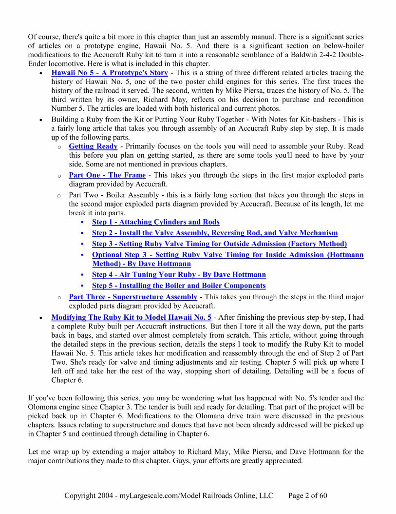

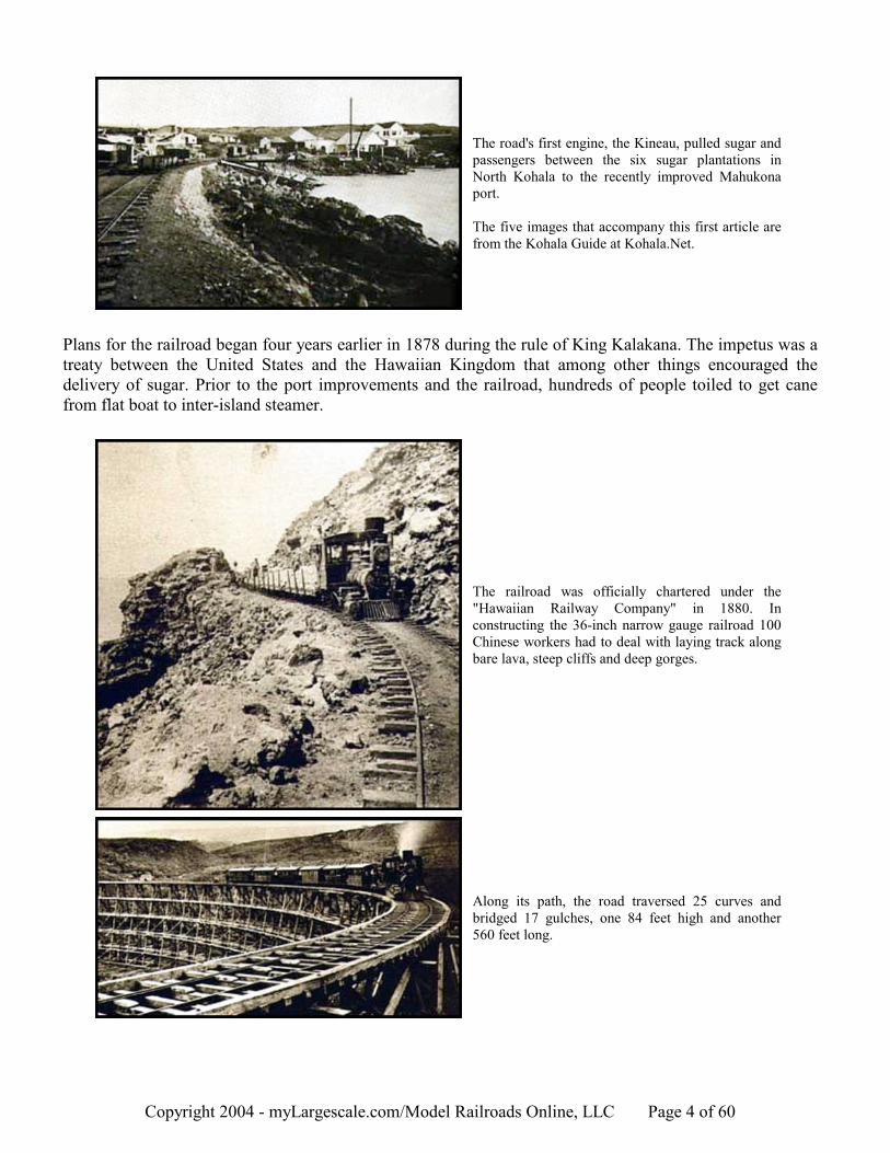
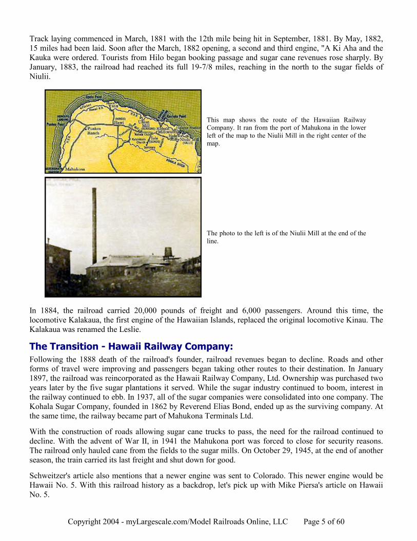
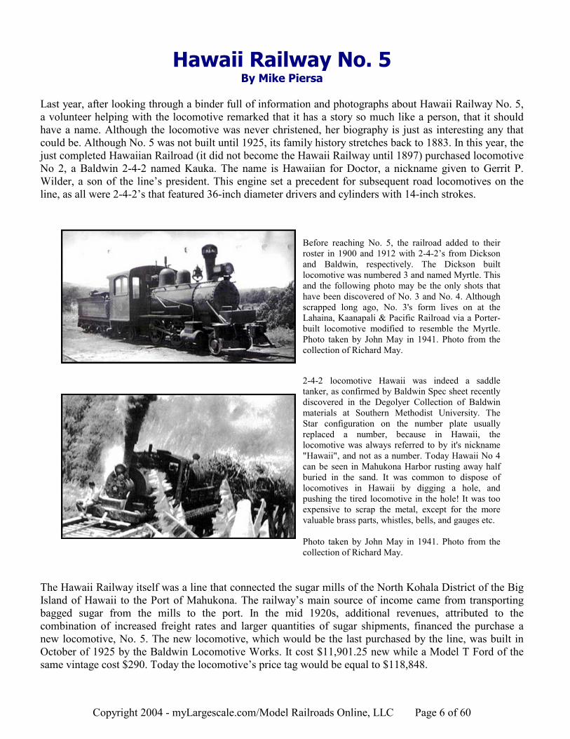

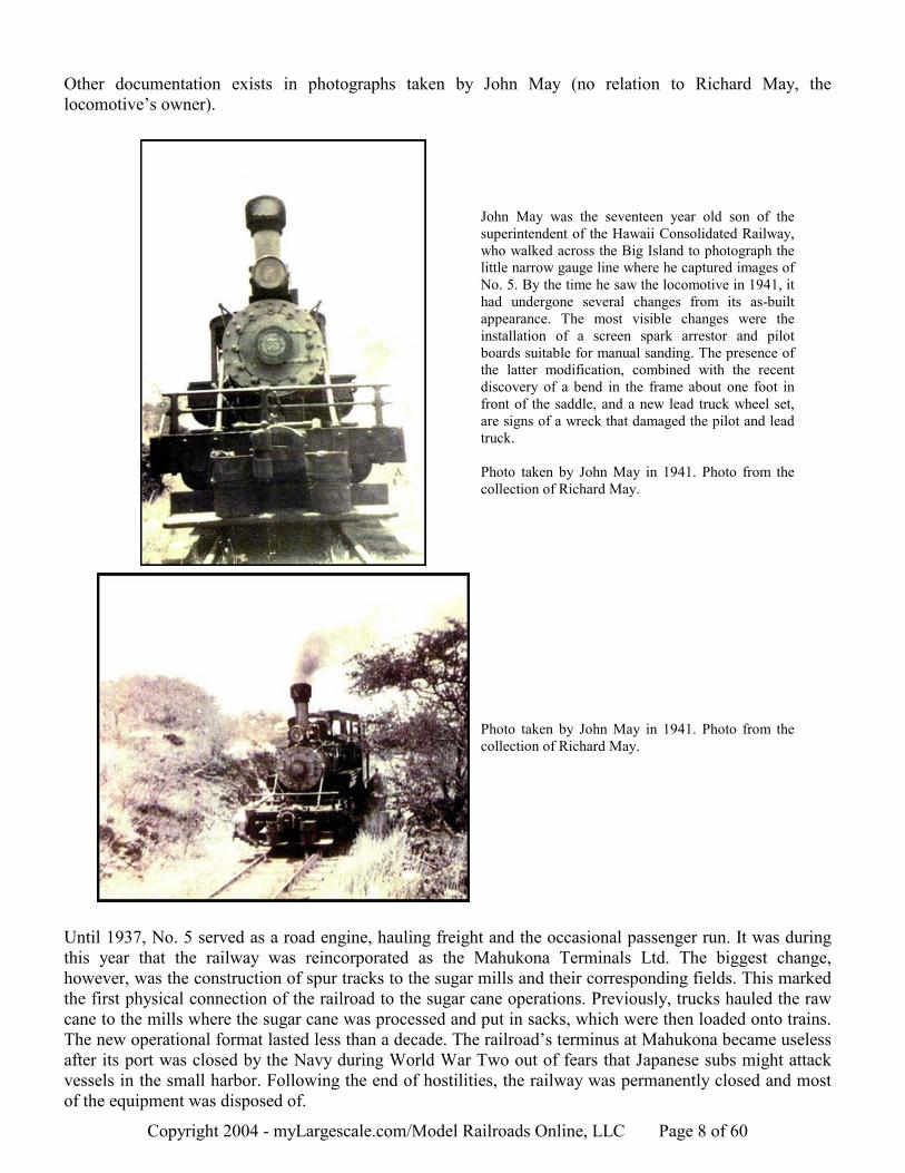
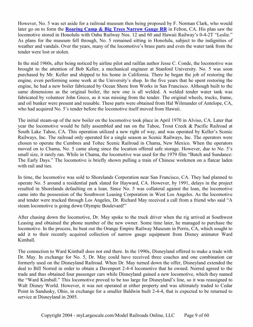

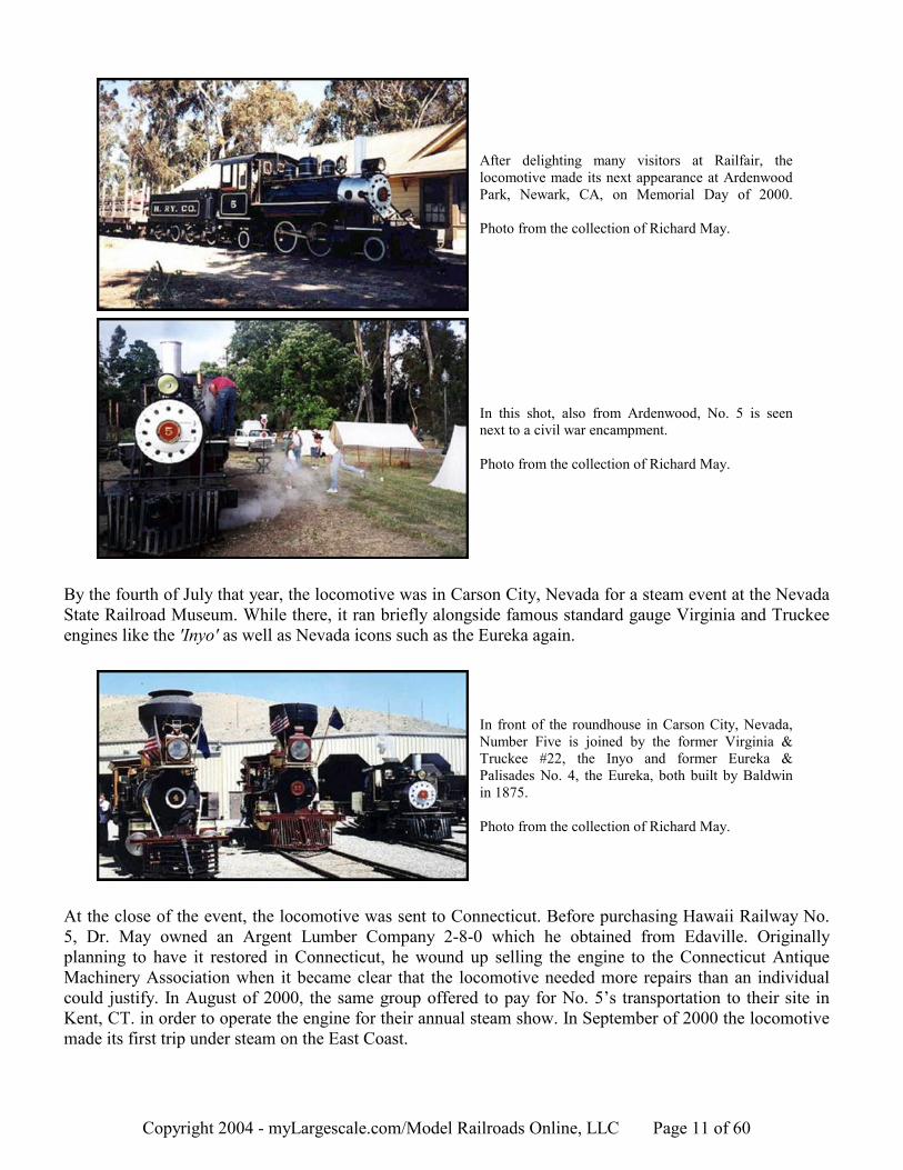
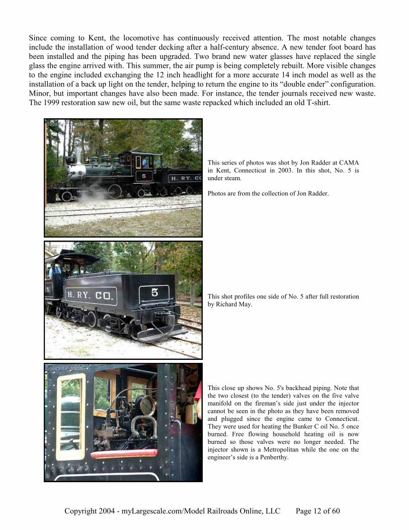
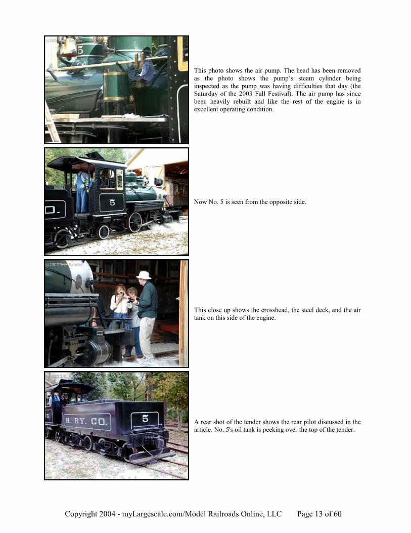

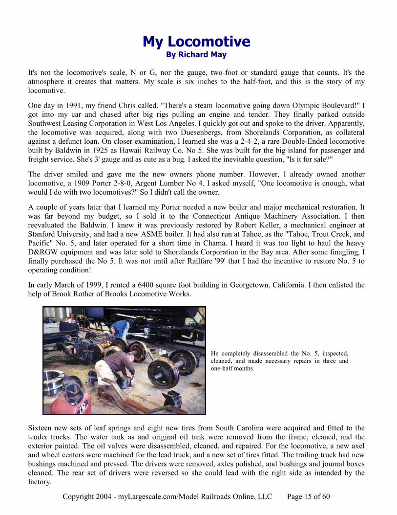
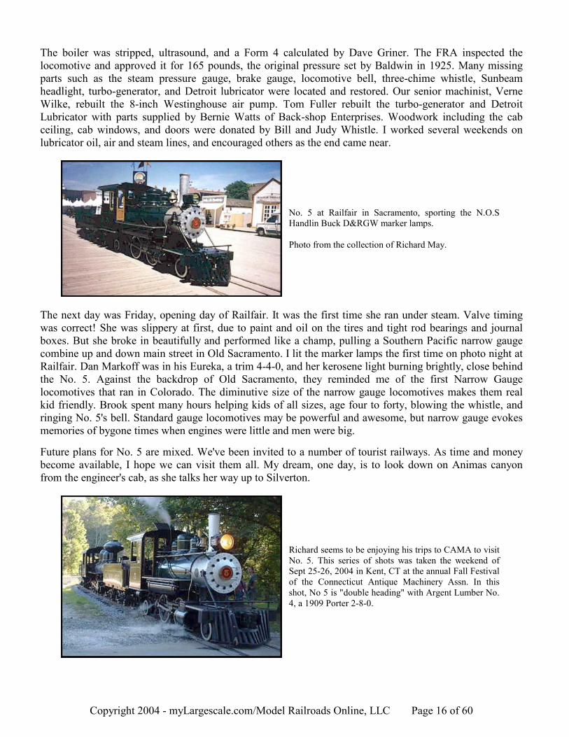
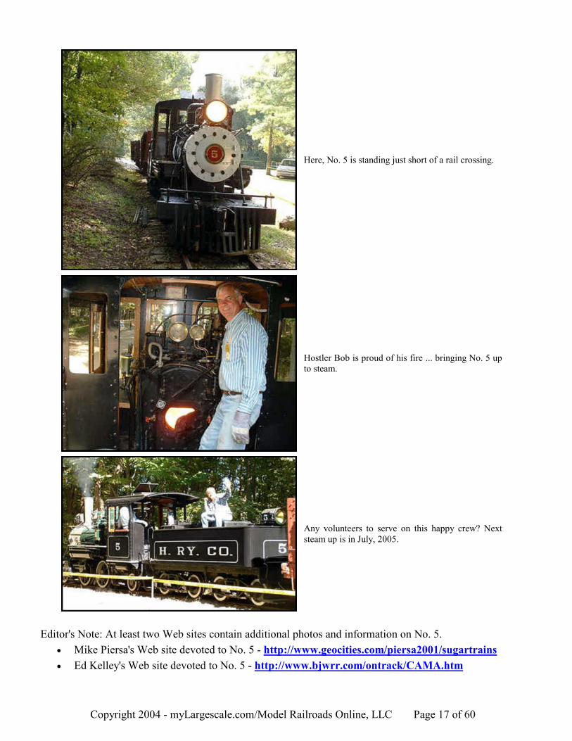
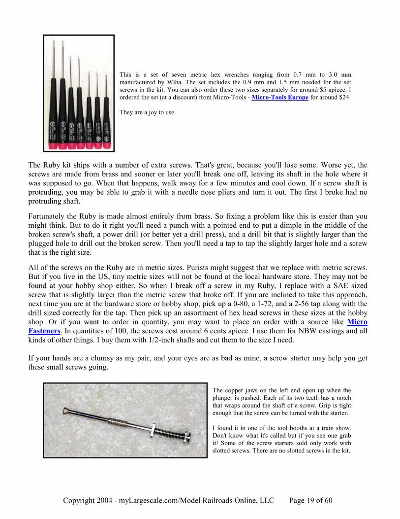


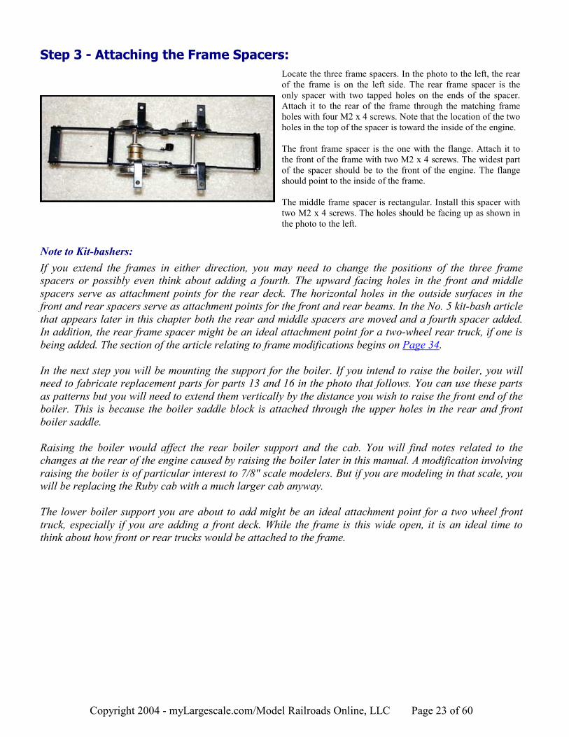
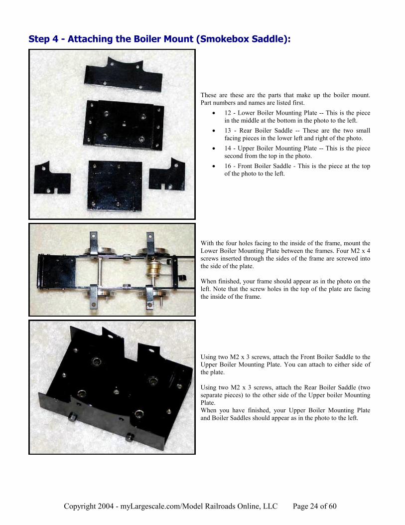

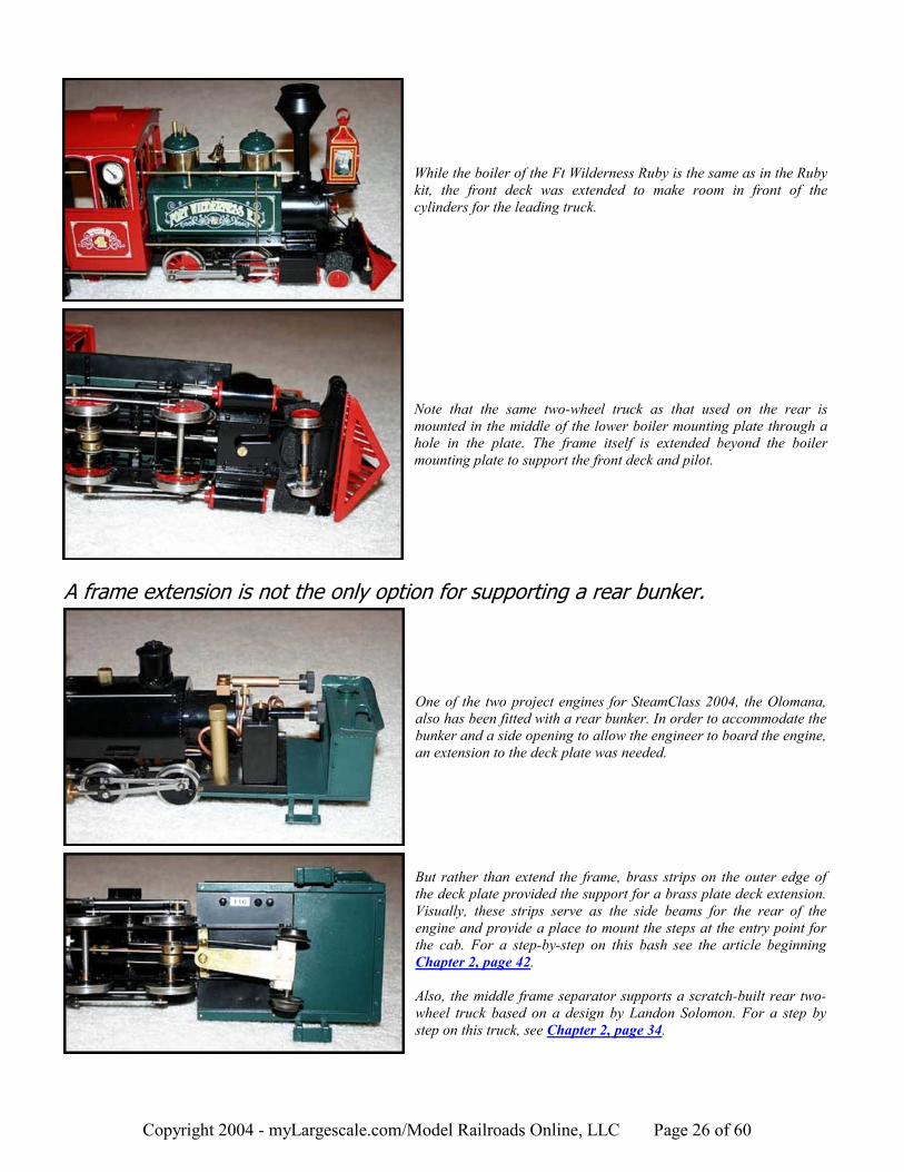

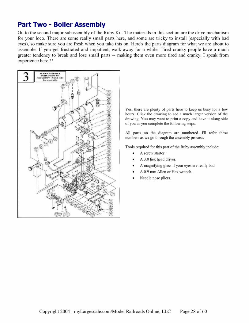


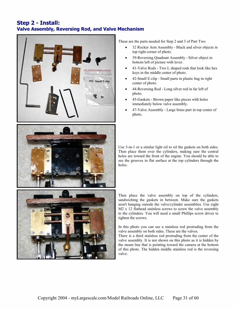


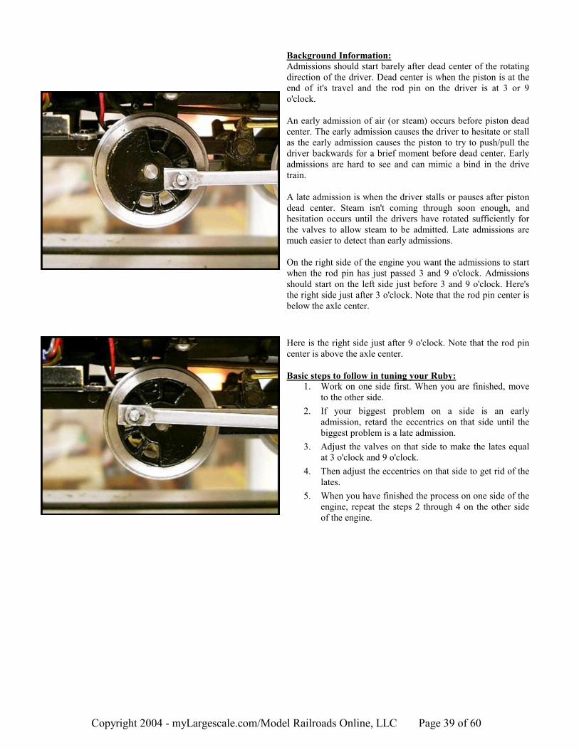


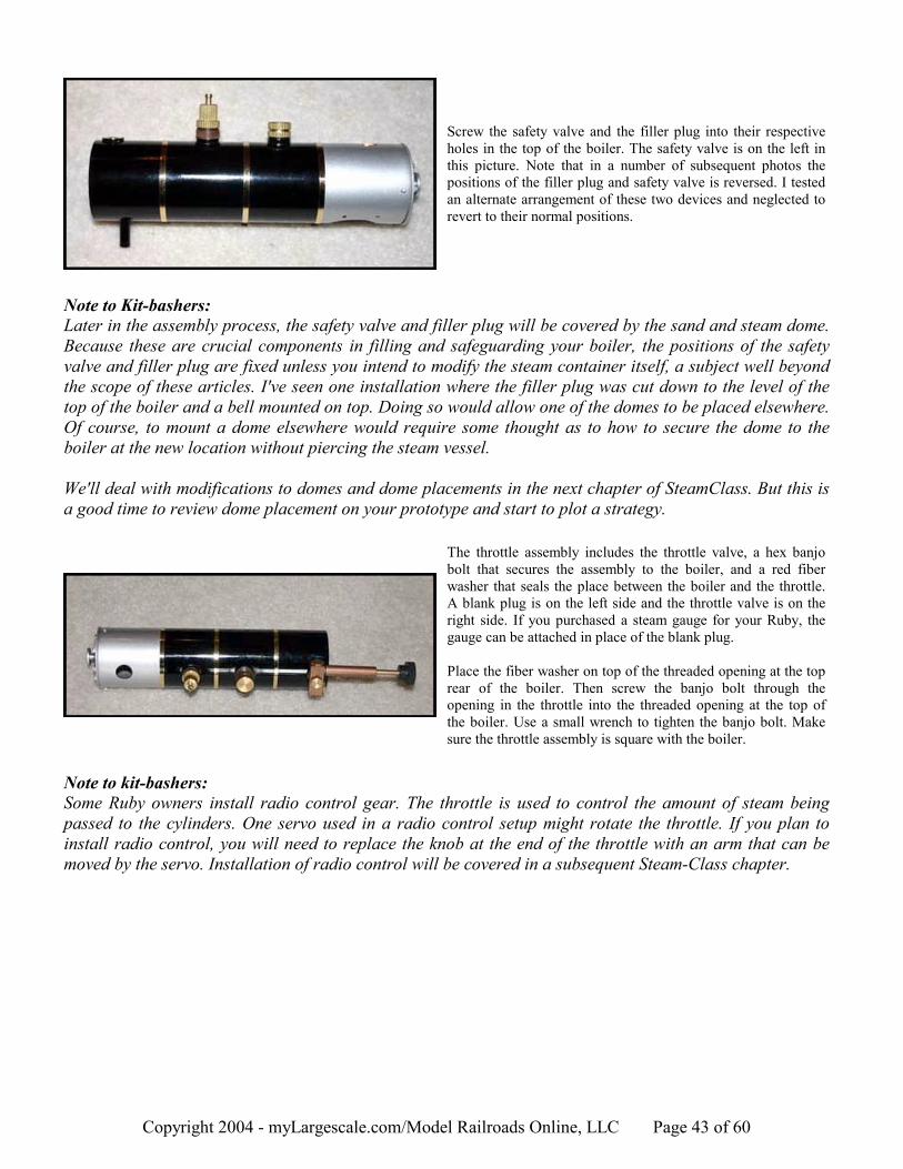


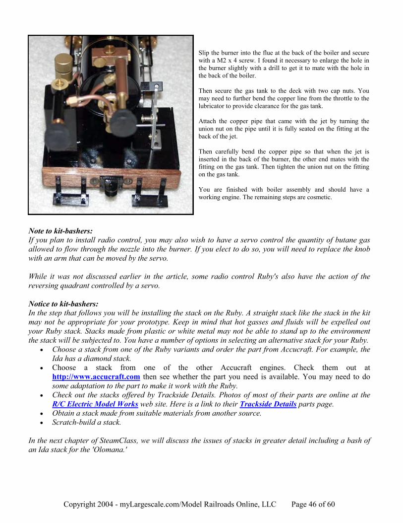


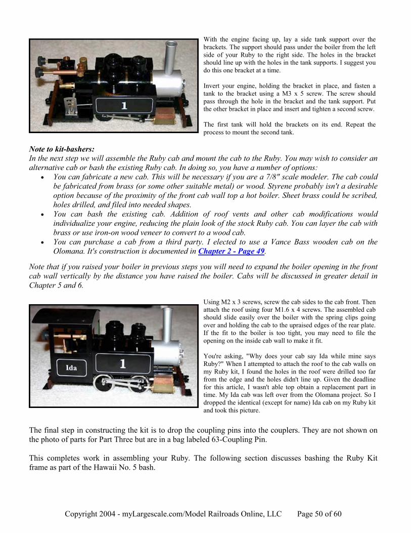


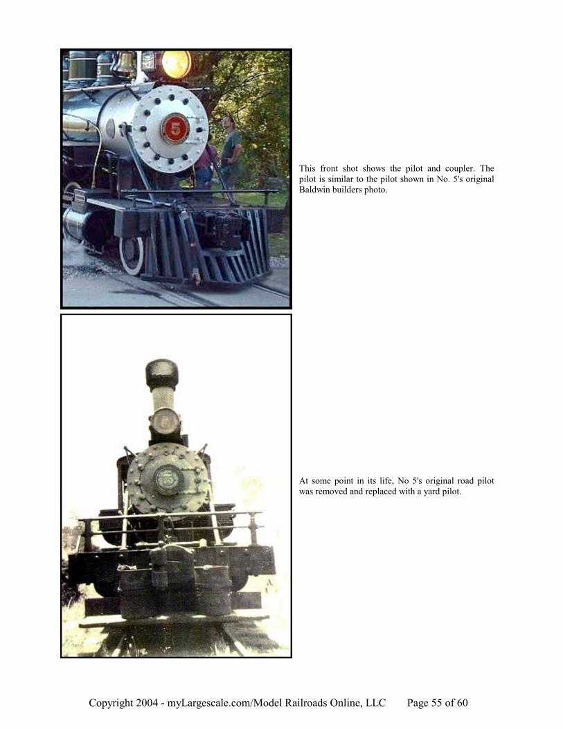
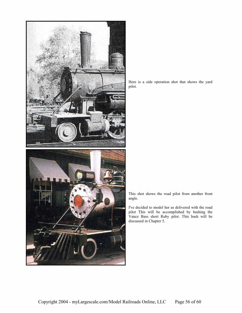
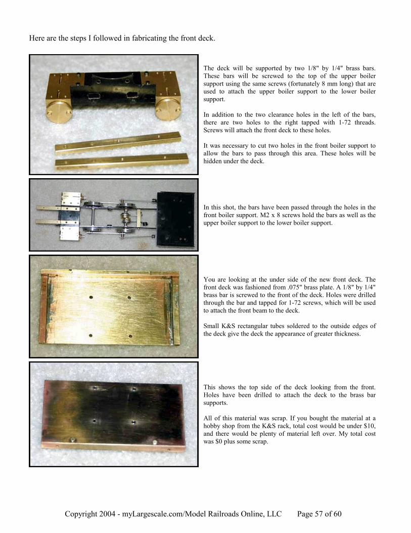
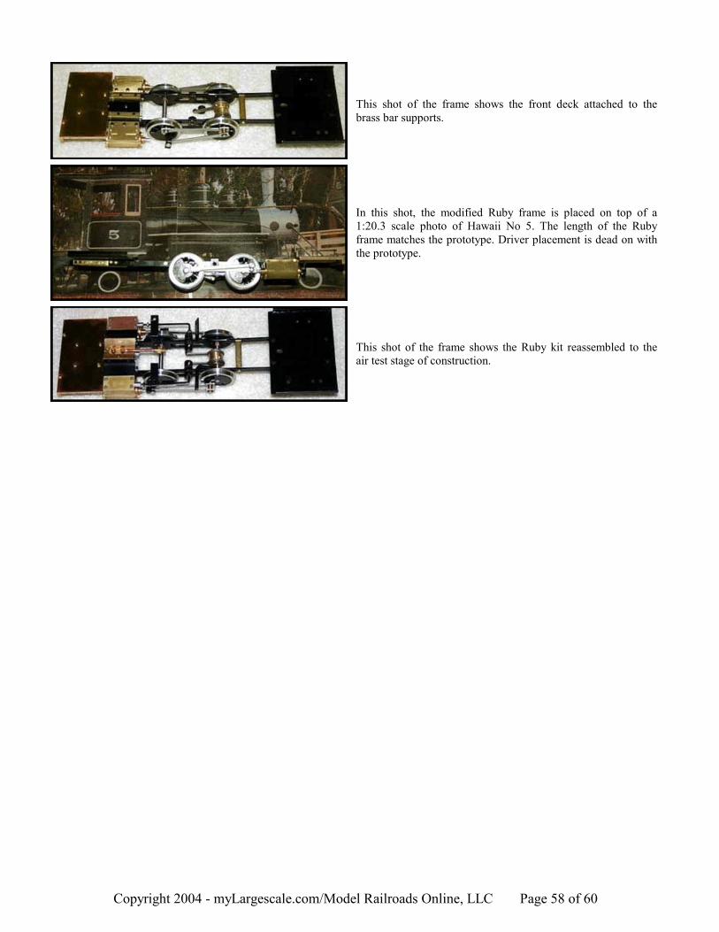


![Ruby on Rails [ Ruby On Rails.ppt ] - [Ruby - [Ruby-Doc.org ...](https://static.documents.pub/doc/80x56/5491e450b479597e6a8b57d5/ruby-on-rails-ruby-on-railsppt-ruby-ruby-docorg-.jpg)


