SW Development Kit Description MLX81200 BLDC Motor Controller MLX81200 SW Development kit Page 1/39 Rev 1.4 / 05/11/08 Author: ERE Table of contents 1. Introduction ..........................................................................................................................................2 2. Contents of the MLX81200 SW Development kit ...............................................................................3 2.1. Hardware .....................................................................................................................................................3 2.2. Software .......................................................................................................................................................5 3. How to use the MLX81200 SW Development kit ................................................................................6 4. The Software Kit...................................................................................................................................7 4.1. Software Evaluation flow ...........................................................................................................................7 4.2. The installation of the Software Kit ..........................................................................................................9 5. Hardware Kit ......................................................................................................................................11 5.1. Configuration ............................................................................................................................................11 5.2. General .......................................................................................................................................................12 5.3. Evaluation board.......................................................................................................................................12 6. Quick start up .....................................................................................................................................18 6.1. Using the C flow ........................................................................................................................................18 6.2. Programming a HEX file to the FLASH.................................................................................................20 7. MLX81200 Software configuration tool (SCT) ................................................................................23 7.1. General .......................................................................................................................................................23 7.2. Locate the demokit firmware sources and load the configuration .......................................................24 7.3. Configure the demokit firmware .............................................................................................................25 7.4. Save, compile and flash the firmware .....................................................................................................27 8. BLDC DemoKit PC program .............................................................................................................30 8.1. General .......................................................................................................................................................30 8.2. Main window .............................................................................................................................................31 8.3. Control Load window ...............................................................................................................................33 8.4. Control Debug window.............................................................................................................................34 8.5. PID controller and PC program ..............................................................................................................34 9. Appendix .............................................................................................................................................35 9.1. Schematics of the Evaluation Board........................................................................................................35 9.2. Schematic of the Evaluation Board – Part 2 Programmer Interface ...................................................36 9.3. Schematic of the Power Board .................................................................................................................37 10. History record ...................................................................................................................................38 11. Disclaimer.........................................................................................................................................39
Transcript
SW Development Kit Description MLX81200
BLDC Motor Controller
MLX81200 SW Development kit Page 1/39 Rev 1.4 / 05/11/08 Author: ERE
3. How to use the MLX81200 SW Development kit................................................................................6
4. The Software Kit...................................................................................................................................7
6. Quick start up .....................................................................................................................................18
6.1. Using the C flow ........................................................................................................................................18
6.2. Programming a HEX file to the FLASH.................................................................................................20
8.2. Main window.............................................................................................................................................31
8.3. Control Load window...............................................................................................................................33
8.4. Control Debug window.............................................................................................................................34
8.5. PID controller and PC program..............................................................................................................34
9.1. Schematics of the Evaluation Board........................................................................................................35
9.2. Schematic of the Evaluation Board – Part 2 Programmer Interface...................................................36
9.3. Schematic of the Power Board.................................................................................................................37
10. History record...................................................................................................................................38
MLX81200 SW Development kit Page 2/39 Rev 1.4 / 05/11/08 Author: ERE
1. Introduction This document is intended to give a brief introduction of the different parts of the SW Development kit for the ASSP MLX81200. The aim of this document is to support a fast start up with this kit. Besides this document, several other important documents are necessary for a deeper understanding of more detailed development issues. The most important documents related to the MLX81200 are: MLX81200 Datasheet -detailed description of the chip with all functions and features MLX82001_Product_Specification -MelexCM Datasheet and underlying documentation of different blocks included in the MLX82001 Melexis development system -MLX Assembler, Linker, Obgen, Tabgen description GNU C-Compiler GCC -GCC User’s Manual, incl. AS, LD and Getting Started Doc Melexis emulator (flash programming SW) -description of the Emulator Melexis emulator SW Mlx16 C-Debugger -Debugger User’s Manual Mlx16 CPU Simulator -description of the Simulator Mlx16X8 Data book -explanation of the Mlx16X8 microcontroller core and the instruction set Melexis Lin Master documentation -description of the Melexis USB LIN Master MelexCM LIN API (including required SW files) -detailed description of the MelexCM LIN API MLX81200 BLDC Demo Kit firmware -MLX81200_SWDesignDescription_x.pdf AppNote_MLX81100_MLX81200_Reflashing_on_module_x.pdf ApplNote_Flash_over_pin_LIN_x.pdf
SW Development Kit Description MLX81200
BLDC Motor Controller
MLX81200 SW Development kit Page 3/39 Rev 1.4 / 05/11/08 Author: ERE
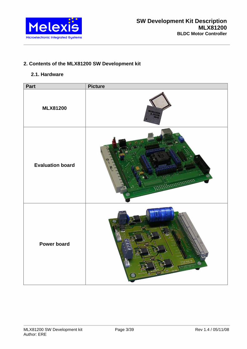
2. Contents of the MLX81200 SW Development kit
2.1. Hardware Part Picture
MLX81200
Evaluation board
Power board
SW Development Kit Description MLX81200
BLDC Motor Controller
MLX81200 SW Development kit Page 4/39 Rev 1.4 / 05/11/08 Author: ERE
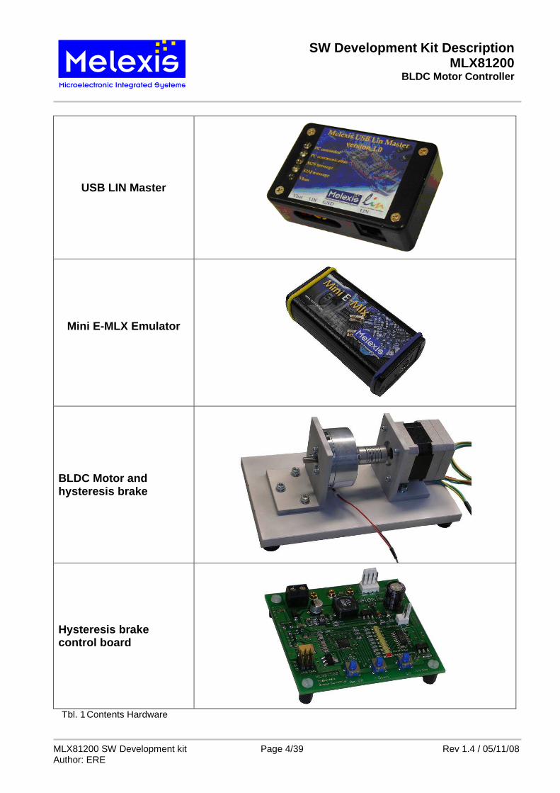
USB LIN Master
Mini E-MLX Emulator
BLDC Motor and hysteresis brake
Hysteresis brake control board
Tbl. 1 Contents Hardware
SW Development Kit Description MLX81200
BLDC Motor Controller
MLX81200 SW Development kit Page 5/39 Rev 1.4 / 05/11/08 Author: ERE
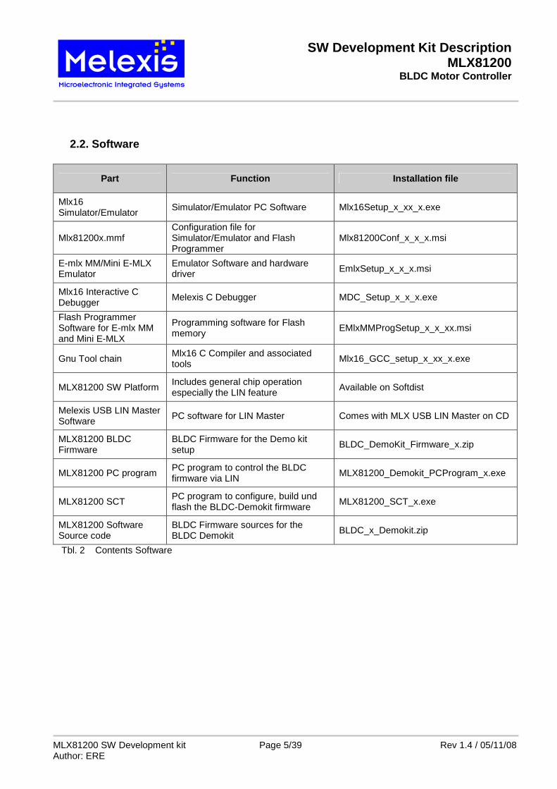
2.2. Software
Part Function Installation file
Mlx16 Simulator/Emulator
Simulator/Emulator PC Software Mlx16Setup_x_xx_x.exe
Mlx81200x.mmf Configuration file for Simulator/Emulator and Flash Programmer
Mlx81200Conf_x_x_x.msi
E-mlx MM/Mini E-MLX Emulator
Emulator Software and hardware driver EmlxSetup_x_x_x.msi
Mlx16 Interactive C Debugger
Melexis C Debugger MDC_Setup_x_x_x.exe
Flash Programmer Software for E-mlx MM and Mini E-MLX
Programming software for Flash memory
EMlxMMProgSetup_x_x_xx.msi
Gnu Tool chain Mlx16 C Compiler and associated tools Mlx16_GCC_setup_x_xx_x.exe
MLX81200 SW Platform Includes general chip operation especially the LIN feature
Available on Softdist
Melexis USB LIN Master Software
PC software for LIN Master Comes with MLX USB LIN Master on CD
MLX81200 BLDC Firmware
BLDC Firmware for the Demo kit setup
BLDC_DemoKit_Firmware_x.zip
MLX81200 PC program PC program to control the BLDC firmware via LIN
MLX81200_Demokit_PCProgram_x.exe
MLX81200 SCT PC program to configure, build und flash the BLDC-Demokit firmware
MLX81200_SCT_x.exe
MLX81200 Software Source code
BLDC Firmware sources for the BLDC Demokit BLDC_x_Demokit.zip
Tbl. 2 Contents Software
SW Development Kit Description MLX81200
BLDC Motor Controller
MLX81200 SW Development kit Page 6/39 Rev 1.4 / 05/11/08 Author: ERE
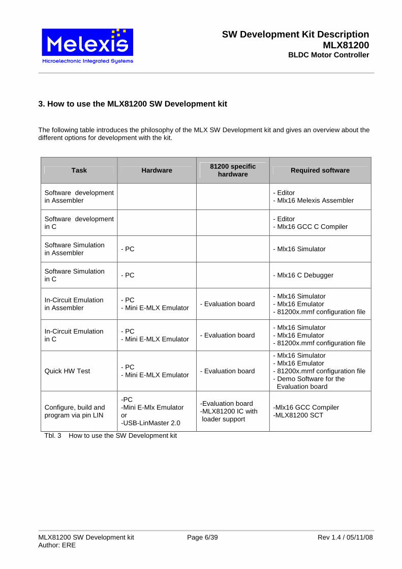
3. How to use the MLX81200 SW Development kit The following table introduces the philosophy of the MLX SW Development kit and gives an overview about the different options for development with the kit.
Task Hardware 81200 specific hardware Required software
- Mlx16 Simulator - Mlx16 Emulator - 81200x.mmf configuration file - Demo Software for the Evaluation board
Configure, build and program via pin LIN
-PC -Mini E-Mlx Emulator or -USB-LinMaster 2.0
-Evaluation board -MLX81200 IC with loader support
-Mlx16 GCC Compiler -MLX81200 SCT
Tbl. 3 How to use the SW Development kit
SW Development Kit Description MLX81200
BLDC Motor Controller
MLX81200 SW Development kit Page 7/39 Rev 1.4 / 05/11/08 Author: ERE
4. The Software Kit
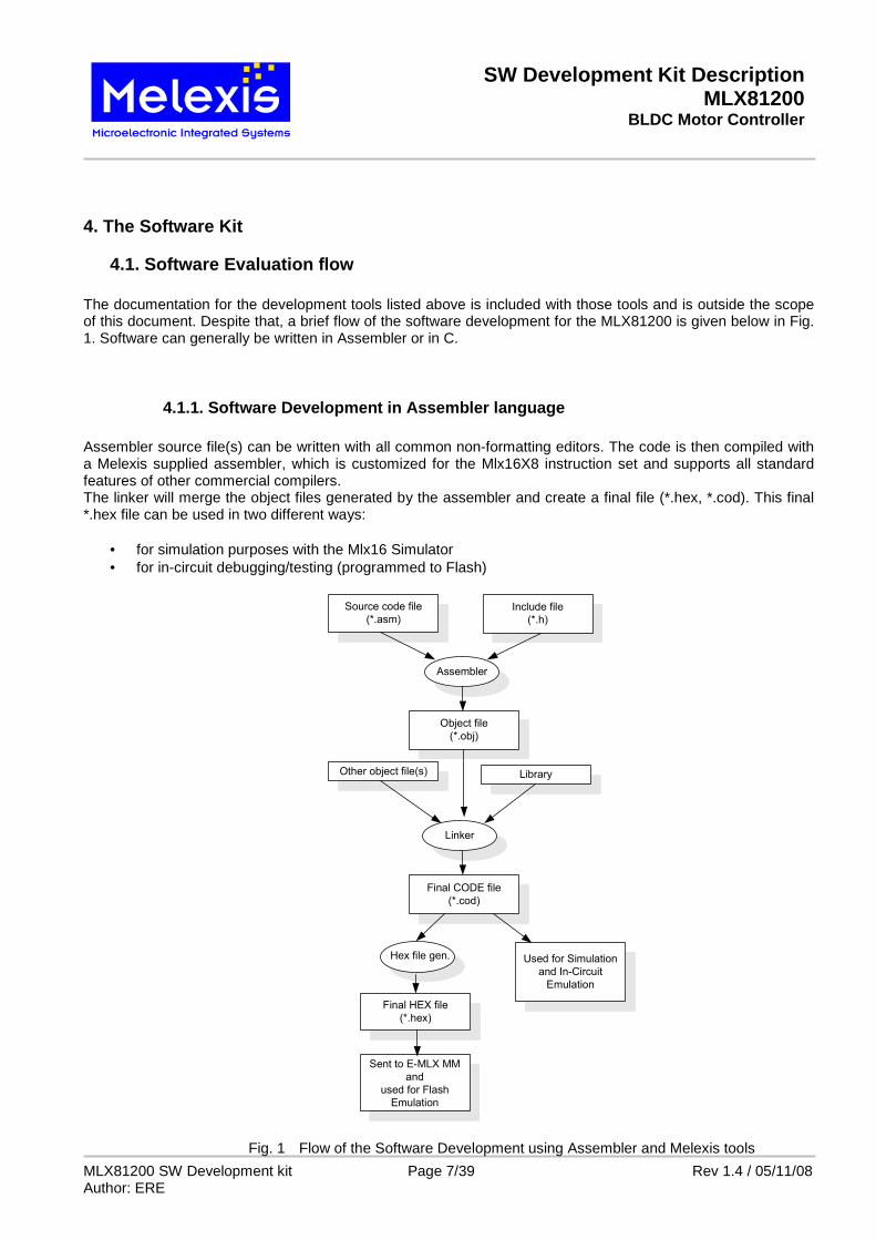
4.1. Software Evaluation flow The documentation for the development tools listed above is included with those tools and is outside the scope of this document. Despite that, a brief flow of the software development for the MLX81200 is given below in Fig. 1. Software can generally be written in Assembler or in C.
4.1.1. Software Development in Assembler language Assembler source file(s) can be written with all common non-formatting editors. The code is then compiled with a Melexis supplied assembler, which is customized for the Mlx16X8 instruction set and supports all standard features of other commercial compilers. The linker will merge the object files generated by the assembler and create a final file (*.hex, *.cod). This final *.hex file can be used in two different ways:
• for simulation purposes with the Mlx16 Simulator • for in-circuit debugging/testing (programmed to Flash)
Source code file
(*.asm)Include file
(*.h)
Assembler
Object file
(*.obj)
Linker
Other object file(s) Library
Final CODE file
(*.cod)
Hex file gen.
Sent to E-MLX MM
and
used for Flash
Emulation
Used for Simulation
and In-Circuit
Emulation
Final HEX file
(*.hex)
Fig. 1 Flow of the Software Development using Assembler and Melexis tools
SW Development Kit Description MLX81200
BLDC Motor Controller
MLX81200 SW Development kit Page 8/39 Rev 1.4 / 05/11/08 Author: ERE
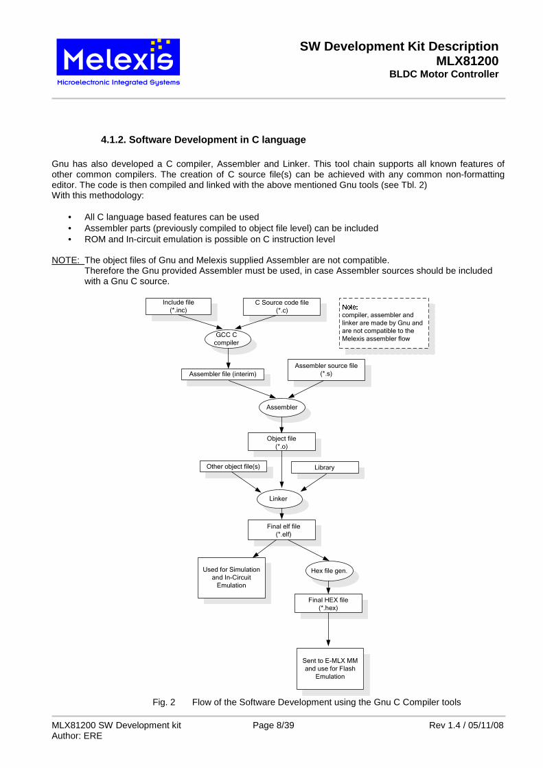
4.1.2. Software Development in C language Gnu has also developed a C compiler, Assembler and Linker. This tool chain supports all known features of other common compilers. The creation of C source file(s) can be achieved with any common non-formatting editor. The code is then compiled and linked with the above mentioned Gnu tools (see Tbl. 2) With this methodology:
• All C language based features can be used • Assembler parts (previously compiled to object file level) can be included • ROM and In-circuit emulation is possible on C instruction level
NOTE: The object files of Gnu and Melexis supplied Assembler are not compatible. Therefore the Gnu provided Assembler must be used, in case Assembler sources should be included with a Gnu C source.
Final elf file
(*.elf)
Hex file gen.Used for Simulation
and In-Circuit
Emulation
Final HEX file
(*.hex)
Sent to E-MLX MM
and use for Flash
Emulation
C Source code file
(*.c)
Include file
(*.inc)
GCC C
compiler
Object file
(*.o)
Linker
Other object file(s) Library
Assembler
Assembler file (interim)
Assembler source file
(*.s)
compiler, assembler and
linker are made by Gnu and
are not compatible to the
Melexis assembler flow
Fig. 2 Flow of the Software Development using the Gnu C Compiler tools
SW Development Kit Description MLX81200
BLDC Motor Controller
MLX81200 SW Development kit Page 9/39 Rev 1.4 / 05/11/08 Author: ERE
4.2. The installation of the Software Kit
4.2.1. Installation of the tools All tools run under WinXP®. Win9x, WinNT® and Win2000® are not supported. All programs use the standard windows installer of WinXP®. The following tools have to be installed:
• EmlxSetup_x_x_x.msi Emulator Software and hardware driver • Mlx16Setup_x_xx_x.exe Mlx16 Simulator Software • MDC_Setup_x_x_x.exe Mlx16 Interactive Debugger • EMlxMMProgSetup_x_x_xx.msi Flash Programmer Software • Mlx81200Conf_x_x_x.msi Configuration file, consists of chip specific settings • Mlx16_GCC_setup_x_xx_x.exe Mlx16 C Compiler • MLXLinMaster_Setup.exe USB LIN Master Software • MlxLinDebug.exe Melexis USB LIN Master • MLX81200_Demokit_PCProgram_x.exe PC program to control the BLDC firmware via LIN • MLX81200_SCT_x.exe PC program to configure, build und flash the BLDC- Demokit firmware
x – Revision number Demo Software can be copied at any top level directory:
• Software_Platform_MelexCM_x_x_x.zip Software platform including the Demo Software • BLDC_DemoKit_Firmware_x_x.zip firmware for the Evaluation setup • BLDC_x_Demokit.zip the source code of the BLDC DemoKit firmware
4.2.2. Directory structure of the Software Tools It is recommended to use the “standard” installation option. After installing with this installation option, the following path settings and directory structure appears: C:\Programs\Melexis\ E-Mlx MM\Programmer FLASH Programmer Software Bin MLX Assembler Package Bin\Doc MLX Assembler Development System Documentation Emulator Emulator Software and help file Simulator MLX16 Simulator/Emulator (Assembler) MDC MLX16 Interactive C Debugger and manual MLX81200_DemoKit_PCprogram MLX81200 Control Software
SW Development Kit Description MLX81200
BLDC Motor Controller
MLX81200 SW Development kit Page 10/39 Rev 1.4 / 05/11/08 Author: ERE
The release of Mx16 GCC suite installs in the following directory tree: C:\mlx16-gcc\
bin contains executable files. Lib contains libgcc library and include files and compiler specs. mlx16 contains libmlx16 library and include files; start-up module;
linker command files and memory map. libexec additional executable files. config configuration file and script for Mlx16 Simulator. docs documentation. examples sample programs.
81200.mmf Configuration file for Simulator, Emulator and Flash Programmer
C:\Programme\LIN Commander\LinCommander.exe LinCommander.exe a sample interface program that can be used to debug via the LIN bus when developing an application.
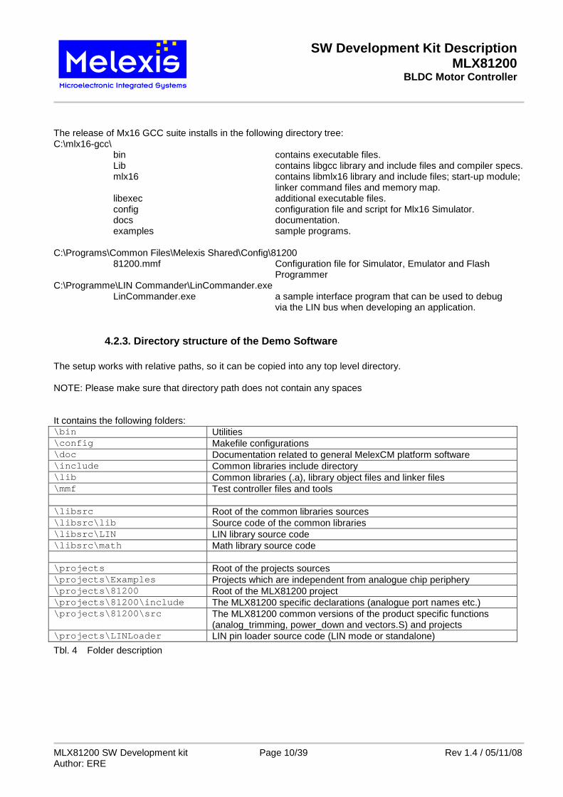
4.2.3. Directory structure of the Demo Software The setup works with relative paths, so it can be copied into any top level directory. NOTE: Please make sure that directory path does not contain any spaces It contains the following folders: \bin Utilities \config Makefile configurations \doc Documentation related to general MelexCM platform software \include Common libraries include directory \lib Common libraries (.a), library object files and linker files \mmf Test controller files and tools \libsrc Root of the common libraries sources \libsrc\lib Source code of the common libraries \libsrc\LIN LIN library source code \libsrc\math Math library source code \projects Root of the projects sources \projects\Examples Projects which are independent from analogue chip periphery \projects\81200 Root of the MLX81200 project \projects\81200\include The MLX81200 specific declarations (analogue port names etc.) \projects\81200\src The MLX81200 common versions of the product specific functions
(analog_trimming, power_down and vectors.S) and projects \projects\LINLoader LIN pin loader source code (LIN mode or standalone)
Tbl. 4 Folder description
SW Development Kit Description MLX81200
BLDC Motor Controller
MLX81200 SW Development kit Page 11/39 Rev 1.4 / 05/11/08 Author: ERE
5. Hardware Kit
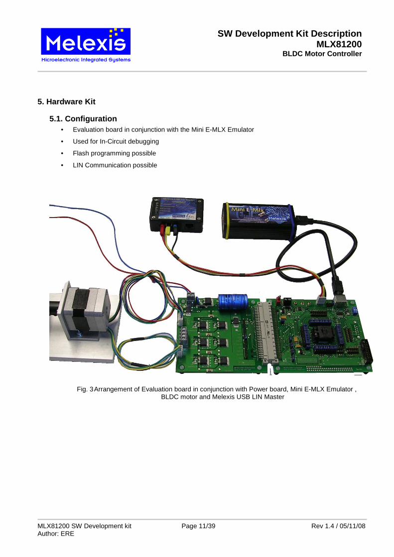
5.1. Configuration • Evaluation board in conjunction with the Mini E-MLX Emulator
• Used for In-Circuit debugging
• Flash programming possible
• LIN Communication possible
Fig. 3 Arrangement of Evaluation board in conjunction with Power board, Mini E-MLX Emulator , BLDC motor and Melexis USB LIN Master
SW Development Kit Description MLX81200
BLDC Motor Controller
MLX81200 SW Development kit Page 12/39 Rev 1.4 / 05/11/08 Author: ERE
5.2. General The purpose of the HW kit is the development of software for the MLX81200 BLDC Motor Controller. Using this HW kit, the device can be evaluated in a detailed fashion. The evaluation system is composed of an evaluation board and the power board. The idea of the evaluation system is to have two stand-alone boards:
• A standard board (evaluation board) is used for all possible applications. It consists of a socket for the chip, several pin headers for all signals from the chip and interface connectors to the Emulator, LIN-Bus and the application board (power board).
• A customized application board (power board) has to be designed specifically for a certain application by the user. It is possible to connect this power board on 32-pin connector. The sample power board consists of 3 half Bridges with N-FET-transistors, 2 shunts for possible current supervision and interface connectors to Vbat and the BLDC-Motor.
5.3. Evaluation board
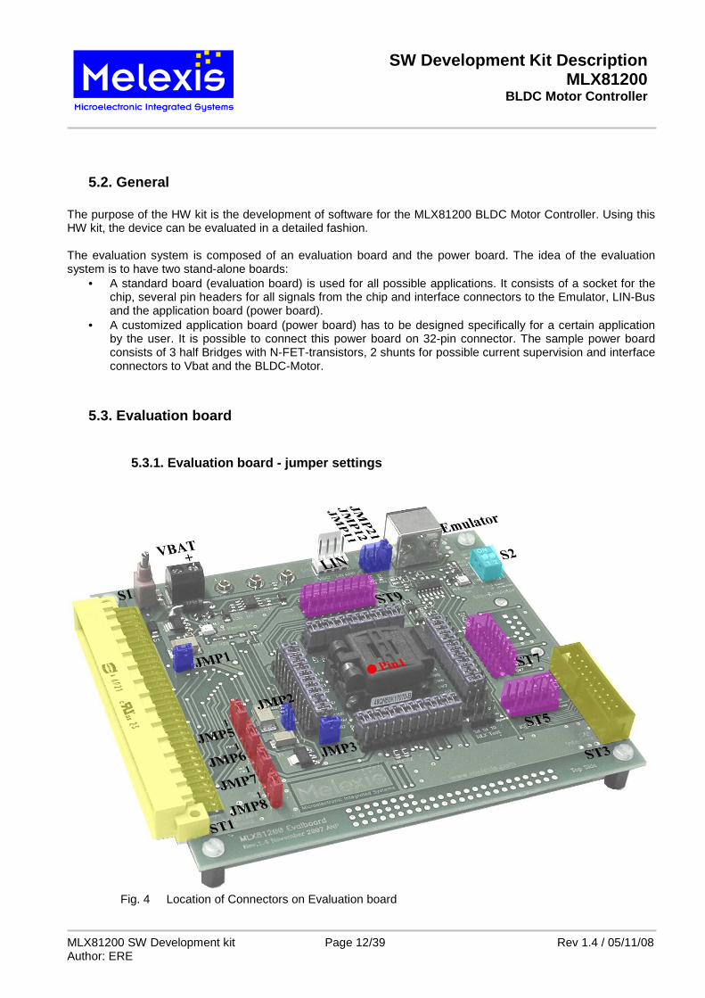
5.3.1. Evaluation board - jumper settings
Fig. 4 Location of Connectors on Evaluation board
SW Development Kit Description MLX81200
BLDC Motor Controller
MLX81200 SW Development kit Page 13/39 Rev 1.4 / 05/11/08 Author: ERE
JMP1 short : connects Vbat to the chip. open : disconnects Vbat from the chip JMP2 short : connects CWD-pin to GND open : CWD-pin of the chip is active. NOTE: the external capacitor for analog Watchdog is active. JMP3 short : disables the external regulator NPN transistor for higher VCC loads. open : enables the external regulator NPN transistor for higher VCC loads JMP5 1-2 : enable low pass filter R55/C15 and voltage divider R5/R50 for pin T 2-3 : enable only the voltage divider R5/R50 for pin T JMP6 1-2 : enable low pass filter R66/C16 and voltage divider R6/R60 for pin SW5
2-3 : enable only the voltage divider R6/R60 for pin SW5 JMP7 1-2 : enable low pass filter R77/C17 and voltage divider R7/R70 for pin SW6 2-3 : enable only the voltage divider R7/R70 for pin SW6 JMP8 1-2 : enable low pass filter R88/C18 and voltage divider R8/R80 for pin SW7 2-3 : enable only the voltage divider R8/R80 for pin SW7 S2 consists of the jumper JMP9 and JMP10: JMP9 short : the connection between the chip and the emulator is split
open : the connection between the chip and the emulator is established, the chip can be accessed by the emulator, if the emulator is not plugged the CPU is executing the flash program
JMP10 short : CPU does not execute the flash program open : CPU is executing the flash program, if no emulator is connected and JMP9 is shorted JMP11 short : the pull up resistors R21 and R22 are connected to the test interface inputs +JMP12 (necessary if the E-mlx MM programmer is used)
open : the pull up resistors are disconnected (default for the Mini E-Mlx programmer) JMP21 short : supply the additional voltage regulators inside the Mini E-Mlx programmer (required) open :disconnect VBAT from the test interface (required for the E-mlx MM programmer)
NOTE: If the E-Mlx MM programmer is connected and the JMP21 is shorted the diode D4 can be destroyed.
5.3.2. Functionality of the Evaluation Board Main Power Switch S1 selects between supply connector of the evaluation board or the supply connector of the power board. IMPORTANT: If the evaluation board is supplied via the power board, the power supply connector of the Evaluation board should NOT be connected! Otherwise the board or the power supply will be damaged! The PCB only requires a DC voltage of +12…+18V which is applied via the supply connector of the evaluation board. This is valid if the evaluation board is used stand-alone without the power board. In case the board is used alongside the power board, the power board delivers the supply voltage for both PCBs. Both the evaluation board and the power board are protected against reverse polarity.
SW Development Kit Description MLX81200
BLDC Motor Controller
MLX81200 SW Development kit Page 14/39 Rev 1.4 / 05/11/08 Author: ERE
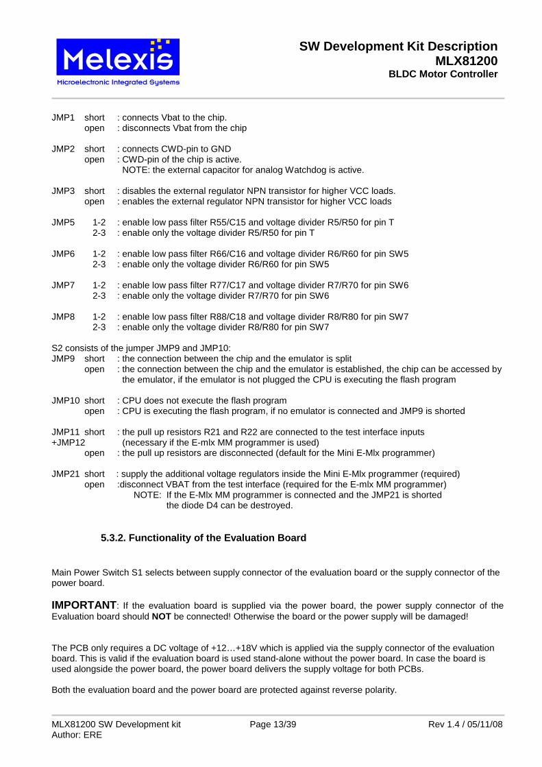
5.3.3. Evaluation board – Phase signal filters
Fig. 5 Position of the filter components on the EVB
The resistors R13, R14, R15 and the diodes D13, D14, D15 protect the IC against negative current and voltage from the motor coils. The resistors are increase the discharging time of the high side n-channel MOSFET transistor gates. The phase signals on the T, SW5, SW6 and SW7 pins can be reduced with the voltage dividers R5/R50, R6/R60, R7/R70 and R8/R80. With the low pass filters R55/C15, R66/C16, R77/C17 and R88/C18 fast disturbances can be filtered out. The default value for the resistor is 150 ohm and for the capacitor is 10nF.
C17
R77
C18
D14
R55
D13
R88
D15
R5
R6
R7
R8
R80
R66
C16
R15
R70
R50
R14
R60
R13
C15
SW Development Kit Description MLX81200
BLDC Motor Controller
MLX81200 SW Development kit Page 15/39 Rev 1.4 / 05/11/08 Author: ERE
5.3.4. Evaluation board - Jumper ring
The jumper ring enables the user to either connect or disconnect all signal lines to the chip. By removing jumpers, the circuit from the chip to the application hardware can be disconnected e.g. for measuring current or applying external signals. All jumpers are described with the specific pin names on the board.
5.3.5. Connection between Power Board Port and Eval uation Board
MLX81200 SW Development kit Page 16/39 Rev 1.4 / 05/11/08 Author: ERE
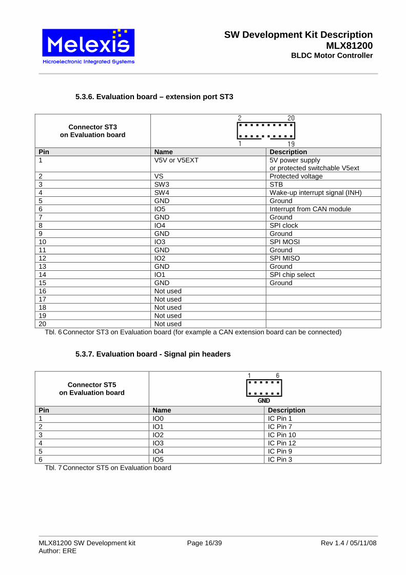
5.3.6. Evaluation board – extension port ST3
Connector ST3 on Evaluation board
Pin Name Description 1 V5V or V5EXT 5V power supply
or protected switchable V5ext 2 VS Protected voltage 3 SW3 STB 4 SW4 Wake-up interrupt signal (INH) 5 GND Ground 6 IO5 Interrupt from CAN module 7 GND Ground 8 IO4 SPI clock 9 GND Ground 10 IO3 SPI MOSI 11 GND Ground 12 IO2 SPI MISO 13 GND Ground 14 IO1 SPI chip select 15 GND Ground 16 Not used 17 Not used 18 Not used 19 Not used 20 Not used
Tbl. 6 Connector ST3 on Evaluation board (for example a CAN extension board can be connected)
5.3.7. Evaluation board - Signal pin headers
Connector ST5 on Evaluation board
Pin Name Description 1 IO0 IC Pin 1 2 IO1 IC Pin 7 3 IO2 IC Pin 10 4 IO3 IC Pin 12 5 IO4 IC Pin 9 6 IO5 IC Pin 3
Tbl. 7 Connector ST5 on Evaluation board
SW Development Kit Description MLX81200
BLDC Motor Controller
MLX81200 SW Development kit Page 17/39 Rev 1.4 / 05/11/08 Author: ERE
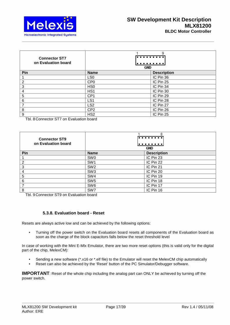
Connector ST7 on Evaluation board
Pin Name Description 1 LS0 IC Pin 36 2 CP0 IC Pin 25 3 HS0 IC Pin 34 4 HS1 IC Pin 30 5 CP1 IC Pin 29 6 LS1 IC Pin 28 7 LS2 IC Pin 27 8 CP2 IC Pin 26 9 HS2 IC Pin 25
Tbl. 8 Connector ST7 on Evaluation board
Connector ST9 on Evaluation board
Pin Name Description 1 SW0 IC Pin 23 2 SW1 IC Pin 22 3 SW2 IC Pin 21 4 SW3 IC Pin 20 5 SW4 IC Pin 19 6 SW5 IC Pin 18 7 SW6 IC Pin 17 8 SW7 IC Pin 16
Tbl. 9 Connector ST9 on Evaluation board
5.3.8. Evaluation board - Reset Resets are always active low and can be achieved by the following options:
• Turning off the power switch on the Evaluation board resets all components of the Evaluation board as soon as the charge of the block capacitors falls below the reset threshold level
In case of working with the Mini E-Mlx Emulator, there are two more reset options (this is valid only for the digital part of the chip, MelexCM):
• Sending a new software (*.x16 or *.elf file) to the Emulator will reset the MelexCM chip automatically • Reset can also be achieved by the ‘Reset’ button of the PC Simulator/Debugger software.
IMPORTANT: Reset of the whole chip including the analog part can ONLY be achieved by turning off the power switch.
SW Development Kit Description MLX81200
BLDC Motor Controller
MLX81200 SW Development kit Page 18/39 Rev 1.4 / 05/11/08 Author: ERE
6. Quick start up
6.1. Using the C flow Assembling/Linking:
• change to the .\libsrc directory • open a command prompt and type:
‘gmake clean’ ‘gmake install’
• change to the directory where the source code is situated, e.g. .\projects\81200\BLDC\ • open a command prompt and type:
‘gmake clean’ ‘gmake all’
-> executable *.elf file is created in the same directory -> executable *.hex file is created in the same directory Simulation:
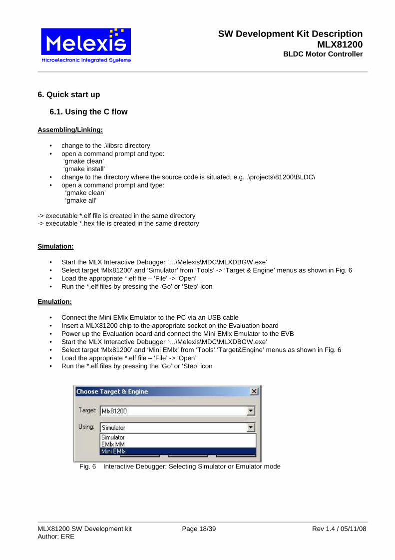
• Start the MLX Interactive Debugger ‘…\Melexis\MDC\MLXDBGW.exe’ • Select target ‘Mlx81200’ and ‘Simulator’ from ‘Tools’ -> ‘Target & Engine’ menus as shown in Fig. 6 • Load the appropriate *.elf file – ‘File’ -> ‘Open’ • Run the *.elf files by pressing the ‘Go’ or ‘Step’ icon
Emulation:
• Connect the Mini EMlx Emulator to the PC via an USB cable • Insert a MLX81200 chip to the appropriate socket on the Evaluation board • Power up the Evaluation board and connect the Mini EMlx Emulator to the EVB • Start the MLX Interactive Debugger ‘…\Melexis\MDC\MLXDBGW.exe’ • Select target ‘Mlx81200’ and ‘Mini EMlx’ from ‘Tools’ ‘Target&Engine’ menus as shown in Fig. 6 • Load the appropriate *.elf file – ‘File’ -> ‘Open’ • Run the *.elf files by pressing the ‘Go’ or ‘Step’ icon
Fig. 6 Interactive Debugger: Selecting Simulator or Emulator mode
SW Development Kit Description MLX81200
BLDC Motor Controller
MLX81200 SW Development kit Page 19/39 Rev 1.4 / 05/11/08 Author: ERE
Fig. 7 Melexis Interactive Debugger session
SW Development Kit Description MLX81200
BLDC Motor Controller
MLX81200 SW Development kit Page 20/39 Rev 1.4 / 05/11/08 Author: ERE
6.2. Programming a HEX file to the FLASH
• Connect the Mini E-MLX Emulator to the PC via an USB cable • Insert a MLX81200 chip into the socket and power up the EVB • Connect the Mini E-MLX Emulator (programmer) to the EVB • Start the programmer software ‘...\Programmer\EMlxMMProg.exe’ • Select File\Open… to open the Mlx81200 mmf file installed by Mlx81200Conf_x_x_x.msi
Fig. 8 E-Mlx MM Programmer: Path to the Mlx81200.mmf file
• Select ‘Tools\Options\Programming’ tick checkbox ‘Keep Supply between patterns’
Fig. 9 E-Mlx MM Programmer: Option “keep supply between pattern”
SW Development Kit Description MLX81200
BLDC Motor Controller
MLX81200 SW Development kit Page 21/39 Rev 1.4 / 05/11/08 Author: ERE
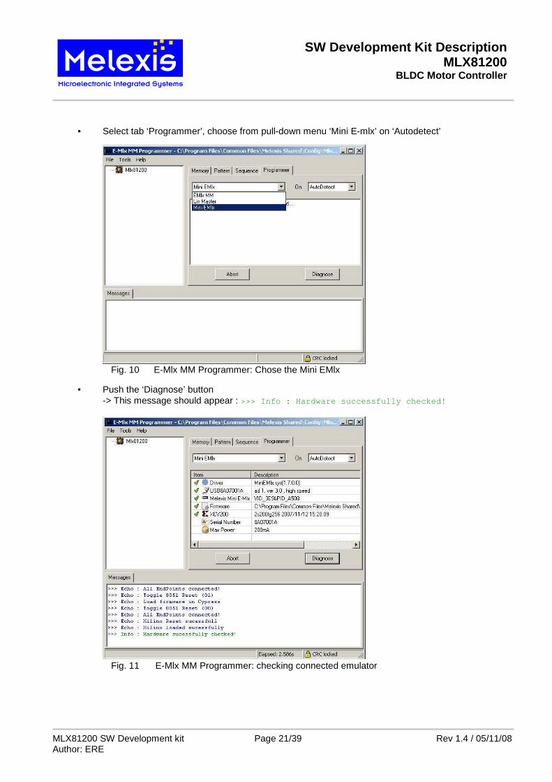
• Select tab ‘Programmer’, choose from pull-down menu ‘Mini E-mlx’ on ‘Autodetect’
Fig. 10 E-Mlx MM Programmer: Chose the Mini EMlx
• Push the ‘Diagnose’ button -> This message should appear : >>> Info : Hardware successfully checked!
Fig. 11 E-Mlx MM Programmer: checking connected emulator
SW Development Kit Description MLX81200
BLDC Motor Controller
MLX81200 SW Development kit Page 22/39 Rev 1.4 / 05/11/08 Author: ERE
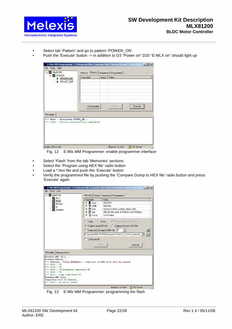
• Select tab ‘Pattern’ and go to pattern ‘POWER_ON’ • Push the ‘Execute’ button -> in addition to D3 “Power on” D20 “E-MLX on” should light up
Fig. 12 E-Mlx MM Programmer: enable programmer interface
• Select ‘Flash’ from the tab ‘Memories’ sections • Select the ‘Program using HEX file’ radio button • Load a *.hex file and push the ‘Execute’ button • Verify the programmed file by pushing the ‘Compare Dump to HEX file’ radio button and press ‘Execute’ again
Fig. 13 E-Mlx MM Programmer: programming the flash
SW Development Kit Description MLX81200
BLDC Motor Controller
MLX81200 SW Development kit Page 23/39 Rev 1.4 / 05/11/08 Author: ERE
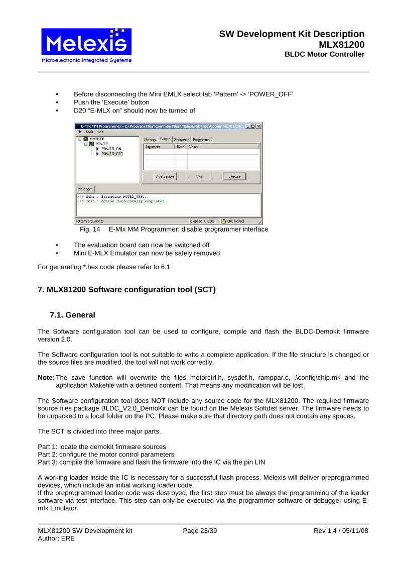
• Before disconnecting the Mini EMLX select tab ‘Pattern’ -> ‘POWER_OFF’ • Push the ‘Execute’ button • D20 “E-MLX on” should now be turned of
Fig. 14 E-Mlx MM Programmer: disable programmer interface
• The evaluation board can now be switched off • Mini E-MLX Emulator can now be safely removed
For generating *.hex code please refer to 6.1
7. MLX81200 Software configuration tool (SCT)
7.1. General The Software configuration tool can be used to configure, compile and flash the BLDC-Demokit firmware version 2.0. The Software configuration tool is not suitable to write a complete application. If the file structure is changed or the source files are modified, the tool will not work correctly. Note: The save function will overwrite the files motorctrl.h, sysdef.h, ramppar.c, .\config\chip.mk and the
application Makefile with a defined content. That means any modification will be lost. The Software configuration tool does NOT include any source code for the MLX81200. The required firmware source files package BLDC_V2.0_DemoKit can be found on the Melexis Softdist server. The firmware needs to be unpacked to a local folder on the PC. Please make sure that directory path does not contain any spaces. The SCT is divided into three major parts. Part 1: locate the demokit firmware sources Part 2: configure the motor control parameters Part 3: compile the firmware and flash the firmware into the IC via the pin LIN A working loader inside the IC is necessary for a successful flash process. Melexis will deliver preprogrammed devices, which include an initial working loader code. If the preprogrammed loader code was destroyed, the first step must be always the programming of the loader software via test interface. This step can only be executed via the programmer software or debugger using E-mlx Emulator.
SW Development Kit Description MLX81200
BLDC Motor Controller
MLX81200 SW Development kit Page 24/39 Rev 1.4 / 05/11/08 Author: ERE
For programming a HEX file to the flash via the test interface please refer to chapter 6.2 For further information please see: - the description for the MLX81200 BLDC Demo Kit firmware - Application Note how to program on module - Application Note how to flash over pin LIN
7.2. Locate the demokit firmware sources and load t he configuration
Fig. 15 MLX81200 SCT chose the path and load the configuration
1 Button “Browse” the path to BLDC firmware source 2 Project selector the current project name must be selected 3 Project name shows the current project name 4 Edit field “Target name” the name of the firmware 5 Button “read parameter” the configuration will be read from the chosen directory 6 Log Window each operation is shown in this window
1
2
5
6
3 4
SW Development Kit Description MLX81200
BLDC Motor Controller
MLX81200 SW Development kit Page 25/39 Rev 1.4 / 05/11/08 Author: ERE
7.3. Configure the demokit firmware
7.3.1. Test pulse configuration
Fig. 16 MLX81200 SCT – modify the parameter of the BLDC-demo kit
7 Parameter set “motor operation” 8 Parameter set “System setting” 9 Parameter set “Communication Interface settings” 10 Parameter set “Speed regulator settings” 11 Parameter set “Test pulse settings” 12 Parameter set “Motor start up test pulses”
7 8
11
9 10
12
SW Development Kit Description MLX81200
BLDC Motor Controller
MLX81200 SW Development kit Page 26/39 Rev 1.4 / 05/11/08 Author: ERE
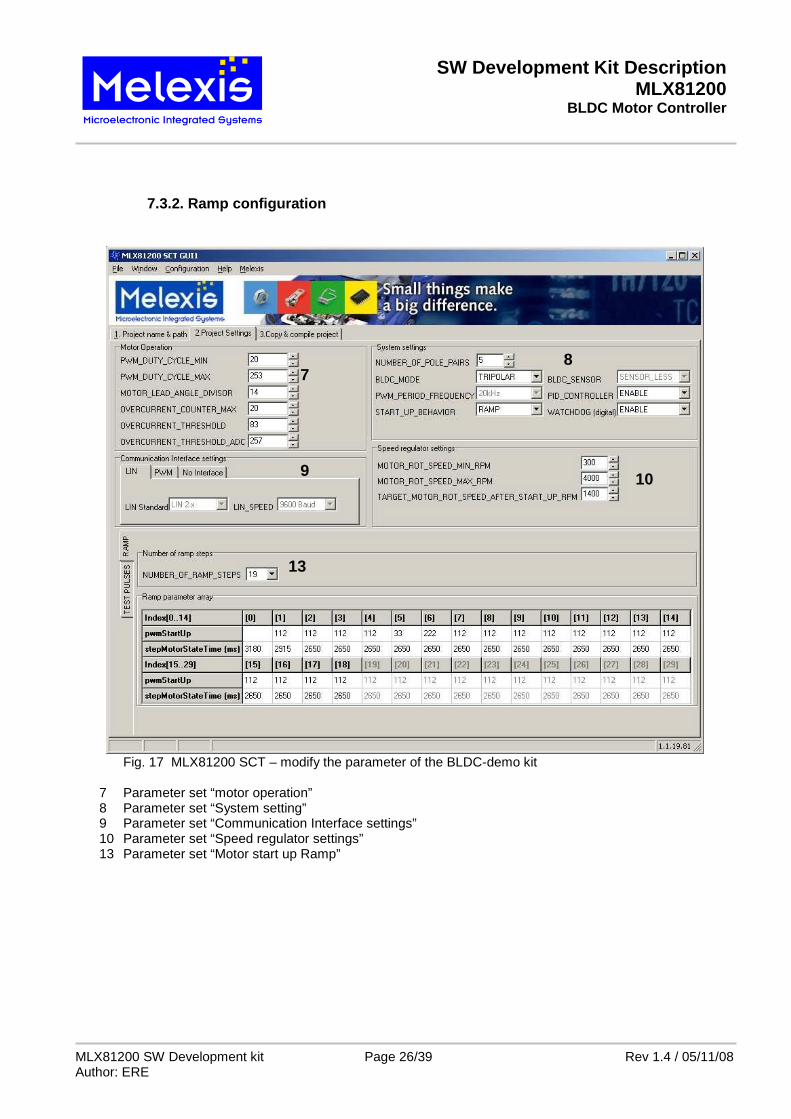
7.3.2. Ramp configuration
Fig. 17 MLX81200 SCT – modify the parameter of the BLDC-demo kit
7 Parameter set “motor operation” 8 Parameter set “System setting” 9 Parameter set “Communication Interface settings” 10 Parameter set “Speed regulator settings” 13 Parameter set “Motor start up Ramp”
7 8
9 10
13
SW Development Kit Description MLX81200
BLDC Motor Controller
MLX81200 SW Development kit Page 27/39 Rev 1.4 / 05/11/08 Author: ERE
7.4. Save, compile and program the firmware
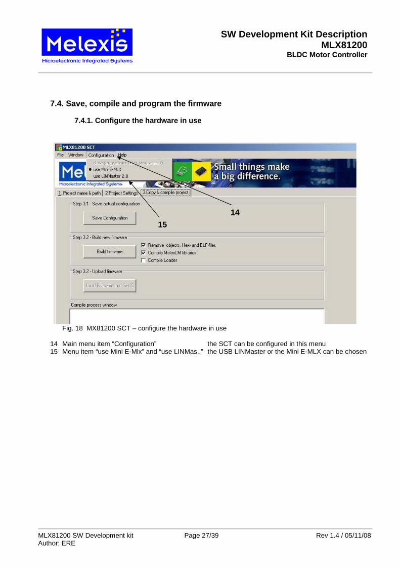
7.4.1. Configure the hardware in use
Fig. 18 MX81200 SCT – configure the hardware in use
14 Main menu item “Configuration” the SCT can be configured in this menu 15 Menu item “use Mini E-Mlx” and “use LINMas..” the USB LINMaster or the Mini E-MLX can be chosen
15
14
SW Development Kit Description MLX81200
BLDC Motor Controller
MLX81200 SW Development kit Page 28/39 Rev 1.4 / 05/11/08 Author: ERE
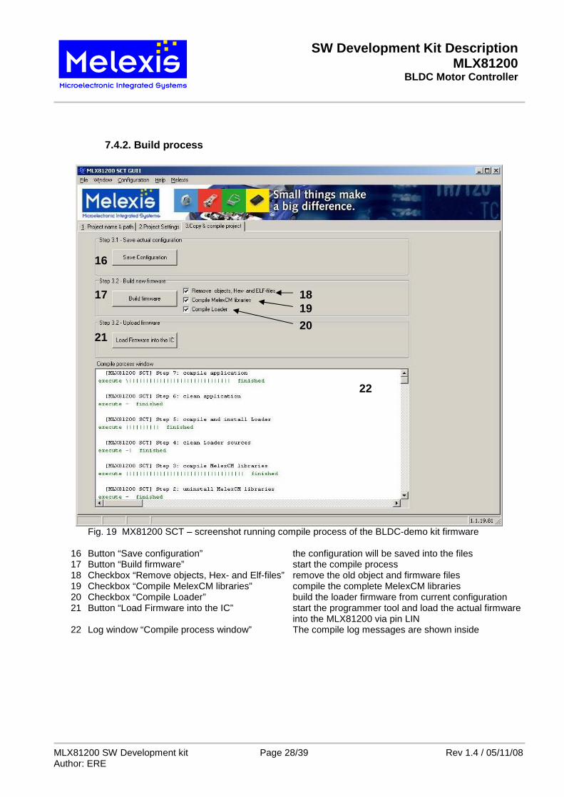
7.4.2. Build process
Fig. 19 MX81200 SCT – screenshot running compile process of the BLDC-demo kit firmware
16 Button “Save configuration” the configuration will be saved into the files 17 Button “Build firmware” start the compile process 18 Checkbox “Remove objects, Hex- and Elf-files” remove the old object and firmware files 19 Checkbox “Compile MelexCM libraries” compile the complete MelexCM libraries 20 Checkbox “Compile Loader” build the loader firmware from current configuration 21 Button “Load Firmware into the IC” start the programmer tool and load the actual firmware into the MLX81200 via pin LIN 22 Log window “Compile process window” The compile log messages are shown inside
17
16
18 19
20 21
22
SW Development Kit Description MLX81200
BLDC Motor Controller
MLX81200 SW Development kit Page 29/39 Rev 1.4 / 05/11/08 Author: ERE
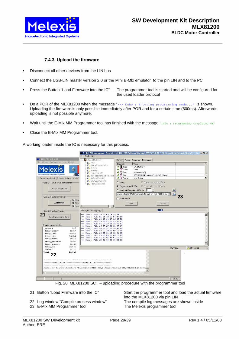
7.4.3. Upload the firmware • Disconnect all other devices from the LIN bus
• Connect the USB-LIN master version 2.0 or the Mini E-Mlx emulator to the pin LIN and to the PC
• Press the Button “Load Firmware into the IC” - The programmer tool is started and will be configured for the used loader protocol
• Do a POR of the MLX81200 when the message “>>> Echo : Entering programming mode...” is shown. Uploading the firmware is only possible immediately after POR and for a certain time (500ms). Afterwards uploading is not possible anymore.
• Wait until the E-Mlx MM Programmer tool has finished with the message “Info : Programming completed OK”
• Close the E-Mlx MM Programmer tool.
A working loader inside the IC is necessary for this process.
Fig. 20 MLX81200 SCT – uploading procedure with the programmer tool
21 Button “Load Firmware into the IC” Start the programmer tool and load the actual firmware into the MLX81200 via pin LIN 22 Log window “Compile process window” The compile log messages are shown inside 23 E-Mlx MM Programmer tool The Melexis programmer tool
21
23
22
SW Development Kit Description MLX81200
BLDC Motor Controller
MLX81200 SW Development kit Page 30/39 Rev 1.4 / 05/11/08 Author: ERE
8. BLDC DemoKit PC program
8.1. General The Motor control Software does NOT include any source code for the MLX81200. The required firmware file BLDC_V20_DemoKit_XY.hex MUST be loaded first into the MLX81200. The program MUST be running either by starting the program in the Melexis interactive debugger or let the CPU run free without the emulator out of power on reset. The BLDC Demokit Firmware can be controlled with the PC program via the LIN bus. The hysteresis brake board can be controlled via the LIN bus too. For programming a HEX file to the flash please refer to chapter 6.2
8.2. Command line parameter It is possible to configure the minimum and maximum speed slider values of the graphical interface. The default limits are 500 rpm for the minimum and 5000 rpm for the maximum. Following parameters are supported: • -maxspeed:x set the maximum limit • -minspeed:x set the minimum limit Example: The command: “MLX81200_Demokit_PC_program.exe –maxspeed:4000 –min speed:2000 ” starts the BLDC DemoKit PC program with a speed range from 2000 to 4000 rpm.
SW Development Kit Description MLX81200
BLDC Motor Controller
MLX81200 SW Development kit Page 31/39 Rev 1.4 / 05/11/08 Author: ERE
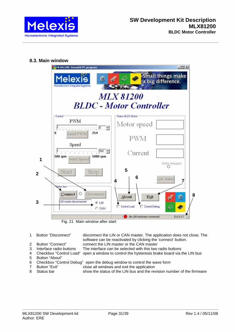
8.3. Main window
Fig. 21 Main window after start
1 Button “Disconnect” disconnect the LIN or CAN master. The application does not close. The software can be reactivated by clicking the ‘connect’ button.
2 Button “Connect” connect the LIN master or the CAN master 3 Interface radio buttons The interface can be selected with this two radio buttons 4 Checkbox “Control Load“ open a window to control the hysteresis brake board via the LIN bus 5 Button “About” 6 Checkbox “Control Debug” open the debug window to control the wave form 7 Button “Exit” close all windows and exit the application 8 Status bar show the status of the LIN bus and the revision number of the firmware
7
5
8
1
2 6
4
3
SW Development Kit Description MLX81200
BLDC Motor Controller
MLX81200 SW Development kit Page 32/39 Rev 1.4 / 05/11/08 Author: ERE
Fig. 22 Main window with connected LIN master
9 Control bar “PWM” adjust the PWM value (send to MLX81200 with button 10) 10 Button ”Send PWM” send the adjusted PWM value to the MLX81200 11 Control bar “Speed” adjust motor speed (send to MLX81200 with button 12) 12 Button “Send Speed” send the adjusted speed value to the MLX81200 13 Button “Start” start the motor Note: The default speed target after start command is 1200U/min 14 Button “Stop” stop the motor immediately 15 Status window shows the current motor speed , PWM value , motor status and the current
Note: If the CAN interface is used, the value of the current will not be transferred
16 Button “Get Status” Click this button to get the actual status of the motor ( shown in 15 ) Note: the received values of the PWM and speed will be transferred automatically to the control bars (9 and 11)
17 Checkbox “continuously” get the motor status and send the target speed value every 150 ms.
9
11
10
12
13
14
15
16
17
SW Development Kit Description MLX81200
BLDC Motor Controller
MLX81200 SW Development kit Page 33/39 Rev 1.4 / 05/11/08 Author: ERE
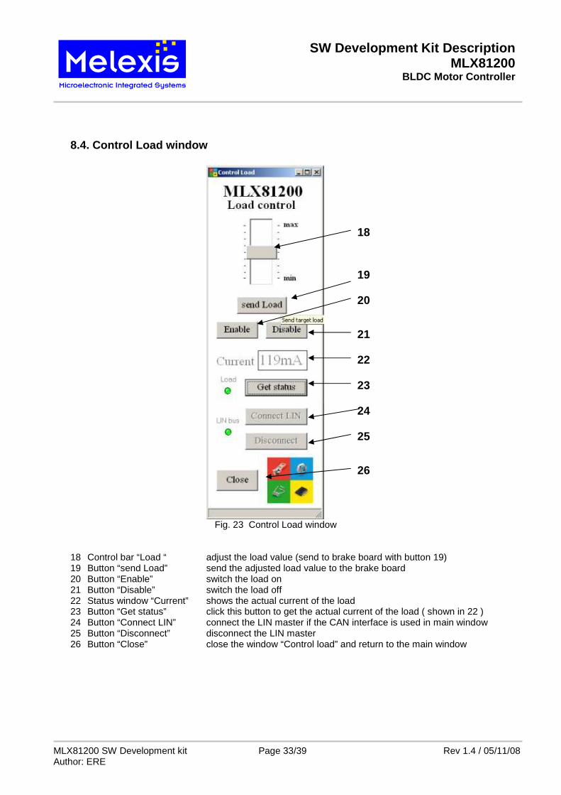
8.4. Control Load window
Fig. 23 Control Load window
18 Control bar “Load “ adjust the load value (send to brake board with button 19) 19 Button “send Load” send the adjusted load value to the brake board 20 Button “Enable” switch the load on 21 Button “Disable” switch the load off 22 Status window “Current” shows the actual current of the load 23 Button “Get status” click this button to get the actual current of the load ( shown in 22 ) 24 Button “Connect LIN” connect the LIN master if the CAN interface is used in main window 25 Button “Disconnect” disconnect the LIN master 26 Button “Close” close the window “Control load” and return to the main window
18
19
20
21
22
23
24
25
26
SW Development Kit Description MLX81200
BLDC Motor Controller
MLX81200 SW Development kit Page 34/39 Rev 1.4 / 05/11/08 Author: ERE
8.5. Control Debug window
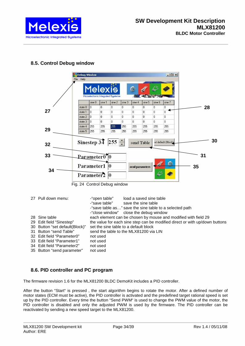
Fig. 24 Control Debug window
27 Pull down menu: -“open table” load a saved sine table -“save table” save the sine table -“save table as…” save the sine table to a selected path -“close window” close the debug window 28 Sine table each element can be chosen by mouse and modified with field 29 29 Edit field “Sinestep” the value for each sine step can be modified direct or with up/down buttons 30 Button “set default(Block)” set the sine table to a default block 31 Button “send Table” send the table to the MLX81200 via LIN 32 Edit field “Parameter0” not used 33 Edit field “Parameter1” not used 34 Edit field “Parameter2” not used 35 Button “send parameter” not used
8.6. PID controller and PC program The firmware revision 1.6 for the MLX81200 BLDC DemoKit includes a PID controller. After the button “Start“ is pressed , the start algorithm begins to rotate the motor. After a defined number of motor states (ECM must be active), the PID controller is activated and the predefined target rational speed is set up by the PID controller. Every time the button “Send PWM“ is used to change the PWM value of the motor, the PID controller is disabled and only the adjusted PWM is used by the firmware. The PID controller can be reactivated by sending a new speed target to the MLX81200.
28
29
27
30
31
35
32
33
34
SW Development Kit Description MLX81200
BLDC Motor Controller
MLX81200 SW Development kit Page 35/39 Rev 1.4 / 05/11/08 Author: ERE
9. Appendix
9.1. Schematics of the Evaluation Board
Fig. 25 Schematics of the Evaluation board
SW Development Kit Description MLX81200
BLDC Motor Controller
MLX81200 SW Development kit Page 36/39 Rev 1.4 / 05/11/08 Author: ERE
9.2. Schematic of the Evaluation Board – Part 2 Pro grammer Interface
Fig. 26 Schematics of the Programmer board
SW Development Kit Description MLX81200
BLDC Motor Controller
MLX81200 SW Development kit Page 37/39 Rev 1.4 / 05/11/08 Author: ERE
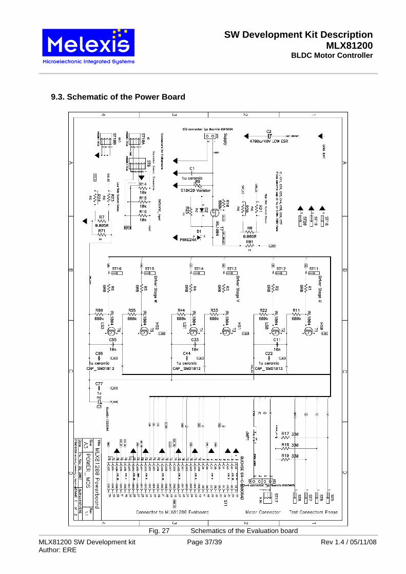
9.3. Schematic of the Power Board
Fig. 27 Schematics of the Evaluation board
SW Development Kit Description MLX81200
BLDC Motor Controller
MLX81200 SW Development kit Page 38/39 Rev 1.4 / 05/11/08 Author: ERE
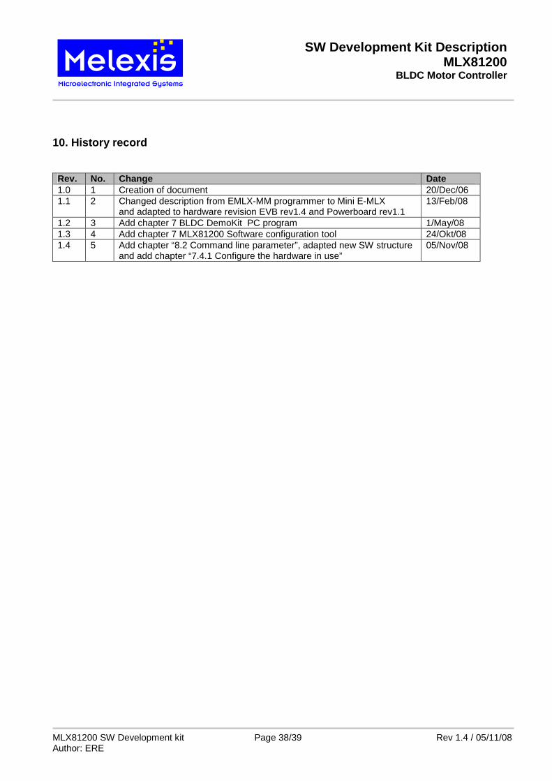
10. History record Rev. No. Change Date 1.0 1 Creation of document 20/Dec/06 1.1 2 Changed description from EMLX-MM programmer to Mini E-MLX
and adapted to hardware revision EVB rev1.4 and Powerboard rev1.1 13/Feb/08
1.2 3 Add chapter 7 BLDC DemoKit PC program 1/May/08 1.3 4 Add chapter 7 MLX81200 Software configuration tool 24/Okt/08 1.4 5 Add chapter “8.2 Command line parameter”, adapted new SW structure
and add chapter “7.4.1 Configure the hardware in use” 05/Nov/08
SW Development Kit Description MLX81200
BLDC Motor Controller
MLX81200 SW Development kit Page 39/39 Rev 1.4 / 05/11/08 Author: ERE