CTLS LSA SERIAL NUMBER:_______________ Maintenance and Inspection Procedures Manual THIS DOCUMENT AND THE TECHNICAL DATA HEREON DISCLOSED ARE PROPRIETARY TO FLIGHT DESIGN AND SHALL NOT BE USED, RELEASED, OR DISCLOSED IN WHOLE OR IN PART WITHOUT EXPRESS WRITTEN PERMISSION FROM FLIGHT DESIGN
Transcript
CTLS LSA
SERIAL NUMBER:_______________
Maintenance and Inspection Procedures Manual
THIS DOCUMENT AND THE TECHNICAL DATA HEREON DISCLOSED ARE PROPRIETARY TO FLIGHT DESIGN AND SHALL NOT BE USED, RELEASED, OR DISCLOSED IN WHOLE OR IN PART WITHOUT EXPRESS WRITTEN PERMISSION FROM
FLIGHT DESIGN
Maintenance and Inspection Procedures Manual Type: CT Series: CTLS LSA Page: ii
AF 04800001 Revision No. 4 Date: 02 Jan 2009
REVISION STATUS
Rev Pages Date Chapter completed
1 All Jan 10, 2008 All Vasyl Sys - System of pages numbering changed - Formatting (page breaks) partially changed All “or higher grade of certificate” added to
“Repairman, Light Sport Aircraft-Maintenance (RLSA-M).”
3-1 – 10-5 Allocation of Level of Maintenance and Level of Certification detailed and adapted. Requirements for Flight Design Training reviewed. Linguistic clarifying corrections included throughout the whole procedures.
O. Reinhardt
1-1 Address of Flight Design is changed 4 AІV-1-AІV-14
02 Jan 2009 Added Appendix IV MATCO Brake System
S. Pilipenko
Maintenance and Inspection Procedures Manual Type: CT Series: CTLS LSA Page: iii
AF 04800001 Revision No. 4 Date: 02 Jan 2009
LIST OF EFFECTIVE PAGES CHAPTER CHAPTER CHAPTER CHAPTER
Maintenance and Inspection Procedures Manual Type: CT Series: CTLS LSA Page: iv
AF 04800001 Revision No. 3 Date: 14 Sep 2008
TABLE OF CONTENTS 1 General ............................................................................................................................................ 1-1
1.1 Manufacturer ............................................................................................................................. 1-1 1.2 Contact in USA.......................................................................................................................... 1-1 1.3 Care and cleaning of your CT ................................................................................................... 1-2 1.4 Views, dimensions .................................................................................................................... 1-3 1.5 Construction Materials .............................................................................................................. 1-5 1.6 Equipment List .......................................................................................................................... 1-6 1.7 Source to Purchase Parts ......................................................................................................... 1-7 1.8 List of Disposable Replacement Parts ...................................................................................... 1-7 1.9 Weight and Balance Information............................................................................................... 1-8 1.10 Tire Inflation Pressure............................................................................................................. 1-10 1.11 Approved Fluids and Capacities ............................................................................................. 1-10 1.12 Recommended Fastener Torque Values and Bolts Installation ............................................. 1-11 1.13 General Safety Information ..................................................................................................... 1-12 1.14 Instructions for Reporting Possible Safety of Flight Concerns Found During Inspection /
Maintenance............................................................................................................................ 1-13 2 Minimum Levels of Certification:...................................................................................................... 2-1
2.1 General ..................................................................................................................................... 2-1 2.2 Levels of certification................................................................................................................. 2-1 2.3 Required certification level for maintenance procedures.......................................................... 2-2
4.2.1.4.1 Type of Maintenance ........................................................................................... 4-11 4.2.1.4.2 Minimum Level of Certification ............................................................................ 4-11 4.2.1.4.3 Visual Inspection ................................................................................................. 4-11 4.2.1.4.4 Shock Absorber Inspection.................................................................................. 4-12 4.2.1.4.5 Fork Inspection .................................................................................................... 4-12 4.2.1.4.6 Nose Wheel Inspection........................................................................................ 4-12
4.2.1.5 Nose Gear Removal (Replacement)......................................................................... 4-13 4.2.1.5.1 Type of Maintenance ........................................................................................... 4-13
Maintenance and Inspection Procedures Manual Type: CT Series: CTLS LSA Page: v
4.2.1.6 Nose Wheel............................................................................................................... 4-16 4.2.1.6.1 Type of Maintenance ........................................................................................... 4-16 4.2.1.6.2 Minimum Level of Certification ............................................................................ 4-16 4.2.1.6.3 Nose Wheel Removal and Installation ................................................................ 4-16
4.2.2.4.1 Type of Maintenance ........................................................................................... 4-19 4.2.2.4.2 Minimum Level of Certification ............................................................................ 4-19 4.2.2.4.3 Visual inspection.................................................................................................. 4-19 4.2.2.4.4 Wheel Inspection ................................................................................................. 4-19
4.2.2.5 Main Wheel Fairing Removal (Replacement) ........................................................... 4-19 4.2.2.5.1 Type of Maintenance ........................................................................................... 4-19 4.2.2.5.2 Minimum Level of Certification ............................................................................ 4-19 4.2.2.5.3 Procedure ............................................................................................................ 4-20
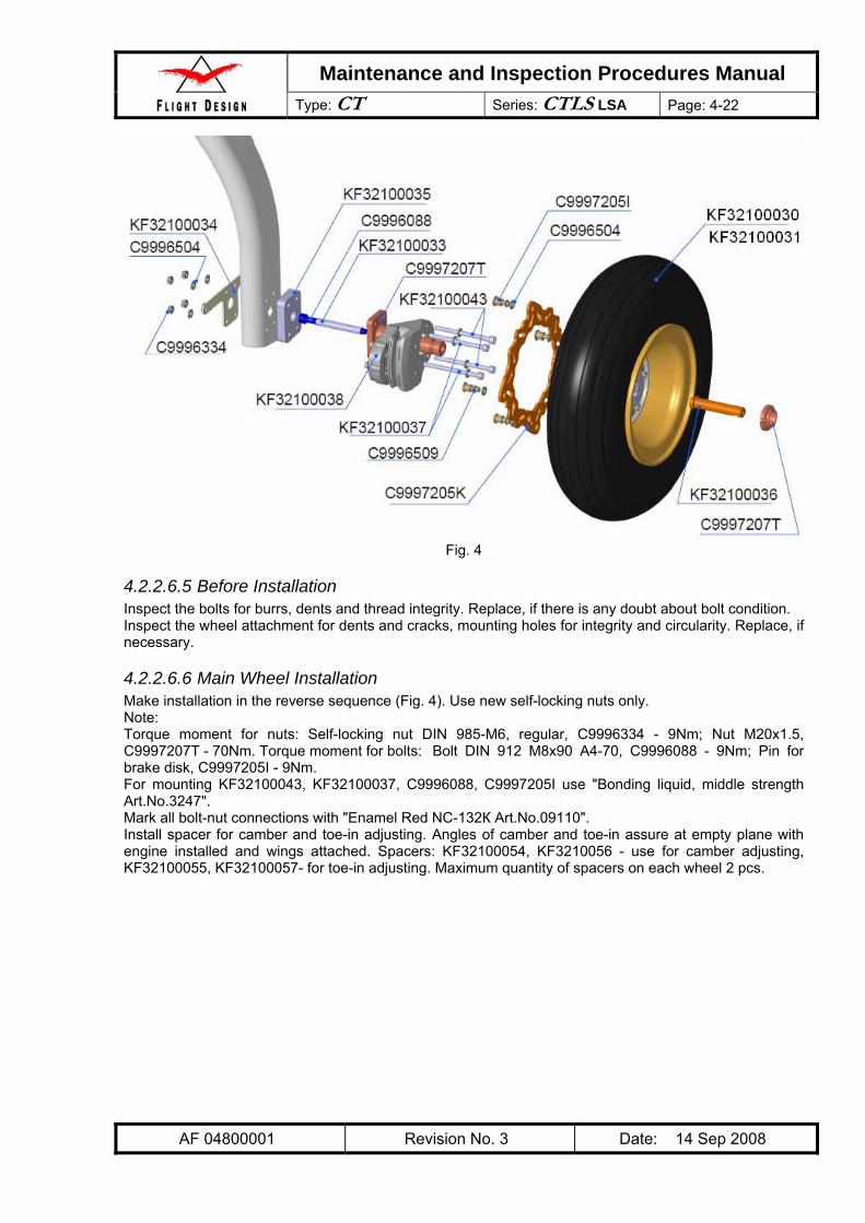
4.2.2.6 Main Wheel Removal and Installation ...................................................................... 4-21 4.2.2.6.1 Type of Maintenance ........................................................................................... 4-21 4.2.2.6.2 Minimum Level of Certification ............................................................................ 4-21 4.2.2.6.3 Wheel Brake Line Disconnecting ........................................................................ 4-21 4.2.2.6.4 Main Wheel Removal .......................................................................................... 4-21 4.2.2.6.5 Before Installation................................................................................................ 4-22 4.2.2.6.6 Main Wheel Installation ....................................................................................... 4-22
4.2.2.7 Removal (Replacement) of Main Strut Fairing.......................................................... 4-23 4.2.2.7.1 Type of Maintenance ........................................................................................... 4-23 4.2.2.7.2 Minimum Level of Certification ............................................................................ 4-23
4.2.2.8 Main Gear Struts Removal and Installation .............................................................. 4-24 4.2.2.8.1 Type of Maintenance ........................................................................................... 4-24 4.2.2.8.2 Minimum Level of Certification ............................................................................ 4-24 4.2.2.8.3 Procedure ............................................................................................................ 4-24
4.2.2.9 Wheel Inspection and Maintenance.......................................................................... 4-25 4.2.2.9.1 Type of Maintenance ........................................................................................... 4-25 4.2.2.9.2 Minimum Level of Certification ............................................................................ 4-25 4.2.2.9.3 Procedure ............................................................................................................ 4-25
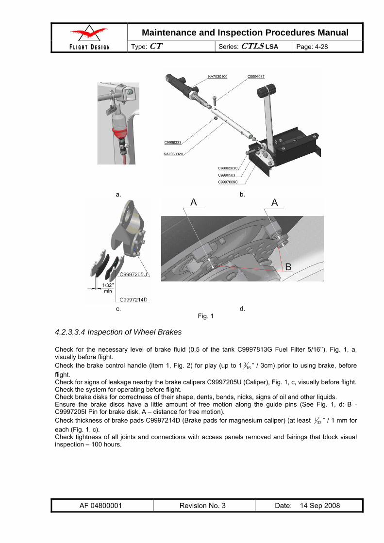
4.2.3.3.1 Type of Maintenance ........................................................................................... 4-27 4.2.3.3.2 Minimum Level of Certification ............................................................................ 4-27 4.2.3.3.3 General ................................................................................................................ 4-27 4.2.3.3.4 Inspection of Wheel Brakes................................................................................. 4-28 4.2.3.3.5 Inspection of Brake Controls ............................................................................... 4-29
4.2.3.4 Filling Brake System with Fluid................................................................................. 4-31 4.2.3.4.1 Type of Maintenance ........................................................................................... 4-31 4.2.3.4.2 Minimum Level of Certification ............................................................................ 4-31 4.2.3.4.3 Procedure ............................................................................................................ 4-31
4.2.3.5 Brake Pads Replacement ......................................................................................... 4-32 4.2.3.5.1 Type of Maintenance ........................................................................................... 4-32 4.2.3.5.2 Minimum Level of Certification ............................................................................ 4-32 4.2.3.5.3 Procedure ............................................................................................................ 4-32
4.3.2.5 Flap Installation......................................................................................................... 4-51 4.3.2.5.1 Type of Maintenance ........................................................................................... 4-51 4.3.2.5.2 Minimum Level of Certification ............................................................................ 4-51 4.3.2.5.3 Procedure ............................................................................................................ 4-51
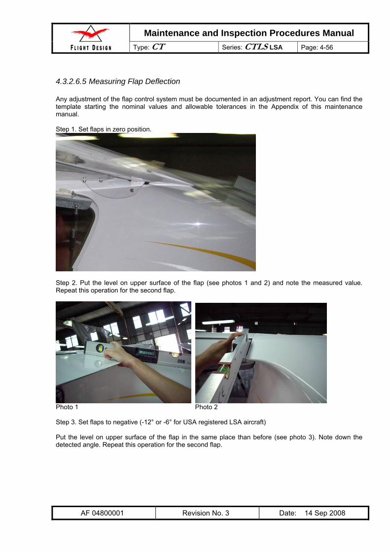
4.3.2.6 Flap Adjustment ........................................................................................................ 4-53 4.3.2.6.1 Type of Maintenance ........................................................................................... 4-53 4.3.2.6.2 Minimum Level of Certification ............................................................................ 4-53 4.3.2.6.3 Rigging “Zero” Position of the Flaps.................................................................... 4-53 4.3.2.6.4 Flap Deflection Adjustment.................................................................................. 4-54 4.3.2.6.5 Measuring Flap Deflection................................................................................... 4-56
4.3.2.7 Inspection of Flap Control Microswitches ................................................................. 4-59 4.3.2.7.1 Type of Maintenance ........................................................................................... 4-59 4.3.2.7.2 Minimum Level of Certification ............................................................................ 4-59 4.3.2.7.3 Procedure ............................................................................................................ 4-59
4.3.3.3.1 Type of Maintenance ........................................................................................... 4-60 4.3.3.3.2 Minimum Level of Certification Required............................................................. 4-60 4.3.3.3.3 Procedure ............................................................................................................ 4-60
4.3.3.4 Rudder Deflection Adjustment .................................................................................. 4-63 4.3.3.4.1 Type of Maintenance ........................................................................................... 4-63 4.3.3.4.2 Minimum Level of Certification ............................................................................ 4-63 4.3.3.4.3 Measuring Rudder Deflection.............................................................................. 4-64 4.3.3.4.4 Rigging Rudder Neutral Position ......................................................................... 4-66 4.3.3.4.5 Adjusting of Control Cable Tension..................................................................... 4-67 4.3.3.4.6 Fine Adjustment................................................................................................... 4-68
Maintenance and Inspection Procedures Manual Type: CT Series: CTLS LSA Page: vii
AF 04800001 Revision No. 3 Date: 14 Sep 2008
4.3.3.4.7 Coarse Adjustment .............................................................................................. 4-68 4.3.3.5 Verification of Rudder Installation and Adjustment................................................... 4-69
4.3.4 Stabilator............................................................................................................................ 4-70 4.3.4.1 Tools Required.......................................................................................................... 4-71 4.3.4.2 Parts and Materials Required ................................................................................... 4-71 4.3.4.3 General ..................................................................................................................... 4-71 4.3.4.4 Stabilator Installation and Removal .......................................................................... 4-71
4.3.4.4.1 Type of Maintenance ........................................................................................... 4-71 4.3.4.4.2 Minimum Level of Certification ............................................................................ 4-71 4.3.4.4.3 Procedure ............................................................................................................ 4-71
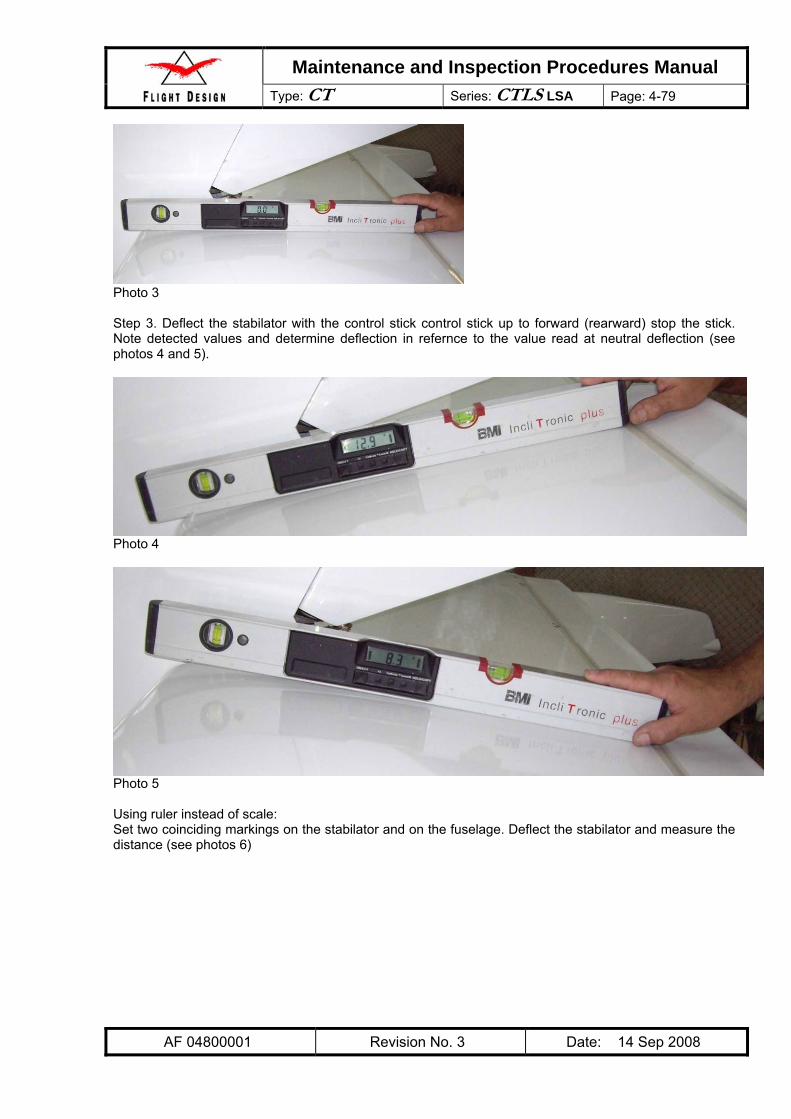
4.3.4.5 Stabilator Adjustment................................................................................................ 4-77 4.3.4.5.1 Type of Maintenance ........................................................................................... 4-77 4.3.4.5.2 Minimum Level of Certification ............................................................................ 4-77 4.3.4.5.3 Measuring Stabilator Deflection........................................................................... 4-78 4.3.4.5.4 Measuring of Trim Tab Deflection and Adjustment ............................................. 4-81
4.3.4.6 Balancing of the Stabilator Balancer......................................................................... 4-83 4.3.4.6.1 Type of Maintenance ........................................................................................... 4-83 4.3.4.6.2 Minimum Level of Certification ............................................................................ 4-83 4.3.4.6.3 Procedure ............................................................................................................ 4-83
4.3.4.7 Verification of Stabilator Installation and Adjustment ............................................... 4-84 4.4 Structural Repair ..................................................................................................................... 4-85
4.4.1 Type of Maintenance ......................................................................................................... 4-85 4.4.2 Minimum Level of Certification .......................................................................................... 4-85 4.4.3 Repair Procedures............................................................................................................. 4-85
4.5 Painting and Coating............................................................................................................... 4-85 4.5.1 Tools needed to accomplish the task ................................................................................ 4-85 4.5.2 The parts needed to perform the task ............................................................................... 4-85 4.5.3 Type of Maintenance ......................................................................................................... 4-85 4.5.4 Minimum Level of Certification .......................................................................................... 4-85 4.5.5 Puttying.............................................................................................................................. 4-85 4.5.6 Priming............................................................................................................................... 4-86 4.5.7 Painting.............................................................................................................................. 4-86 4.5.8 Polishing ............................................................................................................................ 4-86 4.5.9 Method of Verification........................................................................................................ 4-86
5 Engine.............................................................................................................................................. 5-1 5.1 Engine Systems and Accessories............................................................................................. 5-1 5.2 Rotax 912ULS Engine............................................................................................................... 5-1 5.3 Carb Heat Control ..................................................................................................................... 5-2
5.3.1 Tools Required .................................................................................................................... 5-2 5.3.2 Materials Required............................................................................................................... 5-2 5.3.3 Type of Maintenance ........................................................................................................... 5-2 5.3.4 Minimum Level of Certification ............................................................................................ 5-2 5.3.5 General ................................................................................................................................ 5-2 5.3.6 Inspection of Carburetor Heater Control.............................................................................. 5-2
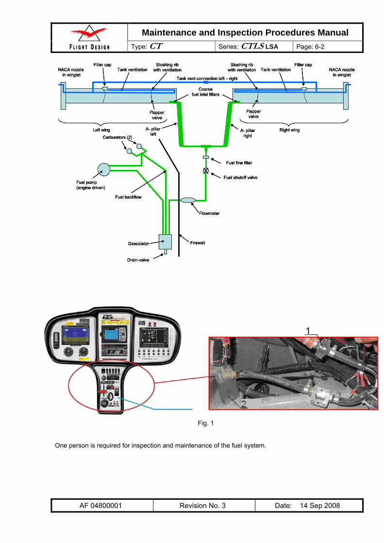
6 Fuel System..................................................................................................................................... 6-1 6.1 General ..................................................................................................................................... 6-1 6.2 Tools Required.......................................................................................................................... 6-3 6.3 Materials Required .................................................................................................................... 6-3 6.4 General System Inspection....................................................................................................... 6-3
6.4.1 Type of Maintenance ........................................................................................................... 6-3 6.4.2 Minimum Level of Certification ............................................................................................ 6-3 6.4.3 Procedure ............................................................................................................................ 6-3
6.5 Fuel Flow Check ....................................................................................................................... 6-4 6.5.1 Type of Maintenance ........................................................................................................... 6-4 6.5.2 Minimum Level of Certification ............................................................................................ 6-4 6.5.3 Checking of Fuel Flow Rate ................................................................................................ 6-4 6.5.4 Simulation of In-Flight Engine Restart ................................................................................. 6-4
6.6 Intake Filter / Side Access Panel .............................................................................................. 6-6 6.6.1 Type of Maintenance ........................................................................................................... 6-6
Maintenance and Inspection Procedures Manual Type: CT Series: CTLS LSA Page: viii
6.7 Fuel Filter .................................................................................................................................. 6-8 6.7.1 Type of Maintenance ........................................................................................................... 6-8 6.7.2 Minimum Level of Certification ............................................................................................ 6-8 6.7.3 Procedure ............................................................................................................................ 6-8
6.8 Gascolator................................................................................................................................. 6-9 6.8.1 Type of Maintenance ........................................................................................................... 6-9 6.8.2 Minimum Level of Certification ............................................................................................ 6-9 6.8.3 Procedure ............................................................................................................................ 6-9
7 Propeller .......................................................................................................................................... 7-1 7.1 Type of Maintenance................................................................................................................. 7-1 7.2 Minimum Level of Certification.................................................................................................. 7-1 7.3 Propeller Maintenance Procedures........................................................................................... 7-1
8 Utility Systems ................................................................................................................................. 8-1 8.1 Tools Required.......................................................................................................................... 8-1 8.2 Materials Required .................................................................................................................... 8-1 8.3 Cabin Heat System ................................................................................................................... 8-1
8.3.1.1 Type of Maintenance .................................................................................................. 8-1 8.3.1.2 Minimum Level of Certification.................................................................................... 8-1 8.3.1.3 Procedure.................................................................................................................... 8-1
9 Instruments and Avionics ................................................................................................................ 9-1 9.1 Tools Required.......................................................................................................................... 9-1 9.2 Parts Required .......................................................................................................................... 9-1 9.3 Instrument Maintenance............................................................................................................ 9-1
9.3.1 Type of Maintenance ........................................................................................................... 9-1 9.3.2 Minimum Level of Certification ............................................................................................ 9-1 9.3.3 General ................................................................................................................................ 9-1 9.3.4 Glass Cockpit Dynon EFIS 100 ........................................................................................... 9-1 9.3.5 Glass Cockpit Dynon EMS D120......................................................................................... 9-1 9.3.6 Analog Airspeed Indicator ................................................................................................... 9-2 9.3.7 Analog One Pointer Altimeter .............................................................................................. 9-2 9.3.8 Magnetic Compass with Deviation Table ............................................................................ 9-2 9.3.9 Flap position indicator.......................................................................................................... 9-2 9.3.10 Hobbs Hour Meter ........................................................................................................... 9-2 9.3.11 Radio Garmin SL30 with VOR functionality .................................................................... 9-2 9.3.12 Radio Garmin SL40 installed with antenna..................................................................... 9-2 9.3.13 Transponder Garmin installation ..................................................................................... 9-3 9.3.14 Altitude Encoder ACK A30 (Classic) or Dynon (Advanced)............................................ 9-3 9.3.15 GPS Garmin 496 ............................................................................................................. 9-3 9.3.16 ELT Ameriking AK450..................................................................................................... 9-3 9.3.17 Intercom PM 3000 A with aux music input and connection to GPS Audio ..................... 9-3
9.4 Inspection of Pitot & Static Port ................................................................................................ 9-4 9.4.1 Type of Maintenance ........................................................................................................... 9-4 9.4.2 Minimum Level of Certification ............................................................................................ 9-4 9.4.3 Procedure ............................................................................................................................ 9-4
9.5 Special Equipment .................................................................................................................... 9-5 10 Electrical System ........................................................................................................................... 10-1
10.3.1 Inspection ...................................................................................................................... 10-5 10.3.1.1 Type of Maintenance ............................................................................................ 10-5 10.3.1.2 Minimum Level of Certification ............................................................................. 10-5 10.3.1.3 Procedure ............................................................................................................. 10-5
10.4 Battery Replacement............................................................................................................... 10-5 10.4.1 Type of Maintenance..................................................................................................... 10-5 10.4.2 Minimum Level of Certification ...................................................................................... 10-5 10.4.3 Procedure...................................................................................................................... 10-5
Maintenance and Inspection Procedures Manual Type: CT Series: CTLS LSA Page: ix
AF 04800001 Revision No. 4 Date: 02 Jan 2009
Appendix I . Template for Trim Tab Deflection Angles Measurement ..........................................................1 Appendix II. Adjustment report ......................................................................................................................1 Appendix III . Service Difficulty Report Form ................................................................................................1 Appendix IV . MATCO Brake System...........................................................................................................1
1 General This maintenance and inspection procedures manual provides all standard maintenance and inspection procedures needed to keep the aircraft airworthy. This manual also states the certification requirements for the persons performing each task. Maintenance tasks exceeding the scope of this manual are possible but require prior coordination with and approval by the manufacturer. The Flight Design CTLS is a three-axis control, high-wing, and two seats light sport aircraft of normal scheme with a cruciform tail. The primary structures are made of carbon fiber reinforced plastic. The aircraft is equipped with an all-moving stabilator with a trim tab and tricycle landing gear with a steerable nose-wheel. Federal rules require minimum certification levels of the mechanics perfoming individual maintenance tasks on an S-LSA aircraft to be defined by the airframe manufacturer. Refer to chapter 2 for the definition of the levels of certification applied throutghout this manual. On each individual task you will find the allocation of level of certification. WARNING: Use only alkali-free products when cleaning your composite aircraft. For
more information, refer to chapter 1.3 Care and cleaning of your CT.
1.1 Manufacturer Flight Design GmbH Sielminger Str. 51 D – 70771 L.-Echterdingen Germany
1.2 Contact in USA Flight Design USA P.O. Box 325 South Woodstock, CT. 06267 860-963-7272 [email protected]
Care must be taken when cleaning modern aircraft built with composite materials. Many products have been developed to clean a specific type of material and may be unsuitable or even damaging to others. Using the wrong product may damage your aircraft or its structures. Affected parts may be plainly visible or may be hidden from view. The type of damage can vary from the simply unsightly to the outright dangerous. You must always read the instructions for your cleaning products before using them. If you should have any questions about a product’s suitability please contact your local dealer. Each structure has its own cleaning requirements. The basic airframe and wing structure Composite aircraft are typically constructed of a sandwich of a structural material (Fiberglass-Carbon Fiber or Kevlar) over a foam core. The Flight Design CTLS is made up of a Carbon fiber-foam-Carbon fiber and Kevlar laminate sandwich which is filled with polyester filler, sanded and painted with two-part urethane paint. The foam core of the wings is partially Rohacell foam which was chosen for its stiffness and resistance to fuel. The fuselage core is Airex foam which allows the contours for the CTLS fuselage. The Rohacell foam, while highly resistant to fuel, is not resistant to strong Alkali cleaners or even water with very high alkali content. Therefore Flight Design requires that the cleaners used on the CTLS be PH neutral. Cleaners, such as Fantastik®, Formula 409®, Carbonex® and Castrol Super Clean®, which are otherwise good Alkali cleaning products, should not be used on the CTLS. The use of this category cleaner can dissolve the foam core of the sandwich leaving a dented looking area that must be repaired and re-painted. Please note that the wing spars of the CTLS are sealed in epoxy and fiberglass and cannot be damaged in this manner. The windshield and side windows The windows of the CTLS are tinted, heat molded acrylic (also known as Plexiglas®). While durable, they must be carefully cleaned to avoid scratching the surface. Never use an abrasive pad, abrasive pastes or even dirty rags when cleaning the window surfaces. Always flush the window surface with water to remove as much dust and dirt before using an aircraft window specific cleaner or a plastic cleaner approved for cleaning acrylic windshields. When polishing the windshield or side windows never polish in a circular motion, this creates a halo affect when looking into the sun. Always use horizontal or vertical pattern. The engine and engine compartment The Rotax 912 maintenance manual recommends the use of a commercially available cold cleaning agent. Some citrus based products have been found to be suitable. However, always read the instructions for any product to be used, keeping in mind that it must be compatible with both the engine components and the airframe structures.
1.5 Construction Materials The airframe is made of high-quality composite materials which permit excellent aerodynamic characteristics to be achieved at an efficient structural mass. Due to the strict mass regulations for ultra-light aircraft, re-inforced carbon and aramide fiber materials predominate. Due to the complex nature of composite materials and the necessary knowledge in the lay-up of a specific structure, repair work on the composite airframe may only be undertaken by a qualified facility. For this reason, only general information about the materials used is given in this handbook. Should the aircraft structure be damaged, detailed information should be requested from the manufacturer.
Carbon, aramide, glass fiber: various qualities Lange & Ritter, Gerlingen
Resin and hardener: Larit L 285 Lange & Ritter, Gerlingen
Core material: Rohacell, Airex various qualities Lange & Ritter, Gerlingen
Screws and bolts: unless otherwise stated, class 8.8 zinc-plated or stainless steel, according to DIN standard
1.6 Equipment List Each aircraft is delivered with an initial equipment list as part of this handbook. A new equipment list must be compiled and added to aircraft logbook and to this manual when there is any change to the equipment. The owner of the aircraft is responsible for ensuring that the equipment list is current. The equipment list includes options which are not certified in all the countries in which the CTLS may be operated. It is the responsibility of the owner to ensure that national regulations are followed, for example with respect to the ballistic recovery system and the autopilot. The equipment list is a summary of the aircraft at the time of an annual inspection or weighing. It is mandatory to record the installation and/or removal of instruments in the aircraft logbook.
. Note: Sample weight and balance sheet only; not valid for the actual aircraft.
1.7 Source to Purchase Parts Spare parts can be ordered from Flight Design USA (www.flightdesignusa.com ) along the Parts and Assemblies Manual.
1.8 List of Disposable Replacement Parts Air filter Air filter C2039, Art. C9997770 Fuel filter Fuel Filter 5/16’’, Art C9997813G Oil filter Oil filter – according to Rotax maintenance manual
Front & Main wheel
Tyre 4.00-6 BfGoodrich 4PR PowerHoby Tyre 4-ply 4.00 - 6" /4 PR V-5501 TT (B11) Tyre 6PR Sava 4.00-6 6PR B11 Tube 3.50-6" not certified Tube 4.00-6 Pn TR13 Tube Sava, 3.5.00-6 38G11.5, 6 ply
Tundra front wheel
Tube 4.00-6 Pn TR13 or Tire 4.00-6 BfGoodrich 4PR PowerHoby
Tundra main wheel
Tyre 4-ply 6,00-6" Air TRAC (420x140) or Tyre 4-ply 6,00-6" Air TRAC
Batteries
Battery Powersafe SBS 8 or Battery Cyclon Master brake cylinder, Art C9997205L O-Ring set for master brake cylinder Brake pads for magnesium caliper, Art C9997214D Aeroshell fluid 41 MIL-H-5606 Brake Fluid Brake disk, Art C9997206M
Brake Assemblies
Caliper, Art C9997205K Sparkplugs Ignition plug - according to Rotax maintenance manual
1.9 Weight and Balance Information Maximum take off weight: 1320 lbs 600 kg Typical empty weight: 683 lbs 310 kg Typical useful load 622 lbs 290 kg Maximum weight per seat: 260 lbs 118kg Maximum baggage weight per side: 55 lbs 25 kg Maximum fuel load (34 gal) 205 lbs 93 kg The acceptable empty center of gravity range is 11.1 to 18.82 inches / 282-478 mm behind the leading edge of wing. Weighing: The airplane is to be put on a level space on three scales or one scale with leveling blocks. Make certain the plane is leveled using a bubble level put onto the tunnel between the seats. The location of wheels is marked on the ground by a plumb. The loaded center of gravity is located behind the leading edge of wing. Spanwise location of the datum is not important, as the wings are rectangular and un-tapered. Important: While determining the loaded center of gravity the aircraft must be leveled. A Weight and Balance Sheet supplied with each plane. The example of it is shown below.
1.10 Tire Inflation Pressure Main wheels: 29 PSI / 2 bar Nose wheel: 29 PSI / 2 bar
1.11 Approved Fluids and Capacities Quality automotive motor oil as specified by the engine manufacturer has to be used. The engine is not approved for aircraft motor oil. Allowed viscosities are listed in Chapter 10 of the Engine Operator’s Manual for all versions of ROTAX 912. Do not use oil additives. Oil capacity: 6,4 liq pt – min. 4,2 liq pt 3 l – min. 2 l Oil consumption: max. 0.13 liq pt/h 0,06 l/h The fuel valve is purely on / off and has to be in the appropriate maximum position. This engine does not have a mixture valve or require leaning. Fuel content: (2 wing fuel tanks for 65 l) 34 U.S. gal 130 l Maximum fuel available: 33 U.S. gal 124 l Fuel consumption: max 7 U.S. gal/h 27 l/h Fuel specification: Premium Automotive Unleaded that conform to ASTM D 4814 Minimum AKI 91 for Rotax 912ULS or AVGAS 100 LL. Cooling fluid: Cooling fluid in accordance with the Rotax Engine Operation Manual has to be
selected. Attention: different coolants cannot be mixed! If in doubt, drain the complete coolant content and replace completely with new coolant of one type.
Warning: Due to its high lead content AVGAS has a detrimental effect on valve seating and causes
greater deposition in the combustion chamber. It should thus only be used if fuel vapor or octane problems arise or if MOGAS is not available.
Warning: When using AVGAS particular attention must be paid to type of oil used. For details refer to the valid version of the ROTAX engine manual.
Warning: Engine relevant data given here is not complete. For complete information refer to the current version of the relevant engine manual from the Rotax company.
1.12 Recommended Fastener Torque Values and Bolts Installation ATTENTION! All bolts has to be mounted up to down, inside to outside or front to aft, unless explicitly stated otherwise.
Bolt M5 DIN 912-8.8
Bolt M6 DIN 912-8.8
Bolt M8 DIN 912-8.8
Bolt M5 DIN 931 -8.8
Bolt M6 DIN 931 -8.8
Bolt M8 DIN 931 -8.8
Bolt
Bolt M5 DIN 933 – 8.8
Bolt M6 DIN 933 – 8.8
Bolt M8 DIN 933 – 8.8
Bolt M5 DIN
7991-8.8 (countersunk)
Bolt M6 DIN
7991-8.8 (countersunk)
Nut Nut M5 DIN
985-8,8 Nut M6 DIN
985-8,8 Nut M8 DIN
985-8,8 Nut M5 DIN
985-8,8
Nut M6 DIN 985-
8,8 Recommended Torques for class 8.8 (ISO 898) fasteners
52 lb-in 5.9 N*m
89 lb-in 10 N*m
222 lb-in 25 N*m
52 lb-in 5.9 N*m
89 lb-in 10 N*m
For areas with thick bonding seams (cotton + cab-o-sil + resin + hardener)
49 lb-in 5.5 N*m
80 lb-in 9 N*m
200 lb-in 22.5 N*m
40 lb-in 4.5 N*m
71 lb-in 8 N*m
Parts of PVC 49 lb-in 5.5 N*m
80 lb-in 9 N*m
200 lb-in 22.5 N*m
49 lb-in 5.5 N*m
80 lb-in 9 N*m
Carbon fabric composite packages assemblies
49 lb-in 5.5 N*m
80 lb-in 9 N*m
200 lb-in 22.5 N*m
49 lb-in 5.5 N*m
80 lb-in 9 N*m
Plywood bonded into composite
40 lb-in 4.5 N*m
71 lb-in 8 N*m
160 lb-in 18 N*m
31 lb-in 3.5 N*m
62 lb-in 7 N*m
Glass fiber composite packages
49 lb-in 5.5 N*m
80 lb-in 9 N*m
200 lb-in 22.5 N*m
49 lb-in 5.5 N*m
80 lb-in 9 N*m
Metal parts assemblies (steel, stainless steel, aluminum alloys)
53 lb-in 6 N*m
89 lb-in 10 N*m
222 lb-in 25 N*m
53 lb-in 6 N*m
89 lb-in 10 N*m
As long as not stated otherwise within this manual, for bolts using standrad nuts, or botls otherwise unsecured, Loctite must be applied. Middle strength loctite is to be used when bolts are mounted to plastic components. In all cases, used self locking nuts (with plastic locking ring) must be exchanged after new ones at any time.
1.13 General Safety Information ATTENTION! During all service and repair work beware of activating the Ballistic Parachute system rocket! While running the engine on the ground, keep away from the propeller. An accidental engine start is very dangerous! Ensure that the Ignition Switch C9997199 and main switches [Pushbutton Thermal, 30A C9997190B, Pushbutton Thermal 109S, 25A C9997190 (Fig. 1)] are turned off!
1.14 Instructions for Reporting Possible Safety of Flight Concerns Found During Inspection / Maintenance
To report possible safety of flight concerns forward to [email protected] information as follows: Owner (or contact person) Inspector Aircraft Make/Model and S/N Engine Make/Model and S/N Date of inspection TT Airframe TT Engine Description of the un-airworthy items found or by writing: Flight Design USA Woodstock Airport 91 Route 169, P.O. Box 325, South Woodstock, CT. 06267 USA e-mail: [email protected] www.flightdesignusa.com using Service Difficulty Report Form (Appendix III). Preferably send an appropriate check list to the same address.
2.1 General For each task listed in the maintenance manual, a minimum level of certification is specified. For example: Owner/Pilot, RLSA-M and A&P. Where a minimum level of certification is specified, the implication is that an individual who holds a Light Sport Repairman certificate with a maintenance rating (listed here as a RLSA-M) may perform any task with the minimum level of competency listed as “Owner/Pilot”, and an A&P may perform any task where the minimum level of competency is listed as Owner/Pilot, or RLSA-M. Minimum levels of certification do not preclude the need for additional or task specific training. As a general rule, additional or task specific training is required for heavy maintenance tasks and is required on a case by case basis for line maintenance tasks. The requirement for additional or task specific training will be listed where applicable throughout the manual. Note: Some tasks may require additional or task specific training for an RLSA-M but not for the holder of an A&P certificate.
2.2 Levels of certification
Levels of certification used in this manual are:
Owner/Pilot: The owner of an aircraft who holds a pilot certificate but who has not receivedany specific authorized training. Note: FAA regulations authorize SLSA aircraft owners who hold at least a sport pilot certificate to perform maintenance as outlined in 14CFRPart43.
RLSA-M: The holder of a LSA Repairman certificate with a maintenance rating. This is generally
considered the minimum level of certification to perform line maintenance of LSA. A&P: An Airframe and Powerplant mechanic as defined by 14 CFR Part 65 in the U.S. or
equivalent certification in other countries. For and questions or comments regarding maintenance procedures or minimum levels of certification, email Flight Design USA at [email protected] .
2.3 Required certification level for maintenance procedures In accordance with applicable standards, the requirements for minimum levels of certification and task specific training are listed through out this manual. The following table provides an overview on the allocation of certification levels through out this manual.
Minimum Level of Certification Chapter Procedure
Owner/Pilot RLSA-M FD Training
4 Structures 4.1 Wing 4.1.2 Wing installation and removal + 4.2 Nose Landing Gear 4.2.1.4 Nose Landing Gear Inspections 4.2.1.5 Nose Gear Removal 4.2.1.6 Nose Wheel 4.2.2 Main Landing Gear 4.2.2.4 Inspection 4.2.2.5 Main Wheel Fairing Removal 4.2.2.6 Main Wheel Removal 4.2.2.7 Main Strut Fairing Removal 4.2.2.8 Main Gear Struts Removal + 4.2.2.9 Wheel Inspection and Maintenance 4.2.3 Brake System 4.2.3.3 Inspection 4.2.3.4 Filling Brake System with Fluid 4.2.3.5 Brake Pads Replacement 4.3 Flight Controls 4.3.1 Aileron 4.3.1.5 Inspection 4.3.1.6 Aileron Installation + 4.3.1.7 Aileron Adjustment + 4.3.2 Flaps 4.3.2.4 Inspection 4.3.2.5 Flap Installation + 4.3.2.6 Flap Adjustment +
4.3.2.7 Inspection of Flap Controller Microswitches
5 Engine 5.1 Engine Systems and Accessories case dependent 5.2 Rotax 912 Engine case dependent 5. 3 Carb Heat Control 6 Fuel System 6.4 Fuel System Inspection 6.5 Fuel Flow Check + 6.6 Intake Filter Inspection 6.7 Fuel Filter Inspection 6.8 Gascolator Inspection 7 Propeller 8 Utility Systems 8.3 Inspection of Cabin Heat System 9 Instruments and Avionics 9.3 Instrument maintenance
9.4 Inspection of Pitot and Static System
10 Electrical System 10.3.1 Inspection 10.4 Battery Replacement
Where listed, “FD Training” indicates the requirement for Flight Design task specific training. Flight Design task specific training may consist of one, or a combination of the following:
1. An approved Flight Design maintenance training course, 2. Individual training provided by a Flight Design representative 3. Training via multi-media or electronic means.
Note: For certificated persons such as an A&P, RLSA-M or persons working under the auspices of a Repair Station, prior experience will be considered when determining the training required. Important: Participation in training described in this manual shall not be construed as an implicit authorization by Flight Design to perform inspections or repairs beyond the limitations set forth in the applicable regulations of the governing aviation authority.
3 Aircraft Inspections The following pages contain checklists suitable for performing periodic aircraft inspections of the Flight Design CTLS. Note: The ROTAX 912 Maintenance Manual contains a periodic maintenance schedule for the 912 ULS
engine. Engine checks at 100hour according to Rotax maintenance manual are highly recommended to be conducted on time out of safety reasons.
Aircraft logbooks. Determine total times, times since overhaul and times since last required or recommended maintenance checks and record on Inspection Coversheet.
RLSA-M
Safety Directives (SD’s), Airworthiness Directives (AD’s) and Service Bulletins. Check SD’s, AD’s, and Service Bulletins which may need to be complied within the inspection.
RLSA-M
Aircraft records. Check for presence and condition of aircraft federal registration form and airworthiness certificate. RLSA-M
Aircraft Operating Instructions (AOI). Check AOI revision number to be actual, Equipment List and latest Weight and Balance information. RLSA-M
3.2 Run-up Run-up shall be done prior to any inspection. Run-up shall at least take long enough to bring all temperatures to levels acceptable for takeoff.
CT Inspection and/or Maintenance Checklist
Inspection:
1. 100hour 2. Annual
ELT battery due: Altimeter / Transponder test due: Systems Pre-inspection Post-inspection Starter Oil pressure psi psiBrakes Instruments & avionics Ignition ground test (See Chapter 10.3.5 of the Operator’s Manual for all versions of ROTAX 912)
Oil temperature °F °FWARNING: Ensure cylinder heads temperature (CHT) and oil temperature are within limits. Cabin heat Oil pressure psi psiIdle RPM RPM RPMWARNING: Allow engine to cool to 300°F (CHT) before shutdown. All exterior lights are off Check for fuel odors in cabin Check for fuel stains on floor Check fuel valve off function Notes:
Engine oil. Check the level of oil and follow the Operator’s Manual for all versions of ROTAX 912. RLSA-M
Exterior lights. Check operation of landing lights (if applicable), position lights, and strobe lights. RLSA-M
Interior lights. Check operation of interior lights (if applicable). RLSA-M
Flight controls. Check for smooth operation of all flight controls with flaps in retracted and extended positions. Leave flaps in the full up position when checks are completed.
RLSA-M
Door apertures protection. Check protection for wearing and flanges for cracks. Owner/Pilot
Rudder neutral position system. Check operation. RLSA-M
Environmental Control System (ECS). Check operation of the door window vents. Owner/Pilot
Trim tab. Check trim tab position and indicator reading. RLSA-M
Brake System. Check wheel chocks and disks for wearing. Check the level of fluid in the hydraulic system. Inspect the protection PVC hoses in the places where brake lines go through the fuselage skin (see p. 4-32 - Chapter 4.2.3.5.2).
Owner/Pilot
Battery. Fully charge and clean up the battery surface and cables. Check the battery for reliable contact with the cables. Owner/Pilot
Fairings, access panels, seats, carpets, covers, and spinner. Remove for inspection to ensure access. Check for missing or unscrewed bolts and nuts.
Cleaning. Clean the engine as required in the Maintenance Manual for ROTAX Engine Type 912 Series. * Owner/Pilot
Engine. Inspect all systems as required in the Maintenance Manual for ROTAX Engine Type 912 Series. * Owner/Pilot
Induction system. Check connection of manifolds between Air filter box and carburetors. Check the carburetor heater choke in the Air filter box for operating. Check for fuel leakage nearby carburetors.
Owner/Pilot
Induction air filter. Inspect for cleanliness and condition of sealing surfaces. Replace filter, if damaged. Owner/Pilot
Cabin Heater. Check clamps and heater attachments. Check the manifold for holes and attachments. RLSA-M
Exhaust system. Inspect entire system for cracks, and security. RLSA-M
Fuel sight gages. Inspect for security and presence of fuel leakage. Check operation of throttle and choke controls. Ensure levers hit stops before cables reach end of travel.
RLSA-M
Fuel manifold valve and distribution lines. Inspect for evidence of fuel leakage. Inspect distribution lines for cracks, and signs of leakage.
Owner/Pilot
Gascolator. Open gascolator, remove filterand check for cleanliness. Clean filter and re-install. Owner/Pilot
Fuel lines. Inspect all flexible fuel hoses for routing, chafing, security, and signs of leakage. RLSA-M
Fire Protection Hoses. Icheck for condition and integrity on all fuel and oil lines inside the engine compartment. RLSA-M
Fuel Flow Rate. Check fuel flow rate to be correct every 100 hrs. Compare value with previous value. In case of significant variations or too little flow refer to the relevant section of the Maintenance Manual.
RLSA-M
Spinner. Inspect for cracks, security to propeller. Clean inside of spinner. Owner/Pilot
Propeller hub. Inspect for cracks, corrosion. Re-torque all mounting nuts, if loss of torque is suspected on any nut. RLSA-M
Propeller blades. Inspect for play, dents, nicks, cracks, corrosion, pitting, and leading edge erosion. Owner/Pilot
Engine cowlings. Inspect for cracks, chafing, heat damage, and delamination, evidence of exhaust leakage, condition of fastening system, and condition of paint.
Owner/Pilot
Landing and taxi lights. Inspect for cracks, security of mounting, and cleanliness and condition of lens cover. Operate landing lights in a dark area and ensure that lights are properly aimed. If lights are not properly aimed, adjust as required.
Owner/Pilot
Firewall. Inspect for cracks, buckling, and other signs of damage. Inspect all items attached to firewall for security. Owner/Pilot
* - Engine checks at 100hour according to Rotax maintenance manual are highly recommended to be conducted on time out of safety reasons.
Engine mount. Lift up the nose landing gear off of the ground and inspect for cracks, corrosion, loose hardware, chafing by cables, wires, hoses, etc., and make sure that any flexing item is secured to the engine mount.
RLSA-M
Engine isolators. Inspect for general condition and signs of loose bolts. Owner/Pilot
Battery attachment. Inspect for security of mounting and condition. Ensure vent holes are clear. Owner/Pilot
Foreign objects. Check engine compartment for foreign objects. Owner/Pilot
Skin surface. Inspect for obvious latent signs of damage, including cracks, holes, buckling. Check drain holes for obstructions. Check condition of paint and cleanliness.
Owner/Pilot
Placards. Inspect for presence and condition. Owner/Pilot
Windows. Inspect for cleanliness, condition, and bonding. Check door windows for scratches, cracks. Check door vents operating. Owner/Pilot
Cabin doors. Inspect for operating and fit. Inspect skin, hinges, gas struts, latching mechanisms, and door seals. Lubricate hinges and all moving parts.
RLSA-M
Baggage door. Inspect for operating and fit. Inspect door skin, seal, hinge, and latching mechanism. Lubricate all moving parts. RLSA-M
Static Port. Check static port for evidence of obstructions. Caution: Do not apply compressed air to the system, since this will result in damage to the static air flight instruments
RLSA-M
Antennas. Inspect for security and condition. RLSA-M
Aircraft identification tag. Inspect for security and legibility. RLSA-M
Fin. Inspect fin for visible damage and evidence of latent damage. Inspect hinge attach points for security and condition. Owner/Pilot
Underfin. Inspect underfin for visible damage and evidence of latent damage. Inspect attach points for security and condition. Owner/Pilot
Wing Attachment Area. Inspect wing spar and main bolt bushings for cracks and debonding. Check visible attaching hardware for loss of torque. Inspect aileron bellcranks for cracks and corrosion. Check root rib pins for debonding and cracks, and the forward one for fuel leak. Check each 600 hrs or at the next 100 hrs inspection after 2 years, whichever occurs first.
RLSA-M
Fuel Tanks. Check wing leading edge for cracks and for fuel leak. Inspect outer skin in tank area for signs of fuel leakage. Inspect within visible area of the fuel tank for foreign objects. Inspect the fuel tanks vents - NACA inlets on the outer side of each of the upper winglets, for obstruction, connections for leaks. Check fuel flow through the gascolator. For more detailed instruction see Chapter 6, Fuel System.
Owner/Pilot
Fuel filler and caps. Inspect for proper locking, condition of o-ring and filler, and presence and legibility of placards. Owner/Pilot
Fuel Intake Filter. Check intake filter every 1000 hrs or after negative fuel flow test. Owner/Pilot
Fuel contamination test. Take fuel samples from both wings and fuel strainer. Inspect for contamination and proper grade of fuel. RLSA-M
Wing skins. Inspect for obvious signs of damage, including cracks, holes, and buckling. Check condition of paint and placards. Check drain holes for obstructions.
Owner/Pilot
Aileron and flap brackets. Inspect for security of attachment to wing. Inspect bearing for condition and play as required in Chapter 3.4.1.6.2 Aileron; 3.4.2.6.2 Flaps.
RLSA-M
Ailerons. Inspect for damage, looseness, or play in attach bearings, and condition of rod end attachment. Check security of static balance weights. Check for obstruction of drain holes. Lubricate the rod tip bearing as required in Chapter 3.4.1.6.2 Aileron; 3.4.2.6.2 Flaps.
RLSA-M
Flaps. Inspect skins for condition and signs of debonding. Check hinges for play and attachment to wing and flap. Check flap rod and rod tips for condition, and lubricate.
RLSA-M
Flap actuator. Clean and run flaps up and down to check for smooth operation. Owner/Pilot
Flap deflection. Ensure that flaps extend equally on each side of the airplane in the takeoff, cruise and landing configurations. Measure the down deflection on each side using neutral ailerons as a reference point. The difference in static deflection should not be greater than 1/8‘’ / 3 mm. Inspect stop switches for operating. See detailed instructions in Chapter 4.3.2 Flaps.
RLSA-M
Wing interior. Inspect wing spar through outer access panel and access holes along the trailing edge for signs of cracks or debonding. Inspect visible bonded areas of ribs and other structures.
RLSA-M
Flight controls. Inspect all push-pull rods, rod end bearings and bellcranks for condition, play, security of attachment and lubricate. Ensure locking is proper where applicable.
Pitot port. Inspect for obstruction of Pitot, signs of damage, which may affect proper airflow. Remove the Pitot port before attempting to clear any obstructions, making sure the port is not damaged in any way. Test for proper operation after reinstallation.
Rudder. Inspect for signs of damage, looseness, or play in bearings, and condition of hinge attachments and rudder cable attachments. Check security of static balance weight. Check for obstruction of drain holes. Lubricate hinges and cable-attach points. Ensure rudder stops on the nose gear steering rods make full contact with left and right rudder stops on the engine mount. Verify rudder angles of deflection as required in Chapter 4.3.3.6, Rudder Deflection Adjustment.
RLSA-M
Stabilator with trim tab. Inspect for visible damage and evidence of latent damage. Inspect looseness or play in bearings. Check security of static balance weights. Check for obstruction of drain holes. Lubricate hinges. Ensure stabilator forward and aft stops make full contact with stop plate. Verify stabilator angles of deflection as required in Chapter 4.3.4.7, Stabilator Rigging.
RLSA-M
Flight controls. Inspect all push-pull rods, push-pull cable, rudder and trim-tab control cables, rod end bearings and bellcranks for condition, play, security of attachment and lubricate. Ensure locking is proper where applicable.
Visual inspection. Inspect from top to bottom for scratches, cracks, corrosion, signs of overstress and side-loading. Visually inspect the struts for straightness. See Chapters 4.2.1.6.1 and 4.2.2.6.1.
Owner/Pilot
Wheels. Inspect for cracks and corrosion. Check all hardware for signs of loss of torque. Inspect tires for splitting, flat spots, wear, and dry-rotting. Check tire pressure (2 bar /29 PSI), and service as necessary. See Chapters 4.2.1.6.1 and 4.2.2.6.2.
Owner/Pilot
Fairings. Inspect for condition, scratches, cracks, and signs of overstress. Clean interior. See Chapter 4.2.1.5; Chapter 4.2.2.5 and Chapter 4.2.2.7.
Owner/Pilot
Wheel bearings. Inspect for damage, wear, and corrosion. Check bearing for play, binding and bearing protection plate for condition. Replace bearings if necessary. See Chapter 4.2.1.6.
RLSA-M
Nose landing gear. Lift up the nose gear and check rotation of the nose gear within operating limits for binding. Check the steering lever and the strut for play. See Chapter 4.2.1.6.4.
RLSA-M
Shock absorber. Inspect for binding and unusual noises while operating. See Chapter 4.2.1.7.5. RLSA-M
Hydraulic brake lines. Inspect brake lines that are tie wrapped to the main gear strut. Check for security and evidence of chafing. Check for leaks (hydraulic fluid stains).
RLSA-M
Brake calipers, brake pads and brake discs. Clean and inspect for condition, fluid leakage, for cracks and corrosion, security of components. Inspect brake discs for pitting and signs of overheating. Inspect all hardware for signs of loss of torque. Do not lubricate. Ensure the brake discs have a little amount of free motion along the wheel axle. See Chapter 4.2.3.
RLSA-M
Brake fluid reservoir. Inspect for condition, security, and fluid level. Service, if necessary. Owner/Pilot
Fire extinguisher. Remove fire extinguisher (if applicable) and check that expiry date is not exceeded. Replace if necessary. RLSA-M
Upholstery. Inspect for general condition, attachment, and cleanliness. Owner/Pilot
Safety belts. Inspect belts for wear, cuts, and broken stitching. Check all buckles for proper locking and release. Check belt attachments to structure.
RLSA-M
Flight controls. Inspect for dents, nicks and scratches in push-pull rods, play in rod end, security of rudder cable guide tubes to fuselage. Lubricate rod end bearings.
RLSA-M
Seats. Inspect seat structure for general condition, cracks, and corrosion. Check seat controls for locking. Inspect cushions and upholstery for condition.
RLSA-M
Seat guides and stops. Inspect for cracks, wear of latching holes and guides, and security of guides and stops. RLSA-M
Avionics. Check control knobs for operating. Check security of indicators, radios, GPS display (if applicable), controls on side and central panels, and markings legibility. Magnetic tools must not be used during this procedure.
Owner/Pilot
Instruments. Check security of instruments and markings legibility. Magnetic tools must not be used during this procedure. Owner/Pilot
Placards. Inspect for presence and condition of all required interior placards. Owner/Pilot
Instrument panels. Inspect for general condition, security of attachment, and cleanliness. Magnetic tools must not be used during this procedure.
Owner/Pilot
Magnetic compass. Inspect for security and oil leakage. Inspect compass correction card for presence and legibility of all headings. Magnetic tools must not be used during this procedure.
RLSA-M
Fuel valve. Inspect for operating and signs of fuel leakage. RLSA-M
Fuel Filter. Change fuel filter behind lower instrument panel at least every 200 hrs. RLSA-M
ECS controls. Check cabin and carburetor heating, heating ducts and side window vents for proper operation. Owner/Pilot
Instrument board inside and panels’ backside. Remove all instrument panels and inspect all lines, wires, control cables, hoses, instruments, and so on, for chafing, any interference, and loose or stressed connections. Inspect firewall structure for cracks, debonding, and general condition.
RLSA-M
Reinstall instrument panels. Check security of attachment and condition. Owner/Pilot
Rudder pedals. Inspect for security, cracks, and play. Lubricate pedals PVC supports. RLSA-M
Parking brake valve. Inspect for security of mounting and signs of leakage. RLSA-M
Main Bulkhead. Inspect for cracks, dents, and debonding from the fuselage. RLSA-M
Main landing gear attachment boxes. Inspect for cracks, debonding and security of hardware. RLSA-M
Floor (pyramid), tunnel, fuselage root ribs, spar box, A-struts. Inspect for cracks, holes, debonding and general condition. RLSA-M
Flight controls (forward fuselage through baggage compartment). Inspect for nicks, scratches, and dents in push-pull rods, play in rod end and attachment of rudder cable guide tubes to fuselage. Lubricate rod end bearings.
RLSA-M
Baggage compartment doors. Inspect for cracks, holes, and security. Owner/Pilot
ELT. Remove from bracket and remove battery cover. Inspect for battery corrosion and any obvious internal or external damage to housing. Verify replacement date on battery matches date on housing placard. Reinstall battery cover. Inspect as required in the ELT Maintenance. Record battery replacement due date: ________________
RLSA-M
ELT installation. Inspect ELT wiring and antenna cable for security, routing, and chafing. Check connectors for security of pins and proper connection. Inspect ELT bracket for cracks and security. Replace bracket if any cracks are found.
RLSA-M
Tail beam (from the baggage compartment towards tail) and empennage interior structure. Inspect for cracks, debonding, or other signs of damage. Make sure that all drain holes are clear of obstructions. Check rudder control cable guides and push-pull cable guides for debonding.
RLSA-M
Access panels. Inspect for condition. Check fasteners for condition. Owner/Pilot
Fuselage and wings. Make sure aircraft is free of any tools, parts, and debris, and reinstall all access panels, fairings, seats, and so on, removed for the inspection.
Owner/Pilot
Engine. Verify that there is oil in the oil tank, cooling liquid in the expansion tank and coolant level in overflow bottle take place between min. and max. marks as required by the Operator’s Manual for all versions of ROTAX 912, and engine compartment is free of tools, rags, and debris.
Owner/Pilot
Engine. Run engine for no more than two minutes at 1400 to 1800. After shutdown, check for leaks at oil filter, and any other components removed during this inspection. Install cowlings, if no leaks are noted.
Owner/Pilot
Aircraft. Operate engine at 2000 to 2500 RPM to warm it up. Operate all aircraft systems to verify proper operation. As engine warms, operate engine systems at appropriate engine speeds and complete all checks listed on Inspection Coversheet.
Owner/Pilot
Aircraft records. Complete entries in logbooks, AD and SD compliance lists, and any other required records. Owner/Pilot
4.1.1 Wing Structure The wing of CT consists of right and left wings made of carbon and fiberglass composite parts bonded together with structural epoxy resin. The wing is attached to the fuselage by means of a carry through structure developed by extensions of both right and left wing spars fixed together by two main bolts in the cabin.
Fig. 1 Fig. 2 The wing structure includes the skins (upper and lower), spar, and ribs. The brackets for aileron and flaps hinges are attached to the ribs along the trailing edge. The aileron control rod runs behind the spar. Two fuel filler caps are on the upper wing surface. An access panel is located on the lower skin of the wing, and inspection and maintenance holes are along the trailing edge of the wing. The upper and lower skins are made of epoxy/carbon fiber and foam core. The spar caps are of epoxy/carbon fiber and the spar web is of epoxy/glass fiber and foam core. The ribs are made of epoxy/carbon. Move the wing tips slightly forward and backward, there should be no play and noise. If there is play or noise, pull the wings about 20 cm out (see p. 4.1.2) and check if the root rib, especially at the pin area has no cracks or damages. If there is not damage but some play between fuselage and wing root rib, washers can be used to compensate.
4.1.2.2 Parts and Materials Required Self-locking nuts M6 – 2pcs Multipurpose plastic grease LITOL-24M ТУ 0254-015-00148820-99 (Retinax EP 2. Alvania EP-2 (SHELL); Alvania Grease R3 (Petroleum Co, Ltd); Mobilgrease MP, Mobilux 3 (Mobil Oil Corp.); Energrease LS 3 (British Petroleum Co.); Beacom 3 (Esso))
4.1.2.3 Type of Maintenance Line
4.1.2.4 Minimum Level of Certification Repairman, Light Sport Aircraft-Maintenance (RLSA-M) or higher. Flight Design task specific training required.
4.1.2.5 Wing Installation Note: If installing a replacement wing or repaired wing that requires wing root contouring, explicit Flight
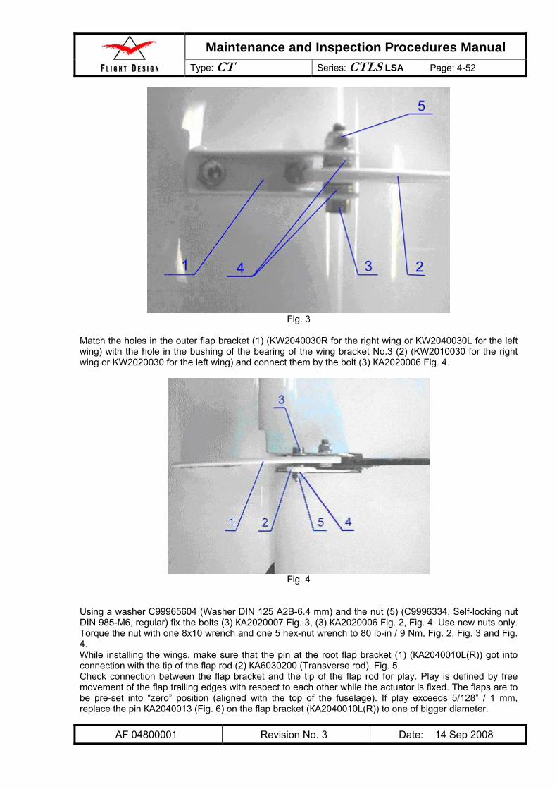
Design task specific training required. To install the wings requires three persons. Prior to installation set the aircraft on the parking brake and remove any obstacle within 16 ft area from the fuselage. Lubricate all metal details with LITOL-24M before connecting: the flap pin KA2040013 (2) (Fig. 5); pins on the wing root rib KA2010301 (1), Fig. 7, Fig. 8; the main bolts KA2000010 (1) Fig. 12.
1) Set each wing with the tongue into the spar box KA1001400 with clearance 0.75-1ft between the fuselage and the wing root rib (Fig. 3); insert the intake fuel line with the connecting pipe (1) to the fuselage.
2) Connect the pitot lines between the wing and the fuselage (for the right wing only). Pay attention not to mix the two pitot lines. One line is clearly marked with a black piece of shrink hose on both ends. Match this line together.
3) Connect the fuel tank vent pipes. Pay attention that the line inside the fuselage root rib boxes does not get kinked.
8) Set the pins of the wing root rib KA2010301 up to the stop into the forward KA1000110 and aft
KA1000101 bushings on the fuselage. Take care that the flap pin KA2040013 gets into the groove of the tip KA6030201 (Fig. 5). Note that the pins can be set properly into the bushings by moving of the wing back and forth (Fig. 9) and up and down (Fig. 10).
Fig. 9
Fig. 10
9) Support the pre-set wing until both wings are installed and fixed by the main bolts КА2000010. 10) Repeat the procedure (except item 2, for the left wing) for the other wing.
11) Match the hole of the spar bushing of the right wing KA2010102 with the hole of the bushing of the left wing KA2010103 from the right side moving the wing up and down (Fig. 9).
Fig. 11
12) Push the main bolts fully in, e.g. set the main bolt KA2000010 (1) into the matched holes of the
bushings KA2010102 and KA2010103 by moving the wing up and down (Fig. 11 and 12).
13) Repeat item 11 for the second main bolt KA2000010. 14) Secure the main bolts with the cap and bolt, e.g. set the caps KA2000013 (1) onto the main bolts
KA2000010 and fix them by bolts М8x35 С9996078А (Fig. 14). Torque value for the main bolts is 200 lb-in / 22,5 Nm.
Fig. 14
15) Match the holes in the tip SMC6 of the rod KA6020050R with holes of the right wing lever
КА6020040R (Fig. 14). 16) Fix the rod KA6020050R (1) in the lever KA6020040R (2) with the bolt М6x30 С9996259А (3).
4.1.2.6 Wing Removal Drain all the fuel from the wings, fuel lines, and gascolator. The process of draining the aircraft should be performed in a ventilated area with fire precautions taken. The rest of the wing removal process goes in reverse to the wing installation process.
4.1.2.7 Verification Required -Make sure the main bolts are properly tight, check torque of the screws. -Make sure the control rod bolts are secured and marked with anti-sabotage lacquer -Make sure the fuel lines are properly secured with hose clamps
4.2 Landing Gear CT is equipped with conventional tricycle landing gear. The main gear legs made of high strength composite material are attached to the main bulkhead located behind the pilot seats. The nose gear is equipped with a shock absorber and attached to the engine mount.
4.2.1 Nose Landing Gear
4.2.1.1 Tools Required Screw driver with header 13 2 pcs Wrench 8x10 1 pcs Wrench 10x13 2 pcs Wrench 17x19 2 pcs Hex-nut wrench 4 1 pcs Hex-nut wrench 5 1 pcs Drill (to drill metal) Ø 0,237 inch / 6,0 mm 1 pcs Brace 1 pcs 34’’ support with padded top 1 pcs Chock 4 pcs
4.2.1.3 General Due to lifting loads being hazardous, two persons are required to remove/install the nose landing gear.
A. Before starting, set the parking brake. Remove cowlings; make sure the tail area is clear. B. Lift the forward fuselage by pushing down the tail at the narrowest part so that the nose wheel is
at least 10’’ off the ground. C. Insert the padded support securely just behind the firewall. NOTE: The top of the support has to be soft to prevent damage of the skin and paint. D. Set the chocks under the wheels to prevent plane’s rolling. E. The nose gear fairing can not be removed without prior removing the nose gear strut.
4.2.1.4.2 Minimum Level of Certification Owner/Pilot
4.2.1.4.3 Visual Inspection 1) The strut and fork for damages, dents, cracks, paint detachment (Fig. 1). Pay specific attention to
welding seam areas. Check for obvious damage to all visible parts each time the fairing is removed (Fig. 1, item 2).
2) The engine mounts for damage, dents, cracks (Fig. 1, item 3). Pay specific attention to welding seam areas. Check all visible surfaces before each flight (inspect engine compartment visually each time the cowlings are removed).
3) The firewall for damage, dents, cracks, delaminating (Fig. 1, item 4). Pay specific attention to the areas where the engine mount is attached to the firewall. Check all visible surfaces each time the cowlings are removed.
4) For all items above, thoroughly inspect with all removable items off at least (cowlings, fairing (Fig. 1, item 2) and so on). In case of a hard landing, inspect right after the landing.
NOTE: If damages are found per items 1 through 4, inform directly Flight Design for inspection
and further instructions.
4.2.1.4.4 Shock Absorber Inspection Shock absorber (Fig. 1) for binding and unusual noises while operating (all three wheels must be on the ground):
• Turn the propeller and set it horizontally. • Push down the propeller by both hands as much as possible. • Release sharply. Make sure the plane returned to original position by the shock absorber. • Repeat for 2-3 times. • If operation is suspected wrong, see sections 4.2.1.5 and 4.2.1.6.
4.2.1.4.5 Fork Inspection Inspect the fork for play, binding and unusual sounds while rotating (Fig. 1, items 3) with the rudder pedals:
• Lift up the nose gear as described in 4.2.1.5. General section B and turn the nose gear right by pedals and then release.
• Turn it to the left and release. • Repeat 2-3 times to each side. • If operation is suspected wrong, see sections 4.2.1.5 and 4.2.1.6.
Make sure there is no play between the pin (KA4010101 Pin) and the slot in KA4010110 Rotating body. Replace the pin (KA4010101 Pin) if necessary – see Chapter 4.2.1.7. Make sure there is no play between the KA4010001 Rocker (Fig. 2) and the KA4010110 Rotating body. Replace if necessary – see Chapter 4.2.1.7. Make sure there is no play between the KA4010001 Rocker (Fig. 2) and the engine mount in vertical direction. Replace if necessary – see Chapter 4.2.1.7.
4.2.1.4.6 Nose Wheel Inspection Inspect:
1. The nose wheel for runout, play, binding unusual sounds while rotating (Fig. 1, item 1) - at least 100h. Lift up the nose gear as described before (4.2.1.5, General section B) and pull the wheel so that it makes 6-8 turns and watch rotation up to stop. If suspected something see sections 4.2.1.5 and 4.2.1.6. 2. Tires for inflation visually before each flight, measure tire pressure (2 bar / 29 PSI) as necessary. If suspected something see section 4.2.1.6. 3. The tire for integrity and height of tread (at least 0,04 inch / 1 mm) – before each flight. If suspected something see section 4.2.1.6. 4. The wheel fairing for integrity (Fig. 1, item 2), secure attachment and foreign objects in the aft part of the fairing – before each flight.
Unscrew the nut C9996334 (Self-locking nut DIN 985-M6, regular) that fixes the bolt C9996064 (Bolt DIN 912 M6x60-8.8) by a 10х13 wrench and hex-nut wrench 5. Slightly rocking and pressing the lever KA4010001 Rocker (Fig. 2), remove the bolt C9996064 and release the lever by holding the nose wheel axle. Remove the fork out of the engine mount, rocking and pushing it down.
4.2.1.5.4 Before Installation Clean the mating surfaces of grease and debris, especially concerns the friction surfaces of the bronze bushings (Fig. 3, item А). Make sure the fork tubes are not bent (the rotating tube in the engine mount, in particular) and check them for dents and cracks. Check bronze bushings on the strut for security, play, integrity (they are to be of correct circular shape and of constant thickness), cracks, dents, nicks and wearing. Check shape of the hole for the bolt C9996064. Check diameter of the hole for the bolt C9996064 that has to be not more than 0.237 inch / 6.0 mm (0.197 inch / 5 mm for replacement strut). Check the bolt C9996064 Bolt DIN 912 M6x60-8.8 for integrity and thread condition. Replace, if necessary. Apply a thin layer of grease (Grease CIATIM-201 GOST 6267-74 (or Aeroshell Grease 6 (SHELL), Unirex S 2 (Esso), Eneryrease LCI, LT 2 (British Petroleum)) to prevent corrosion onto the whole attaching (to the engine mount) surface of the strut; Make sure that there is sufficient grease on the friction surfaces – (Fig. 3, item А).
Fig. 3
4.2.1.5.5 Fork Installation Make sure that all operations from the “Before Installation” section are done! Installation process is a reverse to removal process. Make sure that only new nuts C9996334 (Self-locking nut DIN 985-M6, regular) are used for fixing the bolt C9996064 (Bolt DIN 912 M6x60-8.8) and tightened 80 lb-in / 9 Nm by a 10x3 wrench and hex-nut wrench 5.
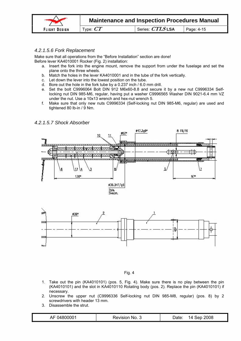
4.2.1.5.6 Fork Replacement Make sure that all operations from the “Before Installation” section are done! Before lever KA4010001 Rocker (Fig. 2) installation:
a. Insert the fork into the engine mount, remove the support from under the fuselage and set the plane onto the three wheels.
b. Match the holes in the lever KA4010001 and in the tube of the fork vertically. c. Let down the lever into the lowest position on the tube. d. Bore out the hole in the fork tube by a 0.237 inch / 6.0 mm drill. e. Set the bolt C9996064 Bolt DIN 912 M6x60-8.8 and secure it by a new nut C9996334 Self-
locking nut DIN 985-M6, regular, having put a washer C9996565 Washer DIN 9021-6.4 mm VZ under the nut. Use a 10x13 wrench and hex-nut wrench 5.
f. Make sure that only new nuts C9996334 (Self-locking nut DIN 985-M6, regular) are used and tightened 80 lb-in / 9 Nm.
4.2.1.5.7 Shock Absorber
Fig. 4
1. Take out the pin (KA4010101) (pos. 5, Fig. 4). Make sure there is no play between the pin
(KA4010101) and the slot in KA4010110 Rotating body (pos. 2). Replace the pin (KA4010101) if necessary.
2. Unscrew the upper nut (C9996336 Self-locking nut DIN 985-M8, regular) (pos. 8) by 2 screwdrivers with header 13 mm.
4. Make sure of integrity of the Polyurethane Damper Elements (Urelastfeder 90 Shores (red 25/10,5 mm. X 20 mm)) (pos. 12). Replace if necessary
5. Clean mating surfaces from remaining grease and debris, specifically care about friction surfaces of the bronze bushings.
6. Inspect the tubes of the fork for bending, dents and cracks. 7. Inspect the bronze bushings for security and play. 8. Inspect the bronze bushings for integrity; they must be of right circular shape and of constant
thickness. 9. Check surfaces of the bronze bushings for cracks, dents, nicks and wearing. 10. Make sure of sufficient lubricant on friction surfaces of the bronze bushings. 11. Make sure of integrity of o-rings C9997730F (O-ring Simrit72, NBR 872, 28.0x5.0) and
C9997730P (O-Ring 8x18x4) and replace, if necessary. 12. Replace the nut C9996336 (Self-locking nut DIN 985-M8, regular) to a new one. 13. Stack the polyurethane damper elements to the pin axis (pos. 4) as follows: support (pos. 6) flat
surface facing the first polyurethane element, 6 polyurethane elements separated each by a washer (pos. 3), support (pos. 6) (flat surface facing the last polyurethane element). See Fig 4.
14. When installing the pack, carefully grease up all sides of each polyurethane element using all-purpose grease. Greasing the elements is very important for the functioning and durability of the device.
15. Assemble the shock absorber by running items 1 through 3 in reverse order. Tighten the nut C9996336 (Self-locking nut DIN 985-M8, regular) 200 lb-in / 22.5 Nm.
4.2.1.6 Nose Wheel
4.2.1.6.1 Type of Maintenance Line
4.2.1.6.2 Minimum Level of Certification Owner/Pilot
Make sure that only new nuts are used! Wheel removal is possible without nose gear fork disassembling.
1) Unscrew the two bolts C9996059 (Bolt DIN 912 M6x30-8.8) by a hex-nut wrench 5 and release the nose wheel fairing.
2) Lift up the fairing along the strut up to the stop. 3) Inspect according to the section III. Make sure of sufficient length of bushings KA4010003 (Bush)
to prevent play, otherwise replace them.
Fig. 6
4) Unscrew the nut C9996338 (Self-locking nut DIN 985-M12, regular), Fig. 6, by two wrenches
17x19 and remove the axle KA4010002 (Wheel axis). 5) Inspect the axle KA4010002 (Wheel axis) for integrity, nicks, dents and cracks, pay specific
attention to the threaded part of it. Replace, if necessary. 6) Inspect the wheel rims for dents and cracks. Replace, if necessary (or suspected necessary). 7) Inspect mounting holes in the wheel rims for bearing, cracks and shape. Replace, if necessary (or
suspected necessary). 8) Check bearings for condition. 9) Inspect the tube for integrity. Inspect the tire for foreign objects. Inspect metal parts of the wheel
contacting the tube for sharp edges and nicks. Apply talcum onto the inner surface of the tire and onto the tube. Replace C9997207D 4.00-4” Unit with tire and tube, for Ultralight 4.00-4 in case of broken integrity, track depth less 0.04 in. / 1 mm or inability to keep necessary pressure within 24h.
10) Wheel installation is reverse to removal. Replace C9996338 (Self-locking nut DIN 985-M12), Fig. 6, to a new one. Secure the screws C9996059 (Bolt DIN 912 M6x30-8.8), Fig. 5, by lock liquid of middle strength Loctite 243.
4.2.2 Main Landing Gear The main landing gear of the CTLS is made from composite materials and is of the cantilever spring type. The cantilever spring ensures harmonic deflection behavior with good damping. The two separate struts (left / right) are mounted in a bearing in the fuselage. This bearing is in the fuselage main frame whence the landing loads are discharged into the structure. The struts are attached to the structure by two bolts at the top ends. A clamp cushioned by a thin layer of rubber at the fuselage exit supports the strut. The fuselage exit is faired to an aerodynamically optimized form. At the bottom of the landing gear strut there is a stub axle to which the main wheels and the brakes are attached. The main wheels have removable fairings.
Fig. 1
Due to lifting loads being hazardous, two persons are required to remove / install the main gear struts.
4.2.2.1 Tools Required Wrench 10х13 2 pcs Wrench 19х24 1 pcs Hex-nut wrench 3 1 pcs Hex-nut wrench 5 1 pcs Hex-nut wrench 6 1 pcs Rubber hammer 1 pcs Support with soft top 34 inch / 850 mm high 1 pcs Support 8 inch / 200 mm high under the main wheel attachments KA4020100L (R) 2 pcs Wheel Chock 4 pcs 8’’ wheel support 2 pcs Wing support 2 pcs
4.2.2.2 Materials Required Lock liquid of middle strength Loctite 243 Lock liquid of high strength Loctite 270 Anti-seize Loctite 8008 Talcum
4.2.2.3 General Before starting, set the parking brake. In addition always place chocks to the nose wheels to avoid rolling of the aircraft in case the brake gets loose or brake lines are opened. Except for main wheel fairing replacement and wheel inspection, all the operations on disassembling parts of the main struts will require dismounting of the brake calipers (Fig. 3), and therefore bleeding and inspection of the brake system upon completion.
4.2.2.4 Inspection
4.2.2.4.1 Type of Maintenance Line
4.2.2.4.2 Minimum Level of Certification Owner/Pilot.
4.2.2.4.3 Visual inspection 1) Inspect the main gear struts for damages, dents, cracks, and paint delamination. 2) Inspect connecting places (left/right) for damages, dents, cracks, and delamination. 3) Check for presence and correct position of the rubber elements located between the outer
landing gear clamps (where the gear leg passes the fuselage) and the gear leg. Missing of these elements leads to loose landing gear fitting with subsequent damages to the landing gear in operation.
4) Check the bulkhead and tunnel made of composites for damages, dents, cracks, delamination at the areas of landing gear attachments.
5) Inspect the main struts for bending, damages, dents, cracks on the surface and especially at the mounting holes areas, integrity and circularity of the mounting holes. Check all visible surfaces before flight.
6) Inspect annually for all stated above with removal of all the parts obscuring (strut fairing and so on) the ones being inspected. Inspect the main wheel attachment for damages, dents, cracks on the surface and especially at the mounting holes areas, integrity and circularity of the mounting holes. In case of hard landing inspect immediately after landing.
If damage is found, contact directly Flight Design for inspection and making decision on further actions.
4.2.2.4.4 Wheel Inspection 1. Inspect the main wheels for runout, play, binding, strange noises for 100 h. Push the wheel so
that it makes 6-8 turns and watch rotation up to stop. 2. Check tire pressure (29 PSI / 2bar). 3. Check tires for integrity and tread depth (at least 0.04 inch / 1 mm). 4. Inspect wheel and strut fairings for integrity and security. If replacement is necessary, refer to
sections 4.2.2.5, 4.2.2.7.
4.2.2.5 Main Wheel Fairing Removal (Replacement)
4.2.2.5.1 Type of Maintenance Line
4.2.2.5.2 Minimum Level of Certification Owner/Pilot
Unscrew the bolt C9996054B (Bolt DIN 912 M6x16-8.8), Fig. 2, by a hex-nut wrench 5. Unscrew three screws C9996162 (Screw ISO 7380 M5x16) by a hex-nut wrench 3, holding the wheel fairing. Remove the fairing. Before installation make sure of integrity and security of the spacer KF32100036 (Spacer). The spacer must be installed with the middle strength Loctite 243 and tightened 49 lb-in (5.5 Nm). Installation is the reverse to removal. NOTE: The bolt C9996054B must be set with lock liquid of middle strength Loctite 243 and tighten 80 lb-in (9 Nm); the screws C9996162 (Screw ISO 7380 M5x16) are to be set with lock liquid of middle strength Loctite 243 and tightened 49 lb-in (5.5 Nm).
4.2.2.6.2 Minimum Level of Certification Owner/Pilot
4.2.2.6.3 Wheel Brake Line Disconnecting Unscrew the nut (Fig. 3, pos. 1) from C9997417E (Fuel L-adapter A-Wek-6/4-1/8-MSv) and disconnect the line C9997205R (6x4 nylon tube) (Fig. 3, pos. 2). Prevent draining of brake liquid out of the hose by plugging it up.
Fig. 3
4.2.2.6.4 Main Wheel Removal Refer to Fig. 4. Fix bolt C9996088 (Bolt DIN 912 M8x90 A4-70) with a hex-nut wrench and unscrew axis KF32100036. Unscrew C9997207T (Nut M20x1.5). Unscrew 4 Self-locking nuts DIN 985-M6, regular (C9996334) by a 10x13 wrench and wrench 6. Remove 2 bolts KF32100037 and 2 bolts KF32100043. Remove the wheel KF32100030 and KF32100031 (Main wheel), pulling it away from the fuselage. Use a rubber hammer, if necessary.
4.2.2.6.5 Before Installation Inspect the bolts for burrs, dents and thread integrity. Replace, if there is any doubt about bolt condition. Inspect the wheel attachment for dents and cracks, mounting holes for integrity and circularity. Replace, if necessary.
4.2.2.6.6 Main Wheel Installation Make installation in the reverse sequence (Fig. 4). Use new self-locking nuts only. Note: Torque moment for nuts: Self-locking nut DIN 985-M6, regular, C9996334 - 9Nm; Nut M20x1.5, C9997207T - 70Nm. Torque moment for bolts: Bolt DIN 912 M8x90 A4-70, C9996088 - 9Nm; Pin for brake disk, C9997205I - 9Nm. For mounting KF32100043, KF32100037, C9996088, C9997205I use "Bonding liquid, middle strength Art.No.3247". Mark all bolt-nut connections with "Enamel Red NC-132К Art.No.09110". Install spacer for camber and toe-in adjusting. Angles of camber and toe-in assure at empty plane with engine installed and wings attached. Spacers: KF32100054, KF3210056 - use for camber adjusting, KF32100055, KF32100057- for toe-in adjusting. Maximum quantity of spacers on each wheel 2 pcs.
4.2.2.7 Removal (Replacement) of Main Strut Fairing
4.2.2.7.1 Type of Maintenance Line
4.2.2.7.2 Minimum Level of Certification Repairman, Light Sport Aircraft-Maintenance (RLSA-M) or higher.
Fig. 5
Take out the main wheel fairing (KF32100010, KF32100011). Refer to section 4.2.2.7. Detach the wheel. Refer to section 4.2.2.8. Detach the C9993230O (Bowlus Maxi Gap Seal Tape 1 1/2'' white) from the fairing KF32100020 and fuselage. Unscrew 2 screws M5x6 (KF32100046). Detach the fairing. Make installation in the reverse sequence. Note: Torque moment for screw M5x6 (KF32100046) – 5Nm For mounting KF32100046 use "Bonding liquid, middle strength Art.No.3247".
4.2.2.8.2 Minimum Level of Certification Repairman, Light Sport Aircraft-Maintenance (RLSA-M) or higher. Flight Design task specific training required.
4.2.2.8.3 Procedure
1. Take out the seats. 2. Set an aircraft on a locating block. 3. Detach a wheel (refer to section 3.3.2.7). 4. Detach the landing gear fairing KF 32100020 (Fig. 6, item 1). 5. In order to detach the support KF32100044 (Fig. 7, item 4), unscrew 2 bolts KF32100042 M6 x
Make installation of the new main gear leg in the reverse sequence. If necessary, refer to sections 4.2.2.7 and 4.2.2.6. Notes:
1. If necessary replace the C9993111B Perbunan gasoline-proof rubber NBR 80 Gas, 2mm (Fig. 6, item 5) using C9993947N TESAFIX 50m x 0.006m.
2. For mounting bolts KF32100043 (Fig. 7, item 1) and KF32100042 (Fig. 6, item 1) use "Bonding liquid, middle strength Art.No.3247".
3. Torque moment for M6 self-locking nuts - 9Nm. 4. Mark all bolt-nut connections with "Enamel Red NC-132К Art.No.09110".
Important: Use only new M6 self-locking nuts (C9996334).
4.2.2.9 Wheel Inspection and Maintenance
4.2.2.9.1 Type of Maintenance Line
4.2.2.9.2 Minimum Level of Certification Repairman, Light Sport Aircraft-Maintenance (RLSA-M) or higher.
4.2.2.9.3 Procedure
Fig. 8
For main wheel inspection (Fig. 8) do the following:
1. Unscrew the bolt KA4020503 (Bolt) by a 19x24 wrench. 2. Unscrew C9997205I (Pins for brake disk) by a 4 hex-nut wrench. 3. Remove the wheel from the axle. 4. Deflate tire before dismantling the rim 5. Unscrew the C9996058 Bolt DIN 912 M6x25-8.8 by a 10x13 wrench and 5 hex-nut wrench. 6. Inspect the rims for dents and cracks. Replace, if necessary. 7. Inspect mounting holes in the rims for bearing, cracks, circularity. Replace if necessary. 8. Inspect bearing for condition and replace if necessary.
9. Inspect the tube for integrity. Inspect the tire for foreign objects. Inspect metal parts of the wheel contacting the tube for sharp edges and nicks. Apply talcum onto the inner surface of the tire and onto the tube. Replace the tire C9997206G (Tire 4.00-6 BfGoodrich 4PR PowerHoby) and the tube C9997206F (Tube 4.00-6 Pn TR13) in case of cracks, height of tread less 0.04in. / 1 mm or inability to keep necessary pressure within 24h.
10. Make sure that the spacer KA4020502 (Distance bushing) is of sufficient length to prevent bearing misalignment. Replace, if necessary.
11. Assembly is a reverse of removal. NOTE: The bolt KA4020503 (Bolt) must be set on lock liquid of high strength Loctite 270, and C9997205I (Pins) on lock liquid of middle strength Loctite 243.
12. Replace the nuts C9996334 (Self-locking nut DIN 985-M6, regular) to new ones and torque the C9996058 Bolt DIN 912 M6x25-8.8 by a 10x13 wrench and 5 hex-nut wrench to 80 lb-in / 9 Nm.
4.2.3.2 Materials Required Lock liquid of middle strength Loctite 243 as required Brake liquid 41 MIL-H-5606 0.88 pint / 0.5 l C9997205R 6x4 nylon tube 130” / 3.3 m (43.31” for each wheel and 43.31” for distribution)
4.2.3.3 Inspection
4.2.3.3.1 Type of Maintenance Line
4.2.3.3.2 Minimum Level of Certification Owner/Pilot
4.2.3.3.3 General To inspect the brake system one person is required. Prior to beginning put wheel chocks each side of the wheels to prevent unintended motion of the aircraft. All the connectors but the connectors A (Fig. 5) are to be tightened up to torque 80 lb-in / 9 Nm and secured by lock liquid of middle strength Loctite 243. The connector A (Fig. 5) is to be tightened up to torque 35 lb-in / 4 Nm, no lock liquid is to be used in this case. Load on the brake control handle and its play can be adjusted by the rod tip C9997006C (Rod end bearing, ext. thread GA5), Fig. 1, b. Prior to adjusting the lock nut C9996333 (Self-locking nut DIN 985-M5, regular) has to be unscrewed by a 8x10 wrench, and a new one tightened to 49 lb-in / 5.5 Nm after adjustment is finished. If brake system lines are broken, drain off brake fluid completely (put a catch can under the wheels to collect drained fluid, and unscrew the connectors A (Fig. 5) on both wheels 1 to 2 turns by a 7x8 wrench. After the repair is completed, carry out all the items of the chapter 4.2.3.6.
4.2.3.3.4 Inspection of Wheel Brakes Check for the necessary level of brake fluid (0.5 of the tank C9997813G Fuel Filter 5/16’’), Fig. 1, a, visually before flight. Check the brake control handle (item 1, Fig. 2) for play (up to 1 16
3 ” / 3cm) prior to using brake, before flight. Check for signs of leakage nearby the brake calipers C9997205U (Caliper), Fig. 1, c, visually before flight. Check the system for operating before flight. Check brake disks for correctness of their shape, dents, bends, nicks, signs of oil and other liquids. Ensure the brake discs have a little amount of free motion along the guide pins (See Fig. 1, d: B - C9997205I Pin for brake disk, A – distance for free motion). Check thickness of brake pads C9997214D (Brake pads for magnesium caliper) (at least 32
1 ” / 1 mm for each (Fig. 1, c). Check tightness of all joints and connections with access panels removed and fairings that block visual inspection – 100 hours.
Remove the access panel KA6010001 (Access Panel) for inspection. For that remove the knobs (item 2, Fig. 2) using a hex-nut wrench 4 from the levers (items 1, Fig. 2) and unscrew the four screws C9996161 (Screw ISO 7380 M5x12).
Check the control lever (items 1, Fig. 2, Fig. 3), brake cylinder KA7030100 (Brake cylinder), and parking brake C9997419A (Fuel valve K-MI-561-1/8-22-II-MSV) (Fig. 2, Fig. 3) for operating. NOTE: to get full access to brake system controls remove the access panel (item 3, Fig. 3) that hides
the brake cylinder KA7030100 (Brake cylinder). Warning: Do not overpressure the parking brake valve by applying too much force to the brake handle.
The parking brake must work after gentle operation already.
Fig. 4
Brake system controls connections are shown at Fig. 4. Note that while installing the brake system lines the tee fitting С9997205Q - that distributes fluid between the left and right wheels must be shifted towards the left wall of the tunnel in order to ensure free access to the check valve C9997257D (Check valve L-RV6-11-1/8-MSv), Fig. 4. Operation of the brake system is based on functioning of KA7030100 (Brake cylinder) (item 3, Fig. 3, Fig. 4), C9997419A (Fuel valve K-MI-561-1/8-22-II-MSV) (Fig. 2, Fig. 3) and C9997257D (Check valve L-RV6-11-1/8-MSv) (Fig. 4). If concerns raised, do the following.
• Inspect the level of brake fluid (a half of tank). • Visually inspect the lines for air bubbles. • Inspect line connections for leaks and damage where they contact the structure. • Inspect the protection PVC hoses (Art No. 3193B) in the places where brake lines go through the
fuselage skin. If necessary replace them with new ones. • Check thickness of the brake pads.
• Inspect the brake disks surface for signs of oil and other liquids. • Replace brake system control parts as follows.
1. For the check valve C9997257D (Check valve L-RV6-11-1/8-MSv), Fig. 4, carry out operations of the chapter IV and check the system.
2. For the parking brake C9997419A (Fuel valve K-MI-561-1/8-22-II-MSV), Fig. 2 and Fig. 3) carry out operations of the chapter IV and check the system.
3. For the brake cylinder KA7030100 (Brake cylinder) (item 3, Fig. 3 and Fig. 4) carry out operations of the chapter IV and check the system.
In case of unsatisfactory operation of the brake system after followed by carrying out all said above operations, immediately contact Flight Design for inspection and making decision on further action.
4.2.3.4 Filling Brake System with Fluid
4.2.3.4.1 Type of Maintenance Line
4.2.3.4.2 Minimum Level of Certification Repairman, Light Sport Aircraft-Maintenance (RLSA-M) or higher.
4.2.3.4.3 Procedure One person is required. Visually check the system for integrity and tightness. Make sure the brake control handle (item 1, Fig. 2 and Fig. 3) is in most forward position. Make sure the aircraft is not set on parking brake, i.e. the valve C9997419A (Fuel valve K-MI-561-1/8-22-II-MSV) (Fig. 2 and Fig. 3) is open and the handle of the valve is aligned to aircraft longitudinal axle. Place a can under the tank (item 1, Fig. 1) C9997813G (Fuel Filter 5/16’’) to collect brake fluid in case of overfilling.
Fig. 5
To fill the brake system do the following.
1. Using a piece of tube C9997205R (6x4 nylon tube) connect a 0.35 pint / 200 ml syringe filled with brake fluid without air bubbles.
2. Unscrew the connector A 1 to 2 turns on the right wheel using a 7x8 wrench (Fig. 5). 3. Fill the lines with brake fluid so that it goes further 4” / 10cm from the tee fitting C9997205Q
(Fig.4), that connects the lines from the right and left wheels, towards the brake cylinder KA7030100 Brake cylinder (item 3, Fig. 3 and Fig. 4).
4. Tighten the connector A (Fig. 5) using a 7x8 wrench up to torque 80 lb-in / 9 Nm). Disconnect the syringe.
5. Totally refill the syringe with the brake fluid with no bubbles and carry out operations 1 through 3 for the left wheel so that C9997813G (Fuel Filter 5/16’’ (item 1, Fig. 1) is ¾ full.
6. Screw in the connector A (Fig. 5) by a 7x8 wrench. 7. Move the brake control handle back and forth 5 to 8 times (items 1, Fig. 2 and Fig. 3). Note if
there are air bubbles in the line nearby the caliper C9997205U (Caliper)
8. Unscrew the connector A 1 to 2 turns by a 7x8 wrench (Fig. 5). 9. Add as more brake fluid as enough to eliminate air bubbles nearby the caliper C9997205U
Caliper. 10. Repeat operations 6 through 9 until full elimination of air in the caliper C9997205U (Caliper) with
pads activated. 11. Screw in the connector A by a 7x8 wrench (Fig. 5). 12. Close the valve C9997419A (Fuel valve K-MI-561-1/8-22-II-MSV), Fig. 2 and Fig. 3, and move
the handle 2 to 3 times back and forth (item1, Fig. 2 and Fig. 3). Note if there are air bubbles in the line nearby the check valve C9997257D (Check valve L-RV6-11-1/8-MSv), Fig. 4.
13. Inspect joints and connections for leaks. 14. Open the valve C9997419A (Fuel valve K-MI-561-1/8-22-II-MSV), Fig. 2 and Fig. 3, sharply. 15. Unscrew the connector A (Fig. 5) 1 to 2 turns by a 7x8 wrench. 16. Add as more brake fluid to eliminate air bubbles nearby the check valve C9997257D (Check
valve L-RV6-11-1/8-MSv) (Fig. 4). 17. Repeat operations 11 through 16 until full elimination of air in the brake system controls. 18. Tighten the connector A (Fig. 5) up to torque 80 lb-in / 9 Nm by a 7x8 wrench. Disconnect the
syringe. 19. Make sure the line is completely filled by fluid, no air bubbles are seen and the capacity
C9997813G (Fuel Filter 5/16’’), item1, Fig. 1, is ¾ full. 20. Make sure the brake disks and pads are dry and clean. 21. Check brakes for operating 2 to 3 times before flight while warming up the engine and taxiing.
4.2.3.5 Brake Pads Replacement
4.2.3.5.1 Type of Maintenance Line
4.2.3.5.2 Minimum Level of Certification Repairman, Light Sport Aircraft-Maintenance (RLSA-M) or higher.
4.2.3.5.3 Procedure
1. Using 5 hex-nut wrench, unscrew the bolts C9997205I (Pin for brake disk), Fig. 5, and release the brake disk that it does not get between the pads.
2. Unscrew two bolts (item B, Fig. 5) attaching the brake pads by a 4 hex-nut wrench. Check that the springs С9997702C (Compression spring 1x8x28.5x8.5) opening the pads all present.
3. Replace the pads and set the spring С9997702C (Compression spring 1x8x28.5x8.5) between them.
4. Tighten two mounting bolts (item B, Fig. 5) of the pads by a 4 hex-but wrench up to torque 49 lb-in / 5.5 Nm. Use lock fluid of middle strength Loctite 243.
5. Install the brake disk. 6. Secure the brake disk tightening the bolts C9997205I (Pin for brake disk), Fig. 5, up to torque 80
lb-in / 9 Nm by a 5 hex-nut wrench. Use lock fluid of middle strength Loctite 243. 7. Make sure the brake disks are dry and clean. 8. Make sure all the lines are filled with fluid, no bubbles are seen, and the capacity C9997813G
(Fuel Filter 5/16’’), item 1, Fig. 1, is ¾ filled. 9. Check brakes for operating 2 to 3 times before flight while warming up the engine and taxiing.
4.3.1 Aileron The ailerons are made of aramid top and bottom skins, carbon web and three glass fiber composite ribs. The aileron is attached to the wing by two hinged brackets. The ailerons are activated via push rods which run from the control stick through the tunnel to the mixer in the baggage compartment behind the main frame. In the mixer the ailerons are super-imposed with the flap controls as the ailerons are deflected when the flaps are set. Control rods run from the mixer upwards behind the main frame where the associated bell cranks on the wing root rib are activated via a torsion shaft and a connecting rod. The following diagram depicts the aileron controls (orange) and flap controls (turquoise) in the fuselage with mixer and with connection to the wings.
The aileron controls have return springs which ensure more harmonic force gradients. These springs are attached to the rear of the main frame and engage in the mixer. Removal or installation of an aileron requires one person. Adjustment of the aileron angles of deflection requires two persons.
4.3.1.1 New design of aileron control system. Design of Aileron and Flap control systems were updated. All elements of the Control systems were installed and starting from the airplane S/N 08-03-05, except for planes 08-03-07, 08-03-08, 08-03-09, 08-03-10, 08-03-11, where the previous system still was installed. During these changes was update flap actuator bracket and aileron droop mixer. Modification of Aileron and Flap control systems see in following photo 1.
4.3.1.3 Materials Required Bonding fluid, middle strength Loctite 243 as required С9993247B Glue Loctite 480 as required Multipurpose plastic grease LITOL-24M ТУ 0254-015-00148820-99 (Retinax EP 2. Alvania EP-2 (SHELL); Alvania Grease R3 (Petroleum Co, Ltd); Mobilgrease MP, Mobilux 3 (Mobil Oil Corp.); Energrease LS 3 (British Petroleum Co.); Beacom 3 (Esso)) as required C9996334 Self-locking nut DIN 985-M6, regular 12 pcs С9997022 Spherical Bearing EGLM 10 pcs
4.3.1.4 General A. Unless otherwise specified the instructions below concern both right and left ailerons. B. To increase (reduce) length of a rod:
1) Release the rod tips, having loosened the locking nut by an 8x10 wrench. 2) Take care that the tips are screwed into the threaded adjuster bushing body at least
5/16” / 8 mm. 3) Unscrew (screw in) the rod tip a half-turn (180°) on each of the rods. 4) Check rod length. 5) Repeat items 2 through 4, if necessary. 6) Tighten the locking nut by an 8x10 wrench, unscrewing it from the tip towards the rod. 7) Note that the nuts C9996334 (Self-locking nut DIN 985-M6, regular) are to be tightened to 80
lb-in / 9 Nm and C9996333 (Self-locking nut DIN 985-M5, regular) to 49 lb-in / 5.5 Nm. C. Set the fuselage so, that fuselage roof is horizontal. Check it by a level that must be
perpendicular to the wing saddle area (root rib).
4.3.1.5 Inspection
4.3.1.5.1 Type of Maintenance Heavy
4.3.1.5.2 Minimum Level of Certification Repairman, Light Sport Aircraft-Maintenance (RLSA-M) or higher.
4.3.1.5.3 Bracket Inspection Inspect the wing brackets for security and play (KW2010030, KW2010040 for the right wing, and KW2020030, KW2020040 for the left wing). Torque the bolts (С9996286Р Bolt DIN 912 M6x35, A2) by a 5 hex-head screwdriver and screwdriver with header 10 in case of play. Use hole A for access to the aft of the wing lower skin.
Inspect the aileron brackets (KW2030010R and KW2030020R for the right wing, or KW2030010L and KW2030020L for the left wing) for play. In case of play torque the bolts С9996221 (Bolt DIN 7991 M5x16 A2) to 49 lb-in. / 5.5 Nm by a hex-nut wrench 3, and bolts С9996286К (Bolt DIN 912 M6x16, A2) to 80 lb-in. / 9 Nm by a hex-nut wrench 5.
4.3.1.5.4 Wing bracket bearings inspection Inspect the bearings (С9997022 Spherical Bearing EGLM) for play. Do not lubricate them with anything. If play exceeds 256
5 ” / 0.5 mm, replace the bearing (С9997022 Spherical Bearing EGLM). For bearing installation use lock liquid Glue Loctite 480. Check if there is KA2010008 bushing (1) in the wing brackets (2) (KW2010030, KW2010040 for the right wing or KW2020030, KW2020040 for the left wing), Fig. 1.
4.3.1.5.5 Rods / Bellcranks inspection Check that the rod tips (Rod end bearing, ext. thread GA) are screwed into the rods on a length of more than 64
15 inch / 6 mm. If this is not the case, try to balance the screwed in length between the rod end bearings on both sides. If this does not give the desired result, the rod must be exchanged against a longer one. Inspect all rod tips for play. Inspect all bellcranks and other parts of the aileron control with bearings for play. If play exceeds 256
5 ” / 0.5 mm, replace the bearing. Play of the control stick tip should not exceed 5/128” / 1 mm. Otherwise inform directly Flight Design USA for inspection and further instructions. Lubricate the bearings with LITOL-24M (Retinax EP 2. Alvania EP-2 (SHELL); Alvania Grease R3 (Petroleum Co, Ltd); Mobilgrease MP, Mobilux 3 (Mobil Oil Corp.); Energrease LS 3 (British Petroleum Co.); Beacom 3 (Esso)) as necessary.
4.3.1.6 Aileron Installation
4.3.1.6.1 Type of Maintenance Heavy
4.3.1.6.2 Minimum Level of Certification Repairman, Light Sport Aircraft-Maintenance (RLSA-M) or higher. Flight Design task specific training required. Put the wing top skin down onto a horizontal surface. Inspect per section 4.3.1.7. Match hole on the root aileron bracket (1) (KW2030010R for the right wing) with hole in the bushing of the bearing of the wing bracket No.3 (2) (KW2010030) and connect them by the bolt (3) КW2020005 (do not fix the bolt by the nut (4) (C9996334, Self-locking nut DIN 985-M6, regular)). Fig. 2. NOTE: the bolt connecting the aileron and the rod tip must not be installed.
Fig. 2
Match hole in the aileron bracket (1) (KW2030020R) with hole in the bushing of the bearing of the wing bracket No.4 (2) (KW2010040), put 4 washers (4) (С9996504, Washer DIN 9021-6.4 mm VZ) between the wing bracket and the aileron bracket and connect them by the bolt (3) КW2020007 (do not fix the bolt by the nut (5) (C9996334, Self-locking nut DIN 985-M6, regular)) Fig. 3.
Using a washer С99965604 (Washer DIN 125 A2B-6.4 mm) and the nut (5) (C9996334, Self-locking nut DIN 985-M6, regular) fix the bolts KA2020005 and KW2020007 (3). Use new nuts only. Torque the nut with two 8x10 wrenches to 80 lb-in /9 Nm, Fig. 2 and with one 8x10 wrench and one 5 hex-nut wrench to 80 lb-in / 9 Nm Fig. 3.
Fig. 4
Apply 1 or 2 drops of Bonding liquid, middle strength Loctite 243 onto the threaded part of the bolt С9996219 (Bolt DIN 7991 M6x35). Set the bearing С9997006А (Rod end bearing, ext. thread GA6) by the bolt С9996219 (Bolt DIN 7991 M6x35 A2) onto the aileron root rib. Use washers С9996565 (Washer DIN 9021-6.4 mm VZ) and С9996504 (Washer DIN 125 A2B-6.4 mm) as shown (Fig. 4). Torque the bolt by a 4 hex-nut wrench to 80 lb-in / 9 Nm.
Unscrew the nut C9996334 (Self-locking nut DIN 985-M6, regular) by a 10 wrench and 5 hex-hut wrench. Disconnect the rod (KA6020030R) from the internal bellcrank. Fig. 5. Connect the rod (3) (KA6020030R) with the bearing (1) (С9997006А, Rod end bearing, ext. thread GA6), that is fixed to the aileron root rib as shown (Fig. 6).
Fig. 6
Connect the aileron rod (1) (KA6020030R) with internal bellcrank (Fig. 5). Engage, but do not tighten the nut on the bolt.
Set the external bellcrank (2) КА6020040 so that the line between the rod (1) attachment hole and bellcrank axle of rotation is perpendicular to the root rib (Fig. 7). At the same time the internal bellcrank must be set so that the line between the rod КW6020010 mounting hole and bellcrank axle of rotation is parallel to the rib of the wing. Otherwise correct internal bellcrank positions by adjusting length of the КW6020030R rod; disconnect the rod КW6020030R from internal bellcrank and aileron and adjust length of the rod per section 4.4.1. B. Take care that the tips are inserted into the КW6020030R rod at least 0.25 inch / 6 mm. Check “zero” position and angles of deflection.
Install the wings (1 and 2) onto the fuselage. Fix them by the main bolts (3) КА2000010. Fig. 8. While installing the wings make sure that the pin in the flap root bracket (1) (КА2040010L for the left wing, KA2040010R for the right wing) gets into slot in the tip of the flap rod (2) КА6030200 (Transverse rod). Fig. 9.
4.3.1.7.2 Minimum Level of Certification Repairman, Light Sport Aircraft-Maintenance (RLSA-M) or higher. Flight Design task specific training required.
4.3.1.7.3 Rigging Aileron “Zero” Position “Zero” position of the ailerons is the position when the ailerons are aligned to the flaps in -6° (-12°) cruise configuration.
1. Set the flaps in –6° (–12°) cruise position. 2. Fix the control sticks (Fig. 10) in neutral position (sticks must be vertical when seen from behind
perpendicular to tube under the pyramid. The fork-rod (Fig. 11) must be in neutral position with respect to the fuselage roof in the spar box area. (the top is set horizontally by a level)
3. Match the holes in the rod tip (С9997006А, Rod end bearing, ext. thread GA6) with the hole in
the bellcrank (2) КА6020040 (Fig. 7). Note that when the external bellcrank (2) КА6020040 is set so that the line between the rod (1) attachment hole and bellcrank axle of rotation is perpendicular to the root rib (Fig. 7), the internal bellcrank must be set so that the line between the rod КW6020010 mounting hole and bellcrank axle of rotation is parallel to the rib of the wing. Otherwise disconnect KA6020050R(L) and change its length per section 4.3.1.6 B.
4. Connect the rod in the fuselage root rib box (1) (КА6020050L for the left wing, KA6020050R for the right wing) with bellcrank (2) (КА6020040L for the left wing, KA6020040R for the right wing) by the bolt (3) КА6020021. Engage the nut (5) (C9996334, Self-locking nut DIN 985-M6, regular) onto the bolt (3), but do not tighten. Fig. 7.
5. Check “zero” position of the ailerons. If the ailerons are not aligned with the flaps, disconnect the rod (КА6020030R for the right wing, КА6020030L for the left wing) from the internal bellcrank КА2010130. (Fig. 7) and reduce length of the rod КА6020030R(L) in case the aileron trailing edge is lower than the flap trailing edge (refer to section 4.3.1.6 B). Otherwise increase length of the rod.
6. Connect the aileron rod КА6020030L (KA6020030R) with the internal bellcrank. Engage, but do not tighten the nut (5) (C9996334, Self-locking nut DIN 985-M6, regular) on the bolt (3) (С9996061, Bolt DIN 912 M6x40-8.8). Fig. 7.
7. Check aileron “zero” position. If the ailerons are not aligned with the flaps repeat items 5 through 6.
4.3.1.7.4 Aileron Deflection Adjustment 1. Aileron deflections are defined in the deflection table. Aileron deflection adjustment follows the same principle in both aileron control variants. 2. Aileron deflection (flaps in position -6º) can be adjusted by changing the length of the rods in the system of aileron control (vertical rods pos. 1 and short rods in the wings). If the length of the vertical rods (pos. 2) is not enough, for the old control system it is possible to use short rods (pos. 5). The rod lengths (pos. 5) must be adjusted equally. 3. In the old system, aileron droop (flaps in position 35º) can be adjusted by changing the length of the short rods (pos. 3, 4). 4. The length of the rods can be adjusted only following chapter 4.3.1.6. 5. After each adjustment check the angles of aileron deflection according to the following procedure.
4.3.1.7.5 Measuring Aileron Deflection Any adjustment of the aileron control system must be documented in an adjustment report. You can find the template starting the nominal values and allowable tolerances in the Appendix of this maintenance manual. Step 1. Set flaps to upper position -6° or -12° (-6° is required for CTLS registered within USA as LSA aircraft). In this position the trailing edges of aileron and flaps must coincide (see photo 1).
Photo 1 Step 2. Put the pattern on the flap (see photo 6). Deflect the aileron in upper position by control stick. Place between markers on the pattern must coincide with the aileron trailing edge (see photo 2). Markers on the pattern define boundary values of maximum deflection angle.
Photo 2 Using ruler instead of deflection template: Measure distance between same corners (lowest or topmost) on the rear edge of the flap and on the aileron (see photo 2.1).
Photo 2.1 Step 3: Deflect the aileron in lower position by control stick. Place between markers on the pattern must coincide with the aileron trailing edge (see photo 3). Markers on the pattern define boundary values of maximum deflection angle.
Photo 3 Using ruler instead of deflection template: Measure the distance between same corners (lowest or topmost) on the rear edge of the flap and on the aileron (see photo 3.1).
Photo 3.1 Step 4. Repeat operations 2 and 3 for the other aileron.
4.3.1.8 Verification of Aileron Installation and Adjustment 1. Inspect per section 4.3.1.7. 2. Check aileron deflection (section 4.3.1.10.1). 3. Tighten the rod tip locking nuts by an 8x10 wrench, unscrewing them from the tip towards the rod
per section 4.3.1.6 B) for all rods that have been re-adjusted. 4. After adjustment, the elements of the ailerons control system must not touch the elements of
fuselage construction and flaps control system elements. 5. Torque bolts with 8x10 wrenches to 80 lb-in / 9 Nm as shown (Fig. 7).
4.3.2 Flaps The flaps are driven by an electrical spindle motor and are activated via the flap control in the lower section of the instrument panel. The desired flap setting is selected with a torque switch. The position indicator will flash as long as the flaps are moving to the desired setting. Once the desired setting has been reached, the position will be constantly illuminated. The flaps may be set at any of the following positions: –12° (-6° for USA registered aircraft), +0°, +15°, +30°, +35°. The spindle motor is integrated into the mixer behind the main frame in the aircraft baggage compartment. It influences the controls mixer, whence the flaps are activated via push rods. Both flaps are directly attached to a torque tube in the fuselage, thus ensuring that they are always deflected symmetrically. The flap servo has an internal load-limiting device which prevents the extension of the flaps at too high airspeeds without causing sustainable damage to the structure. Should the indicator blink constantly when extending the flaps, airspeed should be reduced. If the flaps then extend, the internal load-limiting device was in operation. If extension speed is below the maximum speed for flap extension as given in the handbook, the next Flight Design service station should be contacted. The flap control circuit breaker is to be found directly adjacent to the flap controls. It will pop if the flap servo is continuously over-loaded. As it is a thermal circuit breaker, it can take some time before it can be pushed back in. Note: The CTLS can be safely landed in any flap configuration. Control forces during go-around in the landing configuration have been demonstrated to be
4.3.2.3 General 1. Unless otherwise specified the instructions below concern both right and left flaps. 2. To increase (reduce) length of a rod:
a) Release the rod tips, having loosened the locking nut by an 8x10 wrench. b) Take care that the tips are screwed into the threaded adjuster bushing body at least
15/16” / 6 mm. c) Unscrew (screw in) the rod tip a half-turn (180°) on each of the rods. d) Check rod length. e) Repeat items 2 through 4, if necessary. f) Tighten the locking nut by an 8x10 wrench, unscrewing it from the tip towards the rod. g) Note that the nuts C9996334 (Self-locking nut DIN 985-M6, regular) are to be tightened to
80lb-in / 9 Nm and C9996333 (Self-locking nut DIN 985-M5, regular) to 49 lb-in / 5.5 Nm. 3. Set the fuselage so, that fuselage roof is horizontal. Check it by a level that must be
perpendicular to the wing saddle area (root rib). Installation or removal of the flaps requires one person. Setting of flap deflections requires two persons.
4.3.2.4 Inspection
4.3.2.4.1 Type of Maintenance Line
4.3.2.4.2 Minimum Level of Certification Owner/Pilot
4.3.2.4.3 Bracket Inspection Inspect the wing brackets for security and play (KW2010010, KW2010020 and KW2010030 for the right wing, and KW2020010, KW2020020 and KW2020030 for the left wing). Torque the bolts (С9996286Р Bolt DIN 912 M6x35, A2) by a 5 hex-head screwdriver and screwdriver with header 10 in case of play. Use hole A for access to the aft of the wing lower skin if necessary.
Inspect the flap brackets (KW2040010R, KW2040020R, and KW2040030R for the right wing, or KW2040010L, KW2040020L and KW2040030L for the left wing) for play. In case of play torque the bolts С9996221 (Bolt DIN 7991 M5x16 A2) to 49 lb-in / 5.5 Nm by a hex-nut wrench 3, and bolts С9996286К (Bolt DIN 912 M6x16, A2) to 80 lb-in / 9 Nm by a hex-nut wrench 5.
4.3.2.4.4 Wing bracket bearings inspection Inspect the bearings (С9997022 Spherical Bearing EGLM) for play. Do not lubricate them with anything. If play exceeds 256
5 ” / 0.5 mm, replace the bearing (С9997022 Spherical Bearing EGLM). For bearing installation use Loctite 480. Check if there is KA2010008 bushing (1) in the wing brackets (2) (KW2010010, KW2010020 and KW2010030 for the right wing, and KW2020010, KW2020020 and KW2020030 for the left wing), Fig. 1.
4.3.2.4.5 Rods / Bellcranks inspection Check that the rod tips (Rod end bearing, ext. thread GA) could be inserted into the rods more than 64
15 inch / 6 mm. Change the rod, if negative. Inspect all rod tips for play. Inspect all bellcranks and other parts of the flap control with bearings for play. If play exceeds 256
5 ” / 0.5 mm, replace the bearing. Lubricate the bearings with LITOL-24M (Retinax EP 2. Alvania EP-2 (SHELL); Alvania Grease R3 (Petroleum Co, Ltd); Mobilgrease MP, Mobilux 3 (Mobil Oil Corp.); Energrease LS 3 (British Petroleum Co.); Beacom 3 (Esso)) as necessary.
4.3.2.5 Flap Installation
4.3.2.5.1 Type of Maintenance Heavy
4.3.2.5.2 Minimum Level of Certification Repairman, Light Sport Aircraft-Maintenance (RLSA-M) or higher. Flight Design task specific training required.
4.3.2.5.3 Procedure Match the hole in the root flap bracket (1) (KW2040010R for the right wing, or KW2040010L for the left wing) with the hole in the bushings of the bearing of the wing bracket No.1 (2) (KW2010010 for the right wing, or KW2020010 for the left wing) and connect them by the bolt (3) КА2020006 (but do not fix the bolt by the nut (5) (C9996334, Self-locking nut DIN 985-M6, regular), Fig. 2.
Fig. 2
Match the holes in the flap mid bracket (1) (KW2040020R for the right wing or KW2040020L for the left one) with the hole in the bushing of the bearing of the bracket No.2 (2) (KW2010020 for the right wing or KW2020020 for the left wing), put four washers (4) (С9996565, Washer DIN 9021-6.4 mm VZ) between the flap bracket and wing bracket (2 from one side of the wing bracket and 2 from other one) and connect them (brackets) by the bolt (3) КА2020007 (but do not fix the bolt by the nut (5) (C9996334, Self-locking nut DIN 985-M6, regular). Fig. 3.
Match the holes in the outer flap bracket (1) (KW2040030R for the right wing or KW2040030L for the left wing) with the hole in the bushing of the bearing of the wing bracket No.3 (2) (KW2010030 for the right wing or KW2020030 for the left wing) and connect them by the bolt (3) КА2020006 Fig. 4.
Fig. 4
Using a washer С99965604 (Washer DIN 125 A2B-6.4 mm) and the nut (5) (C9996334, Self-locking nut DIN 985-M6, regular) fix the bolts (3) КА2020007 Fig. 3, (3) КА2020006 Fig. 2, Fig. 4. Use new nuts only. Torque the nut with one 8x10 wrench and one 5 hex-nut wrench to 80 lb-in / 9 Nm, Fig. 2, Fig. 3 and Fig. 4. While installing the wings, make sure that the pin at the root flap bracket (1) (КА2040010L(R)) got into connection with the tip of the flap rod (2) КА6030200 (Transverse rod). Fig. 5. Check connection between the flap bracket and the tip of the flap rod for play. Play is defined by free movement of the flap trailing edges with respect to each other while the actuator is fixed. The flaps are to be pre-set into “zero” position (aligned with the top of the fuselage). If play exceeds 5/128” / 1 mm, replace the pin КА2040013 (Fig. 6) on the flap bracket (КА2040010L(R)) to one of bigger diameter.
4.3.2.6.2 Minimum Level of Certification Repairman, Light Sport Aircraft-Maintenance (RLSA-M) or higher. Flight Design task specific training required.
4.3.2.6.3 Rigging “Zero” Position of the Flaps “Zero” position is the position of the flaps when the top skin of the flaps is aligned with the top of the fuselage. If the flaps are not synchronous (at the “zero” position one is higher than another), adjust the flap rod КА6030200 (Transverse rod) as follows.
1) Unscrew the lock-nut C9996332 (Self-locking nut DIN 985-M4, regular) by a 7 wrench towards the head of the bolt and release the bolts C9996026 (Bolt DIN 912 M4x 20-8.8), Fig. 7.
2) Unscrew the bolts C9996026 (Bolt DIN 912 M4x20-8.8) 5 turns from the flange of the flap rod KA6030220 (Transverse rod tube, left) by a 3 hex-nut wrench. Fig. 7.
3) Unscrew the nuts C9996333 (Self-locking nut DIN 985-M5, regular) from the bolts С9996042 (Bolt DIN 912 M5x45-8.8) by an 8 wrench and 4 hex-nut wrench. Fig. 7.
4) Turn KA6030210 (Transverse rod tube, right) and KA6030220 (Transverse rod tube, left) with respect to each other so that both flaps are aligned to the top of the fuselage.
5) Fix position of the bolts С9996042 Bolt DIN 912 M5x45-8.8 with respect to the KA6030220 (Transverse rod tube, left) by the bolts C9996026 (Bolt DIN 912 M4x20-8.8). The bolts C9996026 (Bolt DIN 912 M4x20-8.8) are to be screwed into the flange of KA6030220
(Transverse rod tube, left) by 3 hex-nut wrench up to bolts С9996042 (Bolt DIN 912 M5x45-8.8). Fig. 7.
Fig. 7
6) Tighten the nut C9996333 (Self-locking nut DIN 985-M5, regular) on the bolt С9996042 (Bolt
DIN 912 M5x45-8.8) by an 8 wrench and 4 hex-nut wrench. Use only new nuts. Put the washer С9996503 under the nut C9996333 (Self-locking nut DIN 985-M5). Repeat for all bolts. Fig. 5.
7) Set the flap position indicator to zero. 8) Inspect connection of the tip KA6030201 and the flap rod (КА6030210 and КА6030220,
Transverse rod tube) for play. In case of play replace the rivets (3) (С9996653 Stainl. steel rivet A2 4x11.5) to next bigger ones (Fig. 8). Eventually diameter of the rivets should not exceed
2565 ” / 0.5 mm. If it would, replace the tubes (КА6030210 and КА6030220, Transverse rod tube) and the tip КА6030201.
Flap deflection can be adjusted by the flap control panel. Check flap angle of deflection after each adjustment by means of electronic level.
1. Connect printed circuit board (PCB) connectors with corresponding headers of the flap actuator control (Control Card MT-10) wiring harness (Fig. 9).
2. Connect auxiliary control switches SW1 and SW2 to corresponding connectors at the PCB for programming.
3. Set the flap into required position by SW2 using a level. Set the digital screen indication corresponding to the value at the level by SW3.
4. Press SW1 to input data into the PCB memory. If the operation has been performed correctly the display shows the value set by SW3.
5. Move the flap by SW2 to the next required position using a level. Change the value at the screen by SW3 according to the value at the level. Press SW1 to save settings into the memory.
6. Repeat the process for each of the flap positions. 7. If you cannot adjust (set) max angles of deflection (the rod of the flap actuator takes the end
position), this problem could be solved by adjusting the length of the rod of flap control. The length of the rod can be adjusted only following the item 4.4.1.5.
8. After rigging all flap positions turn off the circuit breaker 25A. 9. Remove the switches SW1 and SW2. 10. Turn the circuit breaker 25A on. 11. If the instruction has been performed correctly the flaps will take their predefined positions.
4.3.2.6.5 Measuring Flap Deflection Any adjustment of the flap control system must be documented in an adjustment report. You can find the template starting the nominal values and allowable tolerances in the Appendix of this maintenance manual. Step 1. Set flaps in zero position.
Step 2. Put the level on upper surface of the flap (see photos 1 and 2) and note the measured value. Repeat this operation for the second flap.
Photo 1 Photo 2 Step 3. Set flaps to negative (-12° or -6° for USA registered LSA aircraft) Put the level on upper surface of the flap in the same place than before (see photo 3). Note down the detected angle. Repeat this operation for the second flap.
Photo 3 Step 5. The difference between the noted zero deflection value and the negative deflection value provided the angle of defvlection for each individual flap. Using ruler instead of deflection template: Measure distance between same corners (lowest or topmost) on the rear edge of the flap and on the rear edge on the flap tip on the fuselage (see photo 3.1).
Photo 3 Step 6. Set flaps to maximum positive deflection (+35°). Step 7. Put the level on the upper surface of the flap in the same place that point 2 (see photo 4). Note down the detected angle. Repeat this operation for the second flap.
Photo 4 Step 8. The difference between the noted zero deflection value and the negative deflection value provided the angle of defvlection for each individual flap. Using ruler instead of deflection template: Measure distance between same corners (lowest or topmost) on the rear edge of the flap and on the rear edge on the flap tip on the fuselage (see photo 5 and 6).
4.3.2.7.2 Minimum Level of Certification Repairman, Light Sport Aircraft-Maintenance (RLSA-M) or higher.
4.3.2.7.3 Procedure Tools required: Screwdriver 1 pcs Inspection of the up limit microswitches С9997198B (Miniature switch). Fig. 10.
Fig. 10
1. Set the flaps in 35° position. 2. Set the flap control switch in the flap max up position. 3. While the actuator is moving press the up limit switch by a screwdriver. The actuator must stop
then. 4. Release the up limit switch. The actuator must move up to the flap max up position. 5. Replace the Microswitch С9997198B (Miniature switch), if it does not work per items 3 and 4.
Inspection of the down limit switch (Fig. 10):
1. Set the flaps in the flap max up position (-6° or -12°). 2. Set the flap control switch in 35° position. 3. While the actuator is moving press the down limit switch by a screwdriver. The actuator must stop
then. 4. Release the up limit switch. The actuator must move down to 35° position. 5. Replace the Microswitch С9997198B (Miniature switch), if it does not work per items 3 and 4.
4.3.3.3.2 Minimum Level of Certification Required Repairman, Light Sport Aircraft-Maintenance (RLSA-M) or higher.
4.3.3.3.3 Procedure Set the plane on parking brake. Ensure good access to the rear part of the fuselage. Match the hole in the bearing of the bracket КА3020030 (1) with the pin КА3020022 (2) of the rudder lower support КА3020020 (3). Match the hole of the slider bearing MFM-0610-06 (4) of the upper bracket КА3020010 (5) with the pin КА3020512 (6), Fig. 1. Let down the rudder along the matched holes ad pins. Turn the rudder by hand right up top the stop and set the nut DIN 985 M6 (7) onto the pin КА3020020 (2). Tighten the nut by a wrench 8x10. NOTE: the rudder must be installed to the aircraft prior to stabilator installation, due to accessibility reasons.
Turn the rudder left up to the stop and set the rudder left cable (1). Prior to that the bushings КА6050001 (2) are to be installed from both sides of the thimble and tightened by the screw DIN 7991 М6х30-8.8 (3) to the rudder lower support КА3020020 (4) using a hex-nut wrench 4. Use lock liquid of middle strength Loctite 243 for the screw.
4.3.3.4.2 Minimum Level of Certification Repairman, Light Sport Aircraft-Maintenance (RLSA-M) or higher. Flight Design task specific training required.
Fig. 3
Rudder deflection angles are defined by the stops KA4010004 (Fig. 3). Distance between the plate with a hole for the steering rod on the engine mount and the front edge of the stop has to be about 3/4inch / 20 mm. The nose wheel has to be aligned along the aircraft and the pedals are to be leveled.
To adjust rudder deflection to the right: 1) Use hex-nut wrench 5 to unscrew 2-3 turns the bolt C9996057 DIN 912 M6x20-8.8 fixing the stop
KA4010004 on the right rod. 2) Move the stop KA4010004 towards the cabin 0.08-0.16 inch / 2-4 mm. 3) Fix the stop KA4010004 by the screw C9996057 DIN 912 M6x20-8.8. 4) Check angles of deflection (Fig. 4). 5) Repeat items 1 through 4 if necessary. 6) Set the bolt C9996057 DIN 912 M6x20-8.8 using lock liquid of middle strength Loctite 243 7) To reduce angle of deflection to the right move the stop KA4010004 on the right rod
KA4010400R. The rest of the process repeats items 1 and 3 through 6. To change angle of deflection to the left repeat items 1 through 7 for the stop on the left rod KA4010400L.
Fig. 4
4.3.3.4.3 Measuring Rudder Deflection Any adjustment of the flap control system must be documented in an adjustment report. You can find the template starting the nominal values and allowable tolerances in the Appendix of this maintenance manual. Step 1. Put rudder to neutral deflection. Step 2. Install the template to measure rudder deflection angle (see photos 1, 2, 3)
Photo 3 Step 3. Deflect the rudder to left (right) side by pushing the pedals up to the stop. Deflection angle can be read from the template. Using ruler instead of measuring template: Position a pointer marking the rear lower edge of the rudder in the neutral position. Then deflect rudder by pushing the pedals up to the stop and measure distance between pointer and deflected rear edge of the rudder (see photos 4)
After all operations listed above are completed, tension of the rudder control cables has to be checked. The required value is 25.9 ± 0.55 lbs / 11.75 ± 0.25 kgf. There exist coarse and fine adjustments. Make sure that while checking the nose wheel and the rudder are in neutral position (aligned with the longitudinal axle of the plane) and the pedals are leveled.
4.3.3.4.6 Fine Adjustment Fine adjustment can be performed by the nose wheel steering rods. To increase tension:
1. Release the rod male rod end C9997006B (Rod end bearing, ext. thread GA8), having loosened the locking nut C9996334 Self-locking nut DIN 985-M6, regular by a 10x13 wrench and unscrewed the screws C9996218 Bolt DIN 7991 M6x30-8.8 by a hex-nut wrench 4 from the steering lever arm KA4010001.
2. Check that the male rod end C9997006B (Rod end bearing, ext. thread GA8) could be threaded into the rod KA4010400L (R) Rod, left (right) more than 64
15 inch / 6 mm.
3. Unscrew the male rod end C9997006B (Rod end bearing, ext. thread GA8) a half-turn (180°) on each of the rods.
4. Preliminarily fix the rods KA4010400 L (R) on the KA4010001 Rocker by the screws C9996218. 5. Check rudder cables tension (11.75 ± 0.25 kgf). 6. Repeat items 1 and 3 through 5, if necessary. 7. Tighten the nuts C9996334 by a 10x13 wrench, unscrewing them from the tip towards the rod.
Make sure that the flat of the tip is vertical. 8. Unscrew the C9996218 screws and set with Loctite 243 by a hex-nut wrench 4.
Fig. 9
To reduce control cable tension repeat items 1 and 3 through 8, having reversed rotation of the male rod end C9997006B (in the item 3). Note that the same action can be performed with the tips on the other end of the rod KA4010400L (R) Rod, left (right).
4.3.3.4.7 Coarse Adjustment If failed with fine adjustment, coarse adjustment by the threaded adjuster bushings C9997080 Turnbuckle Bluewave M6 (Fig. 10, item 1) has to be done.
1. Look the way the threaded adjuster bushing is secured by the safety wire. Remove the safety wire.
2. Release the tips (Fig. 10, item 2), having loosened the locking nut (Fig. 10, item 3) by a 10x13 wrench.
3. Take care that the tips are inserted into the threaded adjuster bushing body at least 6415 inch / 6
mm. 4. Unscrew the tips half-turn on each threaded adjuster bushing. 5. Check rudder cables tension (11.75 ± 0.25 kgf). 6. Repeat items 4-5, if necessary. 7. Tighten the nuts (Fig. 10, item 3) by a 10x13 wrench unscrewing them from the tip towards the
threaded adjuster bushing. 8. Lock the threaded adjuster bushing by safety wire.
To increase cables tension, perform items 1 through 8, having reversed tip rotation for the operation 4.
4.3.3.5 Verification of Rudder Installation and Adjustment 1. Set the nose wheel along the longitudinal axle of the plane.
a. Make sure the right and left pedals are on the same line. b. The rudder must be in neutral position, along the plane axle. c. The aircraft must run straight on a plane surface
2. verify deflection angles following chapter 4.3.3.6.1 3. Lift up the front of the plane so that the nose wheel is off the ground. Deflect the rudder by the
pedals to the left. Release the pedals and the rudder and nose wheel must return to the neutral position by the returning mechanism. Check the same for the right deflection. Note that unsatisfactory functioning of the returning mechanism may be the result of excessive tension of the rudder control cables.
4.3.4 Stabilator CT empennage consists of a fin with a rudder and all moving horizontal tail called stabilator. The fin makes up a one piece composite structure with the fuselage and therefore is not considered within this section. Rudder inspection and maintenance is described in section STRUCTURAL CONTROL SURFACES. The CTLS has a drag-optimized stabilator with an anti-tab. It is attached to a fuselage-mounted stabilator pivot bearing. An individually matched counter-weight mass with which the stabilator is completely mass-balanced is also attached to this bearing. The anti-tab on the trailing edge of the horizontal tail covers 90% of the elevator span. It is aerodynamically optimally attached to the fin by an elastic composite hinge. It is activated through kinematical coupling when the elevator is deflected. In this way the anti-tab deflects n the same direction as the elevator, thus improving elevator effectiveness and generating a tangible force on the control stick. Warning: When dismounted or when the controls are disconnected, the anti-tab
must never be pushed beyond normal operating limits as this causes damage to the elastic hinge. We recommend that the trim tab be covered with an edge guard or sticky tape be attached to the outside edges to prevent inadvertent movement.
The elevator is activated via a special push-pull cable that runs through the tunnel and along the fuselage floor. This push-pull cable aligns itself to the fuselage and does not require specific regular maintenance.
4.3.4.2 Parts and Materials Required Multipurpose plastic grease LITOL-24M ТУ 0254-015-00148820-99 (Retinax EP 2. Alvania EP-2 (SHELL); Alvania Grease R3 (Petroleum Co, Ltd); Mobilgrease MP, Mobilux 3 (Mobil Oil Corp.); Energrease LS 3 (British Petroleum Co.); Beacom 3 (Esso)), Aeroshell Grease 6: as required
4.3.4.3 General Set the plane on parking brake and ensure good access to the tail of the aircraft. Inspect metal parts and especially welding seams for cracks and dents. Inspect fasteners and axles for nicks and their threads for condition. Ensure only new self-locking nut DIN 985 are used. Check if the sheave is greased enough. Ensure the free motion of the sheave on the axle. Inspect composite parts for cracks, paint delamination, and mounting holes for ovaling where bolts, pivots and bearings are attached. If found, contact Flight Design for making decision on further inspection and maintenance.
4.3.4.4 Stabilator Installation and Removal
4.3.4.4.1 Type of Maintenance Heavy
4.3.4.4.2 Minimum Level of Certification Repairman, Light Sport Aircraft-Maintenance (RLSA-M) or higher.
4.3.4.4.3 Procedure The stabilator is attached to the fuselage by means of the bracket (3 – Fig.1) that rotates on axle KA3010001 (Stabilizer axis of rotation) installed into bearings C9997025 (Bearing SKF 608-2RZ) in the fuselage (Fig. 1).
One person is needed to install the stabilator. Prior stabilator installation, check it for balancing out of fuselage as follows.
1. Install the stabilator bracket with balancer KА3010120 (pos.1) onto the stabilator KA3010200 (Fig. 1). Make sure the trim tab is installed on the stabilator, the control rods КA6060010 (Rod) are connected to the trim tab, the stabilator bracket is equipped with trim tab bell crank КА6060100 and sheave (pos.2).
2. Match holes (pos.3) in the bracket with holes in the upper and the lower skins of the stabilator. 3. Secure the bracket by bolts C9996259N (Bolt DIN 931 M6x110-8.8)
4. Inspect stabilator balance as follows. Set the stabilator so that it can revolve on its axis under its own weight. If the upper skin does not align horizontally when stopped, correct balancing (refer to 4.2.1.8).
5. Remove the bracket from the stabilator. This verification strongly recommended in any case when for the system stabilator – counterweight with bracket – trim tab the changing of any of the following components is possible: the weight of any component or position of the center of gravity for any component. To verify correctness of the stabilator balance, mount the stabilator on the fuselage in order as follows:
1. Check lock rings C9997032 (Lock ring DIN 472-22x1) (Fig. 2) that secure the bearings C9997025 (Bearing SKF 608-2RZ) on both sides of the fuselage are present. Check inner cage of the bearings C9997025 for free rotation. Replace bearings, if necessary.
Fig. 2
2. Lubricate the axle of rotation KA3010001 by CIATIM-201 (or Aeroshell Grease 6 (SHELL), Unirex
S 2 (Esso), Eneryrease LCI, LT 2 (British Petroleum)). Make sure that the threaded parts of the axle are not lubricated.
3. Install the bracket KA3010120, on the fuselage as follows. Match holes in the bracket with holes in the bearings C9997025. Insert the axle KA3010001through the left hole in the bracket, hole in the left bearing C9997025, spacer KA3010002, right bearing C9997025, and right hole in the bracket KA3010120.
4. Ensure that threaded parts of the axle КA3010001 are not lubricated. Secure the axle by new nuts C9996336 (Self-locking nut DIN 985-M8) and torque to 200 lb-in / 22.5 N*m using two 8x10 wrenches.
5. Install the stabilator KA3010200 (Fig. 1) into the bracket КА3010120 by matching holes (pos.3) in the bracket with holes in the top and bottom skins of the stabilator.
6. Set the bolts C9996259N (Bolt DIN 931 M6x110-8.8) throw the matched holes in the bracket КА3010120 and stabilator skins, put washers C9996504 Washer DIN 125 A2B-6.4 mm, and tighten them by the nuts C9996334 (Self-locking nut DIN 985-M6, regular) using two 8x10 wrenches to torque 80 lb-in / 9 N*m. Make sure that the heads of the bolts are on the top of the stabilator.
7. Check balancing of the stabilator, i.e. after some rotation around the axle KA3010001 the stabilator KA3010200 returns to horizontal position. If the top skin does not stabilize at horizontal position, remove the bracket and correct the balancer (refer to 4.2.1.8).
8. Inspect stabilator “cross incidence” with respect to the fuselage roof (set the level across the fuselage first on the stabilator skin behind the bracket, then on the roof nearby the spars. The difference should not be more then 0.5°. Otherwise do the following. • Remove the stabilator from the bracket. • Using a hex-nut wrench 3 and 8x10 wrench loosen the body KA3010011 Bearing body, by
taking the bolts C9996207 Bolt DIN 7991 M5x16-8.8 out either from one side of the fuselage, or from both, depending on stabilator angle of “cross incidence”.
• Correct stabilator “cross incidence” using eccentricity of the KA3010011 Bearing bodies. • Attach the bearing body KA3010011 (Bearing body) by bolts C9996207 Bolt DIN 7991
M5x16-8 nuts (during adjustment it is allowable to use non- self-locking nuts, which have to be replace for final installation).
• Install the stabilator into the bracket and check angle of “cross incidence” with respect to the fuselage roof.
• Repeat described above operations, if necessary, to get the roof and stabilator parallel (The difference should not be more then 0.50)
• Secure KA3010011 Bearing bodies by tightening new nuts C9996333 (Self-locking nut DIN 985-M5) to torque 94 lb-in / 5,5 N*m on bolts C9996207 (Bolt DIN 7991 M5x16-8.8).
9. Following Fig. 3 stretch the safety Bowden cables (pos. 1) and press them out by shrinking hose, art. 3172G, in the places of connection with Stabilizer bracket (pos. 2).
10. Find the middle of the trim tab cable (d=1,5 mm, l=8,0 m). Put ends of the cable on the sheaves (pos. 4) and turn each end around its slot (pos. 5) of the sheave 1,5 times in the opposite directions; then insert them into the safety Bowden cables.
11. Insert the safety Bowden cables with trim tab cables into the holes of the frame 3. 12. Mount the stabilizer bracket (pos. 3) on the fuselage. 13. Stretch the trim tab rods in the tale part of the fuselage through one of the miniblocks (pos. 6). 14. Set the thimble (2 mm) on the trim tab rods, connect the free part of the rods with main part by
flat clip DUPLEX, 1.4401 for 3 mm cable. 15. With the help of turnbuckles (pos. 7) connect the trim tab rods with the trim tab rods stretching
from the throttle box (pos. 8). 16. Tighten the cables by turnbuckles. 17. Attach two trim tab control rods to two brackets on the rear wall of the fuselage. 18. Connect trim tab control rods KA6060010 (Rod) with an 8x10 wrench and 4 hex-nut wrench.
Tighten the nuts C9996333 (Self-locking nut DIN 985-M5) to torque 49 lb-in / 5.5 N*m. Make sure that rod tips C9997006C (Rods end bearings, ext. thread GA5) are secured by C9996333 (Self-locking nut DIN 985-M5) to torque 49 lb-in / 5.5 N*m).
19. Using a bolt C9996060 Bolt DIN 912 M6x35-8.8 connect to rod tip C9997004 (Rod end bearing, int. thread SI6E) to the stabilator bracket B3010120. Tighten the nut C9996334 (Self-locking nut DIN 985-M6, regular) using two 10x13 wrenches to torque 80 lb-in / 9 N*m) (Fig. 2).
4.3.4.5.2 Minimum Level of Certification Repairman, Light Sport Aircraft-Maintenance (RLSA-M) or higher. Flight Design task specific training required.
Fig. 5
Stabilator deflection can be adjusted by bushings КА6040007 Bushes, Fig. 5. Unscrew 2-3 turns the lock nuts С9996334 by two 10x13 wrenches to unlock the bushing КА6040007 (Bushes) for adjusting. Stabilator deflection down:
• to increase angle of deflection down screw the aft bushing КА6040007 Bush (Fig. 5) from КА6040008.
• to reduce angle of deflection down screw the aft bushing КА6040007 Bush (Fig. 5) onto КА6040008.
• as needed deflection is set, lock the bushing КА6040007 Bush by the nut C9996334 (Self-locking nut DIN 985-M6) tightening it by 10x13 wrench to 80lb-in / 9 N*m.
• to increase stabilator deflection up screw the forward bushing КА6040007 Bush (Fig. 5) from КА6040008;
• to reduce stabilator deflection up screw the forward bushing КА6040007 Bush (Fig. 5) onto КА6040008.
• As needed deflection is set, lock the bushing КА6040007 Bush by the nut C9996334 (Self-locking nut DIN 985-M6) tightening it by 10x13 wrench to 80lb-in / 9 N*m.
4.3.4.5.3 Measuring Stabilator Deflection Any adjustment of the flap control system must be documented in an adjustment report. You can find the template starting the nominal values and allowable tolerances in the Appendix of this maintenance manual. Step 1: Set stabilator to neutral. Neutral positioon is achieved when the stabilizer leading edge coincides in angle with the fuselage. (photo 1).
Photo 1 Step 2. Put the level on upper surface of the stabilator (see photos 2 and 3). Set digital indication to zero or note down detected value. Hold the level in the same place (don’t move) during all measurements.
Photo 3 Step 3. Deflect the stabilator with the control stick control stick up to forward (rearward) stop the stick. Note detected values and determine deflection in refernce to the value read at neutral deflection (see photos 4 and 5).
Photo 4
Photo 5 Using ruler instead of scale: Set two coinciding markings on the stabilator and on the fuselage. Deflect the stabilator and measure the distance (see photos 6)
4.3.4.5.4 Measuring of Trim Tab Deflection and Adjustment Attention: Trim tab deflection can be adjusted only after stabilator deflection is set correctly. Trim tab angles of deflection can be adjusted by changing of length of the trim tab control rods КА6060010 (Fig. 6). To change angle of trim tab deflection, unlock rod tip C9997006C (Rod end bearing, ext. thread GA5) by screwing the nut C9996333 (Self-locking nut DIN 985-M5, regular) towards the tip using an 8x10 wrench. Then by screwing C9997006C (Rod end bearing, ext. thread GA5) into or out of the rod КА6060010 adjust angles of deflection as required (Fig. 3). Upon completion of adjusting tighten the nut C9996333 (Self-locking nut DIN 985-M5) to 49lb-in / 5.5 N*m by screwing it towards the tip. Any adjustment of the flap control system must be documented in an adjustment report. You can find the template starting the nominal values and allowable tolerances in the Appendix of this maintenance manual. Step 1: Set stabilator to neutral (see chapter 4.3.4.7.1) Step 2: Set trim wheel to neutral. Step 3: Apply deflection template and verify neutral deflection of trim tab (Photo 1)
Photo 1 Using ruler instead of measuring template: Apply a pointer from the upper surface of the stabilator by setting a spacer to the upper stab surface right upfront of the elastic hinge. Measure distance between pointer and upper corner of the trim tab. Subtract the thickness of the spacer to obtain the deflection value (see photo 2).
Photo 2 Step 4: Select maximum tail heavy trim. Determine deflection of trim tab with stabilator in neutral. Step 5: Deflect stabilator nose up. Determine deflection of trim tab. Step 6: Select maximum nose heavy trim. Determine deflection of trim tab with stabilator in neutral. Step 7: Deflect stabilator nose down. Determine deflection of trim tab.
4.3.4.6.2 Minimum Level of Certification Repairman, Light Sport Aircraft-Maintenance (RLSA-M) or higher. Flight Design task specific training required.
4.3.4.6.3 Procedure In case if balancing of the stabilator is necessary (replacement, repairing surface of the stabilator \ trim tab or changing stabilator bracket), it should be done by means of change of the balancer weight in small increments continuously checking balance. While checking balance, the 6 bolts (Fig. 6, pos. A) have to be screwed in, but not tightened. The stabilator, bracket and axle are to be set on some supports so, that the stabilator could freely wobble around the axle of rotation.
• To reduce balancer weight Screw out the 6 bolts pos. A. Take off the necessary quantity of the lead fraction from the inside of the balancer (Fig. 6, pos. B) and check balance with the bracket installed onto the stabilator. Upon completion tighten the 6 bolts to 200 lb-in / 22.5 N*m using the lock liquid of middle strength Loctite 243.
• To increase balancer weight Screw out the 6 bolts (Fig. 6, pos. A) Add the necessary quantity of lead fraction inside the balancer (Fig. 6, pos. B). After balance is set, put epoxy resin inside the balancer to fill empty space. Tighten the 6 bolts pos. A to 200 lb-in / 22.5 N*m using the lock liquid of middle strength Loctite 243
4.3.4.7 Verification of Stabilator Installation and Adjustment Check stabilator deflection per section 4.2.1.7. Check trim tab deflection per section 4.2.1.7. For checking use template from Appendix I. Check push-pull cable attachments C9997092 (Push-pull cable TIPO 70), Fig. 7, for presence of grease Multipurpose plastic grease LITOL-24M ТУ 0254-015-00148820-99 (Retinax EP 2. Alvania EP-2 (SHELL); Alvania Grease R3 (Petroleum Co, Ltd); Mobilgrease MP, Mobilux 3 (Mobil Oil Corp.); Energrease LS 3 (British Petroleum Co.); Beacom 3 (Esso)). Check all bolts for tightness and markup with anti-sabotage lacquer (Maraflor TK 36 art. C9990703).
4.4.2 Minimum Level of Certification Repairman, Light Sport Aircraft-Maintenance (RLSA-M) or higher. Flight Design structural repairs and composite training required. Authorized Flight Design Service centers are equipped to perform structural repairs.
4.4.3 Repair Procedures Structural repairs on composites can not be defined by standard procedures. Therefore, in any case, the individual repair procedure has to be agreed with the airframe manufacturer upfront. Approval of the manufacturer is also necessary top ensure compliance with applicable standards and regulations.
4.5.4 Minimum Level of Certification Repairman, Light Sport Aircraft-Maintenance (RLSA-M) or higher. Flight Design task specific training required.
4.5.5 Puttying Get ready the surface to repair (sand it with coarse grade sandpaper K 60 23x28 brown (Wuerth GmbH &Co.), degrease with solvent, e.g. acetone). Get ready the putty mixture VAKU-FZ from Wuerth GmbH &Co (mass proportion 50:1 putty to hardener). Apply putty mixture onto the surface to repair so that it fills cavities and interstices between the fibers of the fabric, smoothens the surface of the area being repaired and is of minimum thickness. Putty consumption should not exceed 0.041PSF (200g/m2). After 30 minutes apply putty for the second time onto the places with insufficient smoothness. Putty consumption should not exceed 0.041PSF (200g/m2).
Remove excessive putty using a set of sand papers in ascending grain order (first middle-grained Sandpaper 120, and then fine-grained Sandpaper 240 (Wuerth GmbH &Co). Remove the dust with a piece of water wetted cotton fabric. Inspect the surface being repaired thoroughly for cavities needed to putty. If no defects found, the surface can be primed. Repeat puttying if defects are found.
4.5.6 Priming Place the part being repaired into a paint room. Get the primer mixture ready (mass proportion 4:1:15 corresponds to primer: hardener (Lesonal (Lange & Ritter)): solvent (Acetone)). Apply a thin layer of the primer mixture evenly so that it just covers the puttied surface. Primer mixture consumption should not exceed 0.031PSF (150g/m2) (just run the paint gun over the surface once). Apply primer mixture for the second time so that it just covers the first layer of primer. Primer mixture consumption should not exceed 0.031PSF (150g/m2). Place the part into a compartment with temperature at least 65°F (18°С) for 30 minutes. Smooth down the surface with a set of sandpapers in ascending grain order (first middle-grained Sandpaper 240, and then fine-grained Sandpaper 400 (Wuerth GmbH &Co.)). Remove the dust with a piece of water wetted cotton fabric.
4.5.7 Painting Get the paint mixture ready (keep mass ratio 10:2:3 corresponding to Woeropur lacquer white 77547 W750 / Woeropur hardener 58213 / Woeropur solvent 28750(Karl Woerwag Lack- und Farbenfabrik GmbH & Co.). Apply the paint mixture onto the surface being repaired so that it just covers the primer. Paint mixture consumption should not exceed 0.031PSF / 150g/m2. Place the part into a compartment with temperature at least 65°F / 18°С for 30 minutes; for internal surfaces of the fuselage, doors, baggage doors and rescue system hatch – for 1.5-2 hours. As soon as the first layer of paint gets dry, apply the second layer of paint mixture minimally needed to cover the first one. Paint mixture consumption should not exceed 0.031PSF / 150g/m2. Place the part into a compartment with temperature at least 65°F / 18°С for 30 minutes; for internal surfaces of the fuselage, doors, baggage doors and rescue system hatch – for 1.5-2 hours. As soon as the second layer of paint gets dry, apply the next layer of paint mixture minimally needed to cover the previous one. Paint mixture consumption should not exceed 0.031PSF / 150g/m2. Place the part into a compartment with temperature at least 65°F / 18°С for 10-12 hours. If primer or paint is found on the surfaces where they are not supposed to be, remove them with a piece of acetone wetted cotton fabric.
4.5.8 Polishing Sand the surface that needs to be polished with fine grained Sandpaper 400, Sandpaper 800, Sandpaper 1200 (Wuerth GmbH &Co.). Apply polishing paste Poly Glanz (Lange & Ritter) onto the surface and rub by smooth circular hand motions applying some pressure. Polishing paste consumption should not exceed 0.008PSF / 40g/m2 Polish the rubbed surface by a right-angle polishing machine with a 6” / 150 mm polishing disk (Lange & Ritter) for 2-3 times. Clean the polished surface with a piece of cotton fabric to remove remains of the polishing paste. Apply Polishing Creme Glanz (Wuerth GmbH & Co.) on the surface. Right after that polish the surface by a dry piece of cotton fabric up to gloss. A right-angle polishing machine can be used.
4.5.9 Method of Verification For final inspection touch the painted (or coated) surfaces of parts. Finished surface must be smooth, no dents or bumps are allowed. Ensure original profile of the treated surfaces, if necessary. Inspect painted surface visually from various viewpoints. No paint runs, unpainted areas are allowed. Quality of polishing must be the same of adjacent areas.
5.1 Engine Systems and Accessories Engine systems and accessories described in this manual, such as the Carburetor Heat system, are inspected and repaired as line maintenance items. These items may require task specific training. Some engine installation components, such as the Firewall and the Engine mount, if in need of repair, are Heavy maintenance items. Besides task specific training, instructions and authorizations on a case by case basis may be required. Contact Flight Design for details.
5.2 Rotax 912ULS Engine For engine inspection and maintenance refer to the valid original Rotax manuals. Initial manuals are supplied with the aircraft:
• Operator’s Manual for all versions of ROTAX 912; • Maintenance Manual (Line Maintenance ) for ROTAX Engine Type 912 Series; • Maintenance Manual II (Heavy-Maintenance) for ROTAX Engine Type 912 Series.
Before performing any inspection or maintenance task on the aircraft check these manuals for available updates through ROTAX. Engine removal, installation & replacement can only be done of Flight Design USA authorized service center. Important: Rotax training may be required to perform maintenance on the engine
5.3 Carb Heat Control To inspect and eliminate damages of the ventilation system one person is required.
5.3.1 Tools Required Hex-nut wrench 3 (or screwdriver) 1 pcs Screwdriver 5 mm 1 pcs Cross-screwdriver or wrench with header 7 1 pcs Knife 1 pcs
5.3.2 Materials Required Steel rope 1.5 mm 39.4 in. / 1 m Air filter 1 pcs Wraps 6 pcs
5.3.3 Type of Maintenance Line
5.3.4 Minimum Level of Certification Repairman, Light Sport Aircraft-Maintenance (RLSA-M) or higher.
5.3.5 General Remove upper and lower cowling to ensure good access to the firewall forward area. Set the plane’s parking brake on. Put wheel chocks under the main wheels to prevent rolling.
5.3.6 Inspection of Carburetor Heater Control a. Inspect air filter (pos. 1, Fig.1) for conditions. Replace if necessary.
To replace the filter inside the air filter box (pos. 2, Fig.1) and the hose do the following:
1. Unscrew 6 bolts and remove the cover of the air filter box (pos. 3, Fig. 1). 2. Release the clamp by screwdriver and disconnect the filter (inside the box). 3. Replace the filter with a new one as required. 4. Secure the new filter inside air filter box by the clamp. 5. Secure the cover (pos. 3, Fig. 1) by 6 bolts. 6. Release the clamps by a screwdriver and disconnect the hose from the air filter box (pos. 2,
Fig. 1) and the airbox (pos. 1, Fig. 2).
Fig.2
7. Replace the damaged hose to a new one of the same length if required. 8. Connect the hose to the air filter box (pos. 2, Fig. 1) and the airbox (pos. 1, Fig. 2). Tighten the
clamps.
Fig. 3
b. Check carb heat valve operation on airbox.
a. When the handle is pushed (Fig. 4, а) the carb heat (Fig. 3) is in OFF position. b. When the handle is on pulled (Fig. 4, b), the carburetor heater is in ON position. In all cases the valves in both intake channels must operate simultaneously.
c. If the carb heat valve on the airbox does not move properly, check the cable connecting the choke and the handle and eliminate the problem as follows:
1. Inspect the cable for frays and if the sleeve is missing near the attachment of the cable to the valve.
2. Check the cable stop at cable connection to the handle inside the instrument panel. 3. If the stop is missing, connect the cable to the control handle and secure by the stop using a
screwdriver. 4. If frayed, replace the cable (while replacing the handle must be pushed (Fig. 4, а).
a. Replace the damaged cable. Pass the new cable through the bowden cable into the engine compartment.
b. Check the choke control handle for operating according to item 2. If positive, continue with next step.
d. If the carb heat is not activated, when the handle is pulled out (Fig. 4, b) do the following; Release the stop by a screwdriver and tighten the cable. Secure the stop using a screwdriver. Check the control handle for operation per item b. If positive, continue with item e.
e. If the carb heat is activated, but the handle is not fully pulled out, do the following; Mark length on the handle it can be pulled more (distance “а” from the bracket to the cotter-pin in the handle). Fig. 5.
Release the stop С9997816С (Cable stop 1806-Z ni) by a screwdriver.
Fig. 5
Move the stop С9997816С (Cable stop 1806-Z ni) on distance а towards the tip of the cable С9997065В (Steel rope 7x7 1 mm) and secure the stop С9997816С (Cable stop 1806-Z ni) using and screwdriver.
Check the handle for operating per item b. If positive, continue with item f. f. Length of the running end of the cable (from the tip to the stop) must not exceed 2 in. / 50 mm. g. Install and secure the left instrument panel. Tighten the bolts by a 3 hex-nut wrench. h. Check the hose of fuel discharge from the air box and the carburetor bottom to avoid the fire risk.
6.1 General Fuel system inspection and maintenance are to be performed in a well-ventilated compartment, away from heaters and flame. A fuel tank with a capacity of 65 l is integrated into each wing. The fuel tanks are each divided into two sections by an anti-sloshing rib. Fuel is filled into the outer section via a fuel filler opening on the upper side of each wing. To open the fuel filler cap, the lever in the cap must be raised and turned 90° anti-clockwise. The cap can then be removed. The cap is properly shut when the lever is pressed down into position. Fuel flows via a return flow flap into the section inside the anti-sloshing rib. The return flow flap does not hermetically seal the chamber. It does, however, greatly constrain the return flow of fuel into the outer chamber when one wing is low (sideslip). A sideslip can thus be undertaken even when low on fuel without risking fuel starvation to the engine. The tanks are vented via coupled tubes in the outer tank sections, the air coming from NACA inlets on the outer side of each of the upper winglets. The vent tube is led through the outer tank section in a loop. In this way, no fuel can escape into the vent tubes should the aircraft be parked at a slant. As the tubes are coupled, equal pressure prevails in both tanks even when the winglets experience different flow conditions. Each tank outlet has a coarse screen which can be removed via a maintenance flap in the root rib for visual inspection and cleaning. Fuel is fed by gravity via two down lines in the A columns. They have lager volume to maintain fuel flow also in sideslip conditions with low fuel for a certain time.The two lines are connected to each other via a T-piece. The fuel shutoff valve is located behind the fine fuel filter and directly before the lead-through through the fire wall. The fuel flow sensor and the associated pulsation damper are in this lead-through, the latter being in the engine compartment. The fuel flows from here into the gascolator which has another fine filter. The gascolator is the lowest point in the fuel system and has a drain valve. The fuel system must be drained at this point before the first flight of the day and after filling up with fuel. The fuel pump feeds fuel from the gascolator to the engine which then feeds the fuel to the carburetors. Excess fuel is pumped back to the gascolator. The fuel system is presented schematically in the following diagram.
6.3 Materials Required C9993189Z FE as required C9997715G Clamp 13 mm 6 pcs C9997715H Clamp 14 mm 14 pcs C9997720A Disposable clamp 13.8 mm 2 pcs C9997727C TY-wraps CV-100 white 10 pcs C9997813G Fuel Filter 5/16’’ 1 pcs C9996334 Self-locking nut DIN 985-M6 6 pcs x 2 wings KA7020009 Seal ring 1 pcs x 2 wings KA7020030R Fuel intake 1 pcs KA7020030L Fuel intake 1 pcs Universal jointing compound Hylomar as required Acetone as required
6.4 General System Inspection
6.4.1 Type of Maintenance Line
6.4.2 Minimum Level of Certification Owner/Pilot
6.4.3 Procedure 1. Drain the fuel through gascolator and check for water. 2. Check Fuel flow at each 100 hr inspection (see paragraph 6.7 for details). Min. rate is 0.88 pint /
0.5l per 45 sec. 3. Check Intake filters inside the fuel tanks every 1000 hrs or at negative result from 100 hr flow
checking (see chapter 6.8 for details). 4. Inspect the fuel ventilation holes on the wingtips (Fig. 5) for cleanness and obstruction not less
than 1 time after 100h. 5. Inspect connections for leaks. 6. Inspect the fuel tank and fuel line connection for leaks (KA7020030R(L) - C9993184А (Fig. 2)). 7. Inspect moving and rubbing elements for operating, play, binding. Inspect the fuel valve
C9997419D (Fuel valve K-MI-6400-1/4-22-II-MSV, 2/2) (Fig. 1, item Р) and fuel valve handle (Fig. 1, item О) for operating (switching fuel tank switching and stopping fuel).
8. Inspect the fine filter for cleanliness (Fig. 1, item R; Fig. 6, C9997813G Fuel Filter 5/16’’) each time the middle panel КВ1081300 (Fig. 1) of the instrument board is removed (see chapter 6.10 for details).
9. Inspect the filter inside the Gascolator C9997421 (Fig. 1, item S; Fig. 7) for cleanliness for 100h. 10. Inspect the fire protection hoses C9993189G (Fire protection hose, red) for condition and integrity
on all fuel lines of the firewall forward compartment at every 100h.
6.5.2 Minimum Level of Certification Repairman, Light Sport Aircraft-Maintenance (RLSA-M) or higher. Flight Design task specific training required.
6.5.3 Checking of Fuel Flow Rate Check the fuel flow per minute of each tank through the gascolator exactly and note and compare with the previous fuel flow rate. If there is a drop more than 5%, then check full system (bows in fuel lines) and if still a difference, check the fuel filters in the wings (refer to p. 6.9).
1 Set the plane on the prepared platform. Attach the wings. Place a level on a roof. Set a fuselage on horizon level, using supports under the main wheels.
2
Fill in a left wings’ tank with not less than 5 liters of fuel. Open a gascolators’ drain valve. Fuel should drain by gravity.
If it is not, create superfluous pressure in a tank which generates the fuel drainage. After the fuel starts to flow down, remove the superfluous pressure in a tank.
Inspection: cheking the fuel pipe throughput. Fuel should drain from a gascolator by gravity with the charge not less 35 l / hour.
Drain all fuel from the left wings’ tank. Close the gascolators’ drain valve.
3
Fill in a right wings’ tank with not less than 5 liters of fuel. Open a gascolators’ drain valve. Fuel should drain by gravity.
If it is not, create superfluous pressure in a tank which would promote the fuel drainage. After the fuel starts to flow down, remove the superfluous pressure in a tank.
Inspection: checking the fuel pipe throughput. Fuel should drain from a gascolator by gravity with the charge not less 35 l / hour.
4 Close the gascolators’ drain valve. Add the drained fuel in the right wings’ tank.
5 If the charge is less than 35 l / hour, it is necessary to check up: fuel hoses for absence of inflections, cleanliness of the fuel filter and a gascolator. After checking the fuel hoses repeat items 1-3.
6.5.4 Simulation of In-Flight Engine Restart 6 Put the plane on a parking brake; fix it with tie-down belts (Fig.1).
7 Put a support 150 – 200 mm height under the left main wheel. The height of a support should provide such roll of the plane that the level of fuel in a tank was below the fuel filter of tanks’ side frame (check up according to fuel level index).
8 Start the engine. Keep up engine working while it stops after the rests of fuel will come to end in the fuel pipes.
9 Pull out a support from under the left main wheel. When the plane takes horizontal position, start the time countdown.
10 Start the engine.
Inspection: the engine should be started in 60 seconds. 11 If the engine is not started in 60 seconds, make all fuel system check for absence of inflections of
6.6.2 Minimum Level of Certification Repairman, Light Sport Aircraft-Maintenance (RLSA-M) or higher.
6.6.3 Procedure The fuel tank is closed by the access panel from the cabin side KA7020002R (L) (Fig. 2). Inspect the access panel and fuel level indicator joints for leaks. If found - tighten the screws on the clamps or nuts and the access panel.
Fig. 2
Inspect the intake filter for cleanliness as follows:
• drain fuel from the tank; • uninstall the wing from the fuselage and make sure there no fuel in the tank; • Get the 6 nuts C9996334 (Self-locking nut) DIN 985-M6 on the access panel КA7020002R (L)
(Cap plate) unscrewed 1-2 turn and then unscrew them fully; • Remove the fuel tank access panel КA7020002R (L); • Make sure there are no foreign objects within visible and convenient for touching areas of the fuel
tank; • Inspect the check valve through the side access panel for operation of and no foreign objects
inside the tank and on the surface of the mesh. To check it, unscrew the nut pos.1, Fig.2 and take the filter out.
• Ensure integrity of the filter mesh and no foreign objects inside and on the surface of the mesh. Replace if necessary;
• Make sure the thread on the bolts is of good condition before access panel mounting; • Make sure the flange of the access panel is clean; • Degrease the flanges of the access panel with acetone; • Apply Universal jointing compound Hylomar 1-2 mm thick; • Set the gasket KA7020009 (Seal ring). NOTE: Use only new gaskets KA7020009 (Seal ring)
• Install the access panel KA7020002R (L); • Make sure the fuel filter tube is turned towards the trailing edge of the wing and is in the lowest
position (lays on the bottom skin). • Set the washers C9996504 DIN 125 A2B-6.4 mm onto the bolts; NOTE: use only new nuts C9996334 each time the fuel tank access panel is to be installed. • Pre-tighten the nuts C9996334 cross-wise by a 10x13 wrench and then finally tighten the nuts
6.7.2 Minimum Level of Certification Repairman, Light Sport Aircraft-Maintenance (RLSA-M) or higher.
6.7.3 Procedure
Fig. 5
Inspect for:
1. Leaks at joint of the connector (Fuel Filter 5/16’’, Fig. 5, unit 1) and hose (Fuel tube DIN 73379, 7.5x13.0). Tighten the clamp Fig. 5, unit 2), if necessary;
2. Filter body integrity. 3. Foreign objects inside the filter.
The filter must be replaced latest every 200h, or earlier on condition.
6.8.2 Minimum Level of Certification Repairman, Light Sport Aircraft-Maintenance (RLSA-M) or higher.
6.8.3 Procedure
Fig. 6
Inspect: 1. For leaks on connections. 2. For passing fuel through the lines and water in fuel by draining some fuel through the drain valve (item А, Fig. 6). 3. For foreign objects in the gascolator (Unscrew the nut (item В, Fig. 6), remove the bail and remove the body (ensure integrity of the O-ring that recovers its sizes upon some time needed to get it dry). Assemble the gascolator in reverse o the disassemble process). 4. Fire Protection Hoses C9993189G (Fire protection hose, red) on all the fuel lines in the firewall forward compartment for condition and integrity.
7.2 Minimum Level of Certification Repairman, Light Sport Aircraft-Maintenance (RLSA-M) or higher.
7.3 Propeller Maintenance Procedures For propeller inspection and maintenance refer to the latest maintenance manual issued by the propeller manufacturer.
8.1 Tools Required Wrench 8 1 pcs Hex-nut wrench 3 (or screwdriver) 1 pcs Hex-nut wrench 4 (or screwdriver) 1 pcs Hex-nut wrench 5 1 pcs Screwdriver 5 mm 1 pcs Hand pressing tool for rope 0.45 - 2.00 mm 1 pcs Cross-screwdriver (or wrench with header 7) 1 pcs Screwdriver with header 12 1 pcs Wheel chock 2 pcs
8.2 Materials Required С9997065В Steel rope 7x7 1 mm 59 in. / 1.5 m С9997056Е Nicopress stop sleeve 1.5-1.7 mm for 1.6 mm cable 1 pcs С9997703В Spring 0,5x5,0x25,0 1 pcs С9993188 AERODUCT tube CEET-7 1-3/4 ID 59 in. / 1.5 m C9997727F TY-wraps CV-200 white 2 pcs
8.3 Cabin Heat System For inspection and maintenance of the heating system one person is required.
8.3.1.1 Type of Maintenance Line
8.3.1.2 Minimum Level of Certification Owner/Pilot
8.3.1.3 Procedure Set the plane’s parking brake and additionally put wheel chocks under the main wheels to prevent rolling.
1. Remove the cowlings to get access to the lower part of the firewall forward. Fig. 1.
Fig. 1
2. Check the cabin heater choke for operation: • When the handle is pushed (Fig. 2, а), the Cabin heater choke КА7040200 (Fig. 2, b) is OFF.
b. Check if the cable С9997065В Steel rope 7x7 1 mm is frayed and if there is the stop
С9997816С Cable stop 1806-Z ni at the cable attachment to the Cabin heater choke КА7040200. Fig. 4.
c. If the stop С9997816С (Cable stop 1806-Z ni) is missing, connect the cable С9997065В (Steel rope 7x7 1 mm) to the Cabin heater choke as shown at the Fig. 4 and fix it fix it by the stop С9997816С (Cable stop 1806-Z ni) using a screwdriver.
d. Remove the panel from the instrument board using 3 hex-nut wrench and check the cable С9997065В (Steel rope 7x7 1 mm) for fraying and if there is the sleeve С9997056Е (Nicopress stop sleeve 1.5-1.7 mm for 1.6 mm cable) at the cable attachment to the handle. Fig. 5.
e. If the sleeve С9997056Е (Nicopress stop sleeve 1.5-1.7 mm for 1.6 mm cable) is missing, connect the cable С9997065В (Steel rope 7x7 1 mm) to the handle and secure it with the sleeve С9997056Е (Nicopress stop sleeve 1.5-1.7 mm).
f. If frayed, replace the cable to a new one С9997065В (Steel rope 7x7 1 mm), 59 in. / 1.5 m long. While replacing the handle must be pushed in (Fig. 2, а):
g. Remove the damaged cable, secure a tip of the new cable by the sleeve С9997056Е (Nicopress stop sleeve 1.5-1.7 mm for 1.6 mm cable) using a Nicopress tool for rope 0.45 - 2.00 mm. Fig. 5.
• Pass it through the tube С9993190Н PTFE tube 4.0x6.0 mm into the engine compartment. • Attach the cable С9997065В (Steel rope 7x7 1 mm) to the heating Cabin heater choke КА7040200 as shown by arrows at Fig. 4, secure the cable by С9997816С Cable stop 1806-Z ni.
4. Check the Cabin heater choke КА7040200 for operating according to the item 2. If positive, continue from item 7.
5. If, while the handle is pulled, the choke is OFF, do the following a. Release the stop С9997816С (Cable stop 1806-Z ni) a little by a screwdriver and tighten the
cable С9997065В (Steel rope 7x7 1 mm). NOTE: the stop can move along the cable, when the bolt is not tightened.
b. Secure stop 9997816С (Cable stop 1806-Z ni) position by a screwdriver. c. Proceed to item 4.
6. If the choke КА7040200 is at OFF position and the handle is not fully pulled out, do the following. a. Mark on the handle length it can be pulled out more (distance from the bracket to the cotter-
pin in the handle). Fig. 6.
Fig. 6
b. Release the stop С9997816С (Cable stop 1806-Z ni) unscrewing the bolt in the stop by a
screwdriver. c. Move the stop С9997816С (Cable stop 1806-Z ni) on а distance towards the tip of the cable
С9997065В (Steel rope 7x7 1 mm) and secure the stop С9997816С (Cable stop 1806-Z ni) by a screwdriver.
d. Proceed to item 4. 7. Remove the central panel from the instrument board by a 3 hex-nut screwdriver and inspect all
parts of the manifold С9993188 (AERODUCT tube CEET-7 1-3/4 ID) for integrity. The manifold consist of three pieces of hose С9993188 AERODUCT tube CEET-7 1-3/4 ID (1 long piece in the engine compartment (1), long piece in the cabin (under the instrument board) (2), and the short piece (3) between the Cabin heater choke КА7040200 and КВ7040400 Air branch canal (Fig. 7) If no damages are found, proceed to item 8, otherwise replace the damaged hose as follows. a. To replace the damaged hose С9993188 (AERODUCT tube CEET-7 1-3/4 ID) in the cabin
do the following. a. Unscrew the bolt by a cross-screwdriver or wrench with header 7 and release the clamp
С9997723 Clamp 40-60 that secures the hose С9993188 (AERODUCT tube CEET-7 1-3/4 ID) near КВ7040400 Air branch canal. Fig. 7.
b. Unscrew the bolt by a cross-screwdriver or wrench with header 7 and release the clamp С9997723 Clamp 40-60 that secures the hose С9993188 (AERODUCT tube CEET-7 1-3/4 ID) near КВ7040300 (Air mixer) under the instrument board. Fig. 8.
c. Replace the damaged piece of hose С9993188 (AERODUCT tube CEET-7 1-3/4 ID) to a new one of the same length. Put the clamps С9997723 (Clamp 40-60) on the new hose С9993188 (AERODUCT tube CEET-7 1-3/4 ID).
d. Tighten the clamps С9997723 (Clamp 40-60) by a cross-screwdriver or wrench with header 7.
Fig. 8
b. To replace a damaged hose in the engine compartment С9993188 (AERODUCT tube CEET-
d. Disconnect the springs С9997703С from the muffler КА5020500 (Muffler with exhaust pipe). Fig. 10.
e. Release the nuts С9997499В (Soldering nut M8x1) by a screwdriver with header 12 (unscrew 3-5 turns towards the engine, but do not remove them).
f. Remove the muffler КА5020500 (Muffler with exhaust pipe). Fig. 10.
Fig. 10
g. Unscrew the bolt by a cross-screwdriver or wrench with header 7 and release the clamp
С9997723 Clamp 40-60 that secures the hose С9993188 (AERODUCT tube CEET-7 1-3/4 ID) near the heater КU7040120 (Air heater) in the engine compartment. Fig. 9.
h. Disconnect the hose С9993188 (AERODUCT tube CEET-7 1-3/4 ID) from the heater КU7040120 (Air heater). Fig. 9.
i. Replace the damaged piece hose С9993188 (AERODUCT tube CEET-7 1-3/4 ID) to a new one of the same length. Put the clamps С9997723 (Clamp 40-60) on the new hose С9993188 (AERODUCT tube CEET-7 1-3/4 ID).
j. Attach the hose С9993188 AERODUCT tube CEET-7 1-3/4 ID to the heater КU7040120 (Air heater).
k. Tighten the clamp С9997723 (Clamp 40-60) by a screwdriver or wrench with header 7. l. Install the muffler КА5020500 (Muffler with exhaust pipe) and connect the springs
С9997703С. m. Tighten the nuts С9997499В (Soldering nut M8x1) by a screwdriver with header 12. n. Set the shield КА5030001 (Protection plate, left). Put the washer С9996504 (Washer DIN
125 A2B-6.4 mm) under the bolt and tighten the bolt С9996053 (Bolt DIN 912 M6x10-8.8) by a 5 hex-nut wrench.
o. Set the shield КА5030002 (Protection plate, right). Put the washer С9996504 (Washer DIN 125 A2B-6.4 mm) and tighten the bolt С9996053 (Bolt DIN 912 M6x10-8.8) by a 5 hex-nut wrench.
p. Connect the hose С9993188 (AERODUCT tube CEET-7 1-3/4 ID) to the Cabin heater choke КА7040200.
q. Tighten the clamp С9997723 (Clamp 40-60) by a cross-screwdriver or wrench with header 7.
c. To change a damaged hose С9993188 (AERODUCT tube CEET-7 1-3/4 ID) between the Cabin heater choke КА7040200 and КВ7040400 (Air branch canal) do the following. r. Set the control handle to OFF position. Fig. 2, a. s. Unscrew the lower bolts of the instrument board КА1081000 by a 3 hex-nut screwdriver. t. Disconnect КА7040002 (Тар) from КВ7040400 (Air branch canal). Fig. 7 u. Unscrew the bolt by a cross-screwdriver or wrench with header 7 and release the clamp
С9997723 Clamp 40-60 that secures the hose С9993188 (AERODUCT tube CEET-7 1-3/4 ID) near КВ7040400 Air branch canal. Fig. 7.
v. Unscrew the bolt with a cross-screwdriver or wrench with header 7 and release the clamp С9997723 Clamp 40-60 that secures the hose С9993188 (AERODUCT tube CEET-7 1-3/4 ID) near the Cabin heater choke КА7040200 Fig. 7.
w. Unscrew the bolts С9996283С by 8 wrench. Remove the clamp КА704004 (Clamp) and the Cabin heater choke КА7040200 from the engine mount.
x. Remove КВ7040400 (Air branch canal). y. Replace the damaged piece of hose С9993188 (AERODUCT tube CEET-7 1-3/4 ID) to a
new one of the same length. Pass the hose through the hole in the firewall from inside the cabin. Put the clamps С9997723 Clamp 40-60 on the new hose.
z. Set the heating Cabin heater choke КА7040200 on the engine mount. Connect the hose С9993188 (AERODUCT tube CEET-7 1-3/4 ID) to the Cabin heater choke КА7040200. Secure the choke by a clamp КА704004 (Clamp) and tighten the bolts С9996283С by a wrench 8.
aa. Connect the hose С9993188 (AERODUCT tube CEET-7 1-3/4 ID) to КВ7040400 Air branch canal.
bb. Tighten the clamps С9997723 (Clamp 40-60) by a cross-screwdriver or wrench with header 7.
cc. Set КА7040002 Тар. Secure the bottom edge of the instrument board КА1081000 tightening bolts by a hex-nut screwdriver 3.
8. Install and secure the central and left panels of the instrument panel. Tighten bolts by a 3 hex-nut wrench or hex-nut screwdriver.
9 Instruments and Avionics For inspect and maintenance of instruments and avionics one person is required.
9.1 Tools Required Compressor 1 pcs
9.2 Parts Required Tags 10 pcs
9.3 Instrument Maintenance
9.3.1 Type of Maintenance Line
9.3.2 Minimum Level of Certification Repairman, Light Sport Aircraft-Maintenance (RLSA-M) or higher.
9.3.3 General Information pertaining possible instrumentation errors depending on operating conditions are described in FAA-H-8083-15, Chapter 3.
9.3.4 Glass Cockpit Dynon EFIS 100 Except for regulatory periodic checks and an annual internal battery capacity test (if optional internal emergency battery is installed), maintenance of the EFIS-D100 is “on-condition” only.
9.3.5 Glass Cockpit Dynon EMS D120 Dynon Avionics’ products incorporate a variety of precise, calibrated electronics. Except for replacing the optional internal backup battery in EFIS-based products per the installation guide, our products do not contain any field/user-serviceable parts. Units that have been found to have been taken apart may not be eligible for repair under warranty. Additionally, once a Dynon Avionics unit is opened up, it will require calibration and verification at Dynon’s Woodinville, WA offices before it can be considered airworthy.
9.3.6 Analog Airspeed Indicator A leak test should be performed on condition or as required by applicable regulations. Normally, the instruments remain serviceable and accurate over a long period of time. If test or repair necessary, the instrument is to be sent to the manufacturer or a qualified repair station. The instrument should be packed in shock absorbing material, and the connection fittings should be sealed. The Manufacturer strongly advises against service by unqualified personnel. Manufacturer recommends checking airspeed indicators after 5 years.
9.3.7 Analog One Pointer Altimeter Visually check altimeter for integrity and clean it.
9.3.8 Magnetic Compass with Deviation Table Inspect the compass for secure mounting, damages, leaks, and filling by liquid. Air bubbles and clouding are not allowed. Liquid must be transparent. Check for presence of deviation card and seal.
9.3.9 Flap position indicator Inspect annually for operation. If inop - contact Flight Design USA.
9.3.10 Hobbs Hour Meter Maintenance is “on-condition” only.
9.3.11 Radio Garmin SL30 with VOR functionality The SL30 unit is designed to not require any regular general maintenance except as included in this section. VOR Checks Even though the SL30 is designed to utilize the most state-of-the-art DSP technology and maintain a very high accuracy and repeatability record, it still must undergo the VOR accuracy checks as required by the applicable requirements. The last VOR check information may be entered into the SL30 via the system mode VOR Check. See the Garmin SL30 operator's manual for details. Reference Oscillator (Com Only) The reference oscillator frequency should be checked approximately every 3 to 5 years to ensure the units transmit frequency is within allowable tolerance. The oscillator frequency can be checked by connecting the transmitter output through an appropriate load to a calibrated frequency counter. The transmit frequency should be within 15ppm of the selected channel frequency. Contact the Garmin AT factory for instructions on adjusting the frequency if required. Cleaning the Front Panel The front bezel, keypad, and display can be cleaned with a soft cotton cloth dampened with clean water DO NOT use any chemical cleaning agents Care should be taken to avoid scratching the surface of the display.
9.3.12 Radio Garmin SL40 installed with antenna The SL40 display lens is coated with a special anti-reflective coating which is very sensitive to skin oils, waxes, and abrasive cleaners. It is very important to clean the lens using an eyeglass cleaner that is specified as safe for anti-reflective coatings (one suitable product is Wal-Mart Lens Cleaner) and a clean, lint-free cloth.
9.3.13 Transponder Garmin installation Other than for regulatory periodic functional checks, maintenance of the GTX 327 is "on condition" only. Refer to the GTX 327 Maintenance Manual. Periodic maintenance of the GTX 327 is not required.
9.3.14 Altitude Encoder ACK A30 (Classic) or Dynon (Advanced) The model A-30 Altitude Encoder requires no periodical maintenance. Maintenance should be preformed on condition.
9.3.15 GPS Garmin 496 The GPSMAP 496 is constructed of high quality materials and does not require user maintenance other than cleaning. Clean the unit using a cloth dampened with a mild detergent solution and then wipe dry. Avoid chemical cleaners and solvents that may damage plastic components.
9.3.16 ELT Ameriking AK450 To insure continued reliability of your ELT, it must be inspected for damage and wear which could be caused by age. exposed elements, vibrations, etc. The inspections must be performed a minimum of one time each 12 months. The Ameri-King Corp. Model AK-450 ELT is designed to use only Duracell MN1300 Alkaline Batteries which are dated by the Manufacturer. Battery replacement is required upon reaching the date marked upon each cell. All cells must be replaced at the same time and all cells must have the same expiration date.
9.3.17 Intercom PM 3000 A with aux music input and connection to GPS Audio
The PM3000 is considered an on condition maintenance item. During normal operation it is checked on to each flight by the pilot.It is a good practice to periodically check the unit to make sure it is securely fastened in its location, and that the wiring harness is not chafed or pinched, and remains secure. All panel jacks should be checked at each periodic inspection to ensure that they are tight and not in contact with other items behind the instrument panel.
9.4.3 Procedure At every 100 hrs inspection inspect the system for obstruction as follows. Take the Pitot tube C9997455Q (Pitot tube) out of the wing (Fig. 1), clean it (remove insect, debris and so on) using a stick.
Disconnect the tubes С9993190Н (PTFE tube 6x1) from the instruments. Attach a tag to each of the ends of tubes С9993190Н PTFE (tube 6x1) to show with instrument the ends are to be connected to. Carefully blow out the systems by compressed air with little pressure. Install the Pitot tube C9997455Q into the wing. Connect the tubes С9993190Н (PTFE tube 6x1) to the instruments according to the tags
9.5 Special Equipment Maintenance of special equipment like comm. transceiver, transponder, GPS, autopilot, attitude gyro, directional gyro and etc. must be carried out according to the original manufacturer’s manuals for this equipment.
10 Electrical System For a wiring diagram of the electrical system please refer the drawings supplied with the aircraft, or available at Flight Design.
10.3 General One person is required for inspection and maintenance. Prior to beginning set the aircraft on parking brake to prevent unintended motion. The location of the major items of the electric system are shown on Fig. 1.
The major components of the electric system within engine compartment are shown on Fig. 2.
Fig. 2
Electric instruments control, switch panel, ignition\starter switch and circuit breakers are located on the central console and shown on Fig. 3. Unscrew the bolts attaching the instruments panels by a screwdriver to ensure access to the studs and lines.
The aircraft is equipped with a Hawker Battery SBS 8 (Fig. 5).
Fig. 5
NOTE: For extended service life, disconnect the battery to prevent it from being continuously charged by external power when the aircraft is in maintenance. When the aircraft is stored for an extended period of time, remove the battery and charge it fully. Then store it in a warm dry place. Never leave the battery discharged. Provide adequate ventilation when charging or using batteries in an enclosed space, keep sparks, flames and cigarettes away. Do not replace the sealed lead acid battery with a wet lead acid battery. Never “jump-start” an aircraft that has a “dead” or discharged battery. It takes approximately three hours to recharge a fully discharged battery with the aircraft generating system or external power. Unauthorized modifications, including the fitting of optional electrical equipment, must not be carried out under any circumstances without official modification authorizations issued by the factory.
10.3.1.2 Minimum Level of Certification Owner/Pilot
10.3.1.3 Procedure Inspect wiring insulation for integrity. Replace wire, if insulation is damaged. Inspect studs connection annually. Tighten bolt connections and re-braze soldered connections. Inspect each electric instrument for secure ground connection (Fig. 2.2) using multimeter. Both sides of terminals and mating surfaces must be dressed, cleaned of rust and tightened to torque 80 lb-in / 9 Nm. Inspect for leakage current using an multimeter after 100h. Inspect terminals and studs for oxidation after annually. Dress the oxidated studs, if necessary. Apply LITOL-24M (Retinax EP 2. Alvania EP-2 (SHELL); Alvania Grease R3 (Petroleum Co, Ltd); Mobilgrease MP, Mobilux 3 (Mobil Oil Corp.); Energrease LS 3 (British Petroleum Co.); Beacom 3 (Esso)) onto the ground (Fig2.4) and battery terminals.
10.4 Battery Replacement
10.4.1 Type of Maintenance Line
10.4.2 Minimum Level of Certification Owner/Pilot
10.4.3 Procedure Refer to battery manufacturer’s instructions for batteries other than the one specified. To remove battery refer to Fig. 2.1. CAUTION! To reduce the chance of personal injury and possible equipment damage, remove the negative wire before removing the positive wire. 1. Disconnect the two connectors. 2. Remove the 4 screws connecting the battery cover plate to the firewall. 3. Remove the battery. Installing Battery 1. Place the battery in the battery housing. WARNING! Failure to reconnect the battery connectors properly could result in reversing the polarity of the battery. Battery terminals face forward when properly installed. 2. Install the battery cover plate over the battery, and install 4 screws, using Self-locking nut DIN 985-M5 only and tightened them to torque 49 lb-in / 5,5 Nm. 3. Reconnect the two connectors to the battery. CAUTION! Do not replace the sealed lead acid battery with a wet lead acid battery.
Appendix II. Adjustment report Adjustment report 1 Airplane serial number: Inspector: Control surface Position Limits, degrees/mm Actual,
degrees/mm Note
Flap left up (deg) 12 deg, Tol.+1 deg, -1 deg up (mm) Flap left down (deg) 35 deg, Tol.+1 deg, -1 deg down (mm) Flap right up (deg) 12 deg, Tol.+1 deg, -1 deg up (mm) Flap right down (deg) 35 deg, Tol.+1 deg, -1 deg down (mm)
Aileron left up (deg) 26.5 deg, Tol.+1.5 deg, -1.5
deg Aileron and flap zero position
up (mm) 109 mm, Tol.+6 mm, -6 mm is -12 degrees
Aileron left down (deg) 12.5 deg, Tol.+1.5 deg, -1.5
deg Aileron and flap zero position
down (mm) 52 mm, Tol.+6 mm, -6 mm is -12 degrees
Aileron right up (deg) 26.5 deg, Tol.+1.5 deg, -1.5
deg Aileron and flap zero position
up (mm) 109 mm, Tol.+6 mm, -6 mm is -12 degrees
Aileron right down (deg) 12.5 deg, Tol.+1.5 deg, -1.5
deg Aileron and flap zero position
down (mm) 52 mm, Tol.+6 mm, -6 mm is -12 degrees Stabilizer up (deg) 14 deg, Tol.+1 deg, -1 deg Stabilizer down (deg) 9 deg, Tol.+1 deg, -1 deg
Appendix IV. MATCO Brake System If you have MATCO Brake System on your plane, please pay attention for the following items:
1. Nose Wheel
1.1 Nose Wheel Removal: Wheel removal is possible, if nose gear fork is dismounted. 1). Unscrew two bolts C9996059 (Bolt DIN 912 M6x30-8.8) and release nose wheel fairing. 2.) Lift up fairing along the strut up to stop. 3). Unscrew Nut M12 item 1 fig.2. Remove wheel axle item 4 fig.2, distance bushings item 2 fig.2, spacer item 3 fig.2. Remove wheel. 4) Inspect axle for integrity, nicks, dent, cracks, and pay specific attention to the threaded area of axle. Replace axle, if necessary. 5) Inspect wheel rims for dents and cracks. Replace, if necessary. 6) Inspect bearings condition. 9) Inspect tube and tire for integrity. Inspect tire for foreign object. Inspect metal parts of wheel contacting with tube and tire for sharp edges and nicks. Apply talcum onto the inner surface of tire and onto the tube. 10) Wheel mounting process is reverse to removal. During wheel mounting follow requirements in compliance with Technical Service Guide MATCO mfg. For bolts (C9996059 fig.1) mounting use bonding liquid middle strength. NOTE: there is no distance bushing between wheel bearings. Be careful during nut M12 tightening. Tightening torque is not determinated.
- inspect screws item 6, nut item 4 for thread integrity. Replace, if necessary. - Inspect thread area of wheel axle for thread integrity. Replace, if necessary. - check brake disk (see chapter 3.2 this Appendix)
Mount wheel in the reverse sequence. During mounting follow requirements in compliance with Technical Service Guide MATCO mfg.
Fig 3
2.3 Inspection and Maintenance of wheels For Main wheel inspecting do following:
- remove wheel (Fig 4); - unscrew 4 nuts M6 item 9, remove washers item 10, remove 4 bolts M6 item 11 fig.4; - remove plate brake 12, caliper 13, wheel axle 14, distance plate15, fairing plate 16. - Inspect rims for dents and cracks. Replace, if necessary. - Inspect wheel bearings for condition. Replace, if necessary. - Inspect tube and tire for integrity, for foreign objects. Inspect metal parts contacting with tube for
sharp edges and nicks. - Assembly in reverse sequence.
3.1 General To inspect brake system one person is required. Prior to being put wheel chocks at each side of wheels to prevent unintended motion of plane. Brake system is consist of:
Items and tightening torque see in following table Note: Use only red aircraft fluid Mil-H-5606 or other suitable petroleum or silicon-based fluids. During assembling or disassembling of brakes, main wheel, brake disks follow requirements in compliance with Technical Service Guide MATCO mfg.
checking and replacing of brake disk and pads follow requirements in compliance with Technical Service Guide MATCO mfg.
6) Inspect brake lines and connectors for integrity, especially area where lines go through the fuselage skin and nearly fairings. Pay attention on joints of lines with caliper for damages, leakiness.
Fig 4
Replace brake system control parts if necessary. In case of unsatisfactory operation of brake system after followed by carrying out all said above operations, immediately contact Flight Design for inspection and making decision on further action.
3.3 Replacing of brake system parts. For caliper, brake pads, brake disk replacing the main wheel needs to be removed. Follow requirements in compliance with Technical Service Guide MATCO mfg. Brake system assembling is shown on fig.1, fig.2, fig.5.
Brake conduits are opened at forward position of valve grip (item 12 fig.7). Brake conduits are closed at sideward position of valve grip (item 12 fig.8). System works: forward grip position – main brake, sideward position – parking brake.
Fig 10 Note: In case of unsatisfactory operation of brake system after followed by carrying out all said above operations, immediately contact Flight Design for inspection and making decision on further action.
- Visually check the system for integrity and tightness - Make sure the brake control handle is in most forward position - Make sure the aircraft is not set on parking brake, i.e. the valve is open - Place a can under the tank to collect brake fluid in case of overfilling.
Follow requirement and recommendation of Technical Service Guide MATCO mfg.