Features: Frequency Range: 37 – 40 GHz P1dB: +30.5 dBm IM3 Level: -40 dBc @Po=18dBm/tone Gain: 22 dB Vdd = 5V Idsq = 1000 to 2000 mA Input and Output Fully Matched to 50 Ω Integrated power detector
Applications: P2P Radio V-sat Military
Description: The MMIC is an OIP3=38dBm high linearity power amplifier in a surface mount package designed for use in transmitters that operate at frequencies between 37GHz and 40GHz. In the operational frequency band, it provides 30.5dBm of output power (P-1dB) and 22dB of small-signal gain. This PA is also designed for high linearity applications, and the PA shows better than -40dBc of IM3 level at 18dBm/tone output power level.
Absolute Maximum Ratings: (Ta= 25 C)*
*Operation of this device above any one of these parameters may cause permanent damage.
SYMBOL PARAMETERS UNITS Min. Max.
Vds Drain-Source Voltage V 6.5
Vg Gate-Source Voltage V -2.1 0
Ig First Gate Current mA -11 11
Pd Power Dissipation W 11.2
Pin max RF Input Power dBm 20
Tch Channel Temperature ºC +150
Tstg Storage Temperature ºC -55 to +150
Tmax Max. Assembly Temp (20 sec max) ºC +250
Functional Block Diagram
MMA-374030 37-40GHz, 1W MMIC Power Amplifier
Data SheetMarch, 2012
MicroWave Technology, Inc. an IXYS Company, 4268 Solar Way, Fremont, CA 94538 510-651-6700 FAX 510-651-2208 WEB www.mwtinc.com
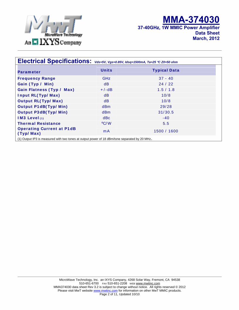
Electrical Specifications: Vds=5V, Vgs=0.85V, Idsq=1500mA, Ta=25 C Z0=50 ohm
Parameter Units Typical Data Frequency Range GHz 37 - 40 Gain (Typ / Min) dB 24 / 22 Gain Flatness (Typ / Max) +/-dB 1.5 / 1.8 Input RL(Typ/Max) dB 10/8 Output RL(Typ/Max) dB 10/8 Output P1dB(Typ/Min) dBm 29/28 Output P3dB(Typ/Min) dBm 31/30.5 IM3 Level (1) dBc -40 Thermal Resistance ⁰C/W 5.5 Operating Current at P1dB (Typ/Max) mA 1500 / 1600 (1) Output IP3 is measured with two tones at output power of 18 dBm/tone separated by 20 MHz.
MMA-374030 37-40GHz, 1W MMIC Power Amplifier
Data SheetMarch, 2012
MicroWave Technology, Inc. an IXYS Company, 4268 Solar Way, Fremont, CA 94538 510-651-6700 FAX 510-651-2208 WEB www.mwtinc.com
Applications The MMA374030 MMIC power amplifier is designed for use as a power stage amplifier in microwave transmitters. It is ideally suited for 37 to 40GHz band point to point radio applications requiring a flat gain response and excellent linearity performance. This amplifier is provided as a 5x5mm QFN package, and the packaged amplifier is fully compatible with industry standard high volume surface mount PCB assembly processes.
Biasing and Operation The recommended bias conditions for best performance for the MMA374030 are VDD = 6.0V, Idsq = 1500mA. Performance improvements are possible depending on applications. The drain bias voltage range is 4 to 6V and the quiescent drain current biasing range is 1000mA to 2000mA. A single DC gate supply connected to Vg will bias all the amplifier stages. Muting can be accomplished by setting Vg to the pinch-off voltage (Vp=-2V). The gate voltage (Vg) should be applied prior to the drain voltages (Vd1, Vd2, Vd3, Vd4) during power up and removed after the drain voltages during power down. The RF input and output ports are DC decoupled internally. Typical DC supply connection with bi-passing capacitors for the MMA374030 is shown in following pages.
Assembly Techniques GaAs MMICs are ESD sensitive. ESD preventive measures must be employed in all aspects of storage, handling, and assembly. MMIC ESD precautions, handling considerations, die attach and bonding methods are critical factors in successful GaAs MMIC performance and reliability.
MMA-374030 37-40GHz, 1W MMIC Power Amplifier
Data SheetMarch, 2012
MicroWave Technology, Inc. an IXYS Company, 4268 Solar Way, Fremont, CA 94538 510-651-6700 FAX 510-651-2208 WEB www.mwtinc.com
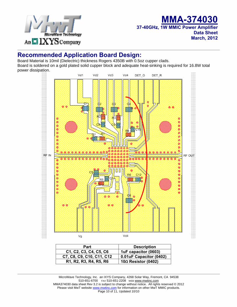
Recommended Application Board Design: Board Material is 10mil (Dielectric) thickness Rogers 4350B with 0.5oz cupper clads. Board is soldered on a gold plated solid cupper block and adequate heat-sinking is required for 16.8W total power dissipation.
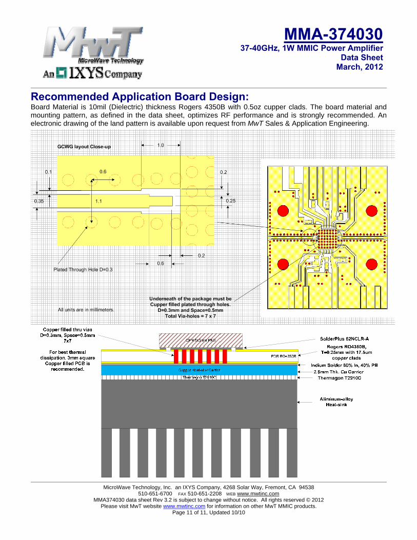
Recommended Application Board Design: Board Material is 10mil (Dielectric) thickness Rogers 4350B with 0.5oz cupper clads. The board material and mounting pattern, as defined in the data sheet, optimizes RF performance and is strongly recommended. An electronic drawing of the land pattern is available upon request from MwT Sales & Application Engineering.