42
Integration Guide MMI-20029785, Rev AA March 2016 Micro Motion ® Model 5700 Transmitters PROFINET Siemens PLC Integration Guide

Integration GuideMMI-20029785, Rev AA
March 2016
Micro Motion® Model 5700 Transmitters
PROFINET Siemens PLC Integration Guide

Emerson Flow customer service
Email:
• Worldwide: [email protected]
• Asia-Pacific: [email protected]
Telephone:
North and South America Europe and Middle East Asia Pacific
United States 800-522-6277 U.K. 0870 240 1978 Australia 800 158 727
Canada +1 303-527-5200 The Netherlands +31 (0) 704 136 666 New Zealand 099 128 804
Mexico +41 (0) 41 7686 111 France 0800 917 901 India 800 440 1468
Argentina +54 11 4837 7000 Germany 0800 182 5347 Pakistan 888 550 2682
Brazil +55 15 3413 8000 Italy 8008 77334 China +86 21 2892 9000
Venezuela +58 26 1731 3446 Central & Eastern +41 (0) 41 7686 111 Japan +81 3 5769 6803
Russia/CIS +7 495 981 9811 South Korea +82 2 3438 4600
Egypt 0800 000 0015 Singapore +65 6 777 8211
Oman 800 70101 Thailand 001 800 441 6426
Qatar 431 0044 Malaysia 800 814 008
Kuwait 663 299 01
South Africa 800 991 390
Saudi Arabia 800 844 9564
UAE 800 0444 0684
Contents
Chapter 1 Before you begin ............................................................................................................ 11.1 About this document ................................................................................................................... 11.2 Related documentation ............................................................................................................... 1
Chapter 2 Model 5700 transmitters in Ethernet networks .............................................................. 32.1 Star topology ............................................................................................................................... 32.2 Ring topology .............................................................................................................................. 42.3 Daisy-chain topology ................................................................................................................... 4
Chapter 3 Establish cyclic data ....................................................................................................... 53.1 Install the GSDXML file ................................................................................................................. 53.2 Create a PROFINET network ......................................................................................................... 63.3 Configure Ethernet IP address and device name .........................................................................123.4 Verify communications ..............................................................................................................153.5 Troubleshooting the PROFINET integration ............................................................................... 16
Chapter 4 Configuring Siemens PLC read/write operation ............................................................ 19
Appendices and referenceAppendix A Input and output slots .................................................................................................. 27
A.1 Input slots ..................................................................................................................................27A.2 Output slots ...............................................................................................................................32
Contents
PROFINET Siemens PLC Integration Guide i

Contents
ii Micro Motion® Model 5700 Ethernet transmitters

1 Before you beginTopics covered in this chapter:
• About this document
• Related documentation
1.1 About this documentThis document provides information about how to integrate a Micro Motion Model 5700Ethernet transmitter communicating with a Siemens Simatic S7-400 PLC using a SimaticManager project.
The information in this document assumes that users understand:
• Transmitter programming concepts and procedures
• All corporate, local government, and national government safety standards andrequirements that guard against data loss, equipment failure, injuries, or death
1.2 Related documentationYou can find all product documentation via the Micro Motion product documentation DVDshipped with the product or at www.micromotion.com.
Additional documentation and resourcesTable 1-1:
Topic Document
Transmitter installation Micro Motion Model 5700 Transmitters Ethernet Installation Manual
Hazardous area installation See the approval documentation shipped with the transmitter,or download the appropriate documentation from theMicro Motion web site at www.micromotion.com.
Transmitter configuration anduse
Micro Motion Model 5700 Transmitters Ethernet Configuration andUse Manual
Product Data Sheet Micro Motion Model 5700 Product Data Sheet (PDS)
Modbus configuration Modbus Interface Tool (MIT) — available at www.micromotion.com
Before you begin
PROFINET Siemens PLC Integration Guide 1

Before you begin
2 Micro Motion® Model 5700 Ethernet transmitters

2 Model 5700 transmitters in EthernetnetworksTopics covered in this chapter:
• Star topology
• Ring topology
• Daisy-chain topology
You can install the Model 5700 transmitter in star, ring, or daisy-chain networks usingindustrial-rated shielded Ethernet cables.
• Make sure that each cable is no longer than 100 meters.
• Connect the Model 5700 transmitter to the host system via a LAN (Local AreaNetwork) and not a WAN (Wide Area Network).
• Follow all network security best practices.
2.1 Star topologyModel 5700 transmitters can be installed in a star network.
Model 5700 star networkFigure 2-1:
A. Programmable Logic Controller (PLC)B. Model 5700 with Ethernet outputC. External Ethernet switch
Model 5700 transmitters in Ethernet networks
PROFINET Siemens PLC Integration Guide 3

2.2 Ring topologyModel 5700 transmitters can be installed in a ring network.
Model 5700 ring networkFigure 2-2:
A. Programmable Logic Controller (PLC)B. Model 5700 with Ethernet output
2.3 Daisy-chain topologyModel 5700 transmitters can be installed in a daisy-chain network.
Model 5700 daisy-chain networkFigure 2-3:
A. Programmable Logic Controller (PLC)B. Model 5700 with Ethernet output
Model 5700 transmitters in Ethernet networks
4 Micro Motion® Model 5700 Ethernet transmitters

3 Establish cyclic dataTopics covered in this chapter:
• Install the GSDXML file
• Create a PROFINET network
• Configure Ethernet IP address and device name
• Verify communications
• Troubleshooting the PROFINET integration
3.1 Install the GSDXML file1. Download the GSDXML file using one of the following methods:
Option Description
Use a USBmemorydrive
a. Insert a USB memory drive into the Model 5700 Ethernet service port.
The service port connection is located under the transmitter cap.
b. From the transmitter display, choose Menu > USB Options > Transmitter >USB Drive > Download Support Files > GSD file.
c. Follow the menu to copy the GSDXML file to the USB memory drive.d. Copy the zip file from the USB memory drive to the PC where SIMATIC
Manager is installed.e. Unzip the file to a chosen location.
Downloadthe file
a. Download the GSDXML file from the Micro Motion Model 5700 Ethernetproduct website.
b. Unzip the file to a chosen location.
2. To install the Model 5700 PROFINET GSDXML file into your GSD file catalog using theHW config in SIMATIC Manager:
a. Choose Options > Install GSD File.
Establish cyclic data
PROFINET Siemens PLC Integration Guide 5

Example:
b. Select Install.c. Choose Update Catalog.
3.2 Create a PROFINET network1. Configure the primary protocol as PROFINET in the Model 5700 device:
a. From the transmitter display, choose Device Tools > Configuration > Network Settings.
Establish cyclic data
6 Micro Motion® Model 5700 Ethernet transmitters

b. Select Profinet.2. From SIMATIC Manager, choose File > 'New Project' Wizard.
3. Follow the wizard to select the CPU for your PLC.
Example: CPU 400
4. In the Component View, click on the CPU.
5. Double-click Connections.
A graphical representation of the network is displayed.
6. Double-click the CPU icon.
The HW Config screen is displayed.
7. Double-click the interface, then click Properties.
Example:
The network settings of the S7 400 PLC Ethernet interface are configured.
8. Right-click on the Ethernet interface, and select Insert PROFINET IO System.
Example:
Establish cyclic data
PROFINET Siemens PLC Integration Guide 7

The Ethernet network is created.
9. Double-click on the PROFINET network you just created.
The Properties menu is displayed.
10. Enter the name of the network.
Example:
11. (Optional) To use the network name in the IO device and in the controller, check Usethe name in IO device/controller.
Establish cyclic data
8 Micro Motion® Model 5700 Ethernet transmitters

12. Drag and drop the device called Standard from the GSD file catalog to the Model5700 Ethernet network.
The Model 5700 Ethernet network is located at PROFINET IO > Additional Field Devices >Sensors > Coriolis > 5700 Coriolis Meter.
Example:
13. Double-click on the device to enter the configuration menu.
14. Enter the Device name.
NoteThe Device name must:
• Follow all DNS conventions
• Cannot start with a number
• Cannot contain uppercase alpha characters
15. Make the appropriate IP address configuration of the device, and press Ok.
You can use the Ethernet button if required.
If the Use name in IO device/controller checkbox is checked in the network properties,then Device name will have the following format: device_name.network_name.
Establish cyclic data
PROFINET Siemens PLC Integration Guide 9

Option Description
Device name when the Usename in IO device/controllercheckbox is unchecked
Device name when the Usename in IO device/controllercheckbox is checked
16. Click on the Model 5700 Ethernet icon to display the HW configuration in the lowerscreen.
17. From the HW Catalog, drag the input and output slots to one of the followinglocations:
• PROFINET IO > Additional Field Devices > Sensors > Coriolis > 5700 Coriolis Meter >Standard > Input Modules – Slot 1
• PROFINET IO > Additional Field Devices > Sensors > Coriolis > 5700 Coriolis Meter >Standard > Output Modules – Slot 2
Establish cyclic data
10 Micro Motion® Model 5700 Ethernet transmitters

Example:
If Empty is selected, delete the slot by right-clicking on the slot, and selecting Delete.
For a description of the Input and Output slots, see Appendix A.
Example: In this example, Small Configurable Data has been added to Slot 1.
18. Press Save and Compile.
19. Press Download to Module to download the configuration into the CPU module.
NoteThe modules configured and downloaded in the HW Config are set in the transmitter. You donot need to set the Input or Output modules on the transmitter first. You can configure thevariables in the input data sets using the web server or ProLink III.
Example:
Establish cyclic data
PROFINET Siemens PLC Integration Guide 11

The configuration is downloaded into the CPU module. The PLC should show a redLED bus fault.
3.3 Configure Ethernet IP address and device nameUse this procedure to configure the Ethernet IP address and device name for the Model5700 Ethernet device.
1. Choose PLC > Ethernet > Edit Ethernet Node.
Example:
2. To configure the programming machine (PG) to PC interface, choose Options > SetPG/PC Interface…
Example:
3. Press Browse to find the Model 5700 Ethernet device on the network.
TipIf you cannot find the Model 5700 device, turn off your firewall. Firewalls sometimes preventSIMATIC Manager from browsing network devices.
Example:
Establish cyclic data
12 Micro Motion® Model 5700 Ethernet transmitters

4. Select the device from the list and press Ok.
Example:
5. Fill in the appropriate network settings and press Assign IP Configuration.
6. Fill in the device name and press Assign Name.
Make sure the IP configuration and device name are the same as what youconfigured in Section 3.2.
Example:
Establish cyclic data
PROFINET Siemens PLC Integration Guide 13

7. Press Browse again to make sure the changes were applied to the device.
Example:
8. Choose PLC > Ethernet > Verify Device Name to verify the device name was properlyassigned.
Example:
Establish cyclic data
14 Micro Motion® Model 5700 Ethernet transmitters

3.4 Verify communications1. Verify that the PLC shows no faults (red lights).
The most likely error will be a Bus Fault (BF LED is red), which means either the DeviceName, the IP address, the Input Slot, or the Output Slot between the PLC and the Model5700 Ethernet transmitter does not match.
2. To verify you are receiving data:
a. In the HW Config, click the Model 5700 Ethernet icon.
b. Right-click on the Input Slot and press Monitor/Modify.
c. Click the I/O Display box and the Monitor box to see the process variables updating.
Example:
Establish cyclic data
PROFINET Siemens PLC Integration Guide 15

3. If the transmitter is still not communicating, from the transmitter display, chooseMenu > Configuration > Ethernet settings > Primary Protocol > Profinet to verify that PROFINETis the configured primary protocol on the Model 5700 Ethernet transmitter.
3.5 Troubleshooting the PROFINET integration
3.5.1 Cannot download PROFINET into the PLC controllerUse the following procedure if you cannot download the PROFINET program into the PLCcontroller.
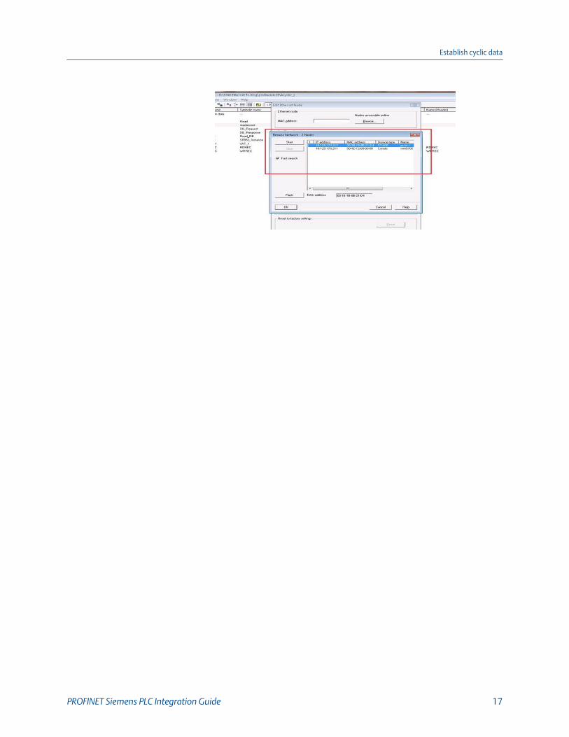
1. Choose PLC > Ethernet > Edit Ethernet Node.
2. Select Browse.
A list of network devices with MAC IDs is displayed.
3. Select the PROFINET controller and press OK.
Example:
Establish cyclic data
16 Micro Motion® Model 5700 Ethernet transmitters
Establish cyclic data
PROFINET Siemens PLC Integration Guide 17

Establish cyclic data
18 Micro Motion® Model 5700 Ethernet transmitters

4 Configuring Siemens PLC read/writeoperation
1. To insert the data blocks:
You will use the data blocks to configure the request and response parameters onthe Siemens PLC.
a. From the SIMATIC Manager screen, select Insert > S7 Block > Data Block.
Example:
b. From the Properties screen, enter the values as shown in the following exampleand select OK.
Example:
The first of two data blocks is created.
Configuring Siemens PLC read/write operation
PROFINET Siemens PLC Integration Guide 19

c. From the Properties screen, enter the values as shown in the following exampleand select OK.
The second of two data blocks is created.
2. To copy the SFB52 and SFB53 data blocks to your project:
a. From the SIMATIC Manager screen, select File > Open and select the Library tab.
b. Select Standard Library and press OK.
Example:
The pre-defined library opens.
c. From the Standard Library tree view, select System Function Blocks > Blocks.
d. From the right panel, select SFB52 and SFB53, and select Copy.
Configuring Siemens PLC read/write operation
20 Micro Motion® Model 5700 Ethernet transmitters
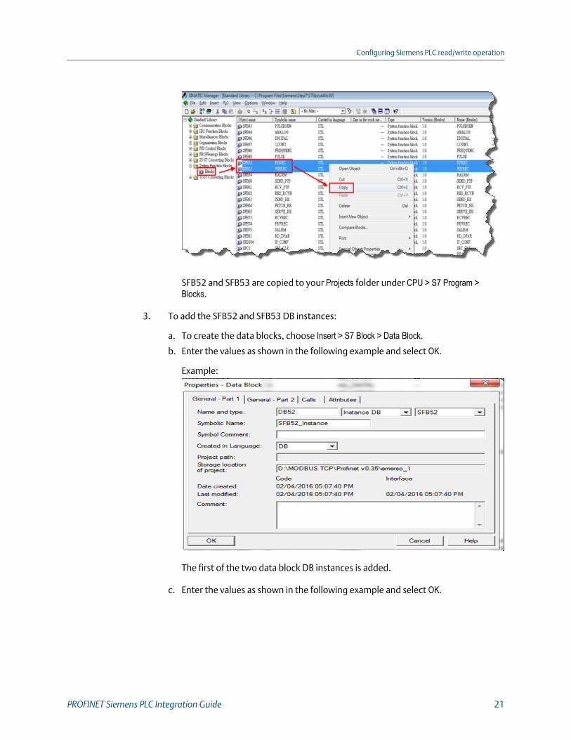
SFB52 and SFB53 are copied to your Projects folder under CPU > S7 Program >Blocks.
3. To add the SFB52 and SFB53 DB instances:
a. To create the data blocks, choose Insert > S7 Block > Data Block.
b. Enter the values as shown in the following example and select OK.
Example:
The first of the two data block DB instances is added.
c. Enter the values as shown in the following example and select OK.
Configuring Siemens PLC read/write operation
PROFINET Siemens PLC Integration Guide 21

The second of the two data block DB instances is added. The SIMATIC Managerdisplays the entries.
4. To configure the DB2 Request data block, double-click DB2 Request and enter thevalues as shown in the following example.
Example:
5. To configure the DB3 Response data block, double-click DB3 Response and enter thevalues as shown in the following example.
Example:
6. To program acyclic read:
Configuring Siemens PLC read/write operation
22 Micro Motion® Model 5700 Ethernet transmitters

a. Double-click OB1.
Example:
b. Choose Insert > Network.
Example:
c. To configure the input and output parameters, from SFB blocks, drag SFB52 toNetwork.
Example:
Configuring Siemens PLC read/write operation
PROFINET Siemens PLC Integration Guide 23

Parame-ter Description
REQ The Read request is sent to the Model 5700 using bit memory M8.2. Youhave the following options:• 1 (true) starts the read request. You must end the request.• 0 (false) ends the request. Reset Bit logic is used to reset M8.2.
VALID Bit memory M8.4 indicates whether a new data record was received andvalid.
BUSY Bit memory M8.3 indicates whether the read process has terminated ornot.
ERROR Bit memory M8.5 indicates whether an error has occurred while processingthe function.
STATUS The double-word bit memory MD18 contains an error code. For error de-scriptions, see Help on system functions / function blocks.
ID Displays the PN-IO diagnostic address (for example, “8180” = 1FF4 hex).This address is used for PROFINET acyclic read/write to the Model 5700Estation to perform pre-defined diagnoses.
INDEX Displays the data record number (247 – starting Modbus register for massflow). For the Model 5700, the starting address is 1.
MLEN The maximum length in bytes of data record information to be fetched.
RECORD The destination area for the read data record. For DB3 in this example, thestarting address is 0 and the address length is two bytes.
d. Read the acyclic parameters displayed in the Actual value field.
Example:
7. To program acyclic write, choose S7 Program > Blocks and double-click OB1.
The OB1 block is a Program Cycle Organization Block. The S7 CPU operating systemexecutes OB1 periodically. When OB1 has been executed, the operating systemrestarts it. Cyclic execution of OB1 is started after the start-up has been completed.
a. To edit the program, select OB1.
b. Choose Insert > Network.
c. From SFB blocks, drag SFB53 to Network and and configure the input and output asshown in the following example.
Example:
Configuring Siemens PLC read/write operation
24 Micro Motion® Model 5700 Ethernet transmitters

8. To create a variable table:
Use the variable table to modify and monitor the connected PLC variables andmemory content.
a. From the SIMATIC Manager screen, choose Insert > S7 Block > Variable Table.
b. Enter the values as shown in the following examples and save your changes.
Example:
The write request is sent to the Model 5700 using bit memory M1.0.
c. To start the read request, enter 1 (true) in the Modify value field, right-click, andpress Modify.
d. To end the request, enter 0 (false) in the Modify value field, right-click, and pressModify.
9. To download a project to PLC:
Configuring Siemens PLC read/write operation
PROFINET Siemens PLC Integration Guide 25

a. From the SIMATIC Manager screen, select the Download to Module icon.
The configuration is downloaded to your CPU.
b. After the project downloads, open the vat table and make the corresponding M1.0, 8.2 bits high for read and read/write.
The read request is sent to the Model 5700 using bit memory M8.2. The writerequest is sent to the Model 5700 using bit memory M1.0.
c. Go online to read and write acyclic data into the Model 5700 device module.
Configuring Siemens PLC read/write operation
26 Micro Motion® Model 5700 Ethernet transmitters

Appendix AInput and output slots
Topics covered in this appendix:
• Input slots
• Output slots
A.1 Input slotsEmpty
Use the Empty Input slot when no input data is required. Typically for a Model 5700Ethernet mass flow meter, the Empty Input slot is unused because this meter is ameasuring device.
Common input dataTable A-1:
AssemblyDword
index Name Data type
0 Mass Flow REAL
1 Temperature REAL
2 Density REAL
3 Drive Gain REAL
4 Totalizer 1 (default = Mass Total) REAL
5 Inventory 1 (default = Mass Inventory) REAL
6 Status DWORD
Severity • Bit #0 = Immediate Failure• Bit #1 = Last Measure Value
Failure• Bit #2 = Function Check• Bit #3 = Out of Specification• Bit #4 = Maintenance Re-
quired
Counter/Heartbeat (bits16-32)
The PLC will display the coun-ter/heartbeat as a signed INT,therefore the counter can benegative.
Input and output slots
PROFINET Siemens PLC Integration Guide 27

Common input data (continued)Table A-1:
AssemblyDword
index Name Data type
7 Alert detail • Bit #0 = Electronics Failure• Bit #1 = Sensor Failed• Bit #2 = Configuration Error• Bit #3 = Core Low Power• Bit #4 = Security Breach• Bit #5 = Sensor-Transmitter
DWORD
Communications error • Bit #6 = Tube Not Full• Bit #7 = Extreme Primary
Purpose Variable• Bit #8 = Reserved• Bit #9 = Flowmeter Initializ-
ing• Bit #10 = Function Check in
Progress• Bit #11 = Sensor Being Si-
mulated• Bit #12 = Output Fixed• Bit #13 = Drive Over Range• Bit #14 = Process Aberra-
tion• Bit #15 = Discrete Event X
Active• Bit #16 = Output Saturated• Bit #17 = Function Check
Failed• Bit #18 = Data Loss Possible
8 Echo Output Data Discrete Actions DWORD
Liquid volume flowTable A-2:
AssemblyDword
index Name Data type
0–8 Mass Flow See Table A-1
9 Volume Flow REAL
10 Totalizer 2 (default = Volume Total) REAL
11 Inventory 2 (default = Volume Inventory) REAL
Input and output slots
28 Micro Motion® Model 5700 Ethernet transmitters

Gas volume flowTable A-3:
AssemblyDword
index Name Data type
0–8 Mass Flow See Table A-1
9 Gas Volume Flow REAL
10 Totalizer 4 (default = Gas Volume Total) REAL
11 Inventory 4 (default = Gas Volume Inventory) REAL
API ReferralTable A-4:
AssemblyDword
index Name Data type
0–8 Mass Flow See Table A-1
9 Volume Flow REAL
10 Totalizer 2 (default = Volume Total) REAL
11 Inventory 2 (default = Volume Inventory) REAL
12 Corrected Density REAL
13 Corrected Vol Flow REAL
14 Totalizer 3 (default = Corrected Vol Total) REAL
15 Inventory 3 (default = Corrected Vol Inv) REAL
16 Avg Density REAL
17 Avg Temperature REAL
18 CTL REAL
Concentration MeasurementTable A-5:
AssemblyDword
index Name Data type
0–8 Mass Flow See Table A-1
9 Volume Flow REAL
10 Totalizer 2 (default = Volume Total) REAL
11 Inventory 2 (default = Volume Inventory) REAL
12 Density at Reference REAL
13 Std Vol Flow Rate REAL
14 Totalizer 5 (default = Std Vol Total) REAL
15 Inventory 5 (default = Std Vol Inv) REAL
Input and output slots
PROFINET Siemens PLC Integration Guide 29

Concentration Measurement (continued)Table A-5:
AssemblyDword
index Name Data type
16 Net Mass Flow Rate REAL
17 Totalizer 6 (default = Net Mass Total) REAL
18 Inventory 6 (default = Net Mass Inv) REAL
19 Net Vol Flow Rate REAL
20 Totalizer 7 (default = Net Vol Flow Total) REAL
21 Inventory 7 (default = Net Vol Flow Inv) REAL
22 Concentration REAL
23 Density - Fixed SG Units REAL
24 Density - Fixed Baume Units REAL
BatcherTable A-6:
AssemblyDword
index Name Data type
0–8 Mass Flow See Table A-2
9–11 Liquid Volume
12 Batch Total REAL
13 Overshoot Compensation Value (Reg 1457) REAL
14 Batch Fill Time REAL
15 Fill status and diagnostics
• Bit #0 - Primary Fill in progress (reg 2495 bit 0)• Bit #1 - Primary AOC training (reg 2495 bit 9)• Bit #2 = Primary Valve (reg 2495 bit 5• Bit #3 = Undefined• Bit #4 = Undefined• Bit #5 = Undefined• Bit #6 - Fill Start Not Okay (reg 2496 bit 0)• Bit #7 - AOC Flow Rate Too High (reg 2496 bit 1)• Bit #8 - Maximum Fill Time Exceeded (reg 2496 bit
2)• Bit #9 - Slug Flow (reg 2496 bit 3)• Bit #10 - Tube Not Full (reg 2496 bit 4)• Bit #11 - Drive Overrange (reg 2496 bit 5)• Bit #12 - Critical Sensor Failure (reg 2496 bit 6)• Bit #13 - Critical Transmitter Failure (reg 2496 bit 7)• Bit #14 - Density Out of Limits (reg 2496 bit 8)• Bit #15 - Temperature Out of Limits (reg 2496 bit 9)• Bit #16 - Bit #31 for future expansion
DWORD
Input and output slots
30 Micro Motion® Model 5700 Ethernet transmitters

Small input configurable data setTable A-7:
AssemblyDword
index Name Data type
0–8 Mass Flow See Table A-1
9–16 8 configurable slots REAL *8
Medium input configurable data setTable A-8:
AssemblyDword
index Name Data type
0–8 Mass Flow See Table A-1
9–24 16 configurable slots REAL *16
Large input configurable data setTable A-9:
AssemblyDword
index Name Data type
0–8 Mass Flow See Table A-1
9–40 32 configurable slots REAL *32
Advanced Phase Measurement (APM) – liquidTable A-10:
AssemblyDword
index Name Data type
0–8 Mass Flow See Table A-1
9 Volume Flow REAL
10 Totalizer 2 (default = Volume Total) REAL
11 Inventory 2 = (default = Volume Inventory) REAL
12 Gas Void Fraction REAL
13 Contract Total 1 REAL
14 Contract Total 2 REAL
15 Contract Total 3 REAL
16 Contract Total 4 REAL
17 Net Oil Flow @ Line REAL
18 Net Water Flow @ Line REAL
19 Watercut @ Line REAL
Input and output slots
PROFINET Siemens PLC Integration Guide 31
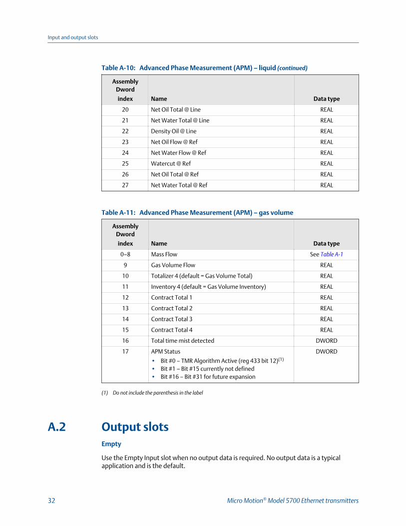
Advanced Phase Measurement (APM) – liquid (continued)Table A-10:
AssemblyDword
index Name Data type
20 Net Oil Total @ Line REAL
21 Net Water Total @ Line REAL
22 Density Oil @ Line REAL
23 Net Oil Flow @ Ref REAL
24 Net Water Flow @ Ref REAL
25 Watercut @ Ref REAL
26 Net Oil Total @ Ref REAL
27 Net Water Total @ Ref REAL
Advanced Phase Measurement (APM) – gas volumeTable A-11:
AssemblyDword
index Name Data type
0–8 Mass Flow See Table A-1
9 Gas Volume Flow REAL
10 Totalizer 4 (default = Gas Volume Total) REAL
11 Inventory 4 (default = Gas Volume Inventory) REAL
12 Contract Total 1 REAL
13 Contract Total 2 REAL
14 Contract Total 3 REAL
15 Contract Total 4 REAL
16 Total time mist detected DWORD
17 APM Status
• Bit #0 – TMR Algorithm Active (reg 433 bit 12)(1)
• Bit #1 – Bit #15 currently not defined• Bit #16 – Bit #31 for future expansion
DWORD
(1) Do not include the parenthesis in the label
A.2 Output slotsEmpty
Use the Empty Input slot when no output data is required. No output data is a typicalapplication and is the default.
Input and output slots
32 Micro Motion® Model 5700 Ethernet transmitters

Common output data — Discrete actions onlyTable A-12:
AssemblyDword
index Name Data type
0 • Bit #0 – Start Sensor Zero (trigger start with a 1, noabort)
• Bit #1 – Reset All Process Totals (same as setting bits2-8)v
• Bit #2 – Reset Totalizer 1 (Mass Total by default)• Bit #3 – Reset Totalizer 2 (Volume Total by default)• Bit #4 – Reset Totalizer 3 (PM Ref Vol Total by default)• Bit #5 – Reset Totalizer 4 (GSV Total by default)• Bit #6 – Reset Totalizer 5 (CM Ref Vol Total by default)• Bit #7 – Reset Totalizer 6 (CM Net Mass Total by default)• Bit #8 – Reset Totalizer 7 (CM Net Vol Total by default)• Bit #9 – Start All Totals (trigger start with a 1)• Bit #10 – Stop All Totals (trigger stop with a 1)
If both start and stop =1, then totals are stopped• Bit #11 – Start Smart Meter Verification (Continue Meas-
uring Mode only)
Trigger start with a 1, no abort• Bit #12 – Reset all Inventory Totals• Bit #13 – Not applicable
DWORD
External process dataTable A-13:
AssemblyDword
index Name Data type
0 Common output data (instance 150 data) See Table A-12
1 External Pressure REAL
2 External Temperature REAL
BatcherTable A-14:
AssemblyDword
index Name Data type
0 Common output data (instance 150 data) See Table A-12
1 Batch Target REAL
Input and output slots
PROFINET Siemens PLC Integration Guide 33

Batcher (continued)Table A-14:
AssemblyDword
index Name Data type
2 Batcher Control – Discrete Actions
• Bit #0 – Reserved• Bit #1 – Start Fill• Bit #2 – End Fill• Bit #2 – Pause Fill• Bit #4 – Resume Fill• Bit #5 – Reserved• Bit #6 – Start Training• Bit #7 – Save AOC Calibration• Bit #8 – Bit #31 for future expansion
DWORD
3 Maximum Batch Time (Reg 1305) REAL
Batcher and external process dataTable A-15:
AssemblyDword
index Name Data type
0–2 External process data (instance 151 data) See Table A-12
3 Batch Target REAL
4 Batcher Control – Discrete Actions
• Bit #0 – Reserved• Bit #1 – Start Fill• Bit #2 – End Fill• Bit #2 – Pause Fill• Bit #4 – Resume Fill• Bit #5 – Reserved (for Clean in Place)• Bit #6 – Start Training• Bit #7 – Save AOC Calibration• Bit #8 – Bit #31 for future expansion
DWORD
5 Maximum Batch Time (Reg 1305) REAL
Output configurable dataTable A-16:
AssemblyDword
index Name Data type
0 Common output data (instance 150 data) See Table A-12
1 Configurable Slot 1 (Register) REAL
2 Configurable Slot 2 (Register) REAL
3 Configurable Slot 3 (Register) REAL
Input and output slots
34 Micro Motion® Model 5700 Ethernet transmitters

Output configurable data (continued)Table A-16:
AssemblyDword
index Name Data type
4 Configurable Slot 4 (Register) REAL
5 Configurable Slot 5 (Register) WORD
6 Configurable Slot 6 (Register) WORD
7 Configurable Slot 7 (Register) WORD
8 Configurable Slot 8 (Register) WORD
9 Configurable Slot 9 (Coil) BOOL
10 Configurable Slot 10 (Coil) BOOL
11 Configurable Slot 11 (Coil) BOOL
12 Configurable Slot 12 (Coil) BOOL
Advanced Phase Measurement (APM)Table A-17:
AssemblyDword
index Name Data type
0 Common output data (instance 150 data) See Table A-12
1 External Pressure REAL
2 External Temperature REAL
3 External Water Cut REAL
Input and output slots
PROFINET Siemens PLC Integration Guide 35

Input and output slots
36 Micro Motion® Model 5700 Ethernet transmitters

Input and output slots
PROFINET Siemens PLC Integration Guide 37

*MMI-20029785*MMI-20029785
Rev AA
2016
Micro Motion Inc. USAWorldwide Headquarters7070 Winchester CircleBoulder, Colorado 80301T +1 303-527-5200T +1 800-522-6277F +1 303-530-8459www.micromotion.com
Micro Motion EuropeEmerson Process ManagementNeonstraat 16718 WX EdeThe NetherlandsT +31 (0) 70 413 6666F +31 (0) 318 495 556www.micromotion.nl
Micro Motion AsiaEmerson Process Management1 Pandan CrescentSingapore 128461Republic of SingaporeT +65 6777-8211F +65 6770-8003
Micro Motion United KingdomEmerson Process Management LimitedHorsfield WayBredbury Industrial EstateStockport SK6 2SU U.K.T +44 0870 240 1978F +44 0800 966 181
Micro Motion JapanEmerson Process Management1-2-5, Higashi ShinagawaShinagawa-kuTokyo 140-0002 JapanT +81 3 5769-6803F +81 3 5769-6844
©2016 Micro Motion, Inc. All rights reserved.
The Emerson logo is a trademark and service mark of EmersonElectric Co. Micro Motion, ELITE, ProLink, MVD and MVD DirectConnect marks are marks of one of the Emerson ProcessManagement family of companies. All other marks are property oftheir respective owners.


![[2010 MMI] AA. Medicare Diagnostic Testing, Anti-Markup ...archive.healthlawyers.org/google/health_law_archive/program_papers2... · -1- Medicare Diagnostic Testing, Anti-Markup Restrictions](https://static.documents.pub/doc/80x56/5ae053357f8b9afd1a8dcabf/2010-mmi-aa-medicare-diagnostic-testing-anti-markup-medicare-diagnostic.jpg)


