RED RIVER FLOODWAY EXPANSION PROJECT Railway Bridge Design – Challenges and Outcomes April 2010 COMMUNITIES TRANSPORTATION BUILDINGS INFRASTRUCTURE MMM Group Limited Prepared for: Transportation Association of Canada Submitted By:
Transcript
RED RIVER FLOODWAY EXPANSION PROJECT
Railway Bridge Design – Challenges and Outcomes
April 2010
COMMUNITIES
TRANSPORTATION
BUILDINGS
INFRASTRUCTURE
MMM Group Limited
Prepared for: Transportation Association of Canada
Submitted By:
-1-
Manitoba Red River Floodway Expansion Project Railway Bridge Design Challenges and Outcomes
Jim Lukashenko, P. Eng., MMM Group Limited Co-Author: Michael Hatch, MMM Group Limited
Paper prepared for presentation at the “Bridges – Adjusting to New Realities” Session
of the
2010 Annual Conference of the Transportation Association of Canada
Halifax, Nova Scotia
Manitoba Red River Floodway Expansion Project Railway Bridge Design Challenges and Outcomes
-2-
ABSTRACT
The existing Red River Floodway (Floodway) is a 48-kilometre long flood diversion channel that was constructed between 1962 and 1968 as a major element of a coordinated flood defense response to massive damage incurred by the City of Winnipeg during the 1950 flood. Prior to the expansion project, it protected the City up to an estimated flood magnitude that would be exceeded once in 100 years. The Government of Manitoba decided that the capacity of the Floodway should be increased to provide flood protection from an estimated flood magnitude that would be exceeded once in 700 years. They consequently embarked on a program of engineering studies and design work that included Pre-Design, Detailed Design and Contract Administration for the Red River Floodway Expansion Project. As part of the pre-design work, MMM was responsible for developing cost-optimized functional designs for retrofit or replacement of the six existing railway bridges that cross the Floodway, including related rail and road works. The large scope of work enabled the designers top utilize innovative solutions to the problems of rehabilitating the existing structures and the construction of the detour bridges. Design elements that were used on this project included:
The design of a 270 metre long reusable and moveable railway detour superstructures and piers
Precast segmental post tensioned concrete piers Shock transmission units to maximize reuse of the existing piers by redistributing the
longitudinal forces imposed by braking and traction.
Manitoba Red River Floodway Expansion Project Railway Bridge Design Challenges and Outcomes
-3-
Introduction
Engineers are faced with ever increasing challenges of optimizing designs for durability and cost while also ensuring that environmental impacts are minimized. As an industry trend, construction projects are becoming larger and more complex. Although these larger projects come with some difficulties and problems, they also afford Engineers the opportunity to think in larger terms so that economies of scale can be realized. The reconstruction of the railway bridges along the expanded Manitoba Floodway Expansion required innovative solutions to the challenges of:
1. Interacting within a large inter-company consortium towards a common goal. 2. Minimizing costs for the construction of numerous railway detours and temporary
bridges. 3. Minimizing the reconstruction costs of the existing railway bridges. 4. Minimizing the environmental impact of temporary and permanent construction
Background The existing Red River Floodway (Floodway) is a 48-kilometre long flood diversion channel that was constructed between 1962 and 1968 as a major element of a coordinated flood defense response to massive damage incurred by the City of Winnipeg during the 1950 flood. Prior to the expansion project, it protected the City up to an estimated flood magnitude that would be exceeded once in 100 years. While the successful performance of the flood control works has been demonstrated during recent extreme flood events (1970, 1974, 1979, 1987, 1996, 1997), it has been acknowledged that Winnipeg is at risk from major floods of the magnitude of the 1997 event. To address this concern, the Government of Manitoba decided that the capacity of the Floodway should be increased to provide flood protection from an estimated flood magnitude that would be exceeded once in 700 years. They consequently embarked on a program of engineering studies and design work that included Pre-Design, Detailed Design and Contract Administration for the Red River Floodway Expansion Project. As part of the pre-design work, MMM was responsible for developing cost-optimized functional designs for retrofit or replacement of the six existing railway bridges that cross the Floodway, including related rail and road works. One of the key factors specific to the railway bridges was the involvement of the four railway companies that cross the Floodway. Although the Government of Manitoba owns the bridges, they are subject to long-standing agreements that assign the railway companies certain rights regarding operations and technical approvals. Through meetings and discussions with the individual railway companies, operational and technical requirements were gathered and design options explored for incorporation into the railway bridge pre-design concepts. The two small railway operations agreed to short-term shutdown to facilitate the modification work, but this was not possible for CN and CP.
Manitoba Red River Floodway Expansion Project Railway Bridge Design Challenges and Outcomes
-4-
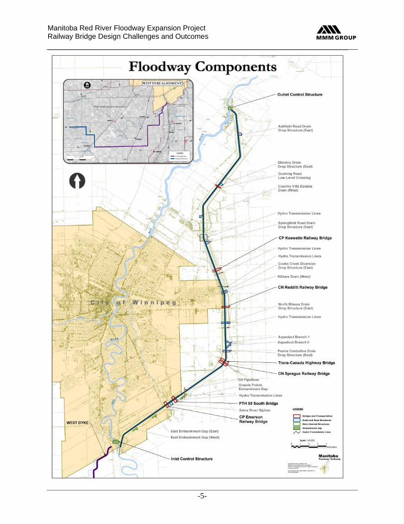
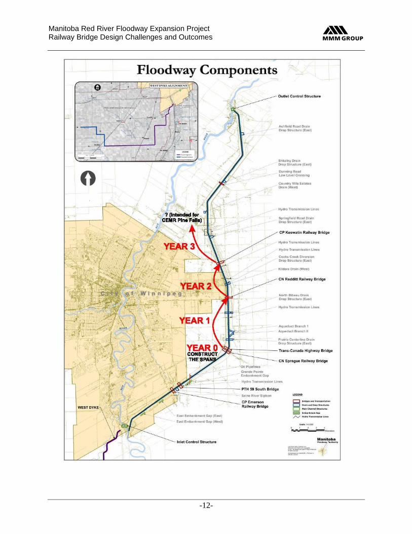
Neither CN nor CP was receptive to the idea of a permanent localized realignment of their tracks across the Floodway to enable a new bridge to be built alongside the existing one. Nor were they able to accommodate multiple stoppages to rail traffic that would be necessary for a live track girder change-out strategy for replacing the existing spans. Consequently, we developed a conceptual plan to provide a temporary detour around each of three of the main line railway crossings while the existing bridges were being modified. During the detailed design stage of the work, MMM was the Technical Lead for the railway bridge component, and was responsible for designing the first two railway bridges on the retrofit program, both of which included railway detour structures. The following graphic illustrates the magnitude of the project as well as shows the locations of the railway bridges:
Manitoba Red River Floodway Expansion Project Railway Bridge Design Challenges and Outcomes
-5-
Manitoba Red River Floodway Expansion Project Railway Bridge Design Challenges and Outcomes
-6-
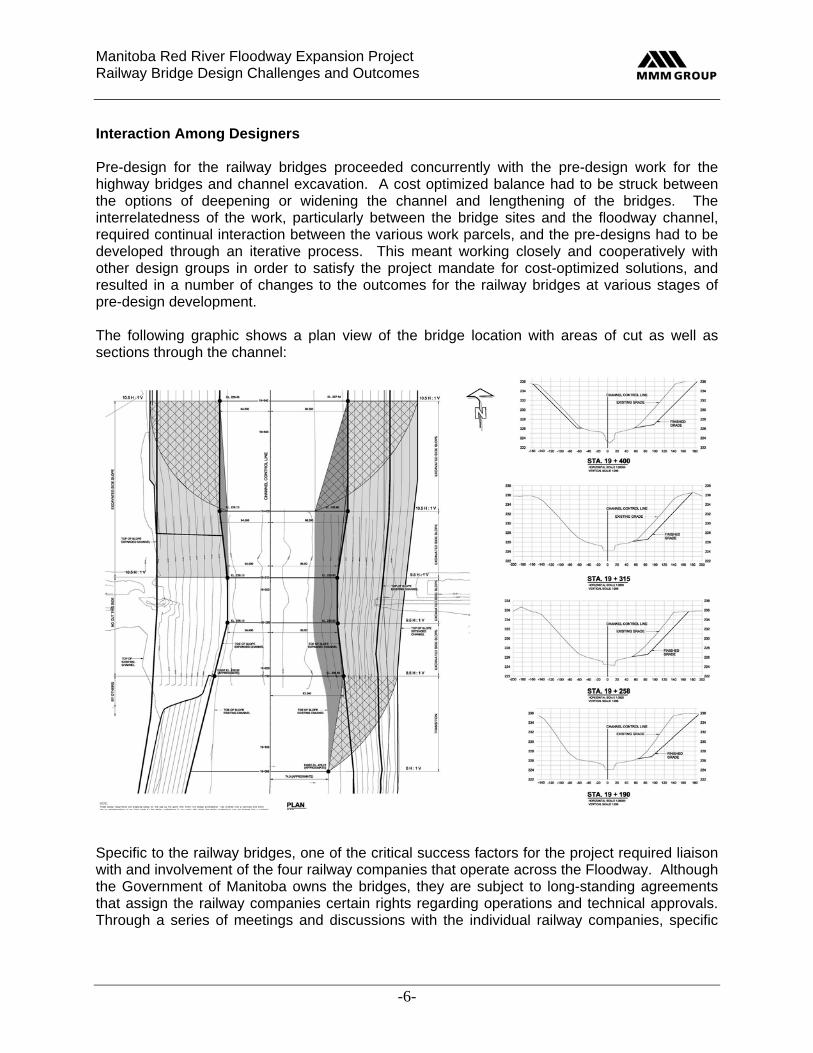
Interaction Among Designers Pre-design for the railway bridges proceeded concurrently with the pre-design work for the highway bridges and channel excavation. A cost optimized balance had to be struck between the options of deepening or widening the channel and lengthening of the bridges. The interrelatedness of the work, particularly between the bridge sites and the floodway channel, required continual interaction between the various work parcels, and the pre-designs had to be developed through an iterative process. This meant working closely and cooperatively with other design groups in order to satisfy the project mandate for cost-optimized solutions, and resulted in a number of changes to the outcomes for the railway bridges at various stages of pre-design development. The following graphic shows a plan view of the bridge location with areas of cut as well as sections through the channel:
Specific to the railway bridges, one of the critical success factors for the project required liaison with and involvement of the four railway companies that operate across the Floodway. Although the Government of Manitoba owns the bridges, they are subject to long-standing agreements that assign the railway companies certain rights regarding operations and technical approvals. Through a series of meetings and discussions with the individual railway companies, specific
Manitoba Red River Floodway Expansion Project Railway Bridge Design Challenges and Outcomes
-7-
requirements were gathered and design options explored for incorporation into the railway bridge pre-design concepts. The process was further complicated by the compressed project schedule, which meant that the impact of changes reported by other parcels at the conclusion of each iteration had to be quickly reviewed and assessed and either incorporated into the ongoing work or highlighted for immediate discussion and resolution. Working within the environment described above, a well-defined pre-design scope of work evolved for the railway bridges that captured the primary needs of the stakeholders, met the project mandate for cost-optimized solutions, met the projected overall project budget for construction, and was taken forward into final design. This was all achieved on time and on budget.
The Work Railway bridge pre-design work was primarily influenced by: External factors – these are things such as inputs from previous studies, inputs from other
PDEA2 parcels through the iterative process, and inputs from stakeholders. Previous concepts were reviewed and a scope of work developed at each bridge site based on rational engineering solutions combined with long-term cost-effectiveness. This involved intense effort and a close working relationship with the channel designer to determine an appropriate balance between widening/deepening the channel and lengthening/raising the railway bridges based on incremental cost data. Critical external factors included railway operational requirements (such as constraints on interference with train traffic), railway technical requirements (such as geometric constraints and increased loading), floodway operational requirements (such as the 1:700 year water elevation and constraints on working in the Floodway channel during April and May each year), and impacts on existing roads, overpasses, watercourses and drainage structures; and
Internal factors – these relate to the ability of the existing bridge spans, piers and
foundations to accommodate increased loading. The existing bridge spans at five of the six sites were either not strong enough to carry the required increased level of loading or had limited remaining fatigue service life. The feasibility of strengthening the existing spans using cover-plating was investigated, but this was not cost-effective. Each pier and its foundation at each bridge site were investigated to determine whether they would be adequate under increased loading and/or revised channel geometry.
Some of the external factors changed several times during the iterative process, which resulted in a relatively large number of possible courses of action for each bridge. By carefully considering existing parameters and combining them with the particular needs for each bridge, the determination of which bridges could be retrofitted and which ones should be replaced was accomplished, within the cost-optimization model. By using a standardized approach to retrofitting the bridges, the number of different types of construction activities were minimized which simplified the process of comparing costs. Once the base costs had been established for retrofitting and replacing the bridges, incremental structural costs were developed associated with lowering the channel, lengthening the bridges, and raising the bridges. These incremental costs were then used to develope a scope of work and construction strategy for each bridge, tying them in to an overall schedule to meet the planned construction completion date.
Manitoba Red River Floodway Expansion Project Railway Bridge Design Challenges and Outcomes
-8-
Although each railway bridge site is unique in its individual scope of work, a significant aspect of the pre-design involved selecting one type of superstructure for use at all sites, with the exception of the twin track site, which is a special circumstance. This enabled the use of similar details and common items of work for most of the bridges. The superstructure selected was the standard CN ballasted through plate girder, which provides the least distance from underside of girder to base-of-rail, so the amount by which the existing base-of-rail had to be raised was minimized. This led to significant savings in costs associated with adjacent existing roads, overpasses, watercourses and drainage structures compared to simply raising the existing girders. Other major items that were dealt with during pre-design included a detailed analysis of the existing piers and foundations to determine which ones could be saved and incorporated into a retrofit strategy; an acknowledgement that the main line operators cannot accommodate multiple blocks on traffic that would be necessary for a girder change-out strategy; the logistics of providing temporary detours at some of the sites; an acknowledgement that the main line operators were not prepared to accept a permanent localized realignment of their tracks across the Floodway so that a new structure could be built alongside the existing one; and the need for the short line operators to continue to transport goods during the work, albeit using an alternative method of transportation or by stockpiling goods ahead of time. Two of the more significant technical and operational drivers in determining the direction of the pre-design outcomes were: Channel geometry – namely, channel width and the 1:700 year flood water elevation, which
dictated bridge length and bridge elevation, respectively. These factors were quite volatile throughout the iterative process, which resulted in multiple revisions to the bridge modification strategies over the life of the pre-design assignment; and
Designated live loading – for the main line bridges this represented a significant increase in
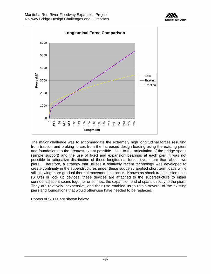
required load carrying capacity since loads were increased to Cooper E90 and Cooper E80 from original design values of Cooper E60 and Cooper E70, respectively. Live loading for the short lines remained at the original design level of Cooper E60 based on a review of the equipment currently being used and an assessment of future needs. These large increases in loading impacted on the three primary structural elements at all of the sites, namely the girders, the piers, and the foundations. Recent revisions to the railway bride design code (AREMA) resulted in higher longitudinal loads due to traction forces as opposed to braking forces on shorter spans. The figure below demonstrates the difference in design loading for traction forces and braking forces and also the previous practice of using 15% of the live load. Below is a graphical representation of the difference between traction forces and braking forces relative to the considered length:
Manitoba Red River Floodway Expansion Project Railway Bridge Design Challenges and Outcomes
-9-
Longitudinal Force Comparison
0
1000
2000
3000
4000
5000
6000
0
43
.4 59
74
.5
90
.1
10
6
12
1
13
7
15
2
16
8
18
3
19
9
21
4
23
0
24
6
26
1
27
7
29
2
Length (m)
Fo
rce
(k
N)
15%
Braking
Traction
The major challenge was to accommodate the extremely high longitudinal forces resulting from traction and braking forces from the increased design loading using the existing piers and foundations to the greatest extent possible. Due to the articulation of the bridge spans (simple support) and the use of fixed and expansion bearings at each pier, it was not possible to rationalize distribution of these longitudinal forces over more than about two piers. Therefore, a strategy that utilizes a relatively recent technology was developed to create continuity in the superstructures under these suddenly applied short term loads while still allowing more gradual thermal movements to occur. Known as shock transmission units (STU’s) or lock up devices, these devices are attached to the superstructure to either connect adjacent spans together or connect the expansion end of spans directly to the piers. They are relatively inexpensive, and their use enabled us to retain several of the existing piers and foundations that would otherwise have needed to be replaced. Photos of STU’s are shown below:
Manitoba Red River Floodway Expansion Project Railway Bridge Design Challenges and Outcomes
-10-
An analysis was performed of the entire bridge length using continuous welded rail across the bridge spans to determine the force that would be transmitted into the piers due to traction of braking. A screen shot from this analysis is shown below:
At those locations where there was still a problem, haunches were introduced on the underside of the new bridge girders at the piers to reduce the lever-arm between the underside of footing and the point of application of the horizontal force, which enabled us to retain even more of the existing piers and foundations that would otherwise have needed to be replaced.
Reusable Temporary Detour Bridge
The Detour Concept Plan The concept plan for the detours considered posted track speed, horizontal and vertical geometry, and girder selection.
Manitoba Red River Floodway Expansion Project Railway Bridge Design Challenges and Outcomes
-11-
The horizontal alignment of the permanent track at each of the three detour sites is tangent, so a temporary shoo-fly arrangement was selected to take trains around the construction. The detours were offset 20m from the live track in order to provide generous working space and reduce the amount of railway flagging protection required under strict railway safety practices. This enabled construction and demolition activities for both the detour and permanent structures to proceed with relatively few stoppages due to passing trains. Each shoo-fly is about 1.2km long, and consists of a gentle S-curve at each end that ties into the tangent track. One-degree curves were selected to avoid the need for spiral transitions and to maintain full track speed. Vertically, the detour section maintains a constant grade between the tie-in points. This geometry was accommodated within existing Floodway and railway rights-of-way, so there was no need for property purchase or short-term property rental. At this stage of the work, it was considered that the worn spans from the only existing steel through-plate girder bridge being modified might be used in the temporary detours in order to avoid the cost of renting or purchasing temporary spans that would become redundant at the end of the project. These spans would be moved down the Floodway to successive detour sites before finally being disposed of at the end of the project. The Detailed Detour Plan The challenge at the start of detailed design was to develop the pre-design detour concept plan into a comprehensive cost-optimized railway detour solution that could be applied at three sites. This was achieved through a combination of strategic thinking and the application of basic engineering principles. The first step was to develop a viable integrated schedule for carrying out the detailed design, approvals, tendering, and construction work for the six railway bridges within the stipulated time period of 3½ years. Individual schedules were developed for each site during pre-design, but these had been kept independent in order to maintain programming flexibility for as long as possible. These initial schedules were now rolled up into an integrated schedule that showed interdependencies created by the desire to use a single detour structure and move it through the project.
Manitoba Red River Floodway Expansion Project Railway Bridge Design Challenges and Outcomes
-12-
Manitoba Red River Floodway Expansion Project Railway Bridge Design Challenges and Outcomes
-13-
In developing a viable integrated schedule, consideration of the type of girders to use on the detours was made. The concept of re-using the worn spans from the only existing steel through-plate girder bridge being modified introduced a high level of risk into the construction sequencing. In addition, these spans proved to be very heavy (due to their concrete deck infill), so the idea of using them was abandoned for the detours. This released the dependency on the existing through-plate girder spans, and no longer constrained that bridge to being first on the program. Next, consideration was given to using proprietary modular steel panel spans (Acrow). However these were determined to be too expensive, and were rejected in favour of a solution that resulted in the least cost and avoided any surplus materials at the end of the project. The successful solution involved considering the entire railway bridge program as a whole, and leveraging the capital cost of the last bridge on the program by fabricating its spans first and using them in the detours at three sites before finally installing them at their designated site. This strategy was made possible by the willingness of the Manitoba Floodway Authority to adjust the cash flow model to accommodate the construction cost of the last bridge in two separate periods, namely one at the beginning of the project (fabrication of the spans) and one at the end of the project (the balance of the work). The Detour Piers Following the development of a viable integrated schedule that involved moving the detour spans through three sites, and after identifying a cost-optimized solution for the girders to be used in the detours, the next step involved strategizing a cost-optimized solution for the detour piers. Continuing the theme of moving bridge elements through the project, the idea of using modular piers that could be assembled, disassembled, and transported to the next site with relative ease was explored. In addition to their structural attributes, the piers also had to be channel friendly, that is, cause minimal interference with stream flow and minimize the potential for debris hang-up. Material selection and detailed design for the detour piers had to be carried out in a very short period of time in order to meet the project schedule for start of construction for the first railway bridge, and the pier components had to be relatively quick to fabricate. After a review of available options, it was decided to use post-tensioned modular precast concrete segments for the detour pier design. We understand from CN that this is the first time that post-tensioned modular precast concrete segments have been used for railway bridge piers in Canada, and they have expressed an interest in using this technology themselves. The Manitoba Floodway Authority accepted the risk associated with possible complications in the approvals process with the railway company in order to use this innovative approach to the pier design. Due to time constraints at the start of construction for the railway bridge modification program, the scope of work for the first railway bridge had to be split into three separate tenders. The precast concrete pier segments for the detour were tendered ahead of the detour piers and abutments, which were tendered ahead of the final package to install the detour spans and modify the permanent structure. Consequently, there were many challenges in scheduling and coordinating the work between the different contracts and
Manitoba Red River Floodway Expansion Project Railway Bridge Design Challenges and Outcomes
-14-
different contractors. The tender for fabrication of the detour spans was also put out early so that these spans would be ready at the required time. This strategy resulted in significant time savings, and enabled construction of the first railway bridge to proceed in accordance with the overall project schedule. It is unlikely that the original project schedule could have been achieved without using a modular pier design. Detour Pier Design Details Each detour pier consists of three types of pier segments, namely a base segment, as many typical segments as required for height, and a cap segment. All segment types share a common plan shape and vertical ducts to accommodate the post-tensioning bars. The plan shape consists of a pointed nose to reduce the risk of debris hang-up and minimize interference to stream flow. The width and length of the segments are driven by the geometry of the structural steel through-plate girders that sit atop the piers. Rigorous measures were built into the pier design to eliminate risk associated with such items as fit, load transfer, freezing, post-tensioning, and transportation. These measures focused on detailing of the precast concrete pier segments, and detailing of the post-tensioning system. Detailing of the precast concrete pier segments included:
Match casting to ensure full contact between adjacent segments using dry joints. Beveled steel plate shear keys cast into and projecting slightly above the top of each
segment to guide the match cast segment above into precise position (except the cap segments).
Unique raised (weld metal) identifiers on the steel shear key near the nose of each segment, consisting of the pier number and segment number, which left a mirrored imprint in the segment above for future identification and matching (except the cap segments).
An array of vertical ducts in the side walls of the segments to accommodate the post-tensioning bars.
A horizontal observation hole at each vertical duct in the bottom pier segments. Three large voids in each segment to reduce the weight so they can be transported
using non-permit trucking, lined with insulation to allow any trapped water to expand when freezing without putting pressure on the concrete (except the cap segments).
Drain holes between voids and through the side walls to equalize water pressure and reduce buoyancy (except the cap segments).
Common height established by considering the overall height requirement at each of the three sites where they will be used (except the cap segments).
Lifting holes at locations determined to provide a balanced lift during installation. A system of jacking angles and lock-off angles bolted to the outside faces near each
corner to enable precise leveling of each bottom pier segment. Pre-formed holes in the cap segments to accept the bearing anchor bolts.
Details of the post-tensioning system included:
Using temporary short extension bars set into the couplers on the anchor section of each post-tensioning bar to maintain verticality until the cast-in-place pilecap concrete had set.
Manitoba Red River Floodway Expansion Project Railway Bridge Design Challenges and Outcomes
-15-
Lining up the top of the coupler on the anchor section of each post-tensioning bar with the horizontal observation hole in the bottom pier segment to enable visual confirmation of full and proper connection of the upper section of bar.
Threading the coupler half way onto the anchor section of the post-tensioning bar and holding it in place using a plastic pipe spacer to prevent further turning onto the bar.
Painting the end of the upper section of post-tensioning bar for a distance equal to half the length of the coupler, and watching through the observation hole for the painted length to be turned fully into the coupler to ensure proper connection.
Providing specific post-tensioning bar lengths to satisfy jacking needs while avoiding conflict with the girder bottom flange at the tops of the piers.
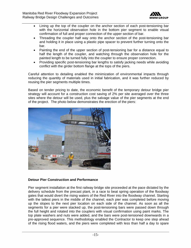
Careful attention to detailing enabled the minimization of environmental impacts through reducing the quantity of materials used in initial fabrication, and it was further reduced by reusing the pier segments multiple times. Based on tender pricing to date, the economic benefit of the temporary detour bridge pier strategy will account for a construction cost saving of 2% per site averaged over the three sites where the detour will be used, plus the salvage value of the pier segments at the end of the project. The photo below demonstrates the erection of the piers:
Detour Pier Construction and Performance Pier segment installation at the first railway bridge site proceeded at the pace dictated by the delivery schedule from the precast plant, in a race to beat spring operation of the floodway gates that would divert the rising waters of the Red River into the floodway channel. Starting with the tallest piers in the middle of the channel, each pier was completed before moving up the slopes to the next pier location on each side of the channel. As soon as all the segments for a pier were stacked up, the post-tensioning bars were passed down through the full height and rotated into the couplers with visual confirmation using paint marks. The top plate washers and nuts were added, and the bars were post-tensioned downwards in a pre-approved sequence. This methodology enabled the Contractor to keep one step ahead of the rising flood waters, and the piers were completed with less than half a day to spare
Manitoba Red River Floodway Expansion Project Railway Bridge Design Challenges and Outcomes
-16-
before their bases were inundated and access was no longer permitted under the terms of the DFO Project Authorization. The detour bridge has performing very well at all locations. Below are photos of the project demonstrating the construction:
Manitoba Red River Floodway Expansion Project Railway Bridge Design Challenges and Outcomes