CAMTECH/E/11-12/Panto AM-12/1.0 Maintenance Handbook on Pantograph AM-12 and Similar Design October, 2011 1 Hkkjr ljdkj Hkkjr ljdkj Hkkjr ljdkj Hkkjr ljdkj GOVERNMENT OF INDIA jsy ea =ky; jsy ea =ky; jsy ea =ky; jsy ea =ky; MINISTRY OF RAILWAYS egkjktiqj egkjktiqj egkjktiqj egkjktiqj, Xokfy;j & Xokfy;j & Xokfy;j & Xokfy;j & 474 005 474 005 474 005 474 005 Maharajpur, GWALIOR - 474 005 CAMTECH/ E/11-12/Panto AM-12/1.0 October, 2011 ds oy dk;Z ky;hu mi;ksx gs rq ds oy dk;Z ky;hu mi;ksx gs rq ds oy dk;Z ky;hu mi;ksx gs rq ds oy dk;Z ky;hu mi;ksx gs rq (For Official Use Only) MAINTENANCE AINTENANCE AINTENANCE AINTENANCE HANDBOOK ANDBOOK ANDBOOK ANDBOOK ON PANTOGRAPH PANTOGRAPH PANTOGRAPH PANTOGRAPH AM AM AM AM-12 12 12 12 & SIMILAR SIMILAR SIMILAR SIMILAR DESIGN DESIGN DESIGN DESIGN (WITH SPECIAL FEATURES ON PANTO ENTANGLEMENT)
Transcript
CAMTECH/E/11-12/Panto AM-12/1.0
Maintenance Handbook on Pantograph AM-12 and Similar Design October, 2011
1
Hkkjr ljdkjHkkjr ljdkjHkkjr ljdkjHkkjr ljdkj GOVERNMENT OF INDIA
jsy ea=ky;jsy ea=ky;jsy ea=ky;jsy ea=ky; MINISTRY OF RAILWAYS
October, 2011 Maintenance Handbook on Pantograph AM-12 and Similar Design
2
MAINTENANCE HANDBOOK
ON
PANTOGRAPH AM-12 & SIMILATR DESIGN
(WITH SPECIAL FEATURE ON PANTO ENTANGLEMENT)
QUALITY POLICY
“To develop safe, modern and cost
effective Railway Technology complying
with Statutory and Regulatory
requirements, through excellence in
Research, Designs and Standards and
Continual improvements in Quality
Management System to cater to
growing demand of passenger and
freight traffic on the railways”.
CAMTECH/E/11-12/Panto AM-12/1.0
Maintenance Handbook on Pantograph AM-12 and Similar Design October, 2011
3
PREFACE
The pantograph is the link between the overhead contact wire and the power circuit of the electric locomotive through which the required power is transmitted. It is essential to carry out proper maintenance of this equipment to improve the reliability of the pantograph, life of the OHE contact wire and to eliminate cases of panto entanglements.
CAMTECH has prepared this maintenance handbook on pantograph type AM 12 & similar design with the objective to disseminate knowledge of correct maintenance practices and tests as recommended by RDSO time to time among the maintenance personnel.
This handbook includes brief description of pantograph assemblies, operation, maintenance schedules, checks & testing procedures, reliability improvement measures etc. This handbook also includes special feature on panto entanglement along with check sheets and proforma.
It is clarified that this handbook does not supersede any existing provisions laid
down by RDSO or Railway Board/ Zonal Railways. The handbook is for guidance only and it is not a statutory document.
I am sincerely thankful to all field personnel who helped us in preparing this
handbook.
Technological upgradation and learning is a continuous process. Hence feel free to write us for any addition/ modification in this handbook. We shall highly appreciate your contribution in this direction.
CAMTECH, Gwalior Peeyoosh Gupta Date: 21.10.2011 Jt. Director Electrical
CAMTECH/E/11-12/Panto AM-12/1.0
October, 2011 Maintenance Handbook on Pantograph AM-12 and Similar Design
4
CONTENTS Chapter Description Pag e No.
Preface iii
Contents iv
Correction Slip vi
1 GENERAL DESCRIPTION 01
1.1 INTRODUCTION 01 1.2 TECHNICAL DETAILS 02 1.3 CONSTRUCTION OF PANTOGRAPH AM-12 03
Maintenance Handbook on Pantograph AM-12 and Similar Design October, 2011
5
Chapter Description Pag e No.
2.3 AOH/ IOH/ POH KIT for AM 12/ IR 01 & PAN 01 Pantographs (Ref : RDSO/ TC/ 0094 Rev.0 June 2007) 20
3. RELIABILITY IMPROVEMENT MEASURES 25
3.1 COMMON PANTOGRAPH DEFECTS 25
3.2 RECOMMENDATIONS 26
3.3 IMPORTANT SMIs, MODIFICATION SHEETS AND TCs FOR PANTOGRAPH AM-12 & SIMILAR DESIGN 28
4. PANTO ENTANGLEMENT 29
4.1 REASONS OF ENTANGLEMENT 29
4.1.1 OHE Defects 29
4.1.2 Pantograph defects 30
4.1.3 External Defects 31
4.2 INVESTIGATION AFTER ENTANGLEMENT 31
4.3 PREPARATION OF JOINT NOTE 32
4.3.1 OHE Defects 32
4.3.2 Defects of Pantograph 33
4.4 CHECKS AFTER PANTOGRAPH ENTANGLEMENT 34
PROFORMA ‘I’ 35
PROFORMA ‘II’ 36
ANNEXURE – I 37
REFERENCE 40
CAMTECH/E/11-12/Panto AM-12/1.0
October, 2011 Maintenance Handbook on Pantograph AM-12 and Similar Design
6
ISSUE OF CORRECTION SLIPS
The correction slips to be issued in future for this handbook will be numbered as follows : CAMTECH/E/11-12/Panto AM-12/C.S. # XX date--------- Where “XX” is the serial number of the concerned correction slip (starting from 01 onwards).
CORRECTION SLIPS ISSUED
Sr. No. Date of issue Page no. and Item no. modified
Remarks
CAMTECH/E/11-12/Panto AM-12/1.0
Maintenance Handbook on Pantograph AM-12 and Similar Design October, 2011
1
CHAPTER 1
GENERAL DESCRIPTION
1.1 INTRODUCTION
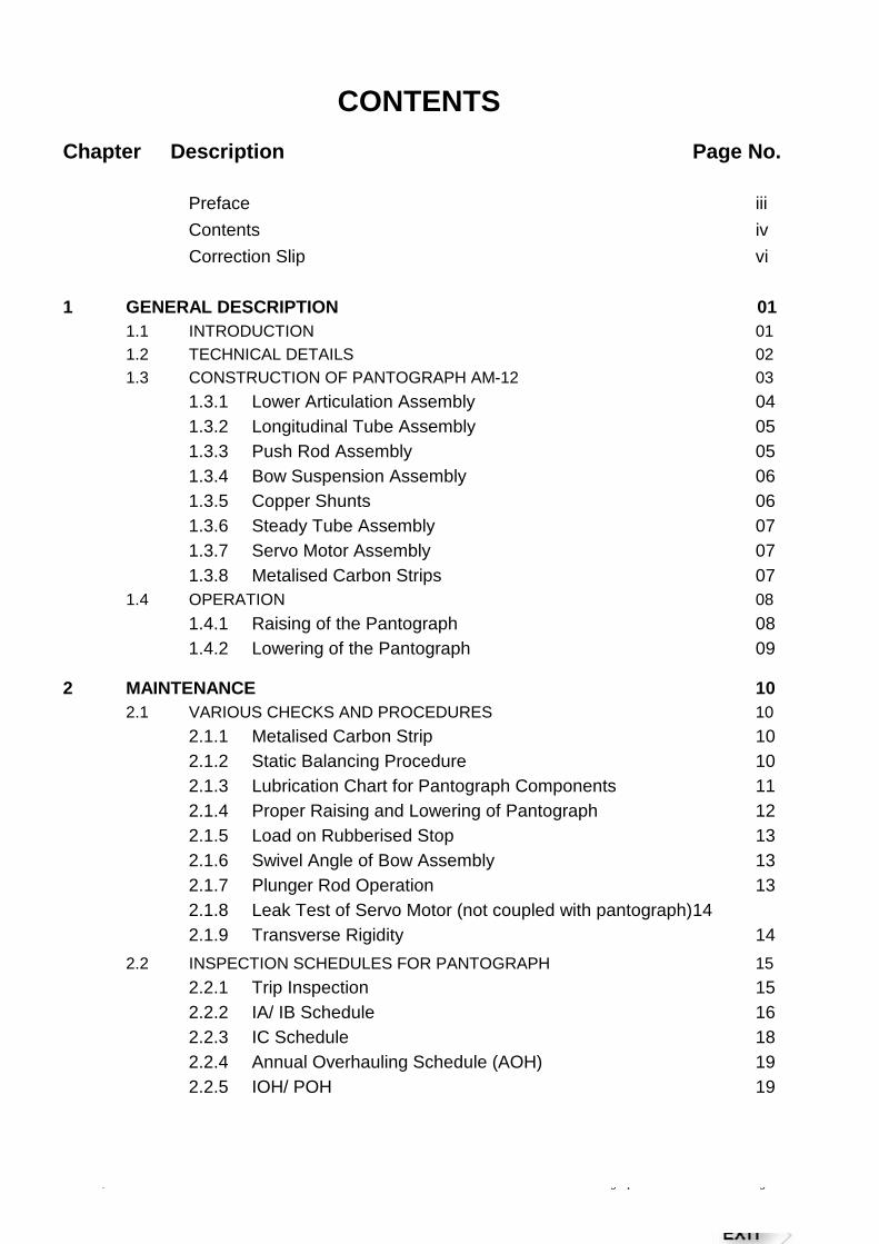
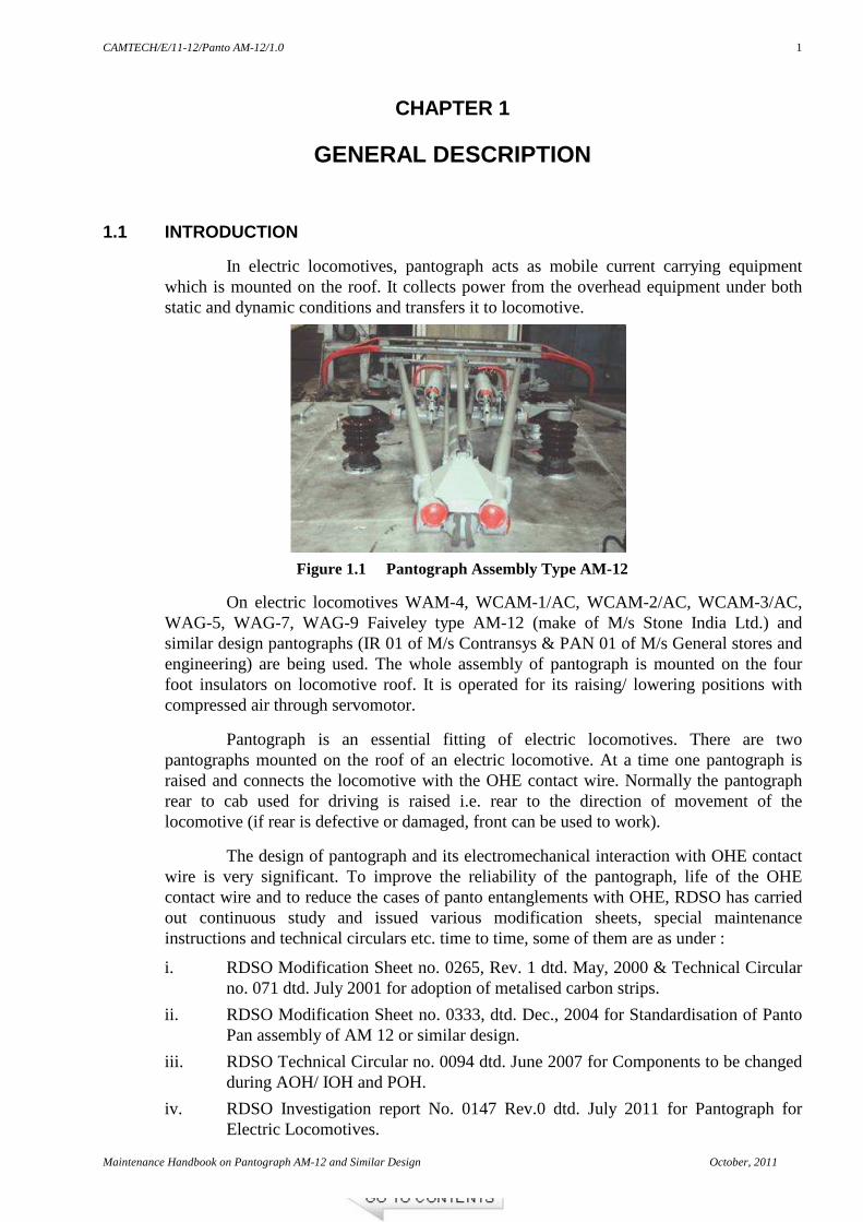
In electric locomotives, pantograph acts as mobile current carrying equipment which is mounted on the roof. It collects power from the overhead equipment under both static and dynamic conditions and transfers it to locomotive.
On electric locomotives WAM-4, WCAM-1/AC, WCAM-2/AC, WCAM-3/AC, WAG-5, WAG-7, WAG-9 Faiveley type AM-12 (make of M/s Stone India Ltd.) and similar design pantographs (IR 01 of M/s Contransys & PAN 01 of M/s General stores and engineering) are being used. The whole assembly of pantograph is mounted on the four foot insulators on locomotive roof. It is operated for its raising/ lowering positions with compressed air through servomotor.
Pantograph is an essential fitting of electric locomotives. There are two pantographs mounted on the roof of an electric locomotive. At a time one pantograph is raised and connects the locomotive with the OHE contact wire. Normally the pantograph rear to cab used for driving is raised i.e. rear to the direction of movement of the locomotive (if rear is defective or damaged, front can be used to work).
The design of pantograph and its electromechanical interaction with OHE contact wire is very significant. To improve the reliability of the pantograph, life of the OHE contact wire and to reduce the cases of panto entanglements with OHE, RDSO has carried out continuous study and issued various modification sheets, special maintenance instructions and technical circulars etc. time to time, some of them are as under :
i. RDSO Modification Sheet no. 0265, Rev. 1 dtd. May, 2000 & Technical Circular no. 071 dtd. July 2001 for adoption of metalised carbon strips.
ii. RDSO Modification Sheet no. 0333, dtd. Dec., 2004 for Standardisation of Panto Pan assembly of AM 12 or similar design.
iii. RDSO Technical Circular no. 0094 dtd. June 2007 for Components to be changed during AOH/ IOH and POH.
iv. RDSO Investigation report No. 0147 Rev.0 dtd. July 2011 for Pantograph for Electric Locomotives.
Figure 1.1 Pantograph Assembly Type AM-12
CAMTECH/E/11-12/Panto AM-12/1.0
October, 2011 Maintenance Handbook on Pantograph AM-12 and Similar Design
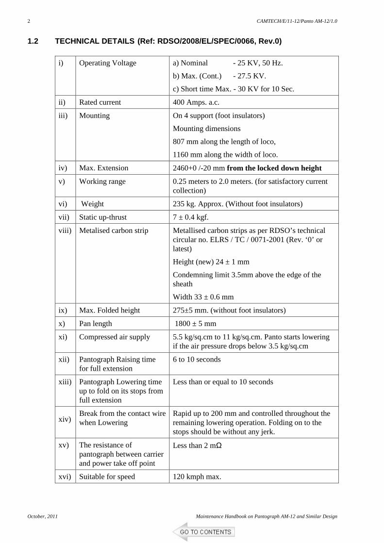
iv) Max. Extension 2460+0 /-20 mm from the locked down height
v) Working range 0.25 meters to 2.0 meters. (for satisfactory current collection)
vi) Weight 235 kg. Approx. (Without foot insulators)
vii) Static up-thrust 7 ± 0.4 kgf.
viii) Metalised carbon strip Metallised carbon strips as per RDSO’s technical circular no. ELRS / TC / 0071-2001 (Rev. ‘0’ or latest)
Height (new) 24 ± 1 mm
Condemning limit 3.5mm above the edge of the sheath
Width 33 ± 0.6 mm
ix) Max. Folded height 275±5 mm. (without foot insulators)
x) Pan length 1800 ± 5 mm
xi) Compressed air supply 5.5 kg/sq.cm to 11 kg/sq.cm. Panto starts lowering if the air pressure drops below 3.5 kg/sq.cm
xii) Pantograph Raising time for full extension
6 to 10 seconds
xiii) Pantograph Lowering time up to fold on its stops from full extension
Less than or equal to 10 seconds
xiv) Break from the contact wire when Lowering
Rapid up to 200 mm and controlled throughout the remaining lowering operation. Folding on to the stops should be without any jerk.
xv) The resistance of pantograph between carrier and power take off point
Less than 2 mΩ
xvi) Suitable for speed 120 kmph max.
CAMTECH/E/11-12/Panto AM-12/1.0
Maintenance Handbook on Pantograph AM-12 and Similar Design October, 2011
3
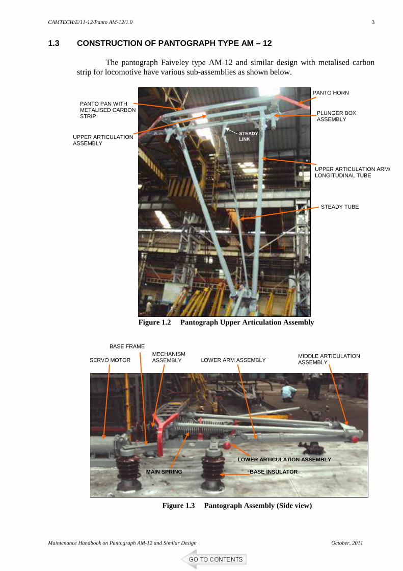
1.3 CONSTRUCTION OF PANTOGRAPH TYPE AM – 12
The pantograph Faiveley type AM-12 and similar design with metalised carbon strip for locomotive have various sub-assemblies as shown below.
PANTO HORN
PANTO PAN WITH METALISED CARBON STRIP
UPPER ARTICULATION ASSEMBLY
UPPER ARTICULATION ARM/ LONGITUDINAL TUBE
STEADY TUBE
PLUNGER BOX ASSEMBLY
STEADY LINK
MIDDLE ARTICULATION ASSEMBLY LOWER ARM ASSEMBLY
MECHANISM ASSEMBLY
BASE FRAME
BASE INSULATOR MAIN SPRING
LOWER ARTICULATION ASSEMBLY
SERVO MOTOR
Figure 1.2 Pantograph Upper Articulation Assembly
Figure 1.3 Pantograph Assembly (Side view)
CAMTECH/E/11-12/Panto AM-12/1.0
October, 2011 Maintenance Handbook on Pantograph AM-12 and Similar Design
4
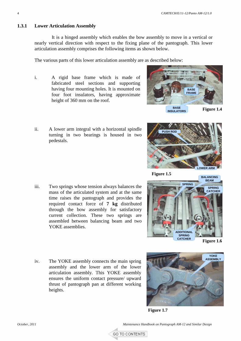
1.3.1 Lower Articulation Assembly
It is a hinged assembly which enables the bow assembly to move in a vertical or nearly vertical direction with respect to the fixing plane of the pantograph. This lower articulation assembly comprises the following items as shown below.
The various parts of this lower articulation assembly are as described below:
i. A rigid base frame which is made of
fabricated steel sections and supporting having four mounting holes. It is mounted on four foot insulators, having approximate height of 360 mm on the roof.
ii. A lower arm integral with a horizontal spindle
turning in two bearings is housed in two pedestals.
iii. Two springs whose tension always balances the
mass of the articulated system and at the same time raises the pantograph and provides the required contact force of 7 kg distributed through the bow assembly for satisfactory current collection. These two springs are assembled between balancing beam and two YOKE assemblies.
iv. The YOKE assembly connects the main spring
assembly and the lower arm of the lower articulation assembly. This YOKE assembly ensures the uniform contact pressure/ upward thrust of pantograph pan at different working heights.
BASE FRAME
BASE INSULATORS
LOWER ARM
PUSH ROD
SPRING
BALANCING BEAM
ADDITIONAL SPRING
CATCHER
YOKE ASSEMBLY
SPRING CATCHER
Figure 1.4
Figure 1.5
Figure 1.6
Figure 1.7
CAMTECH/E/11-12/Panto AM-12/1.0
Maintenance Handbook on Pantograph AM-12 and Similar Design October, 2011
5
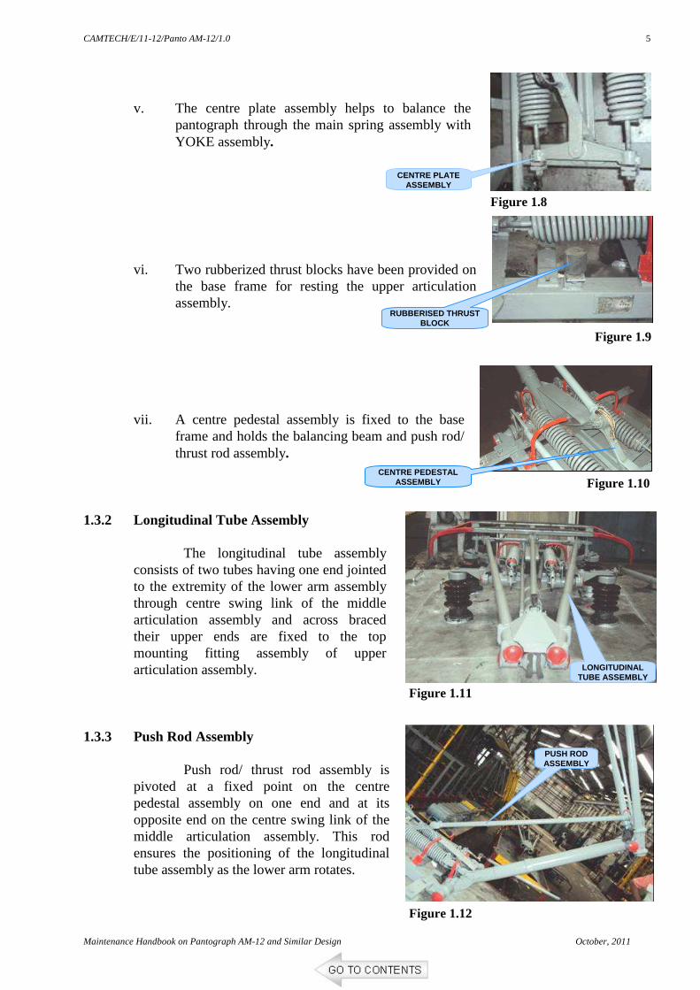
v. The centre plate assembly helps to balance the
pantograph through the main spring assembly with YOKE assembly.
vi. Two rubberized thrust blocks have been provided on
the base frame for resting the upper articulation assembly.
vii. A centre pedestal assembly is fixed to the base
frame and holds the balancing beam and push rod/ thrust rod assembly.
1.3.2 Longitudinal Tube Assembly
The longitudinal tube assembly consists of two tubes having one end jointed to the extremity of the lower arm assembly through centre swing link of the middle articulation assembly and across braced their upper ends are fixed to the top mounting fitting assembly of upper articulation assembly.
1.3.3 Push Rod Assembly
Push rod/ thrust rod assembly is pivoted at a fixed point on the centre pedestal assembly on one end and at its opposite end on the centre swing link of the middle articulation assembly. This rod ensures the positioning of the longitudinal tube assembly as the lower arm rotates.
RUBBERISED THRUST BLOCK
CENTRE PLATE ASSEMBLY
LONGITUDINAL TUBE ASSEMBLY
CENTRE PEDESTAL ASSEMBLY
PUSH ROD ASSEMBLY
Figure 1.8
Figure 1.9
Figure 1.10
Figure 1.12
Figure 1.11
CAMTECH/E/11-12/Panto AM-12/1.0
October, 2011 Maintenance Handbook on Pantograph AM-12 and Similar Design
6
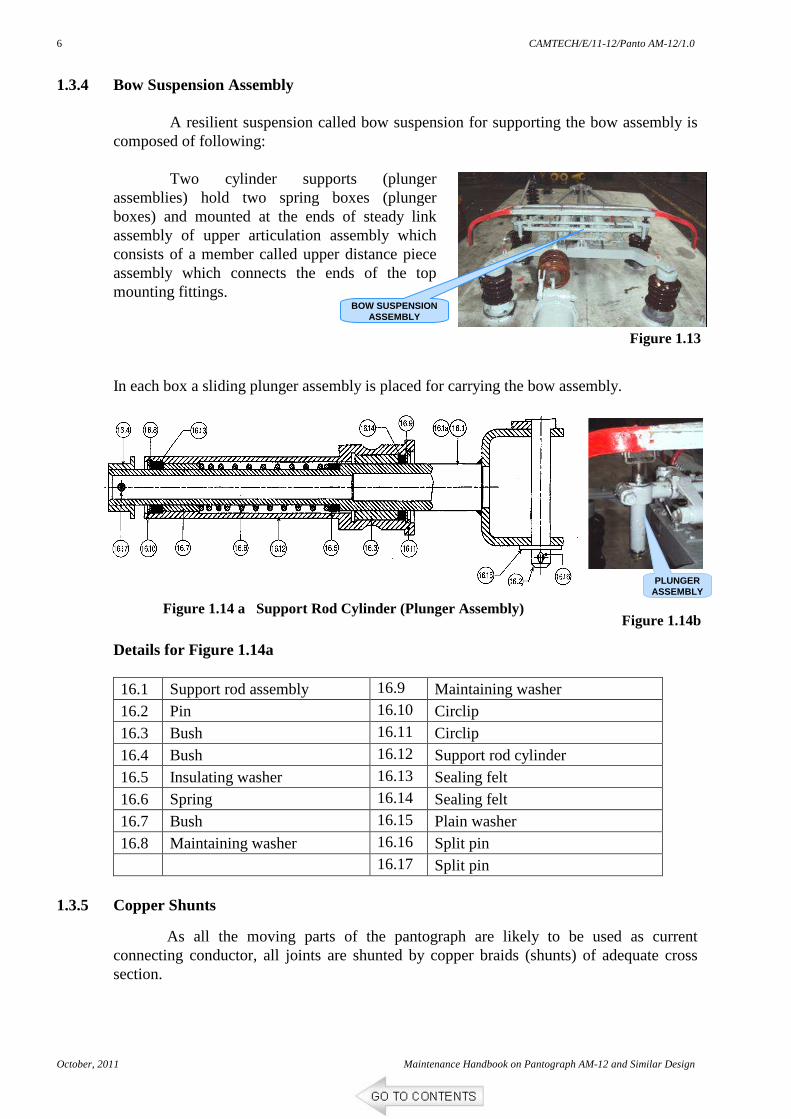
1.3.4 Bow Suspension Assembly A resilient suspension called bow suspension for supporting the bow assembly is
composed of following:
Two cylinder supports (plunger assemblies) hold two spring boxes (plunger boxes) and mounted at the ends of steady link assembly of upper articulation assembly which consists of a member called upper distance piece assembly which connects the ends of the top mounting fittings.
In each box a sliding plunger assembly is placed for carrying the bow assembly.
Details for Figure 1.14a
16.1 Support rod assembly 16.9 Maintaining washer 16.2 Pin 16.10 Circlip 16.3 Bush 16.11 Circlip 16.4 Bush 16.12 Support rod cylinder 16.5 Insulating washer 16.13 Sealing felt 16.6 Spring 16.14 Sealing felt 16.7 Bush 16.15 Plain washer 16.8 Maintaining washer 16.16 Split pin 16.17 Split pin
1.3.5 Copper Shunts
As all the moving parts of the pantograph are likely to be used as current connecting conductor, all joints are shunted by copper braids (shunts) of adequate cross section.
BOW SUSPENSION
ASSEMBLY
PLUNGER
ASSEMBLY
Figure 1.13
Figure 1.14 a Support Rod Cylinder (Plunger Assembly) Figure 1.14b
CAMTECH/E/11-12/Panto AM-12/1.0
Maintenance Handbook on Pantograph AM-12 and Similar Design October, 2011
7
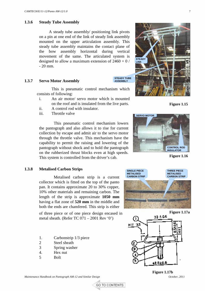
1.3.6 Steady Tube Assembly
A steady tube assembly/ positioning link pivots on a pin at one end of the link of steady link assembly mounted on the upper articulation assembly. This steady tube assembly maintains the contact plane of the bow assembly horizontal during vertical movement of the same. The articulated system is designed to allow a maximum extension of 2460 + 0 / - 20 mm.
1.3.7 Servo Motor Assembly
This is pneumatic control mechanism which consists of following: i. An air motor/ servo motor which is mounted
on the roof and is insulated from the live parts. ii. A control rod with insulator. iii. Throttle valve
This pneumatic control mechanism lowers
the pantograph and also allows it to rise for current collection by escape and admit air to the servo motor through the throttle valve. This mechanism have the capability to permit the raising and lowering of the pantograph without shock and to hold the pantograph on the rubberized thrust blocks even at high speeds. This system is controlled from the driver’s cab.
1.3.8 Metalised Carbon Strips
Metalised carbon strip is a current collector which is fitted on the top of the panto pan. It contains approximate 20 to 30% copper, 10% other materials and remaining carbon. The length of the strip is approximate 1050 mm having a flat zone of 520 mm in the middle and both the ends are chamfered. This strip is either
of three piece or of one piece design encased in metal sheath. (Refer TC 071 – 2001 Rev ‘0’)
1. Carbonstrip 1/3 piece
2 Steel sheath 3 Spring washer 4. Hex nut 5 Bolt
STEADY LINK
STEADY TUBE ASSEMBLY
SERVO MOTOR
CONTROL ROD INSULATOR
SINGLE PIECE METALISED CARBON STRIP
THREE PIECE METALISED CARBON STRIP
Figure 1.15
Figure 1.16
Figure 1.17a
Figure 1.17b
CAMTECH/E/11-12/Panto AM-12/1.0
October, 2011 Maintenance Handbook on Pantograph AM-12 and Similar Design
8
1.4 OPERATION
Basically, admission of compressed air in the pantograph servomotor raises the pantograph and the holding down springs of the servo motor lower the same. The sole function of air is to cancel the lowering effort of the spring and it has no direct effect on the pantograph. When the pantograph is working/ raised and the normal working air pressure is maintained in the servo motor, the position is kept still with the articulated system kept raised only by the up-spring device and is entirely free.
It therefore follows freely all the oscillations of the contact wire. If lack of air occurs, the equipment collapses by itself.
The whole equipment is electrically alive except pneumatic control system, its own parts are used as conductors. The current collection is made on the base frame with shunts fitted at moving points. To make feeding of compressed air easier, the control cylinder/servomotor is earthed.
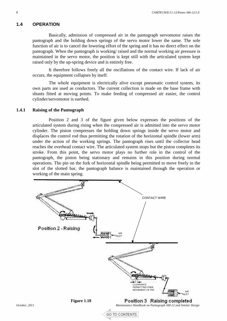
1.4.1 Raising of the Pantograph
Position 2 and 3 of the figure given below expresses the positions of the articulated system during rising when the compressed air is admitted into the servo motor cylinder. The piston compresses the holding down springs inside the servo motor and displaces the control rod thus permitting the rotation of the horizontal spindle (lower arm) under the action of the working springs. The pantograph rises until the collector head reaches the overhead contact wire. The articulated system stops but the piston completes its stroke. From this point, the servo motor plays no further role in the control of the pantograph, the piston being stationary and remains in this position during normal operations. The pin on the fork of horizontal spindle being permitted to move freely in the slot of the slotted bar, the pantograph balance is maintained through the operation or working of the main spring.
Figure 1.18
CLEARANCE PERMITTING FREE MOVEMENT OF PIN
AIR INLET
AIR INLET
CONTACT WIRE
CAMTECH/E/11-12/Panto AM-12/1.0
Maintenance Handbook on Pantograph AM-12 and Similar Design October, 2011
9
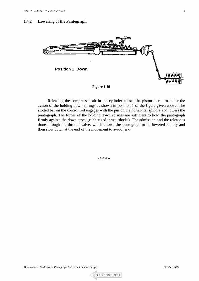
1.4.2 Lowering of the Pantograph
Releasing the compressed air in the cylinder causes the piston to return under the
action of the holding down springs as shown in position 1 of the figure given above. The slotted bar on the control rod engages with the pin on the horizontal spindle and lowers the pantograph. The forces of the holding down springs are sufficient to hold the pantograph firmly against the down stock (rubberized thrust blocks). The admission and the release is done through the throttle valve, which allows the pantograph to be lowered rapidly and then slow down at the end of the movement to avoid jerk.
********
Figure 1.19
Position 1 Down
CAMTECH/E/11-12/Panto AM-12/1.0
October, 2011 Maintenance Handbook on Pantograph AM-12 and Similar Design
10
CHAPTER 2
MAINTENANCE
2.1 VARIOUS CHECKS AND PROCEDURES
2.1.1 Metalised Carbon Strip (As per TC 071 Rev.’0’-2001, & MS/0265 Rev.1/2000) Fill up the gaps between ends of carbon strips and end wearing strip, with suitable
sealing material (M-seal etc.), in case of three piece design, fill the gaps between the carbon strips with suitable adhesive to avoid corrosion of the metal sheath and ingress of water between carbon and sheath.
Check the smoothness of the current collector surface and swiveling angle. It should be 7° ± 1° on both sides.
Measure the thickness of carbon strip above sheath. The condemning limit is 3.5 mm above the edge of the sheath. However, in schedule inspection, if the height of the carbon above the sheath is found in between 3.7 to 4.4 mm the strip may be allowed for another 10,000 km run before replacement.
If carbon strip is required to be replaced, fix it on the panto pan with a torque value of 2.5 kg-m.
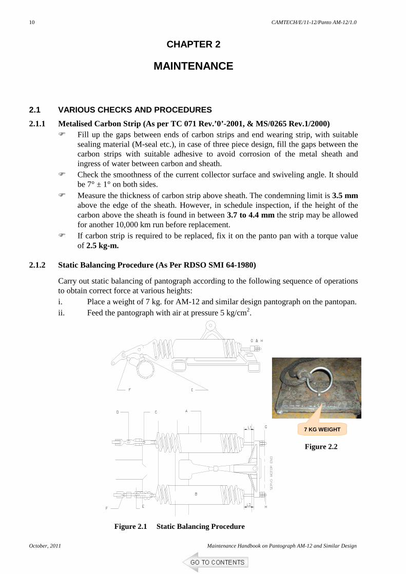
2.1.2 Static Balancing Procedure (As Per RDSO SMI 64-1980)
Carry out static balancing of pantograph according to the following sequence of operations to obtain correct force at various heights: i. Place a weight of 7 kg. for AM-12 and similar design pantograph on the pantopan. ii. Feed the pantograph with air at pressure 5 kg/cm2.
7 KG WEIGHT
Figure 2.1 Static Balancing Procedure
Figure 2.2
CAMTECH/E/11-12/Panto AM-12/1.0
Maintenance Handbook on Pantograph AM-12 and Similar Design October, 2011
11
iii. Loosen lock nuts on the regulating screws C, D, E and F.
iv. Screw down all the four regulating screws C.D.E and F.
v. Balance the pantograph at a height of 2.0 metres by tensioning the main springs A and B with the help of adjusting nuts G and H.
vi. Balance the pantograph at a height of 1.75 meters by using regulating screw F (top screw on left hand side viewing the pantograph from servo motor end).
vii. Balance the pantograph at a height of 1.5 metres by using regulating screw D (top screw on right-hand side).
viii. Balance the pantograph at a height of 1.0 metres by using regulating screw C (bottom screw on right-hand side).
ix. Balance the pantograph at a height of 0.5 metres by using regulating screw E (bottom screw on left-hand side).
x. Re-check the balancing of pantograph at heights of 2.0, 1.75, 1.5, 1.0 and 0.5 meters.
xi. Lock regulating screws with the help of Lock nuts after obtaining the balance. 2.1.3 Lubrication Chart for Pantograph Components (As per RDSO/SMI/198-1998)
Ensure proper lubrication of the components of the pantograph as per the details given below. This will help in reducing the cracks/ breakage of moving components & will also minimize the cases of panto OHE entanglement.
SL No.
Parts to be lubricated
Recommended Lubricants
Substitute Lubricant Frequency of
lubrication
1. Ball bearings
2. Servometor Piston packing
3. Articulation of thrust rod
Alvania-3 Grease (Shell)
1. Mobilux-2, Indake - GP5(IOC)
2. Multipurpose Grease-3
3. Regal Starfak Special (Shell)
4. Beacon-2 (ESSO)
AOH, IOH, POH
4. Articulation pin joints
Thuban K(Caltex)
1. Mobilux (C140)
2. Mobilux (C 90) (IOC)
3. Mobil DTEHH
4. Nassa (79)
5. Limia (15) (SHELL)
6. Thuban 140 (Caltex)
IC, AOH, IOH,POH
5. Plungers Ursa Oil (Caltex)
1. Mobil oil DTE-3, DTE-4, DTE-4D, DTE Heavy, DTE extra heavy (IOC)
2. Talpa 40 (Shell)
IB, IC, AOH, IOH,
6. Throttle valve Vaseline -- IC, AOH, IOH
CAMTECH/E/11-12/Panto AM-12/1.0
October, 2011 Maintenance Handbook on Pantograph AM-12 and Similar Design
12
2.1.4 Proper Raising and Lowering of Pantograph (As Per RDSO SMI 75-1980)
The instructions given below should be followed to ensure proper raising or lowering of pantograph:
1. Check and record the raising and lowering time of pantograph. The raising time should be 6 to 10 seconds at an air pressure of 5 kg/cm2. The lowering time should be upto 10 Seconds at an air pressure of 5 kg/cm2.
2. In case the raising time is less than the above value, balance the pantograph in accordance with para 2.1.2 as given above.(SMI 64)
3. In case raising time is more, follow the instructions contained below:-
(i) Balance the pantograph in accordance with para 2.1.2 as given above. (SMI 64)
(ii) Check and attend to any air leakage in the pneumatic circuit.
(iii) Check and attend air filter in accordance with instructions.
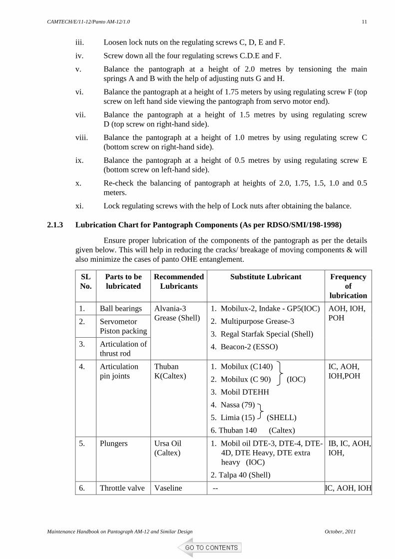
(iv) Check for air leakage at sealing joint (5) with valve seat (8). In case of air leakage replace (5) with a new one.
(v) Check for air leakage at air motor piston ring of pantograph. In case of air leakage replace the piston ring.
4. Check the lowering of Pantograph. Adjust the damping through adjusting screw (1). This screw should be so adjusted that the motion of the pan during the last phase of lowering (0.5 m) effective damping is done. At the time of touching the rubber stops the pan should rest with no jerk and without bouncing up.
5. After adjusting the damping lock the screw (1) with split pin (12). Do not disturb this adjustment for changing raising or lowering time. Readjust this screw in case the pan is found to drop with jerk or bounces up after lowering.
Maintenance Handbook on Pantograph AM-12 and Similar Design October, 2011
13
2.1.5 Load on Rubberised Stop (As per SIL Manual)
• The load of the pantograph on the rubber stop is the force required to lift the pan/ bow off stop to a separation of 5 mm from the rubberized thrust block.
• This load is to be measured on fully assembled condition of the pantograph with all its accessories.
• Use a 0-50 kg torque meter/ spring balance hooked in the middle of the transverse set of upper articulation assembly to measure the vertical load.
• This test is to be carried out on the pantograph at the lowest/ rest position on the rubber pads. For this the motor to be coupled and bleed the air to keep the pantograph at the lowest position.
• The force to lift the pan of the rubber stop should be 15 kg minimum.
• If housing force is less than specified value it may lead to vibration of pantograph which is in locked down condition (non working pantograph).
• Check and correct the horizontally of the pantopan at an extension of 1.5m by using spirit level. If it is not correct, adjust the length of steady tube/ adjusting rod by loosening nut and tuning the shoulder pin assembly after opening the pin.
• After satisfactory adjustment fit the pin, plain washer, spring lock washer, nut and split pin and tighten the nut.
• With metallised carbon strip, the contact head must be able to move freely around horizontal axis with swivel angle 7° ± 1° on each side. Its friction plane should always be in contact with contact wire regardless of the pantograph development.
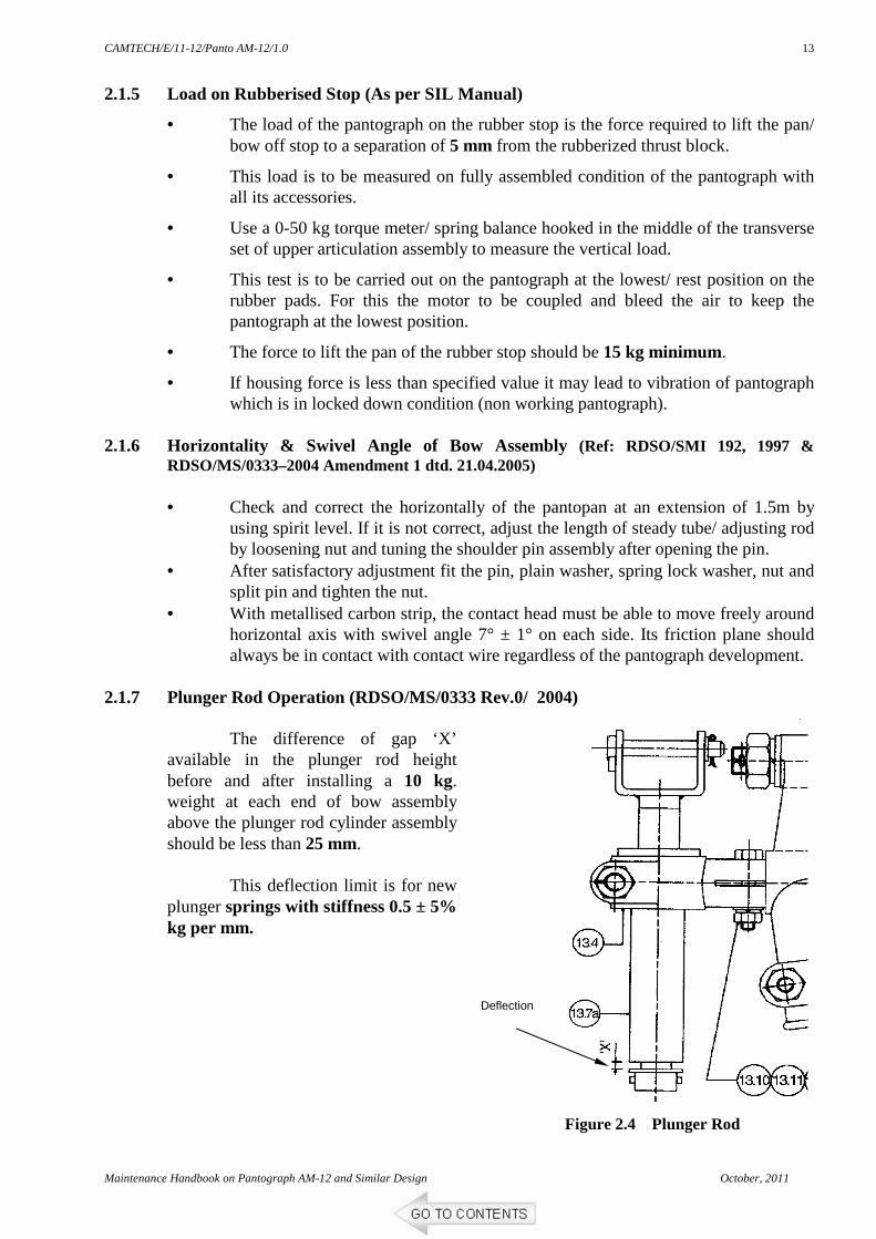
2.1.7 Plunger Rod Operation (RDSO/MS/0333 Rev.0/ 2004)
The difference of gap ‘X’ available in the plunger rod height before and after installing a 10 kg. weight at each end of bow assembly above the plunger rod cylinder assembly should be less than 25 mm.
This deflection limit is for new
plunger springs with stiffness 0.5 ± 5% kg per mm.
Deflection
Figure 2.4 Plunger Rod Operation
CAMTECH/E/11-12/Panto AM-12/1.0
October, 2011 Maintenance Handbook on Pantograph AM-12 and Similar Design
14
2.1.8 Leak Test of Servo Motor (As per SIL Manual) (not coupled with pantograph)
1. Supply compressed air at 10 kg/cm2 to the servo motor.
2. Apply soapy water by brush in all joints and check whether any leakage occurs.
3. Close the air inlet and note the maximum drop in pressure in 10 minutes. Maximum 5% drop is allowed.
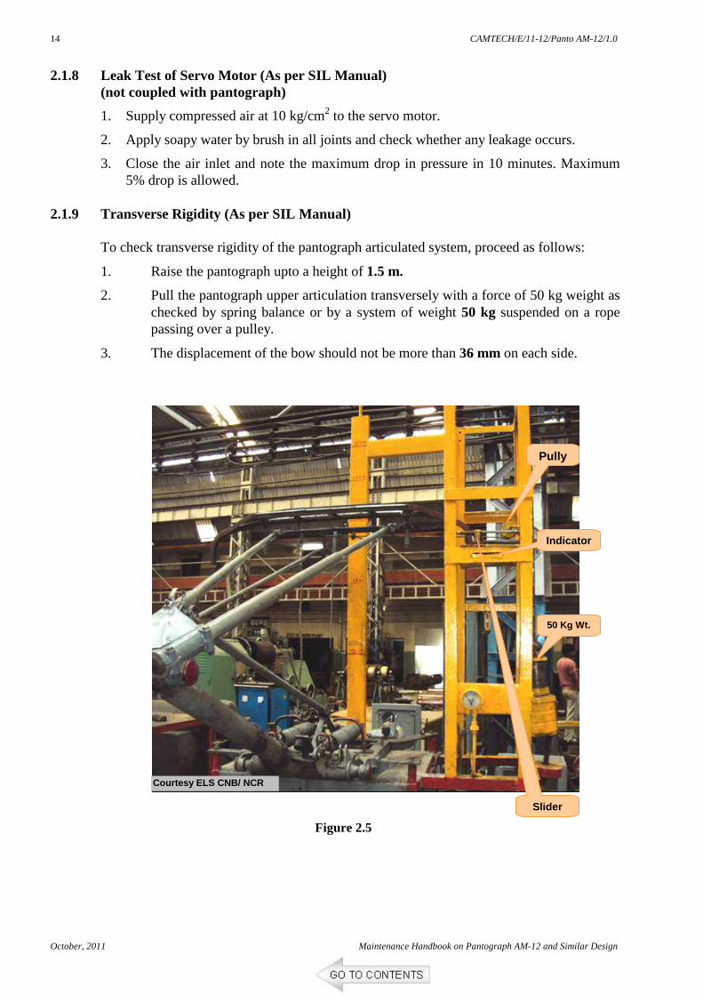
2.1.9 Transverse Rigidity (As per SIL Manual) To check transverse rigidity of the pantograph articulated system, proceed as follows:
1. Raise the pantograph upto a height of 1.5 m.
2. Pull the pantograph upper articulation transversely with a force of 50 kg weight as checked by spring balance or by a system of weight 50 kg suspended on a rope passing over a pulley.
3. The displacement of the bow should not be more than 36 mm on each side.
50 Kg Wt.
Pully
Indicator
Slider
Courtesy ELS CNB/ NCR
Figure 2.5
CAMTECH/E/11-12/Panto AM-12/1.0
Maintenance Handbook on Pantograph AM-12 and Similar Design October, 2011
15
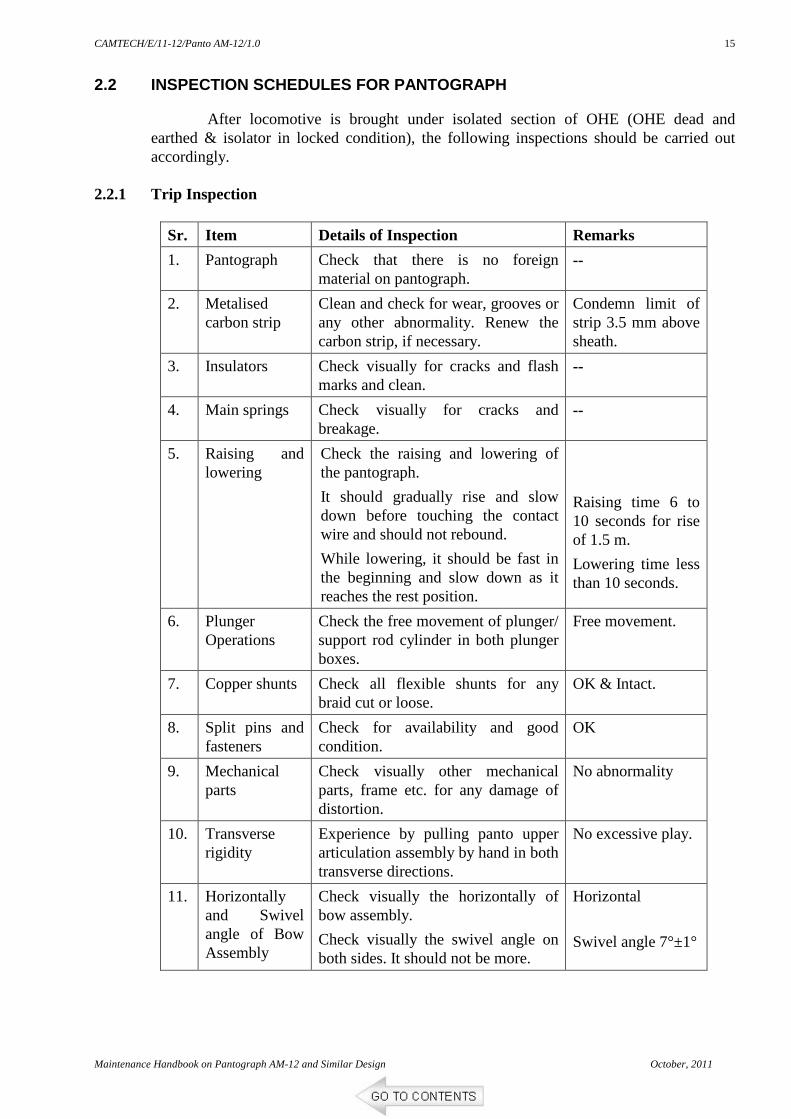
2.2 INSPECTION SCHEDULES FOR PANTOGRAPH
After locomotive is brought under isolated section of OHE (OHE dead and earthed & isolator in locked condition), the following inspections should be carried out accordingly.
2.2.1 Trip Inspection
Sr. Item Details of Inspection Remarks
1. Pantograph Check that there is no foreign material on pantograph.
--
2. Metalised carbon strip
Clean and check for wear, grooves or any other abnormality. Renew the carbon strip, if necessary.
Condemn limit of strip 3.5 mm above sheath.
3. Insulators Check visually for cracks and flash marks and clean.
--
4. Main springs Check visually for cracks and breakage.
--
5. Raising and lowering
Check the raising and lowering of the pantograph.
It should gradually rise and slow down before touching the contact wire and should not rebound.
While lowering, it should be fast in the beginning and slow down as it reaches the rest position.
Raising time 6 to 10 seconds for rise of 1.5 m.
Lowering time less than 10 seconds.
6. Plunger Operations
Check the free movement of plunger/ support rod cylinder in both plunger boxes.
Free movement.
7. Copper shunts Check all flexible shunts for any braid cut or loose.
OK & Intact.
8. Split pins and fasteners
Check for availability and good condition.
OK
9. Mechanical parts
Check visually other mechanical parts, frame etc. for any damage of distortion.
No abnormality
10. Transverse rigidity
Experience by pulling panto upper articulation assembly by hand in both transverse directions.
No excessive play.
11. Horizontally and Swivel angle of Bow Assembly
Check visually the horizontally of bow assembly.
Check visually the swivel angle on both sides. It should not be more.
Horizontal
Swivel angle 7°±1°
CAMTECH/E/11-12/Panto AM-12/1.0
October, 2011 Maintenance Handbook on Pantograph AM-12 and Similar Design
16
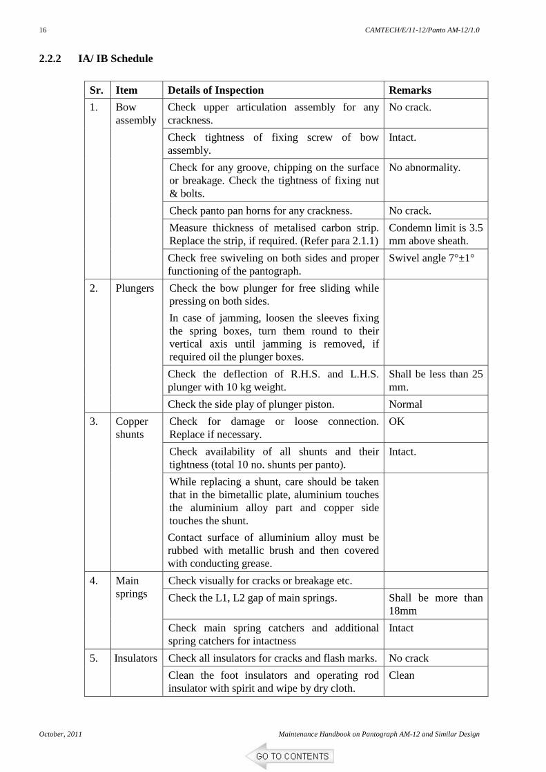
2.2.2 IA/ IB Schedule
Sr. Item Details of Inspection Remarks
Check upper articulation assembly for any crackness.
No crack.
Check tightness of fixing screw of bow assembly.
Intact.
Check for any groove, chipping on the surface or breakage. Check the tightness of fixing nut & bolts.
No abnormality.
Check panto pan horns for any crackness. No crack.
Measure thickness of metalised carbon strip. Replace the strip, if required. (Refer para 2.1.1)
Condemn limit is 3.5 mm above sheath.
1. Bow assembly
Check free swiveling on both sides and proper functioning of the pantograph.
Swivel angle 7°±1°
Check the bow plunger for free sliding while pressing on both sides.
In case of jamming, loosen the sleeves fixing the spring boxes, turn them round to their vertical axis until jamming is removed, if required oil the plunger boxes.
Check the deflection of R.H.S. and L.H.S. plunger with 10 kg weight.
Shall be less than 25 mm.
2. Plungers
Check the side play of plunger piston. Normal
Check for damage or loose connection. Replace if necessary.
OK
Check availability of all shunts and their tightness (total 10 no. shunts per panto).
Intact.
3. Copper shunts
While replacing a shunt, care should be taken that in the bimetallic plate, aluminium touches the aluminium alloy part and copper side touches the shunt.
Contact surface of alluminium alloy must be rubbed with metallic brush and then covered with conducting grease.
Check visually for cracks or breakage etc.
Check the L1, L2 gap of main springs. Shall be more than 18mm
4. Main springs
Check main spring catchers and additional spring catchers for intactness
Intact
Check all insulators for cracks and flash marks. No crack 5. Insulators
Clean the foot insulators and operating rod insulator with spirit and wipe by dry cloth.
Clean
CAMTECH/E/11-12/Panto AM-12/1.0
Maintenance Handbook on Pantograph AM-12 and Similar Design October, 2011
17
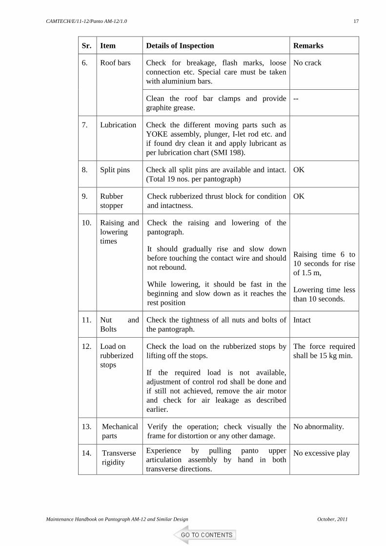
Sr. Item Details of Inspection Remarks
Check for breakage, flash marks, loose connection etc. Special care must be taken with aluminium bars.
No crack 6. Roof bars
Clean the roof bar clamps and provide graphite grease.
--
7. Lubrication Check the different moving parts such as YOKE assembly, plunger, I-let rod etc. and if found dry clean it and apply lubricant as per lubrication chart (SMI 198).
8. Split pins Check all split pins are available and intact. (Total 19 nos. per pantograph)
OK
9. Rubber stopper
Check rubberized thrust block for condition and intactness.
OK
10. Raising and lowering times
Check the raising and lowering of the pantograph.
It should gradually rise and slow down before touching the contact wire and should not rebound.
While lowering, it should be fast in the beginning and slow down as it reaches the rest position
Raising time 6 to 10 seconds for rise of 1.5 m,
Lowering time less than 10 seconds.
11. Nut and Bolts
Check the tightness of all nuts and bolts of the pantograph.
Intact
12. Load on rubberized stops
Check the load on the rubberized stops by lifting off the stops.
If the required load is not available, adjustment of control rod shall be done and if still not achieved, remove the air motor and check for air leakage as described earlier.
The force required shall be 15 kg min.
13. Mechanical parts
Verify the operation; check visually the frame for distortion or any other damage.
No abnormality.
14. Transverse rigidity
Experience by pulling panto upper articulation assembly by hand in both transverse directions.
No excessive play
CAMTECH/E/11-12/Panto AM-12/1.0
October, 2011 Maintenance Handbook on Pantograph AM-12 and Similar Design
18
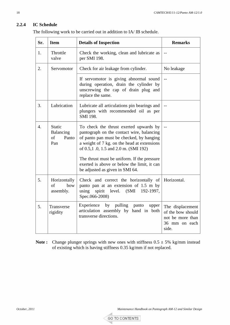
2.2.4 IC Schedule
The following work to be carried out in addition to IA/ IB schedule.
Sr. Item Details of Inspection Remarks
1. Throttle valve
Check the working, clean and lubricate as per SMI 198.
--
Check for air leakage from cylinder. No leakage 2. Servomotor
If servomotor is giving abnormal sound during operation, drain the cylinder by unscrewing the cap of drain plug and replace the same.
--
3. Lubrication
Lubricate all articulations pin bearings and plungers with recommended oil as per SMI 198.
--
4. Static Balancing of Panto Pan
To check the thrust exerted upwards by pantograph on the contact wire, balancing of panto pan must be checked, by hanging a weight of 7 kg. on the head at extensions of 0.5,1 .0, 1.5 and 2.0 m. (SMI 192)
The thrust must be uniform. If the pressure exerted is above or below the limit, it can be adjusted as given in SMI 64.
--
5. Horizontally of bow assembly.
Check and correct the horizontally of panto pan at an extension of 1.5 m by using spirit level. (SMI 192-1997, Spec.066-2008)
Horizontal.
5. Transverse rigidity
Experience by pulling panto upper articulation assembly by hand in both transverse directions.
The displacement of the bow should not be more than 36 mm on each side.
Note : Change plunger springs with new ones with stiffness 0.5 ± 5% kg/mm instead
of existing which is having stiffness 0.35 kg/mm if not replaced.
CAMTECH/E/11-12/Panto AM-12/1.0
Maintenance Handbook on Pantograph AM-12 and Similar Design October, 2011
19
2.2.5 Annual Overhauling Schedule (AOH)
Both pantographs are to be removed from locomotive and to be taken to the shed floor for overhauling. Servo motor and throttle valve are to be replaced with overhauled. Following works are to be carried out in addition to IC schedule.
o Servomotor
• Overhaul the servo motor and replace the items as mentioned in AOH kit.
• Measure the internal diameter of the cylinder. The maximum diameter allowed is 202.290 mm.
• Lubricate as per the SMI 198.
o Lubrication
• Clean and lubricate all articulation pins and ball bearings including articulation of thrust rod as per SMI 198.
o Isolating cocks
• Operate all isolating cocks by hand and put back to the previous position.
o Frame and other components
• Carry out the checks for bent, distortion, and cracks on frame and other components.
o Throttle valve
• Overhaul the throttle valve and replace items as mentioned in AOH kit and lubricate as per SMI 198.
All other assemblies of the pantograph to be checked and replace the items as mentioned in AOH kit (TC 0094).
Carry out all RDSO’s modifications if not done.
Carry out all the checks and test procedure as mentioned earlier in para 2.1. 2.2.6 IOH/ POH
Both pantographs, servo motors and throttle valves are to be removed from the locomotive and to be overhauled in the section.
Carry out all RDSO’s modifications if not done.
Items mentioned in IOH and POH kit to be replaced accordingly (TC 0094).
Carry out all the checks and test procedure as mentioned earlier in para 2.1.
CAMTECH/E/11-12/Panto AM-12/1.0
October, 2011 Maintenance Handbook on Pantograph AM-12 and Similar Design
20
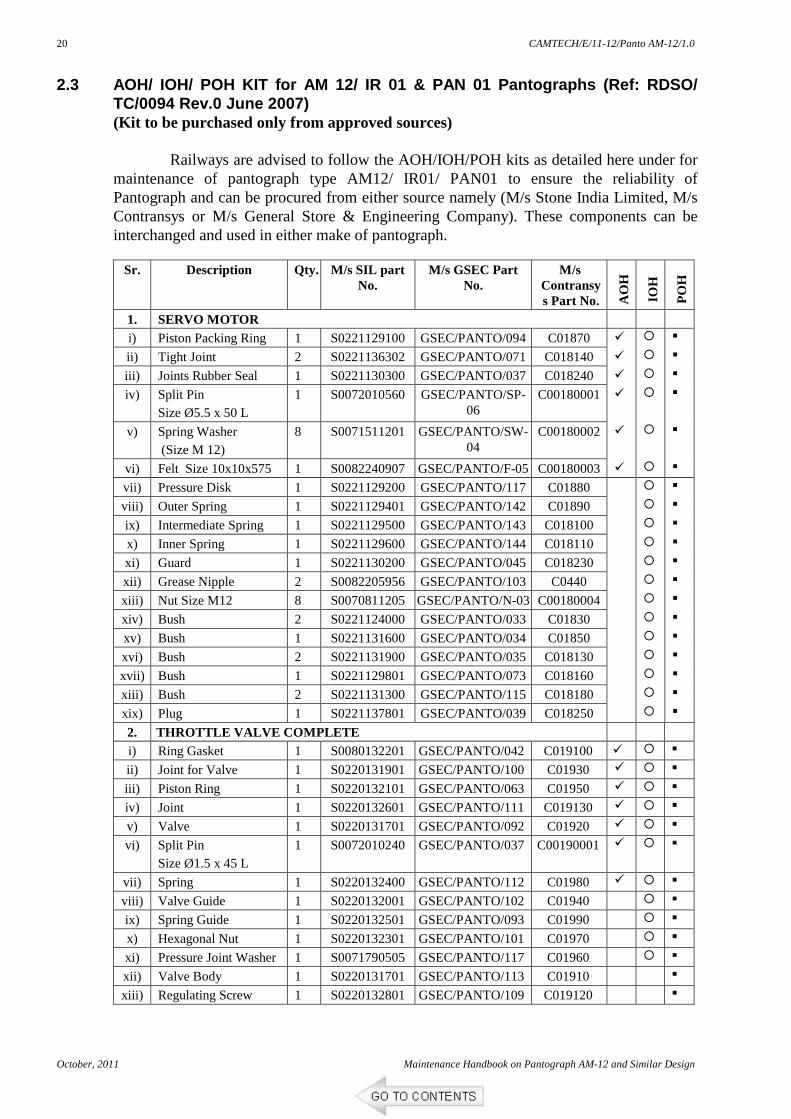
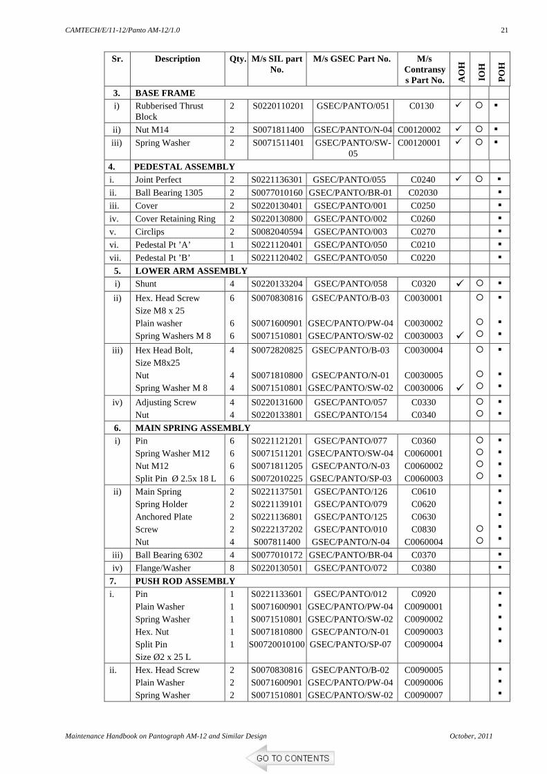
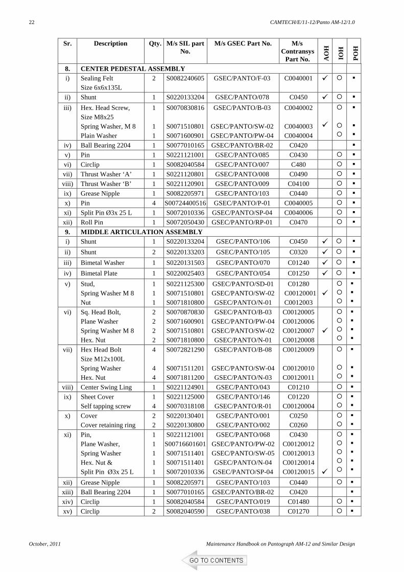
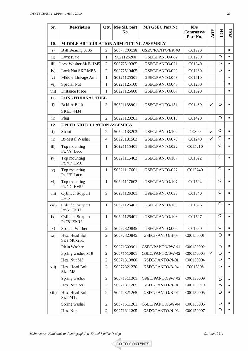
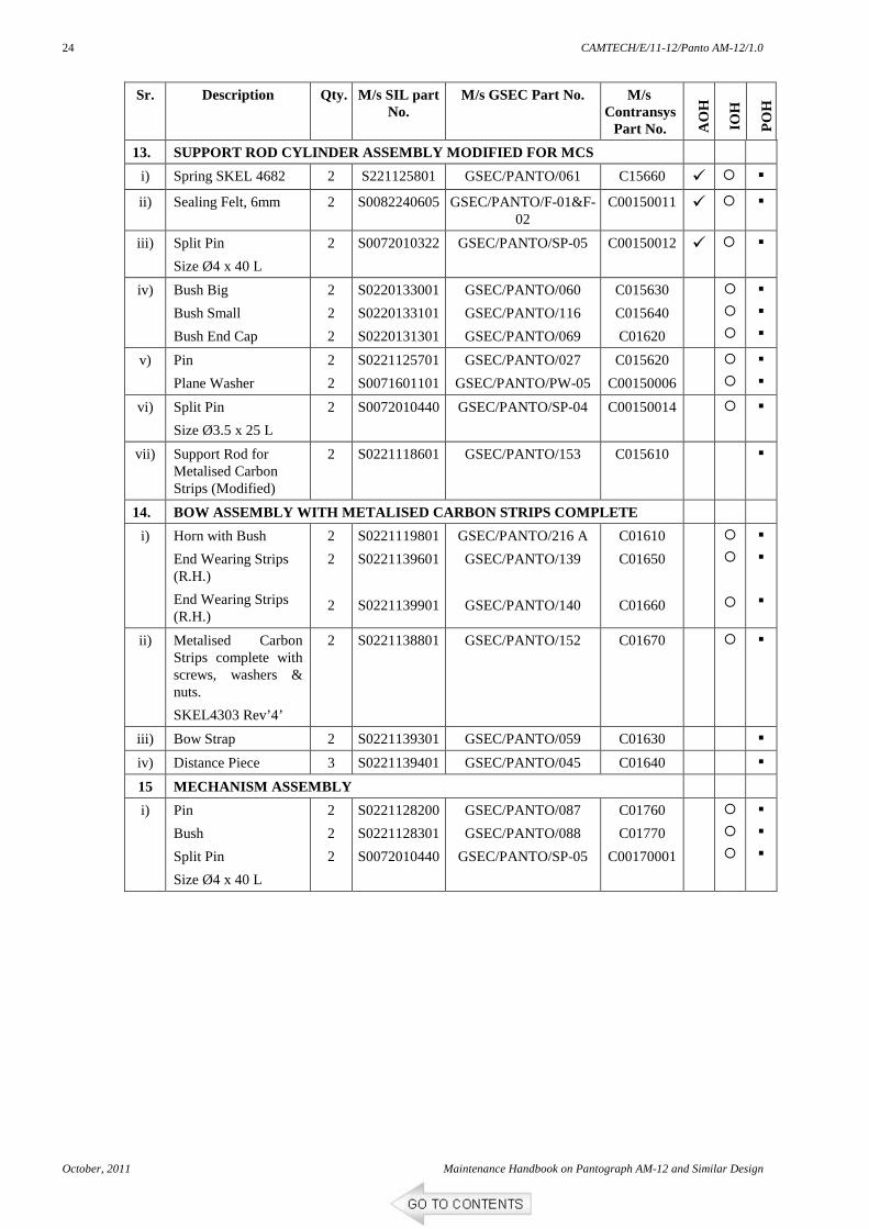
2.3 AOH/ IOH/ POH KIT for AM 12/ IR 01 & PAN 01 Pan tographs (Ref: RDSO/ TC/0094 Rev.0 June 2007) (Kit to be purchased only from approved sources)
Railways are advised to follow the AOH/IOH/POH kits as detailed here under for maintenance of pantograph type AM12/ IR01/ PAN01 to ensure the reliability of Pantograph and can be procured from either source namely (M/s Stone India Limited, M/s Contransys or M/s General Store & Engineering Company). These components can be interchanged and used in either make of pantograph.
Sr. Description Qty. M/s SIL part
No. M/s GSEC Part
No. M/s
Contransys Part No. A
OH
IOH
PO
H
1. SERVO MOTOR i) Piston Packing Ring 1 S0221129100 GSEC/PANTO/094 C01870
Maintenance Handbook on Pantograph AM-12 and Similar Design October, 2011
25
CHAPTER 3
RELIABILITY IMPROVEMENT MEASURES
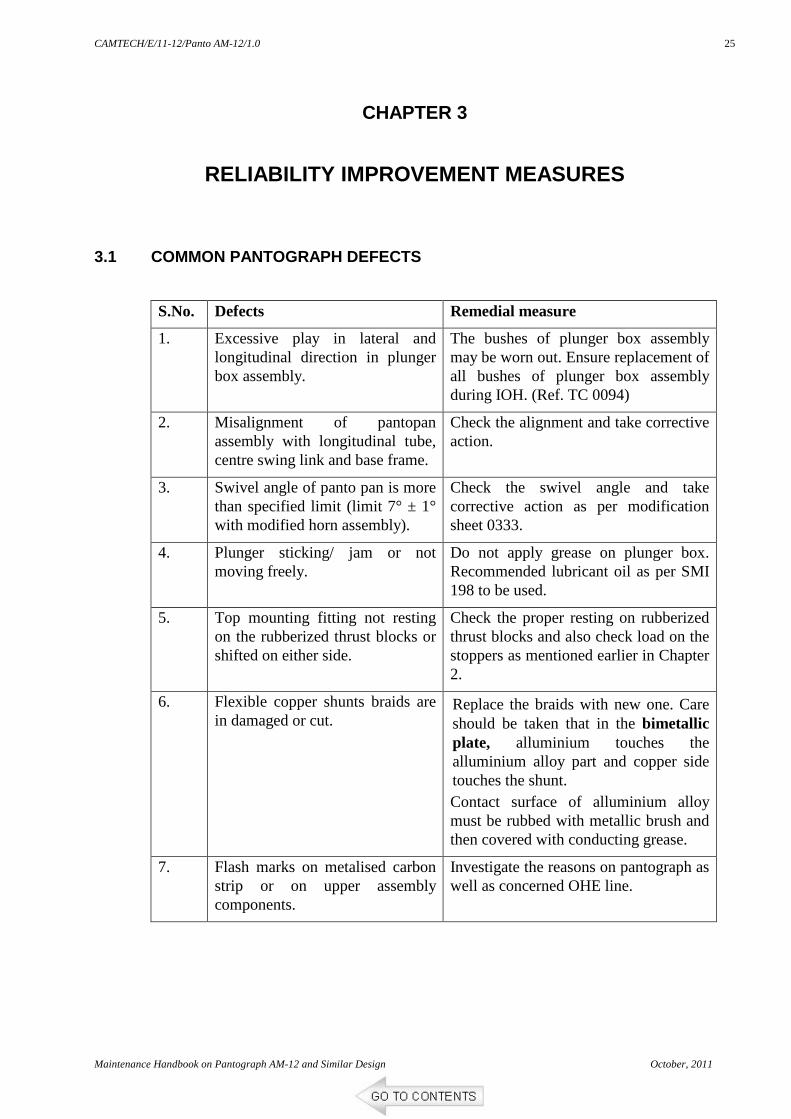
3.1 COMMON PANTOGRAPH DEFECTS
S.No. Defects Remedial measure
1. Excessive play in lateral and longitudinal direction in plunger box assembly.
The bushes of plunger box assembly may be worn out. Ensure replacement of all bushes of plunger box assembly during IOH. (Ref. TC 0094)
2. Misalignment of pantopan assembly with longitudinal tube, centre swing link and base frame.
Check the alignment and take corrective action.
3. Swivel angle of panto pan is more than specified limit (limit 7° ± 1° with modified horn assembly).
Check the swivel angle and take corrective action as per modification sheet 0333.
4. Plunger sticking/ jam or not moving freely.
Do not apply grease on plunger box. Recommended lubricant oil as per SMI 198 to be used.
5. Top mounting fitting not resting on the rubberized thrust blocks or shifted on either side.
Check the proper resting on rubberized thrust blocks and also check load on the stoppers as mentioned earlier in Chapter 2.
6. Flexible copper shunts braids are in damaged or cut.
Replace the braids with new one. Care should be taken that in the bimetallic plate, alluminium touches the alluminium alloy part and copper side touches the shunt. Contact surface of alluminium alloy must be rubbed with metallic brush and then covered with conducting grease.
7. Flash marks on metalised carbon strip or on upper assembly components.
Investigate the reasons on pantograph as well as concerned OHE line.
CAMTECH/E/11-12/Panto AM-12/1.0
October, 2011 Maintenance Handbook on Pantograph AM-12 and Similar Design
26
3.2 RECOMMENDATIONS
Ref : RDSO Investigation report No. RDSO/2011/EL/I R/0147, Rev.0, July 15, 2011 & other SMIs, MS & TCs
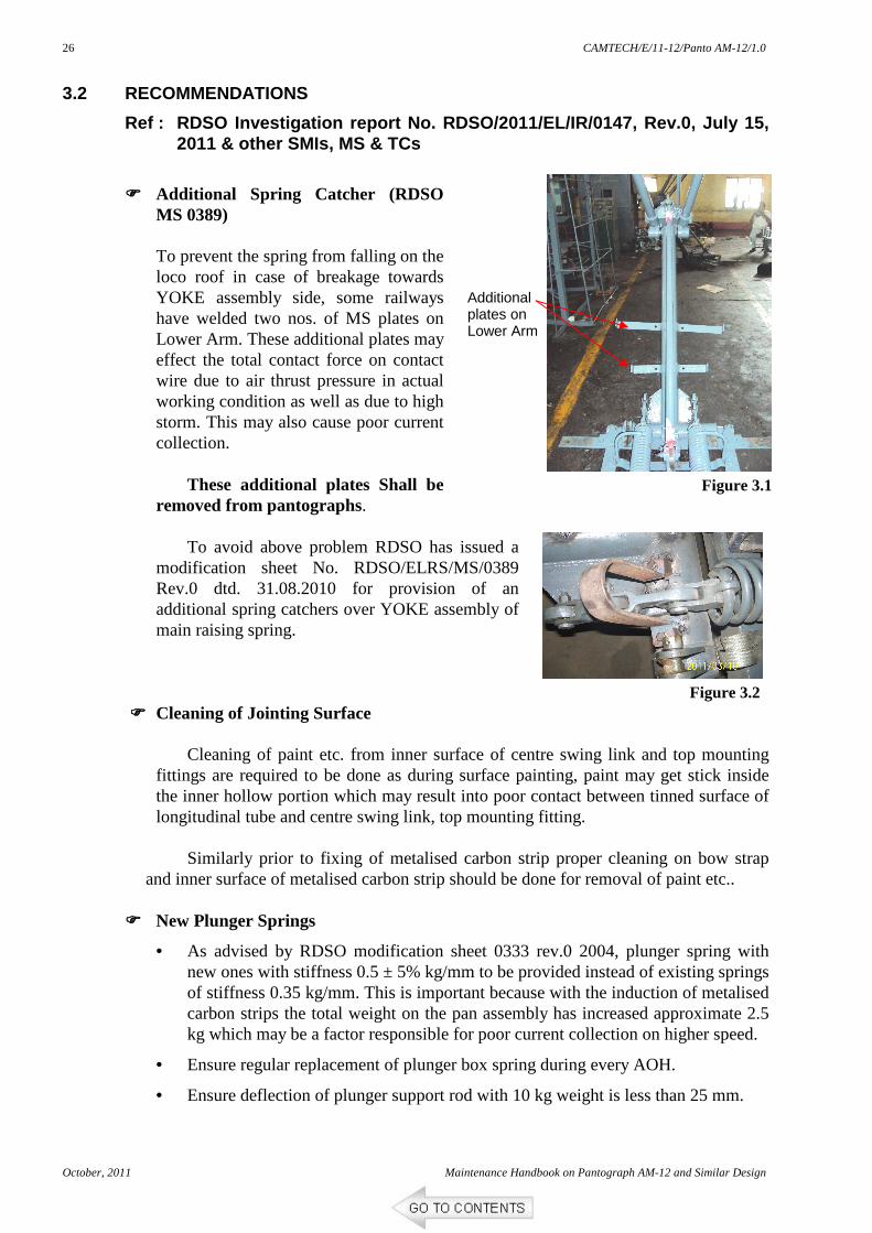
Additional Spring Catcher (RDSO
MS 0389)
To prevent the spring from falling on the loco roof in case of breakage towards YOKE assembly side, some railways have welded two nos. of MS plates on Lower Arm. These additional plates may effect the total contact force on contact wire due to air thrust pressure in actual working condition as well as due to high storm. This may also cause poor current collection.
These additional plates Shall be
removed from pantographs. To avoid above problem RDSO has issued a
modification sheet No. RDSO/ELRS/MS/0389 Rev.0 dtd. 31.08.2010 for provision of an additional spring catchers over YOKE assembly of main raising spring.
Cleaning of Jointing Surface Cleaning of paint etc. from inner surface of centre swing link and top mounting
fittings are required to be done as during surface painting, paint may get stick inside the inner hollow portion which may result into poor contact between tinned surface of longitudinal tube and centre swing link, top mounting fitting.
Similarly prior to fixing of metalised carbon strip proper cleaning on bow strap
and inner surface of metalised carbon strip should be done for removal of paint etc..
New Plunger Springs
• As advised by RDSO modification sheet 0333 rev.0 2004, plunger spring with new ones with stiffness 0.5 ± 5% kg/mm to be provided instead of existing springs of stiffness 0.35 kg/mm. This is important because with the induction of metalised carbon strips the total weight on the pan assembly has increased approximate 2.5 kg which may be a factor responsible for poor current collection on higher speed.
• Ensure regular replacement of plunger box spring during every AOH.
• Ensure deflection of plunger support rod with 10 kg weight is less than 25 mm.
Additional plates on Lower Arm
Figure 3.1
Figure 3.2
CAMTECH/E/11-12/Panto AM-12/1.0
Maintenance Handbook on Pantograph AM-12 and Similar Design October, 2011
27
All the split pins and fasteners may be procured from RDSO approved sources and split pins should not be reused.
Centre swing link and bushes of plunger box are to be replaced in every IOH.
Swivel angle of panto pan is to be restricted as 7° ± 1°.
Conduct transverse rigidity test at 1.5 m height with a weight of 50 kg in both directions and deflection should not be more than 36 mm on each side.
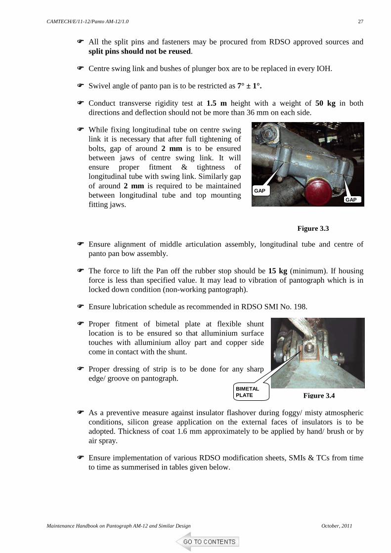
While fixing longitudinal tube on centre swing link it is necessary that after full tightening of bolts, gap of around 2 mm is to be ensured between jaws of centre swing link. It will ensure proper fitment & tightness of longitudinal tube with swing link. Similarly gap of around 2 mm is required to be maintained between longitudinal tube and top mounting fitting jaws.
Ensure alignment of middle articulation assembly, longitudinal tube and centre of panto pan bow assembly.
The force to lift the Pan off the rubber stop should be 15 kg (minimum). If housing force is less than specified value. It may lead to vibration of pantograph which is in locked down condition (non-working pantograph).
Ensure lubrication schedule as recommended in RDSO SMI No. 198.
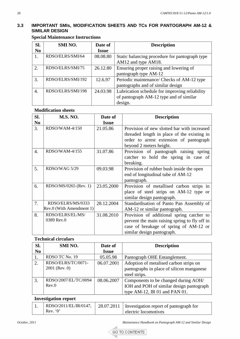
Proper fitment of bimetal plate at flexible shunt location is to be ensured so that alluminium surface touches with alluminium alloy part and copper side come in contact with the shunt.
Proper dressing of strip is to be done for any sharp edge/ groove on pantograph.
As a preventive measure against insulator flashover during foggy/ misty atmospheric conditions, silicon grease application on the external faces of insulators is to be adopted. Thickness of coat 1.6 mm approximately to be applied by hand/ brush or by air spray.
Ensure implementation of various RDSO modification sheets, SMIs & TCs from time to time as summerised in tables given below.
GAP
GAP
Figure 3.3
Figure 3.4 BIMETAL PLATE
CAMTECH/E/11-12/Panto AM-12/1.0
October, 2011 Maintenance Handbook on Pantograph AM-12 and Similar Design
28
3.3 IMPORTANT SMIs, MODIFICATION SHEETS AND TCs FOR PAN TOGRAPH AM-12 & SIMILAR DESIGN
Special Maintenance Instructions
Sl. No
SMI NO. Date of Issue
Description
1. RDSO/ELRS/SMI/64 08.08.80 Static balancing procedure for pantograph type AM12 and type AM18.
2. RDSO/ELRS/SMI/75 26.12.80 Ensuring proper raising and lowering of pantograph type AM-12
3. RDSO/ELRS/SMI/192 12.6.97 Periodic maintenance/ Checks of AM-12 type pantographs and of similar design
4. RDSO/ELRS/SMI/198 24.03.98 Lubrication schedule for improving reliability of pantograph AM-12 type and of similar design.
Modification sheets Sl. No
M.S. NO. Date of Issue
Description
3. RDSO/WAM-4/150 21.05.86 Provision of new slotted bar with increased threaded length in place of the existing in order to arrest extension of pantograph beyond 2 meters height.
4. RDSO/WAM-4/155 31.07.86 Provision of pantograph raising spring catcher to hold the spring in case of breaking.
5. RDSO/WAG 5/29 09.03.98 Provision of rubber bush inside the open end of longitudinal tube of AM-12 pantograph.
6. RDSO/MS/0265 (Rev. 1) 23.05.2000 Provision of metallised carbon strips in place of steel strips on AM-12 type or similar design pantograph.
7. RDSO/ELRS/MS/0333 Rev.0 (With Amendment 1)
28.12.2004 Standardisation of Panto Pan Assembly of AM-12 or similar pantograph.
8. RDSO/ELRS/EL/MS/ 0389 Rev.0
31.08.2010 Provision of additional spring catcher to prevent the main raising spring to fly off in case of breakage of spring of AM-12 or similar design pantograph.
2001 (Rev. 0) 06.07.2001 Adoption of metalised carbon strips on
pantographs in place of silicon manganese steel strips.
3. RDSO/2007/EL/TC/0094 Rev.0
08.06.2007 Components to be changed during AOH/ IOH and POH of similar design pantograph type AM-12, IR 01 and PAN 01.
Investigation report
1. RDSO/2011/EL/IR/0147, Rev. ‘0’
28.07.2011 Investigation report of pantograph for electric locomotives
CAMTECH/E/11-12/Panto AM-12/1.0
Maintenance Handbook on Pantograph AM-12 and Similar Design October, 2011
29
CHAPTER 4
PANTO ENTANGLEMENT
For smooth operation of locomotive, the movement of pantograph should be
unobstructed on the contact wire. Entanglement of pantograph with OHE normally takes place due to mechanical problems either in the OHE or with the pantograph. Entanglement can also take place during an accident or rough weather such as storm etc.
Pantograph entanglement causes damages to the pantograph and overhead equipment resulting in dislocation of electric traction traffic.
4.1 REASONS OF ENTANGLEMENT
Pantograph entanglement generally occurs due to the following reasons: o OHE defects o Pantograph defects o External defects
4.1.1 OHE Defects
Damaged OHE components such as insulators, cantilever tubes, jumpers, droppers etc. may foul with the movement of the pantograph and result in entanglement. The common OHE defects which may cause pantograph entanglement are as under:
i. Improper adjustment at turnouts and crossovers
Improper adjustment of stagger and height of contact wire at turnout or cross over results in pantograph getting entangled with overhead wire while moving on the main line.
ii. Mal functioning of ATD (auto tensioning device)
ATD keeps OHE in correct tension. If ATD drum is not moving freely, the OHE tension will not remain correct. This will cause sag in OHE at higher temperature and in cold wheather OHE wire may break. Any sag in OHE is prone to panto entanglement when pantograph is moving at high speed. Ensure free movement of ATD.
iii. Failure of manufacturing joints of contact wire.
Contact wire consists of joints within the running length. These joints are made during manufacturing. Their failure results in snapping of contact wire. If a locomotive is moving in the same zone where such a snapping takes place, panto entanglement will result. Therefore it is necessary to check frequently such joints, specially those in the polluted areas where they are prone to more failures.
iv. Damaged OHE components
Damaged OHE components such as failure of insulators due to corrosion/ flashover, working out of fixtures, PG clamps, splices, bolts etc. may also contribute in pantograph entanglement.
Apart from the above, if locomotive goes in unwired section by mistake it may damage both the panto and 9-t insulators. To avoid this, it should be ensured that loco stop caution boards are placed at correct locations properly.
CAMTECH/E/11-12/Panto AM-12/1.0
October, 2011 Maintenance Handbook on Pantograph AM-12 and Similar Design
30
4.1.2 Pantograph Defects
The common defects of pantograph which may cause pantograph entanglement are as under:
i. Spring box failure.
Spring box failure contributes in pantograph entanglement. To check for any cracks, Dye Penetration Test should be carried out in cylinder, welding portion of the steady link, cylinder support and sub mounting assembly. Proper lubrication of plunger ensures dampening of vibrations of panto pan and prevents cracks in plunger sockets. Plungers should move freely inside the spring box.
ii. Improper static forces on OHE.
The static force which pantograph exerts on the contact wire prevents undue oscillations to OHE pantograph system while the locomotive is in motion. This static force is normally kept at 7 kg. If this static force is less, a large oscillation will cause the pantograph to leave its contact with OHE resulting in sparking and local heating, which may damage the contact wire. If this static force is more then friction between panto pan strip and contact wire will increase.
iii. Missing pins and fasteners.
Provision of split pins shall be ensured during every inspection and also whenever the panto pan is changed. The split pins at critical locations of articulation arrangement and full complement of copper shunt helps in reducing pantograph defects. The split pins should be opened out up to 60 degrees, so that they do not work out during running.
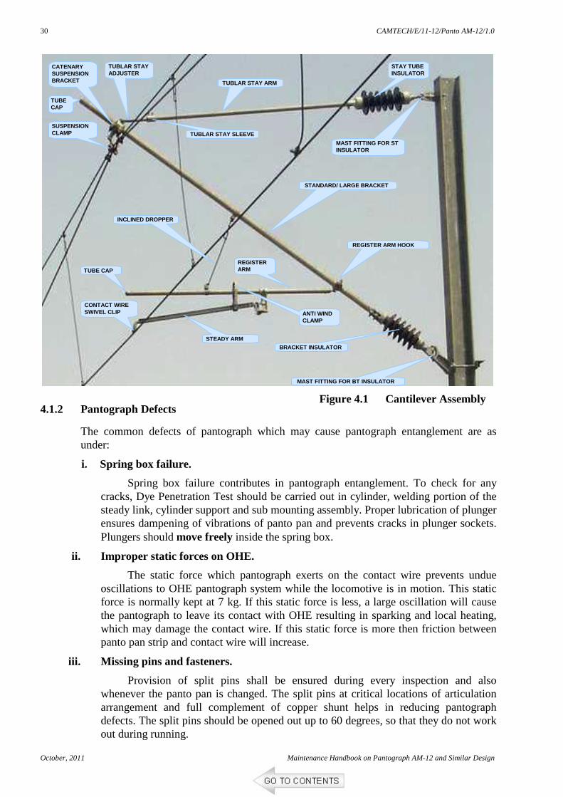
TUBE CAP
TUBLAR STAY ADJUSTER
CATENARY SUSPENSION BRACKET TUBLAR STAY ARM
TUBLAR STAY SLEEVE
STAY TUBE INSULATOR
MAST FITTING FOR ST INSULATOR
STANDARD/ LARGE BRACKET
REGISTER ARM HOOK
MAST FITTING FOR BT INSULATOR
BRACKET INSULATOR
STEADY ARM
CONTACT WIRE SWIVEL CLIP
INCLINED DROPPER
SUSPENSION CLAMP
TUBE CAP
ANTI WIND CLAMP
REGISTER ARM
Figure 4.1 Cantilever Assembly
CAMTECH/E/11-12/Panto AM-12/1.0
Maintenance Handbook on Pantograph AM-12 and Similar Design October, 2011
31
iv. Cracks in mechanical parts.
The effect of broken and missing components of pantograph such as cracks in plunger, balancing rod and articulation rod lead to damage of panto pan, ultimately resulting in panto entanglement during run.
v. Working out of base insulator bolts.
This may cause excessive vibrations in pantograph assembly under dynamic conditions and may contribute in pantograph entanglement.
vi. Improper leveling of panto pan.
Improper leveling of pantograph pan leads to tilting of pantograph pans. Horizontally of pantopan shall be ensured during every inspection and also whenever the panto pan is changed.
4.1.3 External Defects i. Displacement of OHE caused by mast deflection due to wind/ Storm
ii. External object hitting OHE (Bird hitting/ Monkey Electrocution)
iii. Tree branches/Foreign materials on OHE
iv. Theft
v. Change in track alignment and level
4.2 INVESTIGATION AFTER ENTANGLEMENT
Once the pantograph entanglement happens it becomes rather very difficult to establish the defect of the loco pantograph or the OHE. It is a great effort to be made to find out either OHE failed first or the pantograph. For this purpose all the evidences are to be preserved.
The officer or supervisor of the electrical department arriving first at site of break down, particularly those involving entanglement of pantograph with the OHE, should make a very careful note of all relevant details pertaining to breakdown and also prepare a sketch indicating the particulars. He will also arrange for preservation of such evidence as may be useful for investigating the cause of breakdown/ entanglement.
Items to be checked on the pantograph and OHE are indicated in proformas I & II.
Maintenance staff, after ensuring that OHE is dead, and earthed in association with OHE staff will climb on the roof the locomotive. They will remove the HPT links of the damaged pantograph and earth it and will secure the pantograph with wire rope from the base frame of the pantograph in such a manner that it does not come in contact with OHE during the run.
• Prepare a statement stating following: o Loco No., panto (leading or trailing), Train No., name of driving crew, time etc. o OHE location No., type of location i.e. turnout, over-lap section insulator etc. o Record the damages/ breakages of parts of OHE and panto. This should include
the nature of damage/ breakage i.e. bent, broken, crack, hitting, rubbing, flash marks etc. on panto parts and OHE.
o Any foreign material found on OHE or roof of loco should also be collected and recorded.
• Record the statement of driving crew, station staff or engineering staff (if any) available and have been seen by them during the failure or before/after the failure.
CAMTECH/E/11-12/Panto AM-12/1.0
October, 2011 Maintenance Handbook on Pantograph AM-12 and Similar Design
32
4.3 PREPARATION OF JOINT NOTE
Normally it should be prepared jointly by TRD and TRO/TRS staff. However, if no such staff is made available a first hand joint note should be prepared along with staff of other department. Final joint note can be made at a later stage at loco shed or station. The final joint note should always carry the final conclusion and fixing up the responsibility. But in case it can not be arrived, the matter should be referred to higher ups. However as far as possible the cause of failure should be established.
The points given below should also be borne in mind during investigation.
4.3.1 OHE Defects
• In case of breakage of bracket tube insulator
If bracket tube insulator failure have resulted in damage and entanglement of pantograph, then there will always be following evidences.
o A hit mark on front portion of the locomotive.
o Flash mark will also be available on the front portion near roof.
o Headlight of locomotive may get damage.
o The bracket tube will also have the hitting mark and may be bent.
o Front pantograph that may be in lowered condition may get hitting mark.
• In case of breakage of registration tube/ steady tu be or associated fitting
o These tubes will hang below the contact wire level and entangle with pantograph.
o Panto pan will have hit mark or break.
o There will be chipping, kink or twist on contact wire since panto will drag the broken tubes ahead.
o In case of curved track location the stagger will be out and the panto may go off the contact wire which may damage droppers or even rubbing on catenary wire.
• In case of failure of stay tube insulator
In case of stay tube insulator failure, the cantilever will rest on contact wire there by the height of OHE will come down. Whenever any of the components of cantilever projected below the contact wire level, it may cause pantograph entanglement then:
o Pantograph will have the hitting mark.
o Part of cantilever hitting the panto pan will also get bent, or broken.
• In case of open jumpers/ droppers
These may or may not hang below the contact wire level. However if just on contact wire, they may entangle with panto pan because of push-up of contact wire. In this case:
o Panto may not have hitting mark but will be bent or broken.
o The jumper/ dropper entangled with panto will be pulled.
o The jumper/ dropper will be dragged along with PG clamps at catenary; thus there will be scratch marks on strands.
CAMTECH/E/11-12/Panto AM-12/1.0
Maintenance Handbook on Pantograph AM-12 and Similar Design October, 2011
33
• In case of section insulator failure o There will be heavy hitting on panto pan and the runners. o Runners may badly bent and also heavy chipping will be observed. o Several petticoats of insulator may shear out.
• Turnouts/ Crossovers
Turnouts are such adjusted that the contact wire of secondary line remains 50 mm above the main line contact wire. The emergency crossovers in between up and down main line are also equipped similar to turnouts. The entanglement happens on trailing turnout when its contact wire is below the main line contact wire and the separation between them is not adequate. Once the horn of pantograph damage/ break, panto looses its balance and further entangles.
4.3.2 Defects of Pantograph
• Broken/ damaged spring box, its pin etc.
Spring boxes are provided to keep the uniform push up of panto pan in all conditions. If any of the part of spring box is broken, the alignment of panto pan gets disturbed. The pan does not remain in horizontal position and because of its running in inclined position it causes entanglement.
• Broken Upper tube frame
In case of any damage or breakage of upper tube frame i.e. bent, twist etc. the panto pan also tilted and results in entanglement.
• Failure of positioning link
The positioning link is a pipe, which connects middle articulation to the transverse rod of the panto pan. This link keeps the panto pan in position. However failure of any parts of this link that is pin, rod etc. panto pan reverses up side down and panto pan entangled with the OHE.
• Broken support insulators
Four support insulators are used to support complete assembly of pantograph and to insulate it from body of locomotive. In case of breakage of any of insulator or its parts the complete assembly of pantograph tilts which means the panto pan may not travel in horizontal position and will entangle with OHE.
• Damage/ broken middle articulation
Middle articulation is an assembly connecting lower arm and upper tube of the pantograph. The joint is very important to keep upper tube in plane and then the panto pan in perfect horizontal position. In case of any damage or misalignment of this assembly, the panto pan will not travel in normal condition and will entangle with OHE.
• Damaged/ disconnected/ bent longitudinal tubes There are two such tubes in pantograph assembly which connects middle
articulation to panto pan. In case of failure, misalignment etc. the horizontally of panto pan is disturbed and liable for entanglement with OHE.
It is not advisable to come to conclusion at first instance, but it may be always good to study the case and hear the witnesses to come to conclusion. No hurry is to be made but a thorough study of parts; situation, evidence, direction, speed etc. are to be considered.
CAMTECH/E/11-12/Panto AM-12/1.0
October, 2011 Maintenance Handbook on Pantograph AM-12 and Similar Design
34
4.4 CHECKS AFTER PANTOGRAPH ENTANGLEMENT
Even after ensuring all above precautionary items, panto entanglement may occur. In such cases, it is necessary to quickly check the following items pertaining to the OHE and pantograph. This should be done without causing any delay in the restoration work.
• Measurements
The Measurement so recorded should tally with the measurement in structure erection drawing for entanglement locations (marked on OHE mast). It should also be checked whether steady arm holding contact wire is freely moving vertically or not.
• Location of Hit Marks
Search for hit mark in steady arm & the registration arm tube, PG clamps, droppers, contact wire, dropper clip, splice and jumpers. Any hit mark observed in these locations should be noted.
• Condition of cracked OHE fittings
The condition of cracked OHE fittings such as clamps, suspension brackets and contact wire clips should be checked to record whether the cracks are fresh or old.
• Pantograph wearing Strips
Pantograph metalised carbon strips should be properly fastened with panto pan. There should be no deep grooves. There should be no gap between strip joints.
• Availability of split pins
Check availability of split pins in pantograph assembly.
• Broken components of pantograph
The broken parts of pantograph should be inspected to check whether cracks are fresh or old.
• Measurements of pantograph
Measurements of good AM-12 & similar design pantograph should be A = 520, B = 1800, C = 300 and D = 380 as shown in figure. All dimensions are in mm.
AA
D
C
B
CAMTECH/E/11-12/Panto AM-12/1.0
Maintenance Handbook on Pantograph AM-12 and Similar Design October, 2011
35
PROFORMA ‘I’
PANTOGRAPH-ITEMS OF CHECK IN CASE OF ENTANGLEMENT (Ref : ACTM Vol III 1994 Annexure 9.02)
S. N Items Of Check Standard Actual
Observation
1. Metalised Carbon strips Fastening
1. Proper fastening 2. No loose fastener 3. No broken strip 4. No deep grooves 5. Smooth strip Joints 6. No hindrance to smooth riding
of contact wire on the pan.
2. Bow plunger 1. Free sliding while pressing. 2. Availability of all split pins.
3. Horizontality of panto pan and its free vertical movement.
Transverse flexibility of panto pan by pulling transversely at middle of cross member with 50-Kg force.
1. Displacement of the pan at the middle cross member should not exceed 36 ± 5 mm.
5. Positioning link 1. No bend 2. No crack 3. No dislocation from fixing pivots.
6. Split pins All split pins intact.
7. Pantograph frame 1. No signs of bending. 2. No cracks on main spring.
8. Broken, cracked fitting 1. No old crack. 2. No fresh crack.
9. Panto pan measurement in mm
AM-12 A- 520 B- 1800 C- 300 D- 380
Signature:
Name:
Designation:
OHE LOCO LOCO (OP) Representative Representative Representative
CAMTECH/E/11-12/Panto AM-12/1.0
October, 2011 Maintenance Handbook on Pantograph AM-12 and Similar Design
36
PROFORMA ‘II’
OHE - ITEMS OF CHECK IN CASE OF ENTANGLEMENT (Ref : ACTM Vol III 1994 Annexure 9.03)
S. N Items Of Check Standard Actual Observation
1. Location 2. Contact wire height- at main line H
3. Contact wire height- at turn out/ cross over above R.L.
H + 50 mm above main line
4. Stagger of contact wire of main line. 200 mm (max.)
5. Contact wire stagger – at turn out/cross over.
300 mm (max.)
6. Steady arm length holding main line contact wire.
750 mm to 950 mm
7. Steady arm length holding contact wire of turn out/ cross over
1150mm -1350mm
8. Position of registration tube Horizontal
9. Position of register arm dropper clip No displacement.
10. Track separation at obligatory point. 150-700 mm.
11. Position at which horn of pantograph jumped above contact wire.
Should not jump.
12. Vertical height steady arm clamp from register arm.
250 mm – 300 mm
13. Hitting marks on steady arm, Registration arm tube, PG clamp, dropper, contact wire, dropper clip splices, jumper
No hitting mark, looseness breakage or crack
14. Condition of cracked or broken OHE fittings such as clamps, catenary suspension bracket, splices and clips etc.
No old or fresh crack.
15. Steady arm vertical movement Free movement Note : Above observation will be made on every mast within atleast 500 m in the rear of the
location of entanglement.
Signature:
Name:
Designation:
OHE LOCO LOCO (OP) Representative Representative Representative In addition to above (Checks according to Proforma I and II), the following parameters should also be observed and recorded: • Climatic condition. • Track parameters/ condition. • Recent work done on the track. • Adjustment of turnout cross over last done.
CAMTECH/E/11-12/Panto AM-12/1.0
Maintenance Handbook on Pantograph AM-12 and Similar Design October, 2011
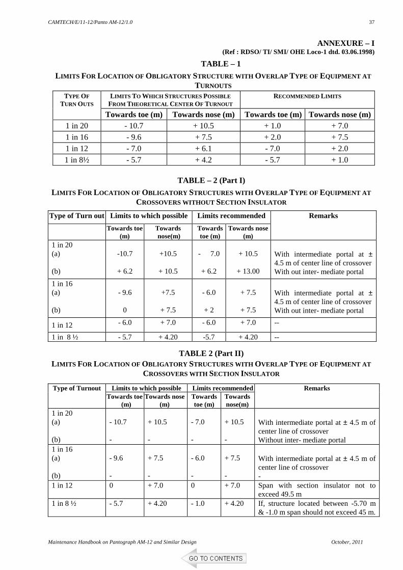
L IMITS FOR LOCATION OF OBLIGATORY STRUCTURE WITH OVERLAP TYPE OF EQUIPMENT AT
TURNOUTS
L IMITS TO WHICH STRUCTURES POSSIBLE
FROM THEORETICAL CENTER OF TURNOUT RECOMMENDED L IMITS TYPE OF
TURN OUTS
Towards toe (m) Towards nose (m) Towards toe (m) Towards nose (m) 1 in 20 - 10.7 + 10.5 + 1.0 + 7.0
1 in 16 - 9.6 + 7.5 + 2.0 + 7.5
1 in 12 - 7.0 + 6.1 - 7.0 + 2.0
1 in 8½ - 5.7 + 4.2 - 5.7 + 1.0
TABLE – 2 (Part I)
L IMITS FOR LOCATION OF OBLIGATORY STRUCTURES WITH OVERLAP TYPE OF EQUIPMENT AT
CROSSOVERS WITHOUT SECTION INSULATOR
Type of Turn out Limits to which possible Limits recommended
Towards toe (m)
Towards nose(m)
Towards toe (m)
Towards nose (m)
Remarks
1 in 20 (a) (b)
-10.7
+ 6.2
+10.5
+ 10.5
- 7.0
+ 6.2
+ 10.5
+ 13.00
With intermediate portal at ± 4.5 m of center line of crossover With out inter- mediate portal
1 in 16 (a) (b)
- 9.6
0
+7.5
+ 7.5
- 6.0
+ 2
+ 7.5
+ 7.5
With intermediate portal at ± 4.5 m of center line of crossover With out inter- mediate portal
1 in 12 - 6.0 + 7.0 - 6.0 + 7.0 --
1 in 8 ½ - 5.7 + 4.20 -5.7 + 4.20 --
TABLE 2 (Part II)
L IMITS FOR LOCATION OF OBLIGATORY STRUCTURES WITH OVERLAP TYPE OF EQUIPMENT AT
CROSSOVERS WITH SECTION INSULATOR
Limits to which possible Limits recommended Type of Turnout Towards toe
(m) Towards nose
(m) Towards toe (m)
Towards nose(m)
Remarks
1 in 20 (a) (b)
- 10.7 -
+ 10.5 -
- 7.0 -
+ 10.5 -
With intermediate portal at ± 4.5 m of center line of crossover Without inter- mediate portal
1 in 16 (a) (b)
- 9.6 -
+ 7.5 -
- 6.0 -
+ 7.5 -
With intermediate portal at ± 4.5 m of center line of crossover -
1 in 12 0 + 7.0 0 + 7.0 Span with section insulator not to exceed 49.5 m
1 in 8 ½ - 5.7 + 4.20 - 1.0 + 4.20 If, structure located between -5.70 m & -1.0 m span should not exceed 45 m.
CAMTECH/E/11-12/Panto AM-12/1.0
October, 2011 Maintenance Handbook on Pantograph AM-12 and Similar Design
38
Notes:
1. All distances are measured with respect to center of turnout.
2. In the tables above '–' sign is used for distances measured from theoretical center of turn out towards toe of switch and '+' sign is used for distances measured from theoretical center of turnout towards nose of crossing.
3. Theoretical center of turnout is the imaginary point of intersection of the centerline of the main track with the extended centerline of the straight portion of turnout track beyond the nose of crossing.
CAMTECH/E/11-12/Panto AM-12/1.0
Maintenance Handbook on Pantograph AM-12 and Similar Design October, 2011
39
FORMAT FOR RECORDING THE OBSERVATIONS/ MEASUREMENTS _________ RAILWAYS _________________ DIVISION
TRACTION DISTRIBUTION BRANCH TURNOUT/CROSSOVER NO.
S. N. ITEMS STANDARD VALUE
MEASURED VALUE
Particulars of Turnouts/Crossover
Section
Location No.
1
Date checked
2 Type of Arrangement – Crossed type/ Overlap Type
Main Line Contact Wire (m), H 3 Height of contact wire above rail level at obligatory structure
Turnout Contact Wire (m) H + 50 mm
4 Turn out span 54 m, Max.
Main Line Contact Wire (m)
H 5 Height of contact wire in overlapping zone
Turnout Contact Wire (m) H + 50 mm
Mainline contact Wire (m) 200 mm (Max.)
6
Stagger of contact wire at obligatory structure
Turnout Contact Wire (m) 300 mm (Max.)
7 Sag of Section insulator at Turnout/Crossover (mm) Zero
8 Movement of tower wagon from mainline to turnout a) Take off b) Point of take off (in meters from support)
670+20 mm
9 Movement of tower wagon from turnout to mainline c) Take on d) Point of take on (in meters from support)
670+20 mm
10 Stagger of section insulator at Turnout/Crossover. ± 100 mm
11 Track centers at the location of section insulator a) Runners towards the center of turnout b) Runners away from the center of turnout
1.65 m (Min.) 1.45 m (Min.)
12 Condition of ATD of turnout/mainline OHE Free to move
13 Length of tube provided in anti-falling device to bridge redundant length
30 cm to 45 cm
14 Setting distance of obligatory structure 3.0 m (Min.)
15 Track centers at obligatory structure 150 mm to 700 mm
16 Distance of ‘G’ jumpers from obligatory structure 5.6 m
17 Deviation from SEDs
18 Adjustments done, if any
19 Remarks
Name of supervisor and designation. Signature of supervisor.
CAMTECH/E/11-12/Panto AM-12/1.0
October, 2011 Maintenance Handbook on Pantograph AM-12 and Similar Design
40
REFERENCE
1. Operation and Maintenance Manual for Stone – Favieley Pantograph Type AM-12, AM-12B for Electric Locomotives and Electric Multiple Unit issued by Stone India Ltd. Kolkatta.
2. Maintenance Manual of Pantograph Type GSEC/ PAN – 01 for AC Electric Locomotives and Electric Multiple Unit issued by General Stores and Engineering Co. Kolkatta.
3. AC Traction Manual Vol. III 1994.
4. Various Modifications Sheets, Special Maintenance Instructions, Technical Circulars, Specifications, Investigation Reports issued by RDSO on the Pantograph Type AM-12 and similar design as mentioned in this book.
5. Field visits of Electric Loco Sheds/ workshops.
6. RDSO TI/SMI/OHE Loo-1 dtd. 03.06.1998 for Panto Entanglements and Over-head Equipment (OHE) on Turnout/ Crossovers.
7. Suggestions received from participants during seminar held at CAMTECH, Gwalior on date 16.09.2011.


![ööööÀÀÀhhh$$HHHH · yyyZZyZZ0000+{{{{gggzzgzZZzZ]]]Z]ggggúúúú öööö ÀÀÀhhh$$$ZZZZRRRR,yyyyCCCC HHHH ~~~~ gònnnncccc***ggg:ÀÀÀÀFFFF,,, îîîîYYYYƒƒƒƒqqqq---ZZZ!!!Z](https://static.documents.pub/doc/80x56/5e2294b0108ac463275cc30b/hhhhhhh-yyyzzyzz0000gggzzgzzzzzzgggg-hhhzzzzrrrryyyycccc.jpg)


