8/16/2019 MMs Lect Ch-12 of 24Apr 14
http://slidepdf.com/reader/full/mms-lect-ch-12-of-24apr-14 1/31
The x86 PC Assembly Language, Design, and Interfacing
By Muhammad Ali Mazidi, Janice Gillespie Mazidi and Danny Causey
© 2010, 2003, 2000, 1998 Peas!n "i#he $duca%i!n, &nc'
Peas!n Pen%ice "all ( )ppe *addle +ie, -J 0./8
Ch Twelve
INTERFACINGTO LCD, MOTOR,
ADC, AND SENSOR
8/16/2019 MMs Lect Ch-12 of 24Apr 14
http://slidepdf.com/reader/full/mms-lect-ch-12-of-24apr-14 2/31
8/16/2019 MMs Lect Ch-12 of 24Apr 14
http://slidepdf.com/reader/full/mms-lect-ch-12-of-24apr-14 3/31
The x86 PC Assembly Language, Design, and Interfacing
By Muhammad Ali Mazidi, Janice Gillespie Mazidi and Danny Causey
© 2010, 2003, 2000, 1998 Peas!n "i#he $duca%i!n, &nc'
Peas!n Pen%ice "all ( )ppe *addle +ie, -J 0./8
12.4: INTERFACING TO ADC CHIPS & SENSORSADC devices
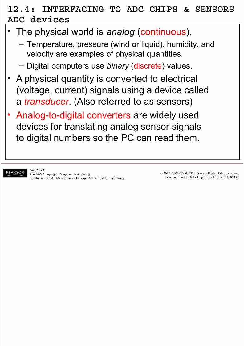
• The physical world is analog (continuous).
– Temperature, pressure (wind or liquid), humidity, andvelocity are examples of physical quantities.
– Digital computers use binary (discrete) values,
• physical quantity is converted to electrical
(voltage, current) signals using a device called
a transducer . (lso referred to as sensors)
• nalog!to!digital converters are widely used
devices for translating analog sensor signalsto digital num"ers so the #$ can read them.
8/16/2019 MMs Lect Ch-12 of 24Apr 14
http://slidepdf.com/reader/full/mms-lect-ch-12-of-24apr-14 4/31
8/16/2019 MMs Lect Ch-12 of 24Apr 14
http://slidepdf.com/reader/full/mms-lect-ch-12-of-24apr-14 5/31
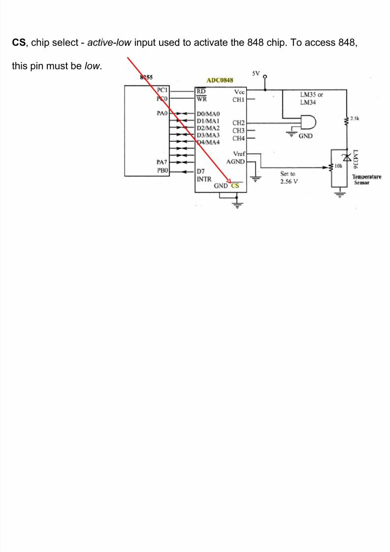
CS, chip select ! active-low input used to activate the %&% chip. To access %&%,
this pin must "e low .
8/16/2019 MMs Lect Ch-12 of 24Apr 14
http://slidepdf.com/reader/full/mms-lect-ch-12-of-24apr-14 6/31
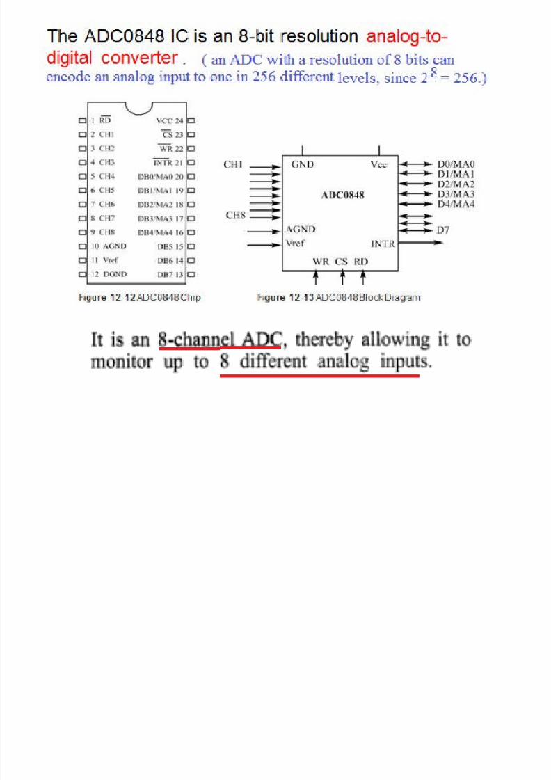
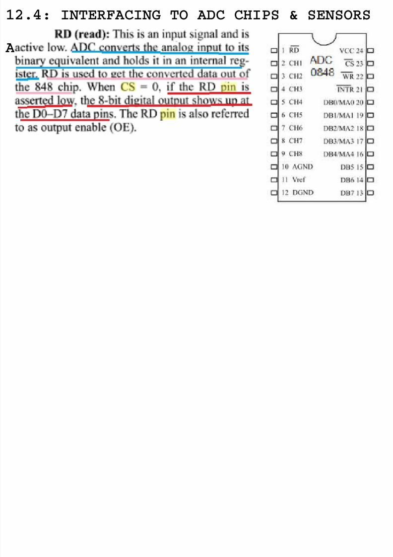
12.4: INTERFACING TO ADC CHIPS & SENSORS
ADC0848 chip pins
8/16/2019 MMs Lect Ch-12 of 24Apr 14
http://slidepdf.com/reader/full/mms-lect-ch-12-of-24apr-14 7/31
8/16/2019 MMs Lect Ch-12 of 24Apr 14
http://slidepdf.com/reader/full/mms-lect-ch-12-of-24apr-14 8/31
8/16/2019 MMs Lect Ch-12 of 24Apr 14
http://slidepdf.com/reader/full/mms-lect-ch-12-of-24apr-14 9/31
The x86 PC Assembly Language, Design, and Interfacing
By Muhammad Ali Mazidi, Janice Gillespie Mazidi and Danny Causey
© 2010, 2003, 2000, 1998 Peas!n "i#he $duca%i!n, &nc'
Peas!n Pen%ice "all ( )ppe *addle +ie, -J 0./8
8/16/2019 MMs Lect Ch-12 of 24Apr 14
http://slidepdf.com/reader/full/mms-lect-ch-12-of-24apr-14 10/31
8/16/2019 MMs Lect Ch-12 of 24Apr 14
http://slidepdf.com/reader/full/mms-lect-ch-12-of-24apr-14 11/31
8/16/2019 MMs Lect Ch-12 of 24Apr 14
http://slidepdf.com/reader/full/mms-lect-ch-12-of-24apr-14 12/31
8/16/2019 MMs Lect Ch-12 of 24Apr 14
http://slidepdf.com/reader/full/mms-lect-ch-12-of-24apr-14 13/31
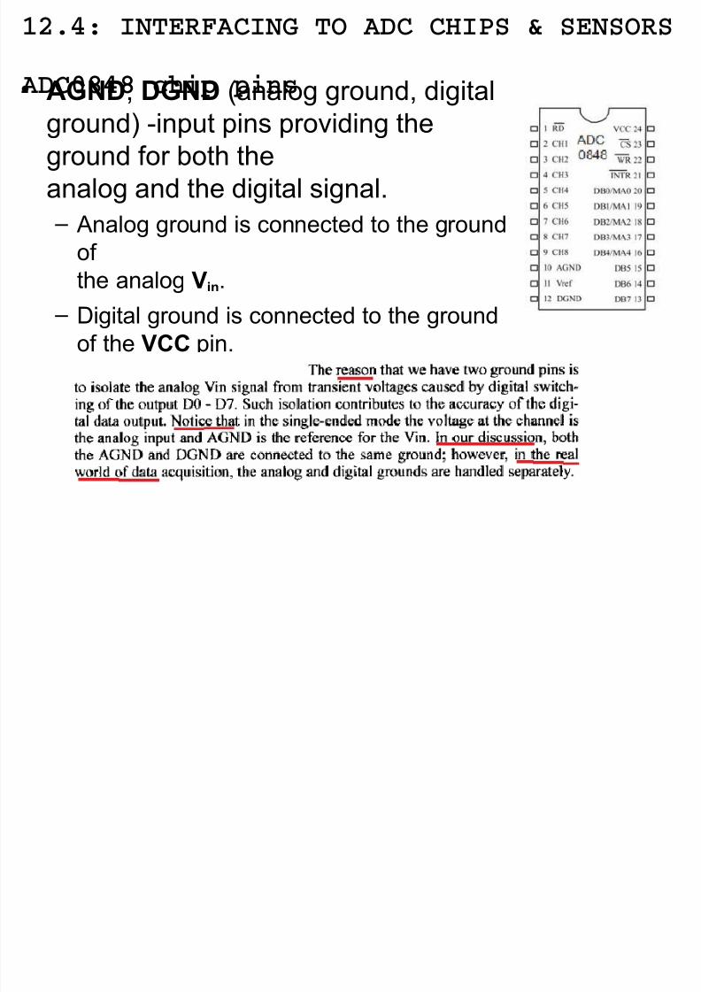
12.4: INTERFACING TO ADC CHIPS & SENSORS
ADC0848 chip pins• AGND, DGND (analog ground, digital
ground) !input pins providing theground for "oth the
analog and the digital signal.
– nalog ground is connected to the ground
of the analog Vin.
– Digital ground is connected to the ground
of the VCC pin.
8/16/2019 MMs Lect Ch-12 of 24Apr 14
http://slidepdf.com/reader/full/mms-lect-ch-12-of-24apr-14 14/31
12.4: INTERFACING TO ADC CHIPS & SENSORS
ADC0848 chip pins
Figure 12-14 'electing a $hannel and ead Timing for D$%&%
8/16/2019 MMs Lect Ch-12 of 24Apr 14
http://slidepdf.com/reader/full/mms-lect-ch-12-of-24apr-14 15/31
8/16/2019 MMs Lect Ch-12 of 24Apr 14
http://slidepdf.com/reader/full/mms-lect-ch-12-of-24apr-14 16/31
8/16/2019 MMs Lect Ch-12 of 24Apr 14
http://slidepdf.com/reader/full/mms-lect-ch-12-of-24apr-14 17/31
8/16/2019 MMs Lect Ch-12 of 24Apr 14
http://slidepdf.com/reader/full/mms-lect-ch-12-of-24apr-14 18/31
The x86 PC Assembly Language, Design, and Interfacing
By Muhammad Ali Mazidi, Janice Gillespie Mazidi and Danny Causey
© 2010, 2003, 2000, 1998 Peas!n "i#he $duca%i!n, &nc'
Peas!n Pen%ice "all ( )ppe *addle +ie, -J 0./8
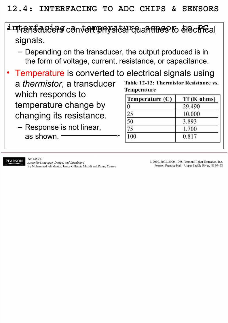
12.4: INTERFACING TO ADC CHIPS & SENSORS
interfacing a temperature sensor to PC • Transducers convert physical quantities to electrical
signals. – Depending on the transducer, the output produced is in
the form of voltage, current, resistance, or capacitance.
• Temperature is converted to electrical signals using
a thermistor , a transducer
which responds to
temperature change "y
changing its resistance. – esponse is not linear,
as shown.
8/16/2019 MMs Lect Ch-12 of 24Apr 14
http://slidepdf.com/reader/full/mms-lect-ch-12-of-24apr-14 19/31
The x86 PC Assembly Language, Design, and Interfacing
By Muhammad Ali Mazidi, Janice Gillespie Mazidi and Danny Causey
© 2010, 2003, 2000, 1998 Peas!n "i#he $duca%i!n, &nc'
Peas!n Pen%ice "all ( )ppe *addle +ie, -J 0./8
12.4: INTERFACING TO ADC CHIPS & SENSORS
interfacing a temperature sensor to PC • $omplexity with writing software for such nonlinear
devices has to the linear temperature sensor. – *ncluding the +-& and +- series from /ational
'emiconductor $orp.
8/16/2019 MMs Lect Ch-12 of 24Apr 14
http://slidepdf.com/reader/full/mms-lect-ch-12-of-24apr-14 20/31
The x86 PC Assembly Language, Design, and Interfacing
By Muhammad Ali Mazidi, Janice Gillespie Mazidi and Danny Causey
© 2010, 2003, 2000, 1998 Peas!n "i#he $duca%i!n, &nc'
Peas!n Pen%ice "all ( )ppe *addle +ie, -J 0./8
12.4: INTERFACING TO ADC CHIPS & SENSORS
LM34 and LM35 temperature sensors• +34 series sensors are precision integrated!circuit
temperature sensors with output voltage linearlyproportional to the Fahrenheit temperature.
– equires no external cali"ration, as it is inherently
cali"rated, outputting 0 m1 for each degree Fahrenheit .
8/16/2019 MMs Lect Ch-12 of 24Apr 14
http://slidepdf.com/reader/full/mms-lect-ch-12-of-24apr-14 21/31
The x86 PC Assembly Language, Design, and Interfacing
By Muhammad Ali Mazidi, Janice Gillespie Mazidi and Danny Causey
© 2010, 2003, 2000, 1998 Peas!n "i#he $duca%i!n, &nc'
Peas!n Pen%ice "all ( )ppe *addle +ie, -J 0./8
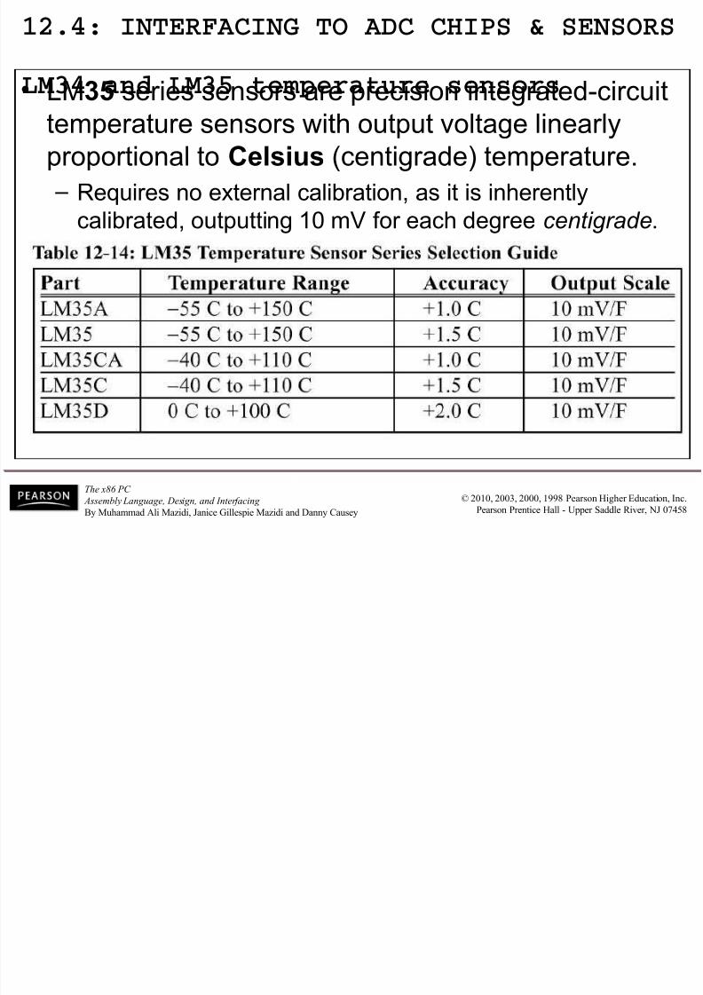
12.4: INTERFACING TO ADC CHIPS & SENSORS
LM34 and LM35 temperature sensors• +35 series sensors are precision integrated!circuit
temperature sensors with output voltage linearlyproportional to Celsius (centigrade) temperature.
– equires no external cali"ration, as it is inherently
cali"rated, outputting 0 m1 for each degree centigrade.
8/16/2019 MMs Lect Ch-12 of 24Apr 14
http://slidepdf.com/reader/full/mms-lect-ch-12-of-24apr-14 22/31
The x86 PC Assembly Language, Design, and Interfacing
By Muhammad Ali Mazidi, Janice Gillespie Mazidi and Danny Causey
© 2010, 2003, 2000, 1998 Peas!n "i#he $duca%i!n, &nc'
Peas!n Pen%ice "all ( )ppe *addle +ie, -J 0./8
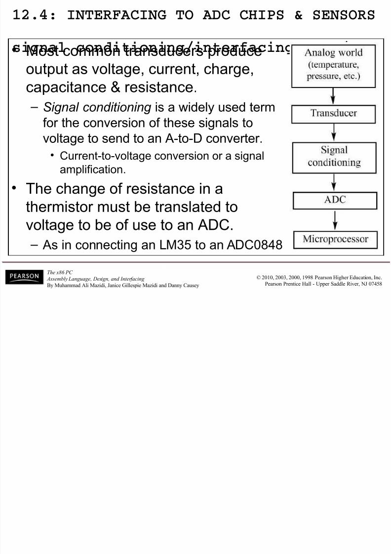
12.4: INTERFACING TO ADC CHIPS & SENSORS
signal conditioning/interfacing LM35/PC • ost common transducers produce
output as voltage, current, charge,capacitance 2 resistance.
– Signal conditioning is a widely used term
for the conversion of these signals to
voltage to send to an !to!D converter.• $urrent!to!voltage conversion or a signal
amplification.
• The change of resistance in a
thermistor must "e translated tovoltage to "e of use to an D$.
– s in connecting an +- to an D$%&%
8/16/2019 MMs Lect Ch-12 of 24Apr 14
http://slidepdf.com/reader/full/mms-lect-ch-12-of-24apr-14 23/31
The x86 PC Assembly Language, Design, and Interfacing
By Muhammad Ali Mazidi, Janice Gillespie Mazidi and Danny Causey
© 2010, 2003, 2000, 1998 Peas!n "i#he $duca%i!n, &nc'
Peas!n Pen%ice "all ( )ppe *addle +ie, -J 0./8
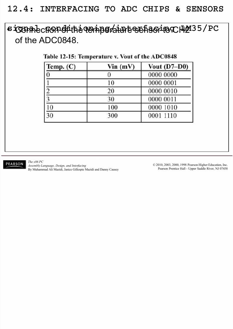
12.4: INTERFACING TO ADC CHIPS & SENSORS
signal conditioning/interfacing LM35/PC • $onnection of the temperature sensor to $34
of the D$%&%.
Figure 12-17 %4 $onnection to D$%&% and Temperature 'ensor
The +--5!4.
should overcome
fluctuations inthe power
supply.
The +--5!4.
6ener diode is
used to fix the
voltage across
the 07 #8T at4. volts.
8/16/2019 MMs Lect Ch-12 of 24Apr 14
http://slidepdf.com/reader/full/mms-lect-ch-12-of-24apr-14 24/31
The x86 PC Assembly Language, Design, and Interfacing
By Muhammad Ali Mazidi, Janice Gillespie Mazidi and Danny Causey
© 2010, 2003, 2000, 1998 Peas!n "i#he $duca%i!n, &nc'
Peas!n Pen%ice "all ( )ppe *addle +ie, -J 0./8
12.4: INTERFACING TO ADC CHIPS & SENSORS
signal conditioning/interfacing LM35/PC • $onnection of the temperature sensor to $34
of the D$%&%.
8/16/2019 MMs Lect Ch-12 of 24Apr 14
http://slidepdf.com/reader/full/mms-lect-ch-12-of-24apr-14 25/31
The x86 PC Assembly Language, Design, and Interfacing
By Muhammad Ali Mazidi, Janice Gillespie Mazidi and Danny Causey
© 2010, 2003, 2000, 1998 Peas!n "i#he $duca%i!n, &nc'
Peas!n Pen%ice "all ( )ppe *addle +ie, -J 0./8
Figure 12-18 D$ %%9%:
12.4: INTERFACING TO ADC CHIPS & SENSORS
ADC808/809• D$%%9%: has eight input channels.
– To convert % different analog inputs.• n %!"it D$.
8/16/2019 MMs Lect Ch-12 of 24Apr 14
http://slidepdf.com/reader/full/mms-lect-ch-12-of-24apr-14 26/31
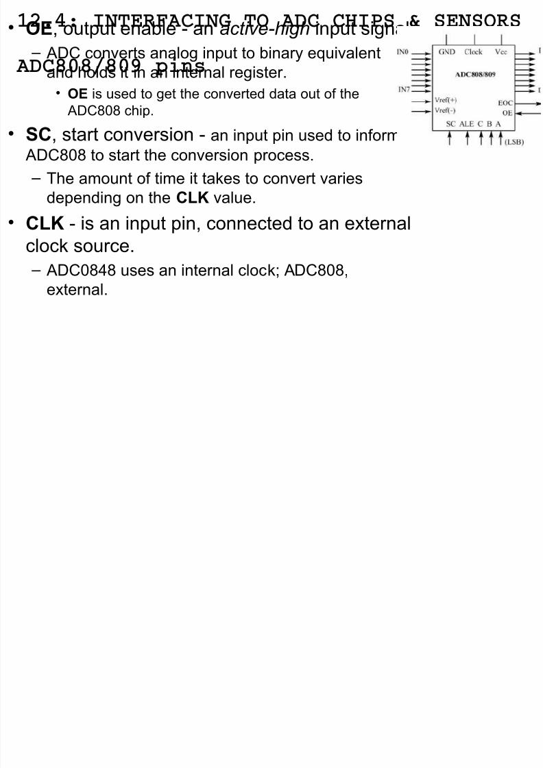
12.4: INTERFACING TO ADC CHIPS & SENSORS
ADC808/809 pins
• OE, output ena"le ! an active-high input signal.
– D$ converts analog input to "inary equivalent
and holds it in an internal register.
• OE is used to get the converted data out of the D$%% chip.
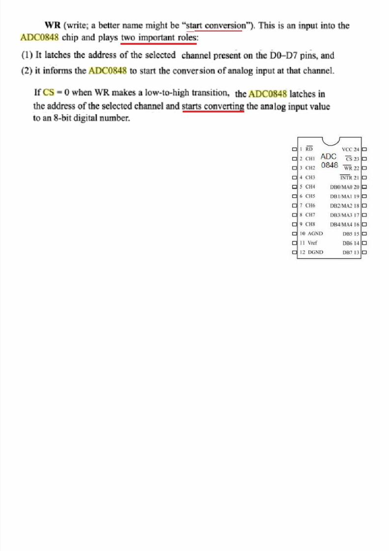
• SC, start conversion ! an input pin used to inform
D$%% to start the conversion process.
– The amount of time it ta7es to convert varies
depending on the CL value.
• CL ! is an input pin, connected to an external
cloc7 source.
– D$%&% uses an internal cloc7; D$%%,
external.
• EOC end of conversion an active low
8/16/2019 MMs Lect Ch-12 of 24Apr 14
http://slidepdf.com/reader/full/mms-lect-ch-12-of-24apr-14 27/31
12.4: INTERFACING TO ADC CHIPS & SENSORS
ADC808/809 pins
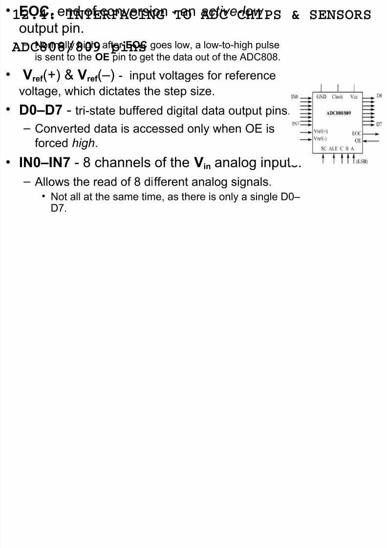
• EOC, end of conversion ! an active-low
output pin. – /ormally high, after EOC goes low, a low!to!high pulse
is sent to the OE pin to get the data out of the D$%%.
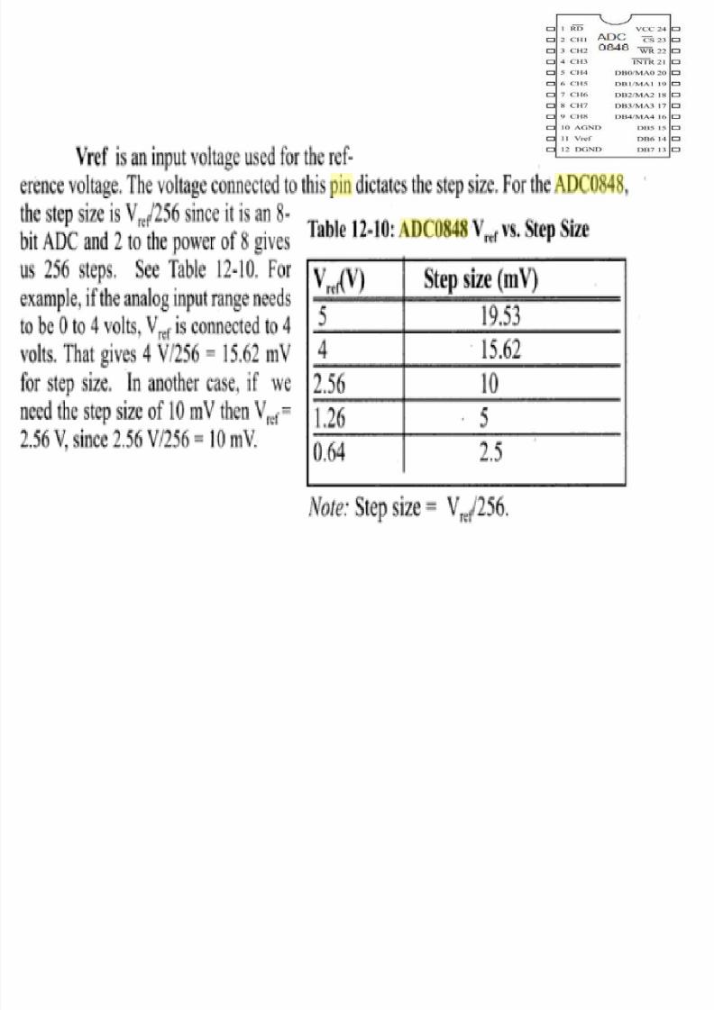
• Vre! (<) 2 Vre! (–) ! input voltages for reference
voltage, which dictates the step si6e.
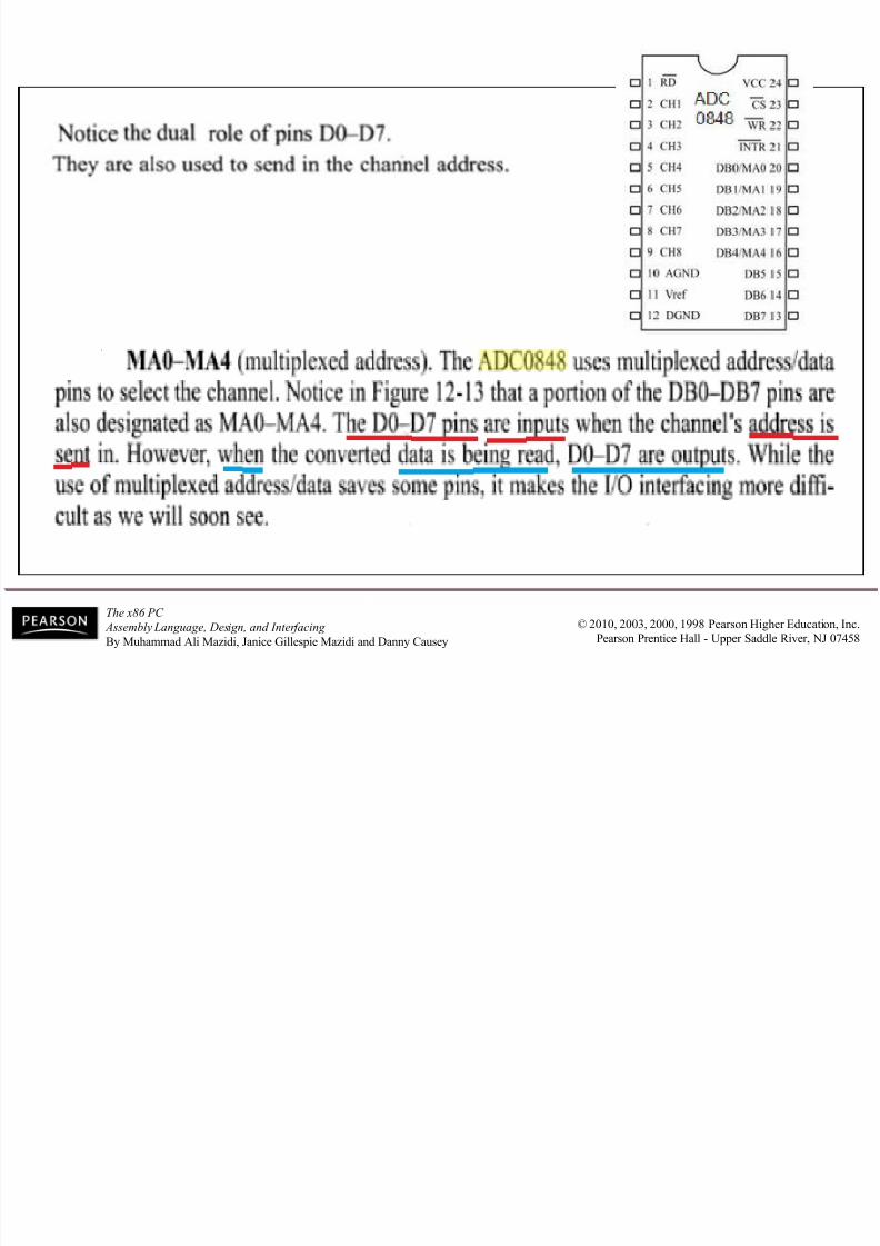
• D"#D7 ! tri!state "uffered digital data output pins.
– $onverted data is accessed only when 8= is
forced high.
• $N"#$N7 ! % channels of the Vin analog inputs.
– llows the read of % different analog signals.• /ot all at the same time, as there is only a single D–
D>.
8/16/2019 MMs Lect Ch-12 of 24Apr 14
http://slidepdf.com/reader/full/mms-lect-ch-12-of-24apr-14 28/31
12.4: INTERFACING TO ADC CHIPS & SENSORS
ADC808/809 pins
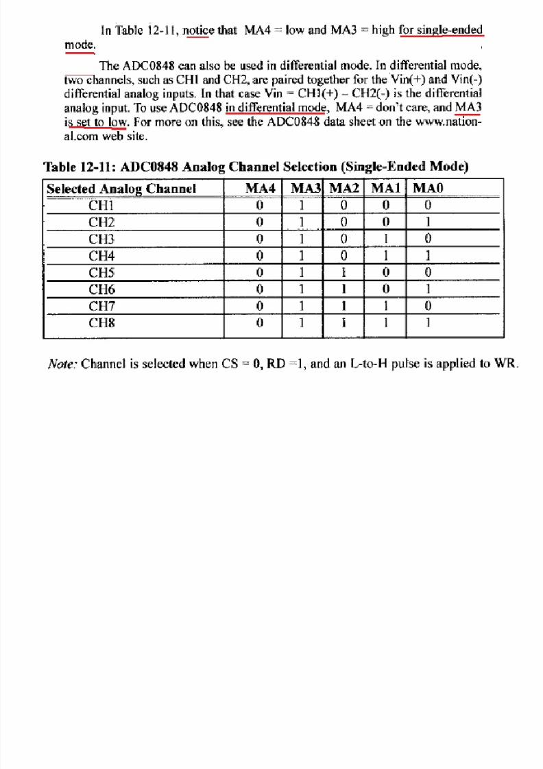
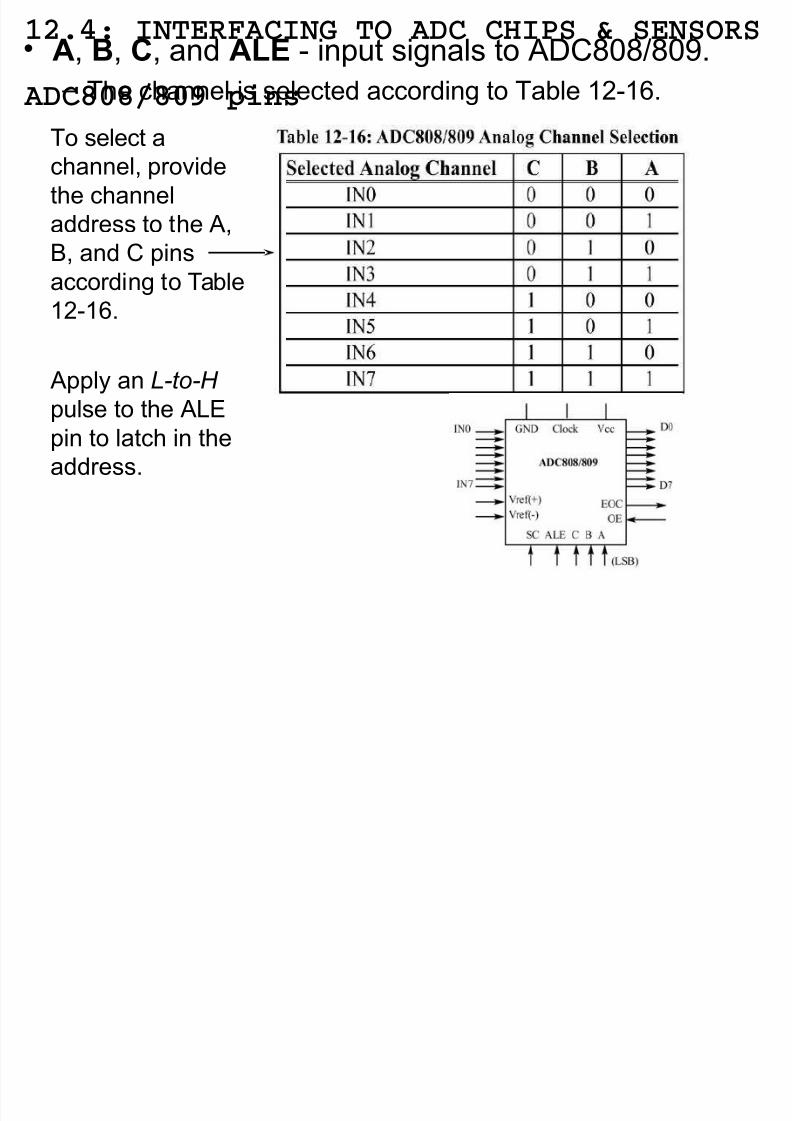
• A, %, C, and ALE ! input signals to D$%%9%:.
– The channel is selected according to Ta"le 04!05.
To select achannel, provide
the channel
address to the ,
?, and $ pins
according to Ta"le04!05.
pply an L-to-H
pulse to the +=pin to latch in the
address.
8/16/2019 MMs Lect Ch-12 of 24Apr 14
http://slidepdf.com/reader/full/mms-lect-ch-12-of-24apr-14 29/31
12.4: INTERFACING TO ADC CHIPS & SENSORS
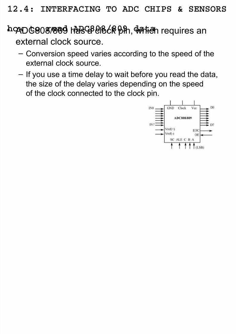
how to read ADC808/809 data• D$%%9%: has a cloc7 pin, which requires an
external cloc7 source. – $onversion speed varies according to the speed of the
external cloc7 source.
– *f you use a time delay to wait "efore you read the data,
the si6e of the delay varies depending on the speedof the cloc7 connected to the cloc7 pin.
12 4
8/16/2019 MMs Lect Ch-12 of 24Apr 14
http://slidepdf.com/reader/full/mms-lect-ch-12-of-24apr-14 30/31
The x86 PC Assembly Language, Design, and Interfacing
By Muhammad Ali Mazidi, Janice Gillespie Mazidi and Danny Causey
© 2010, 2003, 2000, 1998 Peas!n "i#he $duca%i!n, &nc'
Peas!n Pen%ice "all ( )ppe *addle +ie, -J 0./8
12.4: INTERFACING TO ADC CHIPS & SENSORS
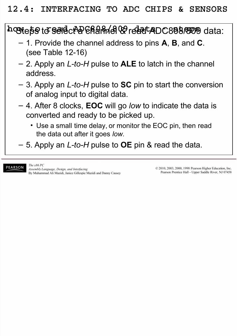
how to read ADC808/809 data - steps• 'teps to select a channel 2 read D$%%9%: data@
– 0. #rovide the channel address to pins A, %, and C.(see Ta"le 04!05)
– 4. pply an L-to-H pulse to ALE to latch in the channel
address.
– -. pply an L-to-H pulse to SC pin to start the conversionof analog input to digital data.
– &. fter % cloc7s, EOC will go low to indicate the data is
converted and ready to "e pic7ed up.
• Ase a small time delay, or monitor the =8$ pin, then readthe data out after it goes low .
– . pply an L-to-H pulse to OE pin 2 read the data.
i
8/16/2019 MMs Lect Ch-12 of 24Apr 14
http://slidepdf.com/reader/full/mms-lect-ch-12-of-24apr-14 31/31
The x86 PC
Assembly Language, Design, and Interfacing © 2010, 2003, 2000, 1998 Peas!n "i#he $duca%i!n, &nc'
ENDS ; TWELVE
Dec Hex Bin
12 C 00001100