60
QD5 Quik-Drive voltage regulator tap-changer manual COOPER POWER SERIES Voltage Regulators MN225012EN Effective March 2016 Supersedes S225-12-2 February 2013

QD5 Quik-Drive voltage regulator tap-changer manual
COOPER POWERSERIES
Voltage Regulators MN225012EN
Effective March 2016Supersedes S225-12-2 February 2013

ii QD5 QUIK-DRIVE TAP-CHANGER INSTALLATION AND MAINTENANCE INSTRUCTIONS MN225012EN March 2016
DISCLAIMER OF WARRANTIES AND LIMITATION OF LIABILITY
The information, recommendations, descriptions and safety notations in this document are based on Eaton Corporation’s (“Eaton”) experience and judgment and may not cover all contingencies. If further information is required, an Eaton sales office should be consulted. Sale of the product shown in this literature is subject to the terms and conditions outlined in appropriate Eaton selling policies or other contractual agreement between Eaton and the purchaser.
THERE ARE NO UNDERSTANDINGS, AGREEMENTS, WARRANTIES, EXPRESSED OR IMPLIED, INCLUDING WARRANTIES OF FITNESS FOR A PARTICULAR PURPOSE OR MERCHANTABILITY, OTHER THAN THOSE SPECIFICALLY SET OUT IN ANY EXISTING CONTRACT BETWEEN THE PARTIES. ANY SUCH CONTRACT STATES THE ENTIRE OBLIGATION OF EATON. THE CONTENTS OF THIS DOCUMENT SHALL NOT BECOME PART OF OR MODIFY ANY CONTRACT BETWEEN THE PARTIES.
In no event will Eaton be responsible to the purchaser or user in contract, in tort (including negligence), strict liability or other-wise for any special, indirect, incidental or consequential damage or loss whatsoever, including but not limited to damage or loss of use of equipment, plant or power system, cost of capital, loss of power, additional expenses in the use of existing power facilities, or claims against the purchaser or user by its customers resulting from the use of the information, recommendations and descriptions contained herein. The information contained in this manual is subject to change without notice.
iiiQD5 QUIK-DRIVE TAP-CHANGER INSTALLATION AND MAINTENANCE INSTRUCTIONS MN225012EN March 2016
Contents
SAFETY INFORMATIONSafety information . . . . . . . . . . . . . . . . . . . . . . . . . . . . . . . . . . . . . . . . . . . . . . . . . . . . . . . . . . . . . . . . . . . . . . . . . . . . . iv
PRODUCT INFORMATIONIntroduction . . . . . . . . . . . . . . . . . . . . . . . . . . . . . . . . . . . . . . . . . . . . . . . . . . . . . . . . . . . . . . . . . . . . . . . . . . . . . . . . . . .1
Standards . . . . . . . . . . . . . . . . . . . . . . . . . . . . . . . . . . . . . . . . . . . . . . . . . . . . . . . . . . . . . . . . . . . . . . . . . . . . . . . . . . . . .1
General . . . . . . . . . . . . . . . . . . . . . . . . . . . . . . . . . . . . . . . . . . . . . . . . . . . . . . . . . . . . . . . . . . . . . . . . . . . . . . . . . . . . . . .1
Motor . . . . . . . . . . . . . . . . . . . . . . . . . . . . . . . . . . . . . . . . . . . . . . . . . . . . . . . . . . . . . . . . . . . . . . . . . . . . . . . . . . . . . . . .1
Motor resistance . . . . . . . . . . . . . . . . . . . . . . . . . . . . . . . . . . . . . . . . . . . . . . . . . . . . . . . . . . . . . . . . . . . . . . . . . . . . . . .1
Motor capacitor . . . . . . . . . . . . . . . . . . . . . . . . . . . . . . . . . . . . . . . . . . . . . . . . . . . . . . . . . . . . . . . . . . . . . . . . . . . . . . . .2
Holding switch . . . . . . . . . . . . . . . . . . . . . . . . . . . . . . . . . . . . . . . . . . . . . . . . . . . . . . . . . . . . . . . . . . . . . . . . . . . . . . . . .2
Contacts . . . . . . . . . . . . . . . . . . . . . . . . . . . . . . . . . . . . . . . . . . . . . . . . . . . . . . . . . . . . . . . . . . . . . . . . . . . . . . . . . . . . . .3
Main stationary contacts . . . . . . . . . . . . . . . . . . . . . . . . . . . . . . . . . . . . . . . . . . . . . . . . . . . . . . . . . . . . . . . . . . . . . . . . .3
Main movable contacts . . . . . . . . . . . . . . . . . . . . . . . . . . . . . . . . . . . . . . . . . . . . . . . . . . . . . . . . . . . . . . . . . . . . . . . . . .3
Reversing stationary contacts . . . . . . . . . . . . . . . . . . . . . . . . . . . . . . . . . . . . . . . . . . . . . . . . . . . . . . . . . . . . . . . . . . . . .3
Main reversing movable contacts . . . . . . . . . . . . . . . . . . . . . . . . . . . . . . . . . . . . . . . . . . . . . . . . . . . . . . . . . . . . . . . . . .4
Micro switches . . . . . . . . . . . . . . . . . . . . . . . . . . . . . . . . . . . . . . . . . . . . . . . . . . . . . . . . . . . . . . . . . . . . . . . . . . . . . . . . .4
QD5 tap-changer operating sequence . . . . . . . . . . . . . . . . . . . . . . . . . . . . . . . . . . . . . . . . . . . . . . . . . . . . . . . . . . . . . . .4
MAINTENANCE, SERVICE AND TROUBLESHOOTING . . . . . . . . . . . . . . . . . . . . . . . . . . . . . . . . . . . . . . . . . . . . . . . . .5
QD5 TAP-CHANGER SCHEMATIC . . . . . . . . . . . . . . . . . . . . . . . . . . . . . . . . . . . . . . . . . . . . . . . . . . . . . . . . . . . . . . . . . . .10
QD5 TAP-CHANGER TORQUE REGUIREMENTS. . . . . . . . . . . . . . . . . . . . . . . . . . . . . . . . . . . . . . . . . . . . . . . . . . . . . . .13
QD5 TAP-CHANGER REVERSING MOVABLE CONTACT ASSEMBLY KIT 5740785B72ER . . . . . . . . . . . . . . . . .19
QD5 TAP-CHANGER REVERSING NEUTRAL STATIONARY CONTACT ASSEMBLY KIT 5791646A26 . . . . . . 23
QD5 TAP-CHANGER MAIN STATIONARY CONTACT ASSEMBLY KIT 5791646A24 . . . . . . . . . . . . . . . . . . . . . . .30
QD5 TAP-CHANGER VL REVERSING STATIONARY CONTACT ASSEMBLY KIT 5791646A25 . . . . . . . . . . . . . .33
QD5 TAP-CHANGE VR REVERSING STATIONARY CONTACT ASSEMBLY KIT 5791646A27 . . . . . . . . . . . . . . .36
QD5 TAP-CHANGER MOTOR REPLACEMENT PROCEDURE KIT 57A63675100A . . . . . . . . . . . . . . . . . . . . . . . . .39
QD5 TAP-CHANGER MAIN MOVABLE CONTACT REPLACEMENT KIT 5740785B33 . . . . . . . . . . . . . . . . . . . . . .46

iv QD5 QUIK-DRIVE TAP-CHANGER INSTALLATION AND MAINTENANCE INSTRUCTIONS MN225012EN March 2016
The instructions in this manual are not intended as a substitute for proper training or adequate experience in the safe operation of the equipment described. Only competent technicians who are familiar with this equipment should install, operate, and service it.
A competent technician has these qualifications:
• Is thoroughly familiar with these instructions.
• Is trained in industry-accepted high and low-voltage safe operating practices and procedures.
• Is trained and authorized to energize, de-energize, clear, and ground power distribution equipment.
• Is trained in the care and use of protective equipment such as arc flash clothing, safety glasses, face shield, hard hat, rubber gloves, clampstick, hotstick, etc.
Following is important safety information. For safe installation and operation of this equipment, be sure to read and understand all cautions and warnings.
Safety instructionsFollowing are general caution and warning statements that apply to this equipment. Additional statements, related to specific tasks and procedures, are located throughout the manual.
Safety for life!
SAFETYFOR LIFE
!SAFETYFOR LIFE
Eaton meets or exceeds all applicable industry standards relating to product safety in its Cooper Power™ series products. We actively promote safe practices in the use and maintenance of our products through our service literature, instructional training programs, and the continuous efforts of all Eaton employees involved in product design, manufacture, marketing, and service.
We strongly urge that you always follow all locally approved safety procedures and safety instructions when working around high voltage lines and equipment, and support our “Safety For Life” mission.
Safety information
DANGERHazardous voltage. Contact with hazardous voltage will cause death or severe personal injury. Follow all locally approved safety procedures when working around high- and low-voltage lines and equipment. G103.3
WARNING Before installing, operating, maintaining, or testing this equipment, carefully read and understand the contents of this manual. Improper operation, handling or maintenance can result in death, severe personal injury, and equipment damage. G101.0
WARNING This equipment is not intended to protect human life. Follow all locally approved procedures and safety practices when installing or operating this equipment. Failure to comply can result in death, severe personal injury and equipment damage. G102.1
WARNING Power distribution and transmission equipment must be properly selected for the intended application. It must be installed and serviced by competent personnel who have been trained and understand proper safety procedures. These instructions are written for such personnel and are not a substitute for adequate training and experience in safety procedures. Failure to properly select, install or maintain power distribution and transmission equipment can result in death, severe personal injury, and equipment damage. G122.3
This manual may contain four types of hazard statements:
DANGER Indicates an imminently hazardous situation which, if not avoided, will result in death or serious injury.
WARNING Indicates a potentially hazardous situation which, if not avoided, could result in death or serious injury.
CAUTION Indicates a potentially hazardous situation which, if not avoided, may result in minor or moderate injury.
CAUTION Indicates a potentially hazardous situation which, if not avoided, may result in equipment damage only.
Hazard Statement Definitions
Product information
IntroductionEaton combines more than 50 years of tap-changer experience with the latest technology providing the most advanced and reliable voltage regulator tap-changer in its Cooper Power series QD5 Quik-Drive™ tap-changer. Eaton provides the proven value customers have come to expect from the leader. By using advanced thermal-set material rather than Phenolic material Eaton has been able to design in strength to meet the most demanding applications. The design provides for an improved contact alignment and longer contact life. The QD5 tap-changer incorporates Cooper’s exclusive holding switch circuit, which has set the standard for tap-changer tracking reliability.
The QD5 Quik-Drive tap-changer offers many advanced features when integrated with Eaton's Cooper Power series voltage regulator controls. Applications such as Preventative Maintenances Tapping (PMT™), Duty Cycle Monitor (DCM), and Time–ON-TAP™ features enables the unique capability to monitoring factors that affect tap-changer life.
Read this manual firstThese instructions apply to distribution voltage regulators equipped with the QD5 tap-changer. Read these instructions carefully before attempting maintenance on the voltage regulator.
The equipment covered by these instructions should be operated and serviced only by competent personnel familiar with good safety practices. These instructions are written for such personnel and are not intended as a substitute for adequate training and experience in safe procedures for this type of equipment.
The text of this instruction includes information concerning hazards to safety, which are common to all regulators. This safety hazard information is offered for guidance when installing and operating the descriptive matter to aid in preventing damage to the equipment and to advise of possible hazards to personnel. When reading this text, the meaning and content of these statements should be understood and followed carefully.
StandardsISO 9001 Certified Quality Management System
GeneralService Information MN225012EN covers operating, maintenance and component replacement instructions for the QD5 Quik-Drive tap-changer in Eaton's Cooper Power series VR-32 voltage regulators. The QD5 tap-changer in 2003 replaced the 770 Direct Drive tap-changers for low current application single-phase voltage regulators. Replacing the medium direct drive model 770, 150 kV BIL, the QD5 tap-changer like the 770 direct drive tap-changer are used on voltage regulators with a load rating up to 328 Amps. In 2007, the original Phenolic contact board design of the QD5 was replace by thermal-set material.
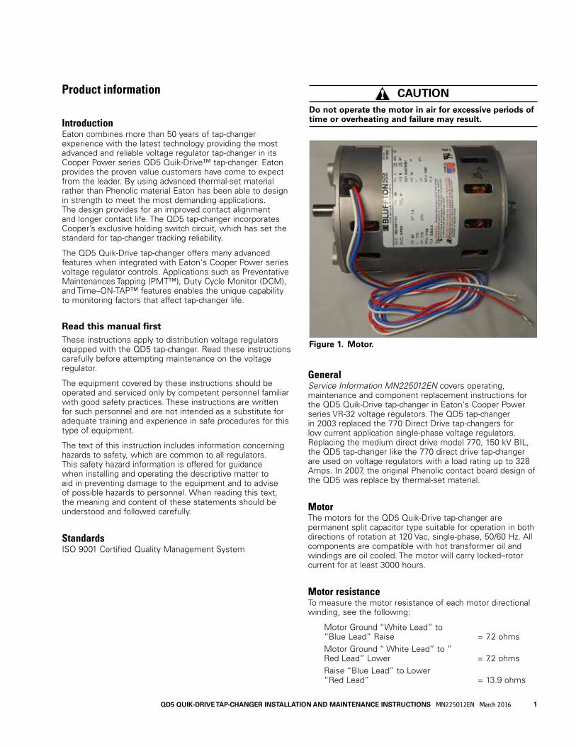
MotorThe motors for the QD5 Quik-Drive tap-changer are permanent split capacitor type suitable for operation in both directions of rotation at 120 Vac, single-phase, 50/60 Hz. All components are compatible with hot transformer oil and windings are oil cooled. The motor will carry locked–rotor current for at least 3000 hours.
Motor resistanceTo measure the motor resistance of each motor directional winding, see the following:
Motor Ground “White Lead” to “Blue Lead” Raise = 7.2 ohms Motor Ground “ White Lead” to ” Red Lead” Lower = 7.2 ohms Raise “Blue Lead” to Lower “Red Lead” = 13.9 ohms
Figure 1. Motor.
1QD5 QUIK-DRIVE TAP-CHANGER INSTALLATION AND MAINTENANCE INSTRUCTIONS MN225012EN March 2016
CAUTION Do not operate the motor in air for excessive periods of time or overheating and failure may result.

Holding switchEaton's tap-changers are equipped with a holding switch to assure that a tap-changer operation is completed. This switch also provides a repetitive and accurate opening action causing the motor to stop the drive components with correct alignment. A signal from the holding switch activates the operations counter and prevents time delay reset during a tap change. The holding switch is operated by a pinion cam causing the holding switch lever to close in on either the raise or lower micro switch.
If there is a problem with one of the micro switches on the holding switch, the individual micro switch should not be replaced. Instead, the complete holding-switch assembly must be replaced. Replacement of an individual micro switch can cause alignment problems which will affect the operation of the tap-changer. Special fixtures are used to assemble the holding-switch assembly to ensure that alignment gap setting requirements are met.
Motor capacitorThe QD5 tap-changer motor uses a 50 μF, 440 Vac, and 100°C motor capacitor. The motor capacitor is not part of the tap-changer assembly; it will be located in the voltage regulator control box.
Motor capacitorSize Rating
50 μF, 440 Vac, 100°C for 50 and 60 Hertz
It is recommended that a replacement capacitor be of the same size and rating as was originally supplied with the unit. Incorrectly sized motor capacitors can cause the motor to labor and not run properly or at all; premature motor failure will result. Tap position tracking of the voltage regulator control will also be adversely affected by improperly sized motor capacitors.
Figure 2. Motor capacitor.
Figure 3. Holding switch assembly.
2 QD5 QUIK-DRIVE TAP-CHANGER INSTALLATION AND MAINTENANCE INSTRUCTIONS MN225012EN March 2016
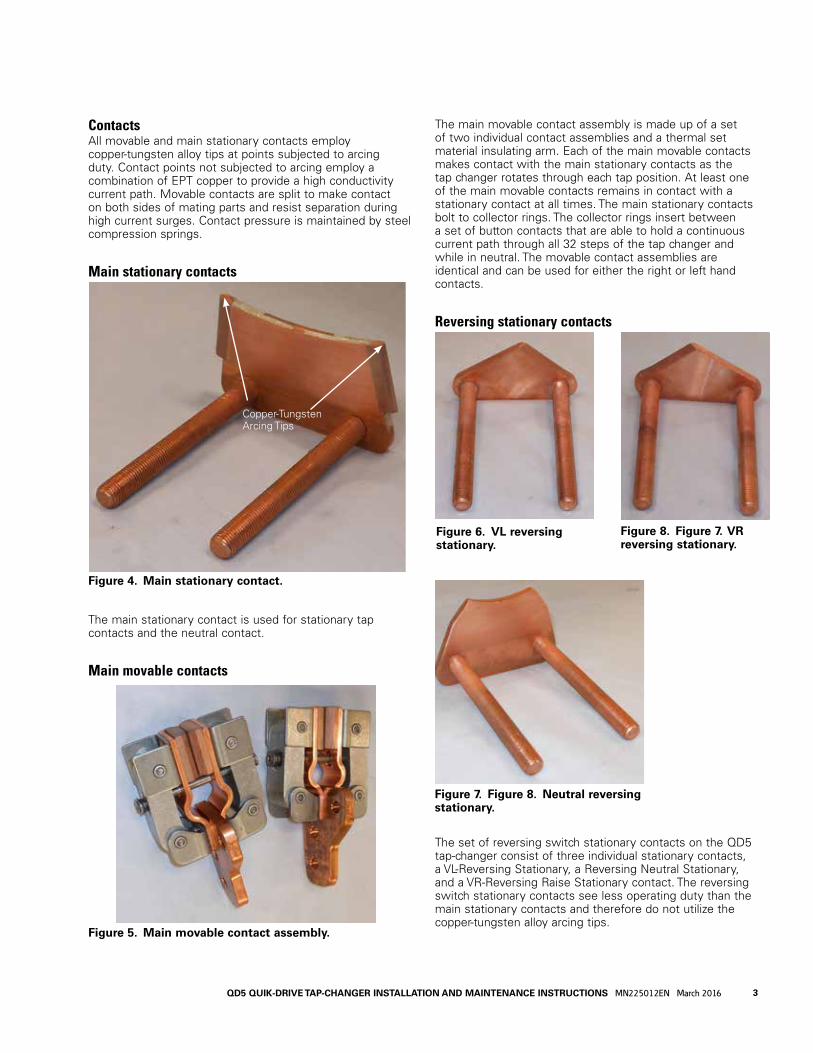
ContactsAll movable and main stationary contacts employ copper-tungsten alloy tips at points subjected to arcing duty. Contact points not subjected to arcing employ a combination of EPT copper to provide a high conductivity current path. Movable contacts are split to make contact on both sides of mating parts and resist separation during high current surges. Contact pressure is maintained by steel compression springs.
Main stationary contacts
The main stationary contact is used for stationary tap contacts and the neutral contact.
Main movable contacts
The main movable contact assembly is made up of a set of two individual contact assemblies and a thermal set material insulating arm. Each of the main movable contacts makes contact with the main stationary contacts as the tap changer rotates through each tap position. At least one of the main movable contacts remains in contact with a stationary contact at all times. The main stationary contacts bolt to collector rings. The collector rings insert between a set of button contacts that are able to hold a continuous current path through all 32 steps of the tap changer and while in neutral. The movable contact assemblies are identical and can be used for either the right or left hand contacts.
Reversing stationary contacts
The set of reversing switch stationary contacts on the QD5 tap-changer consist of three individual stationary contacts, a VL-Reversing Stationary, a Reversing Neutral Stationary, and a VR-Reversing Raise Stationary contact. The reversing switch stationary contacts see less operating duty than the main stationary contacts and therefore do not utilize the copper-tungsten alloy arcing tips.
Figure 5. Main movable contact assembly.
Figure 6. VL reversing stationary.
Figure 7. Figure 8. Neutral reversing stationary.
Figure 8. Figure 7. VR reversing stationary.
Figure 4. Main stationary contact.
Copper-Tungsten Arcing Tips
3QD5 QUIK-DRIVE TAP-CHANGER INSTALLATION AND MAINTENANCE INSTRUCTIONS MN225012EN March 2016

Main reversing movable contacts
The reversing switch changes the polarity of the tapped winding. When the QD5 Quik-Drive tap-changer is in neutral position, the reversing switch is located on the “VN” Reversing Neutral Stationary Contact. In the open position the reversing switch is not in the load current circuit.
The reversing switch motion on the QD5 tap-changer occurs as the main movable contacts enter or leave the neutral position. The QD5 tap-changer reversing switch movable contacts interact with the three reversing stationary contacts during the buck and boost operation of the tap changer.
The first tap step in either direction rotates the Reversing Segment actuator causing the Reversing Segment Actuator arms to rotate the reversing switch and engage the appropriate reversing stationary contact. When the tap-changer receives a signal for raise and the reversing switch contact is in neutral, the reversing movable contacts will move clockwise on to the VR stationary bridging the VR and VN stationary contacts. In the lower direction from neutral the reversing movable will move counter clockwise on to the VL stationary contact. The reversing movable will be bridging the VL and VN when moving in the lower direction.
Micro switchesMicro switches are use for the holding switch, reversing logic, neutral indication and taping limit logic switches.
Two sets of normally closed switches are use to provide a safety switch circuit to prevent the tap-changer from tapping beyond 16R and 16L acting as a fail-safe to the mechanical stop. The switches enable the tap changer to step back from the mechanical stop when the holding switch is closed.
The micro switches used are rated for –40°C to 130°C, 5 Amp 125/250 Vac rating. The switches are designed to exceed one million operations at QD5 tap-changer current.
QD5 tap-changer operating sequenceWhen the tap-changer is in the neutral position and the control calls for a tap change, the following events occur:
1. Motor will start and drive the chain sprocket.
2. Rotation of the chain sprocket rotates the drive pinion.
3. The drive pinion cam engages and closes in the holding switch.
4. Drive pinion roller engages the position indicator drive gear advancing the position indicator pointer.
5. The sprocket drive roller engages the Geneva gear rotating the Geneva gear.
6. As the sprocket rotates and the holding switch is actuated, the sprocket cam dis-engages and releases the brake.
7. The rotation of the Geneva gear causes the reversing segment actuator to operate which moves the reversing switch movable contacts, via the linkage tying the reversing segment actuator to the reversing switch from neutral to VR or VL.
8. Rotation of the Geneva gear relocates the movable contacts on the stationary contacts.
9. Drive pinion cam returns to the open area opening the holding switch.
10. Tap Change is completed.
Figure 9. Reversing movable contact assembly.
4 QD5 QUIK-DRIVE TAP-CHANGER INSTALLATION AND MAINTENANCE INSTRUCTIONS MN225012EN March 2016
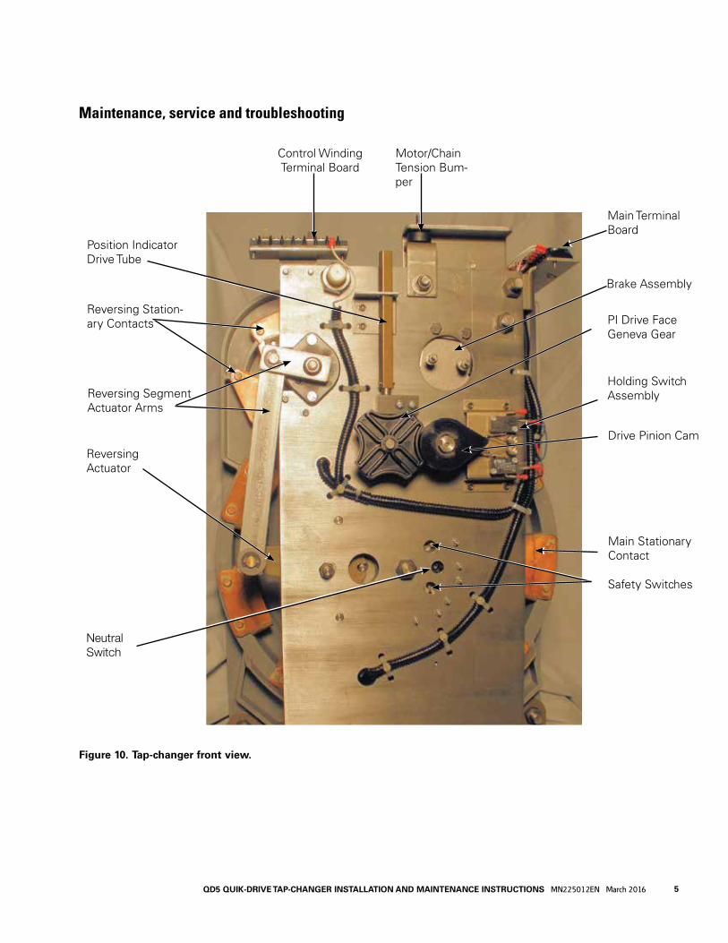
Maintenance, service and troubleshooting
Position Indicator Drive Tube
Reversing Station-ary Contacts
Reversing Segment Actuator Arms
Reversing Actuator
Figure 10. Tap-changer front view.
Control Winding Terminal Board
Holding Switch Assembly
Drive Pinion Cam
Main Stationary Contact
Safety Switches
PI Drive Face Geneva Gear
Brake Assembly
Main Terminal Board
Motor/Chain Tension Bum-per
Neutral Switch
5QD5 QUIK-DRIVE TAP-CHANGER INSTALLATION AND MAINTENANCE INSTRUCTIONS MN225012EN March 2016

Figure 11. Back side of QD5 tap-changer.
#7 Stationary
#6 Stationary
#5 Stationary
#3 Stationary
#2 Stationary
#1 Main Stationary Contact
VL-Reversing Stationary Contact
Neutral Stationary
VR-Reversing Stationary Contact#8 Stationary
#4 Stationary
Reversing Neutral Stationary Contact
6 QD5 QUIK-DRIVE TAP-CHANGER INSTALLATION AND MAINTENANCE INSTRUCTIONS MN225012EN March 2016

Figure 12. Inside drive frame.
Motor
Brake Assembly
Raise Safety Switch
Neutral Switch
Lower Safety Switch
Reversing Segment Actuator
Drive Sprocket Gear
Logic Switches
Chain
7QD5 QUIK-DRIVE TAP-CHANGER INSTALLATION AND MAINTENANCE INSTRUCTIONS MN225012EN March 2016
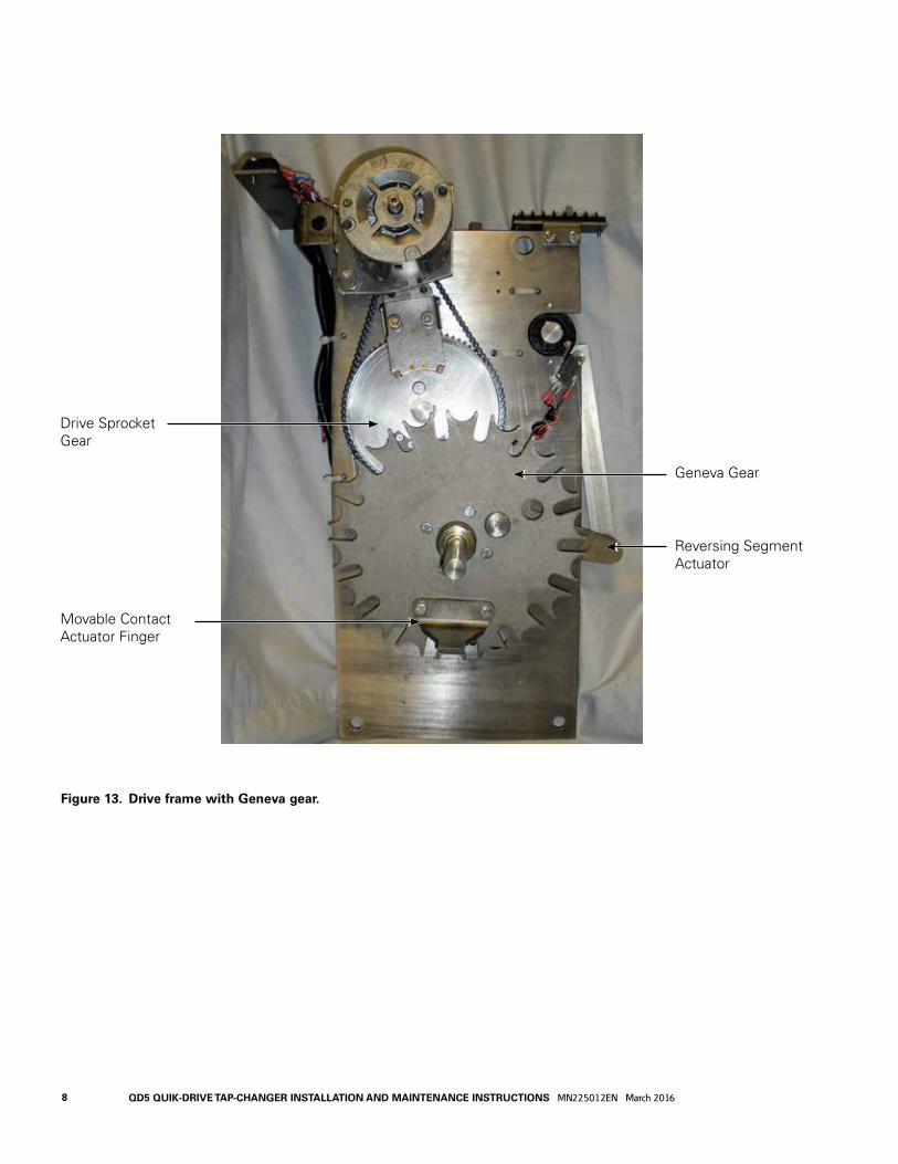
Figure 13. Drive frame with Geneva gear.
Geneva Gear
Reversing Segment Actuator
Movable Contact Actuator Finger
Drive Sprocket Gear
8 QD5 QUIK-DRIVE TAP-CHANGER INSTALLATION AND MAINTENANCE INSTRUCTIONS MN225012EN March 2016
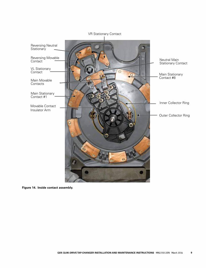
Figure 14. Inside contact assembly.
Reversing Neutral Stationary
Reversing Movable Contact
VL Stationary Contact
Main Movable Contacts
Main Stationary Contact #1
Movable Contact Insulator Arm
VR Stationary Contact
Neutral Main Stationary Contact
Main Stationary Contact #8
Inner Collector Ring
Outer Collector Ring
9QD5 QUIK-DRIVE TAP-CHANGER INSTALLATION AND MAINTENANCE INSTRUCTIONS MN225012EN March 2016
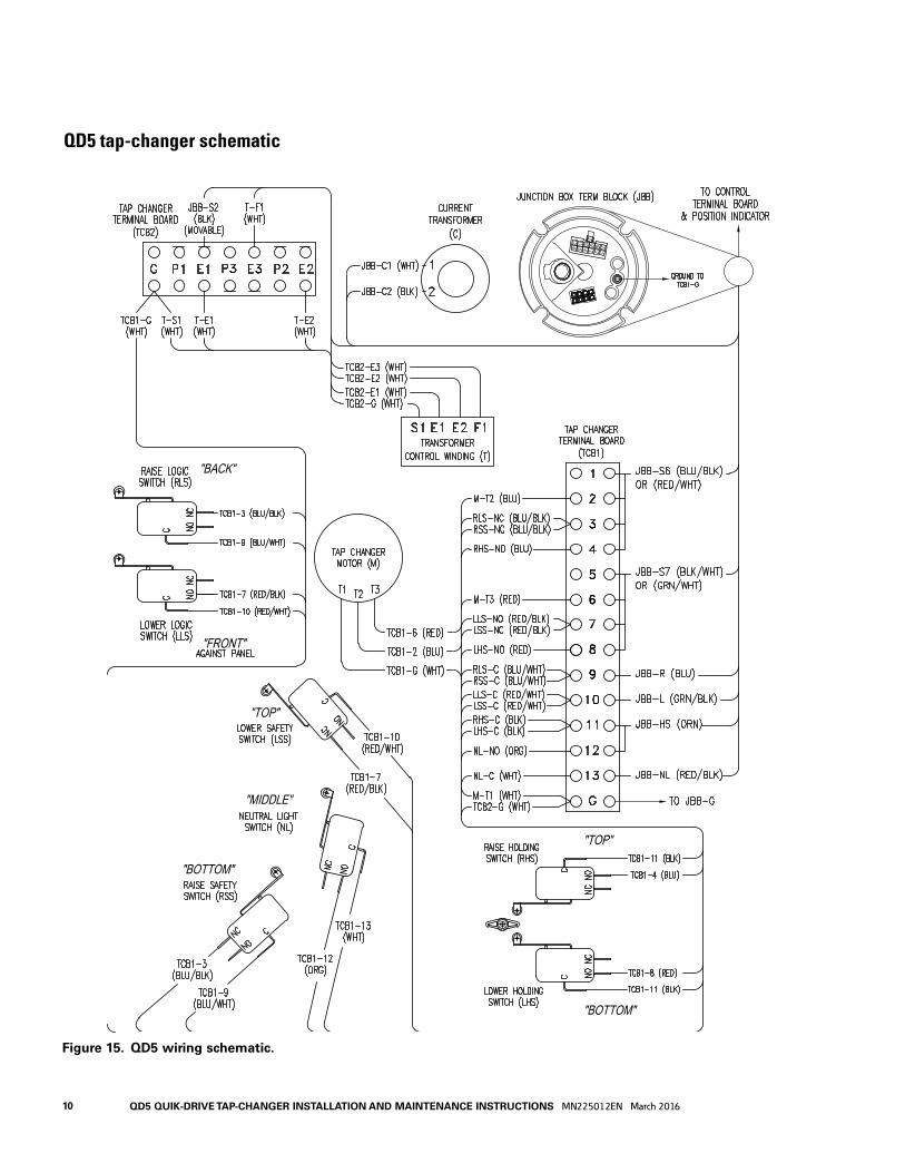
QD5 tap-changer schematic
Figure 15. QD5 wiring schematic.
10 QD5 QUIK-DRIVE TAP-CHANGER INSTALLATION AND MAINTENANCE INSTRUCTIONS MN225012EN March 2016
MOVEABLE ARCING
CONTACT
MOVEABLE ARCING
CONTACT
NEW CONTACTS
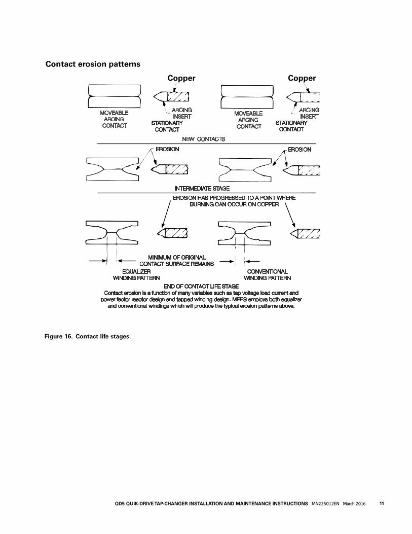
END OF CONTACT LIFE STAGEContact erosion is a function of many variables such as tap voltage load current and
power factor reactor design and tapped winding design. MEPS employs both equalizerand conventional windings which will produce the typical erosion patterns above.
INTERMEDIATE STAGE
STATIONARYCONTACT
STATIONARYCONTACT
EROSION EROSION
NEW CONTACTS
ARCINGINSERT
ARCINGINSERT
EROSION HAS PROGRESSED TO A POINT WHEREBURNING CAN OCCUR ON COPPER
CONVENTIONAL WINDING PATTERN
EQUALIZERWINDING PATTERN
MINIMUM OF ORIGINALCONTACT SURFACE REMAINS
Figure 16. Contact life stages.
Contact erosion patterns
Copper Copper
11QD5 QUIK-DRIVE TAP-CHANGER INSTALLATION AND MAINTENANCE INSTRUCTIONS MN225012EN March 2016
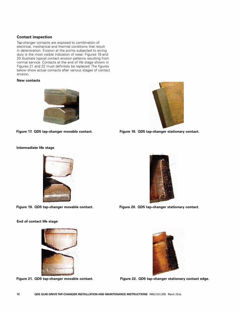
Contact inspectionTap-changer contacts are exposed to combination of electrical, mechanical and thermal conditions that result in deterioration. Erosion at the points subjected to arcing duty is the most visible indication of wear. Figures 19 and 20 illustrate typical contact erosion patterns resulting from normal service. Contacts at the end of life stage shown in Figures 21 and 22 must definitely be replaced. The figures below show actual contacts after various stages of contact erosion.
New contacts
Figure 17. QD5 tap-changer movable contact. Figure 18. QD5 tap-changer stationary contact.
Figure 19. QD5 tap-changer movable contact. Figure 20. QD5 tap-changer stationary contact.
Intermediate life stage
Figure 21. QD5 tap-changer movable contact. Figure 22. QD5 tap-changer stationary contact edge.
End of contact life stage
12 QD5 QUIK-DRIVE TAP-CHANGER INSTALLATION AND MAINTENANCE INSTRUCTIONS MN225012EN March 2016

QD5 tap-changer torque requirements
Figure 23. QD5 tap-changer stationary contact torque requirements.
Figure 24. Front drive torque requirements.
30–40 in-lbs(3.4–4.5 Nm)
4–5 in-lbs(0.5–0.6 Nm)
180–192 in-lbs(20.3–21.6 Nm)
12–18 in-lbs(1.4–2.0 Nm)
Stationary Contact
Reversing Stationary Contact
80–90 in-lbs(9.0–10.2 Nm)
13QD5 QUIK-DRIVE TAP-CHANGER INSTALLATION AND MAINTENANCE INSTRUCTIONS MN225012EN March 2016

Figure 25. Motor to mounting bracket torque requirements.
Figure 26. Motor pivot stud and locknut torque requirements.
18–20 lb-in(5–2.2 Nm)
180–192 lb-in(20.2–21.6 Nm)
Figure 27. Geneva gear torque requirements.
65–75 in-lbs(7.5–8.5 Nm)
14 QD5 QUIK-DRIVE TAP-CHANGER INSTALLATION AND MAINTENANCE INSTRUCTIONS MN225012EN March 2016

QD5 tap-changer reversing movable contact assembly kit 5740785B72ER
(Refer to Service Information MN225024EN)
GeneralThe purpose of this replacement kit is to provide the parts and installation instructions for replacing the reversing movable contact on a QD5 Quik Drive tap-changer.
Parts supplied
Item Part Number Description Qty
1 0740785B72 Reversing Movable Contact 1
Tools required • Ratchet Wrench
• 3/8 inch Socket
• 7/16 inch Socket
• 9/16 inch Deep-well Socket
• 1/4 inch Wrench
• Small Flat-blade Screwdriver or 5/32 inch Allen Wrench
• Standard 8-inch Long Flat-blade Screwdriver
• Torque Wrench in-lbs
• Loctite® 243™ Threadlocker
Figure 28. Kit parts.
15QD5 QUIK-DRIVE TAP-CHANGER INSTALLATION AND MAINTENANCE INSTRUCTIONS MN225012EN March 2016

Installation procedure
Removal1. Hold the reversing movable contact assembly to
prevent the assembly from moving. Using a 9/16" wrench loosen and remove the reversing actuator arm nut. See Figure 29.
2. Lift outward on the reversing actuator arm and remove it from the reversing movable contact bushing. The reversing actuator shaft may be tapped in to allow clearance to remove the arm. See Figures 30 and 31.
3. Using a 7/16" wrench, loosen and remove both bushing-mounting bolts. See Figure 32.
4. Remove the bushing from the reversing movable contact shaft. See Figure 32.
Figure 31. Bushing.
Figure 30. Removal of actuator arm.
Reversing Actuator Arm
Actuator Arm
Reversing Movable Contact Bushing
Figure 29. Actuator arm and hardware.
Reversing Movable Contact Assembly
Reversing Segment Actuator Arm
Reversing Actuator Arm Nut
Bushing Mounting Bolt
Reversing Neutral Stationary Contact
Figure 32. Removal of bushing.
Bushing
Reversing Actuator Shaft
16 QD5 QUIK-DRIVE TAP-CHANGER INSTALLATION AND MAINTENANCE INSTRUCTIONS MN225012EN March 2016

5. Use a small screw driver (or 5/32" Allen wrench) and a 1/4" wrench to loosen and remove the self-locking nuts and reversing logic switch mounting screws. See Figures 33 and 34.
6. After removing the reversing logic switch mounting screws the switch will drop away from the reversing movable switch tube. See Figure 35.
7. Use a 9/16" wrench to loosen and remove the nuts and flat washers from both of the reversing neutral stationary contacts on the back of the tap-changer contact panel. See Figure 36.
Figure 34. Removal of logic switch.
Nut
Screw
Logic Switch
Figure 35. Loose logic switches.
Switches
Figure 36. Reversing neutral stationary contact.
Figure 33. Reversing logic hardware.
Logic switch Hardware
Reversing Sta-tionary Contact Hardware
17QD5 QUIK-DRIVE TAP-CHANGER INSTALLATION AND MAINTENANCE INSTRUCTIONS MN225012EN March 2016

8. Pull the reversing movable contact assembly and the reversing neutral stationary contact forward toward the steel front panel as far as possible. See Figure 37.
9. Rotate the reversing movable contact counter clockwise until the movable contact assembly disengages from the reversing neutral stationary contact and remove it from the tap-changer. See Figure 38.
10. Remove the reversing neutral stationary contact assembly from the tap-changer contact panel.
Figure 38. Rotating of reversing movable contact.
11. Remove the reversing actuator shaft from the reversing movable contact assembly and retain for use in the new contact assembly. See Figure 39.
Reassembly12. Insert the reversing actuator shaft into the new
reversing movable contact assembly. See Figure 39.
13. Place the reversing movable contact into the mounting slot in the tap-changer front panel, aligning the movable contact assembly with the reversing neutral stationary contact. The reversing neutral stationary contact should be inserted far enough into the contact board so that the blade lines up with the center of the reversing movable contacts. See Figure 40.
Figure 37. Reversing movable and stationary contacts.
Figure 39. The actuator shaft removed from the reversing movable contact assembly.
Figure 40. Reinstalling reversing movable contact.
Reversing Movable Contact Assembly Reversing
Movable Contact Assembly
Mounting Slot
Reversing MovableContact Assembly
Neutral Reversing Stationary Contact Assembly
18 QD5 QUIK-DRIVE TAP-CHANGER INSTALLATION AND MAINTENANCE INSTRUCTIONS MN225012EN March 2016

14. Insert a standard flat screwdriver between the middle and top button contacts on the reversing movable contact assembly and twist to separate. Line up the movable and stationary contacts and rotate the movable contact assembly clockwise over the reversing stationary contact. See Figure 41.
15. Continue to reposition the screwdriver, separate the button contacts and rotate the reversing movable contact assembly until the middle button contact is fully engaged in the center of the reversing stationary contact blade. See Figure 42.
16. Slide the stationary and movable contact assembly toward the contact panel. Align the movable contact assembly so that the reversing movable tube aligns with and goes through the hole in the contact panel. At this point the stationary contact and movable contact should be fully engaged with the contact panel. See Figure 43.
17. Place a flat washer and nut over each of the reversing neutral stationary contact studs. Tighten to a torque of 80–90 in-lbs (9.0–10-2 Nm). See Figure 44.
Figure 44. Reinstalling neutral stationary and hardware.
Figure 42. Engaging contacts.
Neutral Stationary Contact
Movable Contact Assembly
Figure 43. Aligning with main contact board.Figure 41. Positioning reversing movable contacts.
Neutral Stationary Studs
Reversing Movable Tube
Main Stationary Board
19QD5 QUIK-DRIVE TAP-CHANGER INSTALLATION AND MAINTENANCE INSTRUCTIONS MN225012EN March 2016
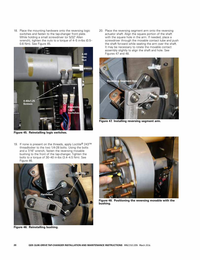
18. Place the mounting hardware onto the reversing logic switches and fasten to the tap-changer front plate. While holding a small screwdriver (or 5/32" Allen wrench), tighten the nuts to a torque of 4–5 in-lbs (0.5–0.6 Nm). See Figure 45.
19. If none is present on the threads, apply Loctite® 243™ threadlocker to the two 1/4-28 bolts. Using the bolts and a 7/16" wrench, fasten the reversing movable bushing to the front of the tap-changer. Tighten the bolts to a torque of 30–40 in-lbs (3.4–4.5 Nm). See Figure 46.
20. Place the reversing segment arm onto the reversing actuator shaft. Align the square portion of the shaft with the square hole in the arm. If needed, place a screwdriver through the movable contact tube and push the shaft forward while seating the arm over the shaft. It may be necessary to rotate the movable contact assembly slightly to align the shaft and hole. See Figures 47 and 48.
Figure 48. Positioning the reversing movable with the bushing.
Figure 46. Reinstalling bushing.
Figure 47. Installing reversing segment arm.
Reversing Segment Arm
Shaft
Figure 45. Reinstalling logic switches.
Reversing Logic Switches
4-40 Hex Nut
4-40x1.25 Screws
Hardware
Bushing
20 QD5 QUIK-DRIVE TAP-CHANGER INSTALLATION AND MAINTENANCE INSTRUCTIONS MN225012EN March 2016
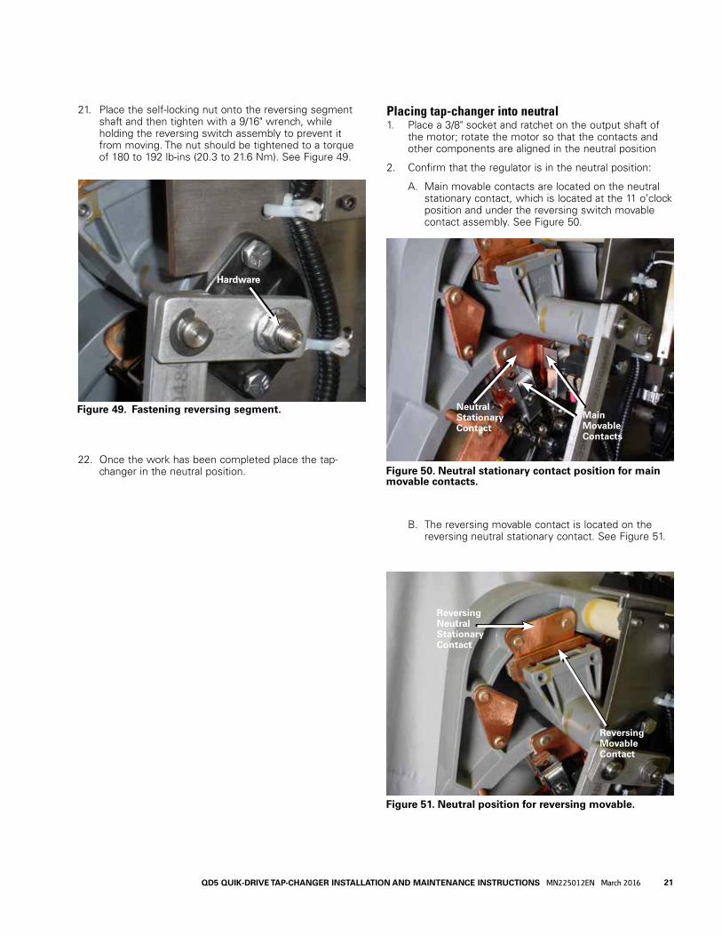
Placing tap-changer into neutral1. Place a 3/8" socket and ratchet on the output shaft of
the motor; rotate the motor so that the contacts and other components are aligned in the neutral position
2. Confirm that the regulator is in the neutral position:
A. Main movable contacts are located on the neutral stationary contact, which is located at the 11 o’clock position and under the reversing switch movable contact assembly. See Figure 50.
B. The reversing movable contact is located on the reversing neutral stationary contact. See Figure 51.
Figure 50. Neutral stationary contact position for main movable contacts.
Figure 51. Neutral position for reversing movable.
Reversing MovableContact
Reversing Neutral StationaryContact
21. Place the self-locking nut onto the reversing segment shaft and then tighten with a 9/16" wrench, while holding the reversing switch assembly to prevent it from moving. The nut should be tightened to a torque of 180 to 192 lb-ins (20.3 to 21.6 Nm). See Figure 49.
22. Once the work has been completed place the tap-changer in the neutral position.
Figure 49. Fastening reversing segment.
Hardware
Neutral StationaryContact
Main MovableContacts
21QD5 QUIK-DRIVE TAP-CHANGER INSTALLATION AND MAINTENANCE INSTRUCTIONS MN225012EN March 2016

C. The pinion cam is pointing to the right over the holding switch actuator. See Figure 52.
Figure 52. Neutral position for position indicator pinion cam and holding switch.
Pinion Cam
Holding Switch Actuator
22 QD5 QUIK-DRIVE TAP-CHANGER INSTALLATION AND MAINTENANCE INSTRUCTIONS MN225012EN March 2016
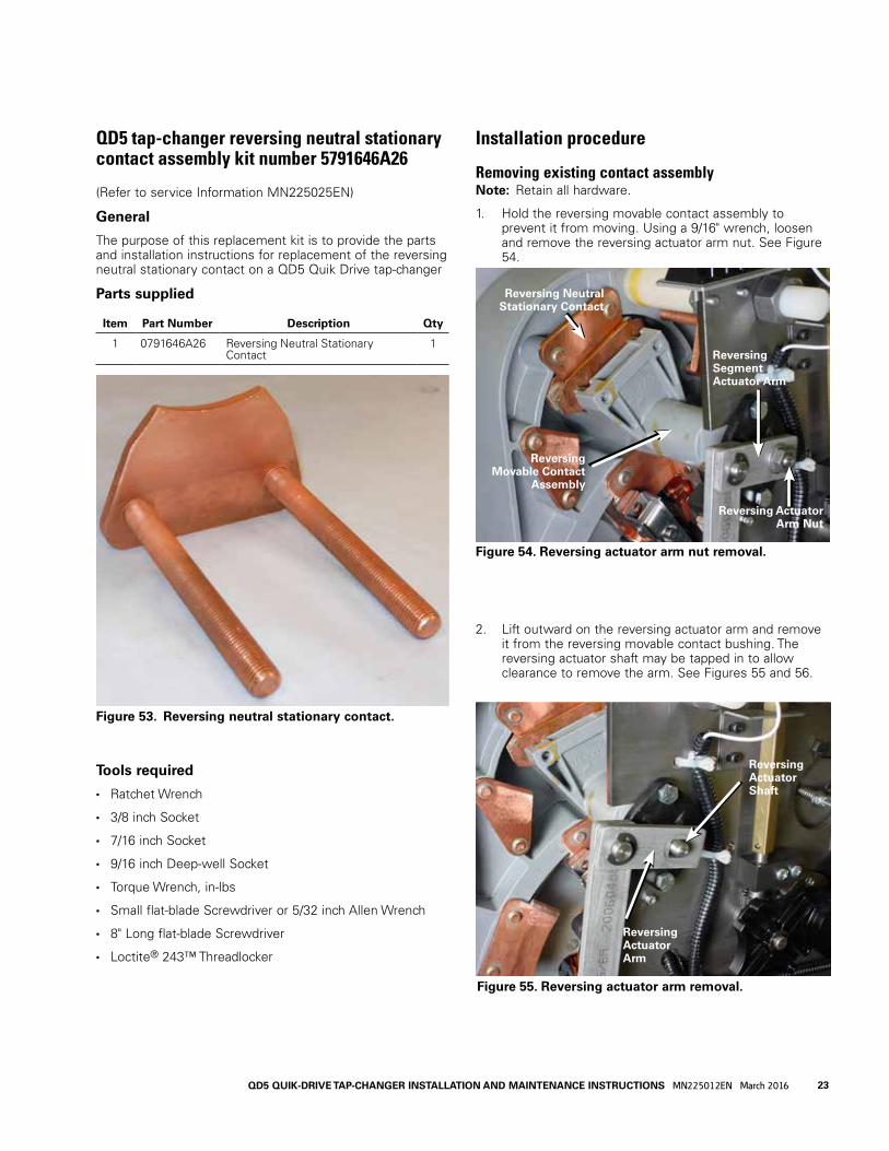
QD5 tap-changer reversing neutral stationary contact assembly kit number 5791646A26
(Refer to service Information MN225025EN)
General
The purpose of this replacement kit is to provide the parts and installation instructions for replacement of the reversing neutral stationary contact on a QD5 Quik Drive tap-changer
Parts supplied
Item Part Number Description Qty
1 0791646A26 Reversing Neutral Stationary Contact
1
Tools required
• Ratchet Wrench
• 3/8 inch Socket
• 7/16 inch Socket
• 9/16 inch Deep-well Socket
• Torque Wrench, in-lbs
• Small flat-blade Screwdriver or 5/32 inch Allen Wrench
• 8" Long flat-blade Screwdriver
• Loctite® 243™ Threadlocker
Installation procedure
Removing existing contact assemblyotee:N Retain all hardware.
1. Hold the reversing movable contact assembly to prevent it from moving. Using a 9/16" wrench, loosen and remove the reversing actuator arm nut. See Figure 54.
2. Lift outward on the reversing actuator arm and remove it from the reversing movable contact bushing. The reversing actuator shaft may be tapped in to allow clearance to remove the arm. See Figures 55 and 56.
Figure 53. Reversing neutral stationary contact.
Figure 55. Reversing actuator arm removal.
Reversing Actuator Shaft
Reversing Actuator Arm
Figure 54. Reversing actuator arm nut removal.
Reversing Neutral Stationary Contact
Reversing Segment Actuator Arm
Reversing Movable Contact
Assembly
Reversing Actuator Arm Nut
23QD5 QUIK-DRIVE TAP-CHANGER INSTALLATION AND MAINTENANCE INSTRUCTIONS MN225012EN March 2016
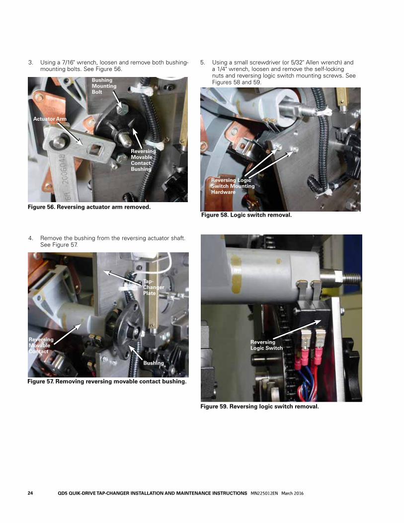
3. Using a 7/16" wrench, loosen and remove both bushing-mounting bolts. See Figure 56.
4. Remove the bushing from the reversing actuator shaft. See Figure 57.
5. Using a small screwdriver (or 5/32" Allen wrench) and a 1/4" wrench, loosen and remove the self-locking nuts and reversing logic switch mounting screws. See Figures 58 and 59.
Figure 57. Removing reversing movable contact bushing.
Bushing
Reversing Movable Contact
Tap-Changer Plate
Figure 58. Logic switch removal.
Reversing Logic Switch Mounting Hardware
Figure 59. Reversing logic switch removal.
Reversing Logic Switch
Figure 56. Reversing actuator arm removed.
Actuator Arm
Bushing Mounting Bolt
Reversing Movable Contact Bushing
24 QD5 QUIK-DRIVE TAP-CHANGER INSTALLATION AND MAINTENANCE INSTRUCTIONS MN225012EN March 2016

6. After the removal of the reversing logic switch mounting screws, the switch will drop away from the reversing movable switch tube. See Figure 60.
7. Using a 9/16" wrench, loosen and remove the nuts and flat washers from both of the reversing neutral stationary contacts on the back of the tap-changer contact panel. See Figure 61.
8. Pull the reversing movable contact assembly and the reversing neutral stationary contact forward toward the steel front panel as far as possible. See Figure 62.
9. Rotate the reversing movable contact counter clockwise until the movable contact assemble disengages from the reversing neutral stationary contact and remove it from the tap-changer. See Figure 63.
10. Remove the reversing neutral stationary contact assembly from the tap-changer contact panel.
Figure 61. Reversing neutral stationary contact hardware.
Reversing Neutral Stationary Contact Hardware
Figure 62. Removing movable contact assembly.
Reversing Movable Contact
Neutral Reversing Stationary Contact
Figure 63. Removing reversing movable contact.
Neutral Stationary Contact
Removing Reversing Movable Assembly
Reversing Movable Contact
Figure 60. Reversing movable contact switch.
Logic Switch
Reversing Logic Movable Contact Tube
25QD5 QUIK-DRIVE TAP-CHANGER INSTALLATION AND MAINTENANCE INSTRUCTIONS MN225012EN March 2016
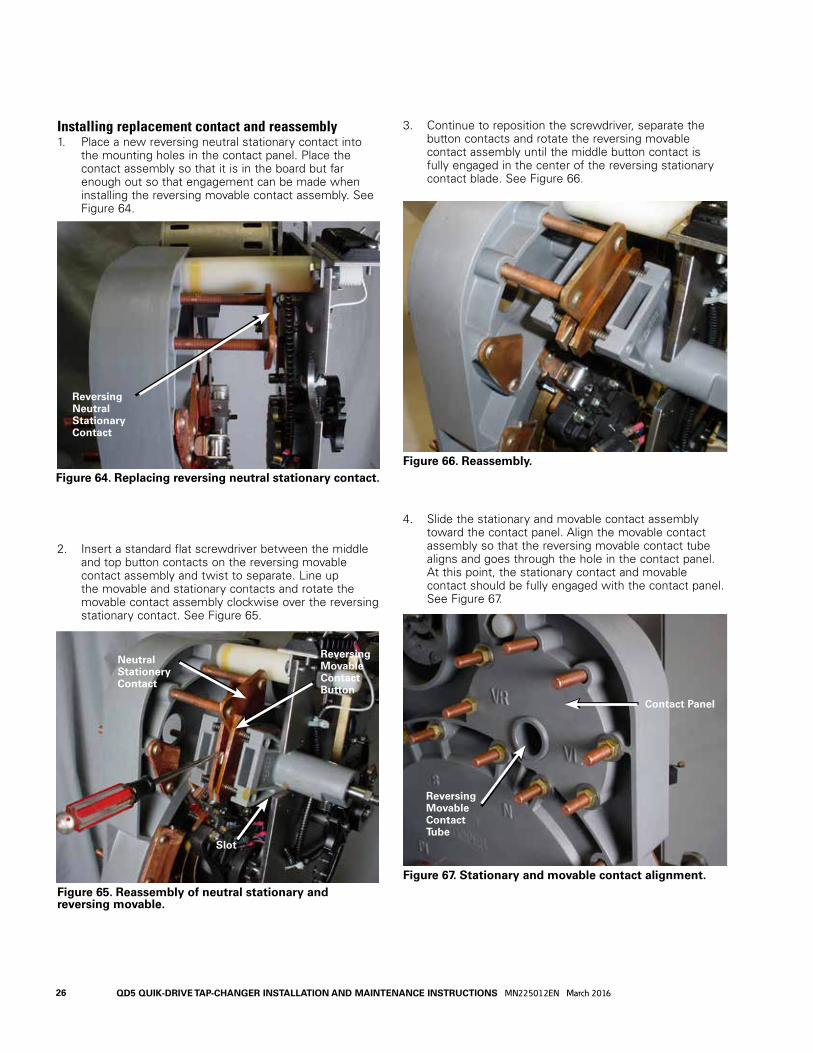
Installing replacement contact and reassembly1. Place a new reversing neutral stationary contact into
the mounting holes in the contact panel. Place the contact assembly so that it is in the board but far enough out so that engagement can be made when installing the reversing movable contact assembly. See Figure 64.
2. Insert a standard flat screwdriver between the middle and top button contacts on the reversing movable contact assembly and twist to separate. Line up the movable and stationary contacts and rotate the movable contact assembly clockwise over the reversing stationary contact. See Figure 65.
3. Continue to reposition the screwdriver, separate the button contacts and rotate the reversing movable contact assembly until the middle button contact is fully engaged in the center of the reversing stationary contact blade. See Figure 66.
4. Slide the stationary and movable contact assembly toward the contact panel. Align the movable contact assembly so that the reversing movable contact tube aligns and goes through the hole in the contact panel. At this point, the stationary contact and movable contact should be fully engaged with the contact panel. See Figure 67.
Figure 64. Replacing reversing neutral stationary contact.
Figure 67. Stationary and movable contact alignment.Figure 65. Reassembly of neutral stationary and reversing movable.
Figure 66. Reassembly.
Reversing Neutral Stationary Contact
Contact Panel
Reversing Movable Contact Tube
Neutral Stationery Contact
Reversing Movable Contact Button
Slot
26 QD5 QUIK-DRIVE TAP-CHANGER INSTALLATION AND MAINTENANCE INSTRUCTIONS MN225012EN March 2016

5. Place a flat washer and nut over each of the reversing neutral stationary contact studs. Tighten to a torque of 80–90 in-lbs (9.0–10.2 Nm). See Figure 68.
6. Place the mounting hardware onto the reversing logic switches and fasten to the tap-changer front plate. While holding a small screwdriver, tighten the nuts to a torque of 4–5 in-lbs (0.5–0.6 Nm). See Figure 69.
7. If not present on the threads, apply Loctite® 243™ threadlocker to the two 1/4-28 bolts. Using the bolts and a 7/16" wrench, fasten the reversing movable bushing to the front of the tap-changer. Tighten the bolts to a torque of 30–40 in-lbs (3.4–4.5 Nm). See Figure 70.
8. Place the reversing segment arm onto the reversing actuator shaft. Align the square portion of the shaft with the square hole in the arm. If needed, place a screwdriver through the movable contact tube and push the shaft forward while seating the arm over the shaft. It may be necessary to rotate the movable contact assembly slightly to align the shaft and hole. See Figures 71 and 72.
Figure 67. Reversing neutral stationary contact fastening.
Figure 69. Reversing logic switch mounting.
Figure 70. Reversing segment gear shaft.
Reversing Neutral Stationary Contact Studs
Reversing Logic Switches
4-40 Hex Nut
4-40x1.25 Screws
1/4-28 Bolts
Reversing Segment Shaft
Figure 71. Placement of reversing segment arm.
Reversing Segment Arm
Reversing Segment Gear Shaft
27QD5 QUIK-DRIVE TAP-CHANGER INSTALLATION AND MAINTENANCE INSTRUCTIONS MN225012EN March 2016

9. Place the self-locking nut onto the reversing segment shaft. Using a 9/16" wrench, tighten to a torque of 180–192 in-lbs (20.3–21.7 Nm) while holding the movable contact assembly to prevent turning. See Figure 73.
10. Once the work has been completed, place the tap-changer in the neutral position.
Placing tap-changer into neutral1. Place a 3/8" socket and ratchet on the output shaft of
the motor; rotate the motor so that the contacts and other components are aligned in the neutral position
2. Confirm that the regulator is in the neutral position.
A. Main movable contacts are located on the neutral stationary contact, which is located at the 11 o’clock position and under the reversing switch movable contact assembly. See Figure 74.
Figure 73. Reversing segment fastening.
Reversing Segment Shaft
3/8-16 Self-Locking Nut
Figure 74. Neutral position for main movable contacts.
Figure 72. Pushing the reversing segment shaft forward.
Screwdriver or Shaft Rod
Neutral Stationary
Main Movable
28 QD5 QUIK-DRIVE TAP-CHANGER INSTALLATION AND MAINTENANCE INSTRUCTIONS MN225012EN March 2016

B. The reversing movable contact is located on the reversing neutral stationary contact. See Figure 75.
C. The pinion cam is pointing to the right over the holding switch actuator. See Figure 76.
Figure 75. Neutral position for reversing movable.
Reversing Movable Contact
Reversing Neutral Stationary Contact
Figure 76. Neutral position for position indicator pinion cam and holding switch.
Pinion Cam
Holding Switch Actuator
29QD5 QUIK-DRIVE TAP-CHANGER INSTALLATION AND MAINTENANCE INSTRUCTIONS MN225012EN March 2016

Installation procedure
Stationary contact removal and installation instructions1. Each QD5 tap-changer has nine main stationary
contacts. Of these, eight are tap contacts and one is the neutral stationary contact. See Figure 78.
2. Use a 9/16" deep-well socket and ratchet to loosen and remove the nuts and washers from each stationary contact stud. See Figure 79.
QD5 tap-changer main stationary contact assembly kit 5791646A24
(Refer to Service Information MN225026EN)
General
The purpose of this replacement kit is to provide the parts and installation instructions for replacing the main stationary contacts on a QD5 Quik Drive tap-changer.
Parts supplied
Item Part Number Description Qty
1 0791646A24 Stationary Contact 1
Tools required• Ratchet Wrench
• 9/16 inch Deep-well Socket
• Torque Wrench in-lbs
• 3/8 inch Socket
Figure 78. Stationary contacts.
Neutral Stationary Contact
Stationary Contacts
Figure 79. Removal of contact hardware.
Figure 77. Main stationary contact.
30 QD5 QUIK-DRIVE TAP-CHANGER INSTALLATION AND MAINTENANCE INSTRUCTIONS MN225012EN March 2016

3. Remove the stationary contact from the contact assembly panel. See Figure 79.
4. Install the new stationary contact into the mounting holes in the contact assembly board for the contact being replaced. See Figure 80.
5. Place a flat washer and nut on each stud. Use a 9/16" deep-well socket and ratchet to tighten the nuts. Using a torque wrench, tighten the nuts to a torque of 80–90 in-lbs (9.0–10.2 Nm). See Figure 81.
6. Repeat Steps 1 through 5 for each stationary contact to be replaced.
7. When the movable contacts are located on the stationary contact to be replaced, the movable contacts must be moved. Place a 3/8" socket onto the rear shaft of the motor. See Figure 82. Using a ratchet, rotate the motor to position the movable contacts off of the contact to be replaced.
8. Once the work has been completed, place the tap-changer in the neutral position.
Figure 81. Contact hardware installation.
Nut
Washer
Figure 82. Motor and movable contact rotation.
Motor Shaft
Back Side of Contact Panel
3/8" Socket and Ratchet
Figure 80. Stationary contact removal.
31QD5 QUIK-DRIVE TAP-CHANGER INSTALLATION AND MAINTENANCE INSTRUCTIONS MN225012EN March 2016

B. The reversing movable contact is located on the reversing neutral stationary contact. See Figure 84.
C. The pinion cam is pointing to the right over the holding switch actuator. See Figure 85.
Placing tap-changer into neutral1. Place a 3/8" socket and ratchet on the output shaft of
the motor; rotate the motor so that the contacts and other components are aligned in the neutral position
2. Confirm that the regulator is in the neutral position.
A. Main movable contacts are located on the neutral stationary contact, which is located at the 11 o’clock position and under the reversing switch movable contact assembly. See Figure 83.
Figure 84. Neutral position for reversing movable.
Reversing Movable Contact
Reversing Neutral Stationary Contact
Figure 85. Neutral position for position indicator pinion cam and holding switch.
Figure 83. Neutral position for main movable contacts.
Main MovableContacts
Neutral StationaryContact
Pinion Cam
Holding Switch Actuator
32 QD5 QUIK-DRIVE TAP-CHANGER INSTALLATION AND MAINTENANCE INSTRUCTIONS MN225012EN March 2016

Installation procedure
VL reversing stationary contact removal and installation1. Each QD5 tap-changer has one VL reversing stationary
contact. See Figure 87.
2. If the reversing movable contacts are setting on the VL reversing stationary contact, place a 3/8" socket onto the rear shaft of the motor. See Figure 88. Using a ratchet, rotate the motor shaft counter-clockwise to move the reversing movable contacts off of the reversing stationary contact. It may be necessary to rotate the tap changer through several positions before the movable reversing contact will begin to move.
QD5 tap-changer VL reversing stationary contact assembly kit number 5791646A25
(Refer to Service Information MN225027EN)
General
The purpose of this replacement kit is to provide the parts and installation instructions for replacement of the VL reversing stationary contacts on a QD5 Quik Drive tap-changer.
Parts supplied
Item Part Number Description Qty
1 0791646A25 VL Reversing Stationary Contact
1
Tools required• Ratchet Wrench
• 9/16 inch Deep-well Socket
• Torque Wrench in-lbs
• 3/8 inch Socket
Figure 86. VL reversing stationary contact.
Figure 87. VL reversing stationary contact location.
VL Reversing Stationary Con-tact
VR Reversing Stationary ContactReversing Neutral
Stationary Contact
Figure 88. Motor and reversing movable contact rotation.
Motor Shaft
33QD5 QUIK-DRIVE TAP-CHANGER INSTALLATION AND MAINTENANCE INSTRUCTIONS MN225012EN March 2016

3. To remove a VL Reversing Stationary Contact, use a 9/16" socket and ratchet to loosen and remove the nuts and flat washers from each of the contact studs. See Figure 89.
4. Remove the VL reversing stationary contact from the contact assembly panel. See Figure 90.
5. Install the new VL reversing stationary contact into the mounting holes in the contact assembly board. Make sure when installing the contact that the leading tapered edge is positioned toward the reversing neutral stationary contact. If the tapered edge is facing in the wrong direction, the stationary VR contact is being used. See Figure 90.
6. Place a flat washer and nut on each stud. Use a 9/16" socket and ratchet to tighten the nuts on each contact stud. Using a torque wrench tighten the nuts to a torque of 80–90 in-lbs (9.0–10.2 Nm). See Figures 91.
7. Once the work has been completed, place the tap-changer in the neutral position.
Figure 90. VL reversing stationary contact removal.
Tapered Edge
Figure 91. VL reversing stationary hardware.
Nuts and Washers
Figure 89. VL reversing stationary hardware and ID.
VL Contact Studs
VL Stationary Con-tact ID Marker
34 QD5 QUIK-DRIVE TAP-CHANGER INSTALLATION AND MAINTENANCE INSTRUCTIONS MN225012EN March 2016
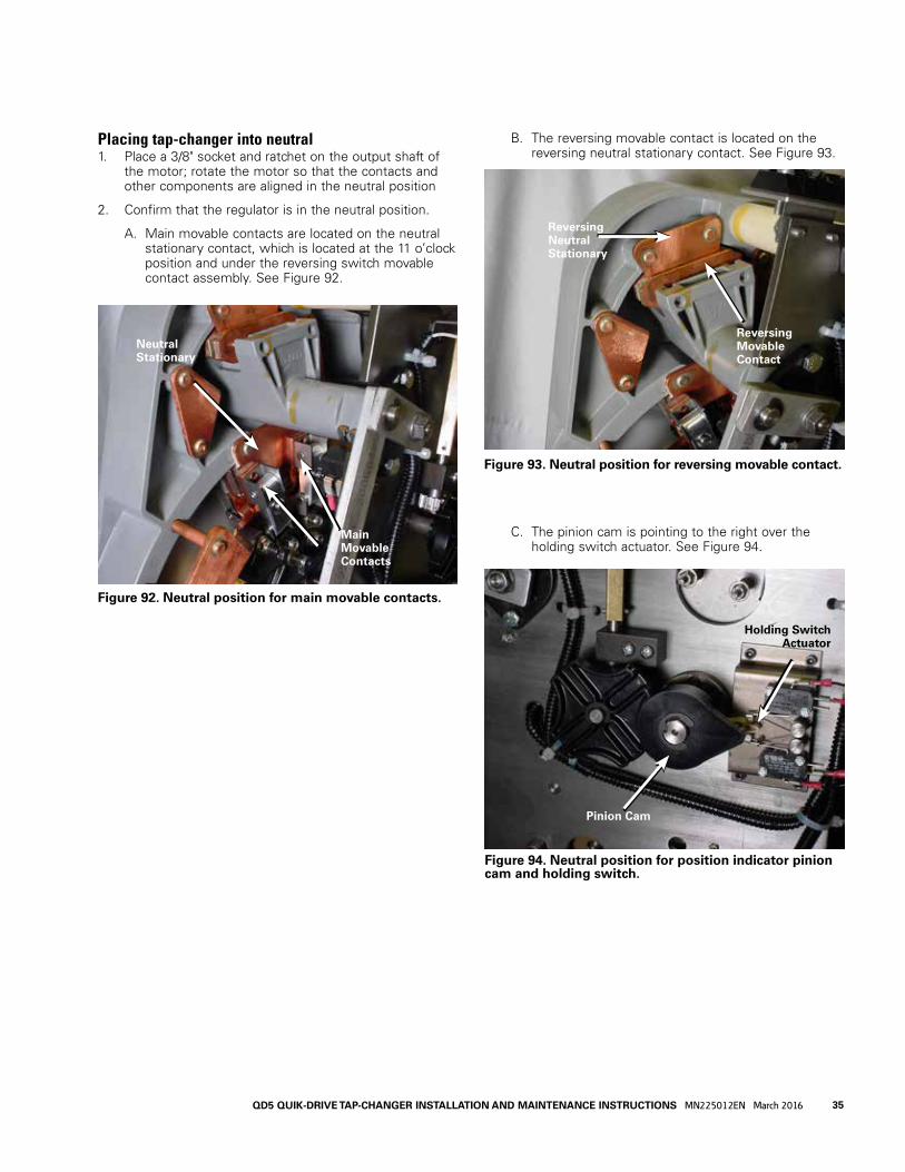
B. The reversing movable contact is located on the reversing neutral stationary contact. See Figure 93.
C. The pinion cam is pointing to the right over the holding switch actuator. See Figure 94.
Placing tap-changer into neutral1. Place a 3/8" socket and ratchet on the output shaft of
the motor; rotate the motor so that the contacts and other components are aligned in the neutral position
2. Confirm that the regulator is in the neutral position.
A. Main movable contacts are located on the neutral stationary contact, which is located at the 11 o’clock position and under the reversing switch movable contact assembly. See Figure 92.
Figure 93. Neutral position for reversing movable contact.
Reversing MovableContact
Reversing Neutral Stationary
Figure 92. Neutral position for main movable contacts.
Neutral Stationary
Main MovableContacts
Figure 94. Neutral position for position indicator pinion cam and holding switch.
Pinion Cam
Holding Switch Actuator
35QD5 QUIK-DRIVE TAP-CHANGER INSTALLATION AND MAINTENANCE INSTRUCTIONS MN225012EN March 2016

Installation procedure
VR reserving stationary contact removal and installation1. Each QD5 tap-changer has one VR reversing stationary
contact. Note that in the photo, the nylon separating bar has been removed. It is not necessary to remove the bar to perform these steps. See Figure 96.
2. If the reversing movable contacts are located on the VR reversing stationary contact, place a 3/8" socket onto the rear shaft of the motor. See Figure 97. Using a ratchet, rotate the motor shaft clockwise to move the reversing movable contacts off of the reversing stationary contact. It may be necessary to rotate the tap-changer through several positions before the movable reversing contact will begin to move.
QD5 tap-changer VR reversing stationary contact assembly kit number 5791646A27
(Refer to Service Information MN225028EN)
General
The purpose of this replacement kit is to provide the parts and installation instructions for replacing the VR reversing stationary contacts on a QD5 Quik Drive tap-changer.
Parts supplied
Item Part Number Description Qty
1 0791646A27 VR Reversing Stationary Contact
1
Tools required
• Ratchet Wrench
• 9/16 inch Deep-well Socket
• Torque Wrench in-lbs
• 3/8 inch Socket
Figure 96. Reversing stationary contact.
VL Stationary Neutral Stationary
VR Stationary Contact
Figure 97. Motor and reversing movable contact rotation.
Motor Shaft
Back Side of Contact Panel
3/8 - Socket and Ratchet
Figure 95. VR reversing stationary contact.
36 QD5 QUIK-DRIVE TAP-CHANGER INSTALLATION AND MAINTENANCE INSTRUCTIONS MN225012EN March 2016

3. To remove a VR Reversing Stationary Contact use a 9/16" socket and ratchet to loosen and remove both the nuts and flat washers from each of the contact studs. See Figure 98.
4. Remove the VR reversing stationary contact from the contact assembly panel. See Figure 106.
5. Install the new VR reversing stationary contact into the mounting holes in the contact assembly board. Make sure when installing the contact that the leading tapered edge is positioned toward the reversing neutral stationary contact. If the tapered edge is facing in the wrong direction, the stationary VL contact is being used. See Figure 99.
6. Place a flat washer and nut on each stud. Use a 9/16" socket and ratchet to tighten the nuts on each contact stud. Using a torque wrench tighten the nuts to a torque of 80–90 lb-ins (9.0–10.2 Nm). See Figures 100.
7. Once the work has been completed, place the tap-changer in the neutral position.
Figure 98. Reassembling hardware.
VR Stationary Hardware
Figure 100. Removing hardware.
VR Stationary Hardware
Figure 99. VR reversing stationary contact removal
Tapered Edge
37QD5 QUIK-DRIVE TAP-CHANGER INSTALLATION AND MAINTENANCE INSTRUCTIONS MN225012EN March 2016

Placing tap-changer into neutral1. Place a 3/8" socket and ratchet on the output shaft of
the motor; rotate the motor so that the contacts and other components are aligned in the neutral position
2. Confirm that the regulator is in the neutral position.
A. Main movable contacts are located on the neutral stationary contact, which is located at the 11 o’clock position and under the reversing switch movable contact assembly. See Figure 101.
B. The reversing movable contact is located on the reversing neutral stationary contact. See Figure 102.
Figure 101. Neutral stationary contact.
Neutral StationaryContact Main
MovableContacts
Figure 102. Neutral position for reversing movable.
Reversing MovableContact
Reversing Neutral Stationary
C. The pinion cam is pointing to the right over the holding switch actuator. See Figure 103.
Figure 103. Neutral position for position indicator pinion cam and holding switch.
Pinion Cam
Holding Switch Actuator
38 QD5 QUIK-DRIVE TAP-CHANGER INSTALLATION AND MAINTENANCE INSTRUCTIONS MN225012EN March 2016

QD5 tap-changer motor replacement procedure kit number 57A63675100A
(Refer to Service Information MN225029EN)
General
The purpose of this replacement kit is to provide the parts and installation instructions for replacing the motor on a QD5 Quik Drive tap-changer.
Parts supplied
Item Part Number Description Qty
1 2242190B01 QD8/QD5 Motor 1
2 TAA114651003 Ring terminal 3
3 0800011079Z Wire ties 3
4 2240787B34 Motor sprocket (12-tooth) 1
5 2291647A34 Woodruff key 1
6 0800073173Z Retaining ring 2
7 0800073190Z Machine screw, 8-32x0.5 4
8 2240787B44 Motor sprocket (11-tooth) 1
Tools required• Ratchet Wrench
• 9/16 inch Socket
• 3/4 inch Socket
• 7/16 inch Combination Wrench
• 1/4 inch Socket
• 3/8 inch Socket
• Phillips Head Screwdriver #2
• Standard Blade Screwdriver
• Diagonal Cutters
• Loctite® 243™ Threadlocker
• External Snap Ring Pliers
• 0-200 in-lbs (0-25 Nm) Torque Wrench
• Crimping Tool
• Pliers
Installation procedure
1. The QD5 tap-changer should be secured to a bench before starting the replacement procedure if the tap-changer has been removed from the unit.
2. The tap-changer should be in the neutral position before starting the replacement procedure. Refer to Figure 105. If the tap-changer is not in the neutral position, turn the back of the motor shaft using a 3/8" socket on a ratchet until the tap-changer is in the neutral position.
Contacts in the Neutral Position
Figure 105. Neutral position.Figure 104. Tap-changer motor replacement kit.
39QD5 QUIK-DRIVE TAP-CHANGER INSTALLATION AND MAINTENANCE INSTRUCTIONS MN225012EN March 2016

3. Use diagonal cutters to cut the four wire ties from the motor wires. Refer to Figure 106.
4. Use a Phillips screwdriver to disconnect the white motor wire located on terminal “G”, the red motor wire located on terminal #5 and the blue motor wire located on terminal #2. Refer to Figure 107.
5. Loosen the jam nut on the chain tension screw with a 7/16" wrench. Loosen the chain tension screw with a screwdriver until the rubber bumper is against the motor mounting bracket. Refer to Figure 108.
6. If the tap-changer has a motor pivot stud design with a lock nut as shown in Figure 109, remove the motor pivot stud lock nut with a 9/16" socket on a ratchet. Pull the motor off of the motor pivot stud; make sure the Belleville washer stays on the motor pivot stud and does not fall into the tank. Set the motor in the motor relief area of the molded back panel. Refer to Figure 113.
Figure 106. Removal of wire ties.
Cut These Four Wire Ties
Figure 107. Disconnection of wires.
Figure 108. Loosening the chain tension.
White Motor Wire
Terminal BoardBlue Motor Wire
Red Motor Wire
Motor Mounting Bracket
Chain Tension Screw
Jam Nut
Rubber Bumper
Figure 109. Motor pivot stud design.
Motor Pivot Stud
Motor Pivot Lock Nut
Belleville Washer
40 QD5 QUIK-DRIVE TAP-CHANGER INSTALLATION AND MAINTENANCE INSTRUCTIONS MN225012EN March 2016
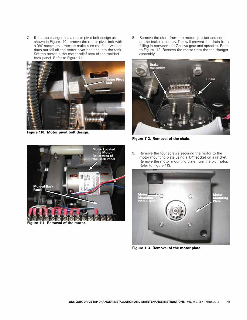
7. If the tap-changer has a motor pivot bolt design as shown in Figure 110, remove the motor pivot bolt with a 3/4" socket on a ratchet; make sure the fiber washer does not fall off the motor pivot bolt and into the tank. Set the motor in the motor relief area of the molded back panel. Refer to Figure 111.
8. Remove the chain from the motor sprocket and set it on the brake assembly. This will prevent the chain from falling in between the Geneva gear and sprocket. Refer to Figure 112. Remove the motor from the tap-changer assembly.
9. Remove the four screws securing the motor to the motor mounting plate using a 1/4" socket on a ratchet. Remove the motor mounting plate from the old motor. Refer to Figure 113.
Figure 112. Removal of the chain.
Brake Assembly
Chain
Figure 113. Removal of the motor plate.
Motor Mounting Plate Screw
Motor Mounting Plate
Figure 111. Removal of the motor.
Motor Located in the Motor Relief Area of the Back Panel
Molded Back Panel
Figure 110. Motor pivot bolt design.
Motor Pivot Bolt
41QD5 QUIK-DRIVE TAP-CHANGER INSTALLATION AND MAINTENANCE INSTRUCTIONS MN225012EN March 2016

10. The new motor kit (Part # 57A636751A100A) has a 12 tooth sprocket for the QD8 tap-changer and an 11 tooth sprocket for the QD5 tap-changer. The motor shaft has two snap ring grooves and a woodruff keyway. Install a snap ring with a snap ring pliers into the inner snap ring groove behind the woodruff keyway. Using a pliers, put the woodruff key into the keyway with the woodruff key tilted down towards the end of the motor shaft. Refer to Figure 114.
11. Align the sprocket keyway with the woodruff key on the motor shaft. Slide the sprocket onto the motor shaft with the sprocket hub end towards the motor. Install the second snap ring into the outer snap ring groove using a snap ring pliers. Refer to Figure 115.
Figure 114. Woodruff key placement.
Snap RingWoodruff Key
Snap Ring Groove
12. Use a 1/4" socket on a ratchet to attach the motor mounting plate to the new motor using the new motor mounting plate screws provided in the motor replacement kit. Do not fully tighten. Make sure the motor wires are extending out of the top right of the motor when looking at the motor from the sprocket end. Refer to Figure 116. Using a torque wrench, now tighten the motor plate mounting screws to 18–20 lb-ins (2.0–2.2 Nm).
13. Place the motor into the motor relief area of the molded back panel. Put the chain on the motor sprocket engaging the sprocket teeth. Make sure the chain is fully engaged around the bottom of the drive sprocket gear. If there are any loose links around the bottom of the gear, the motor will not fit properly. Refer to Figure 117.
otee:N If you have the motor pivot stud design as shown in Figure 113, follow Step 13. If you have the motor pivot bolt design as shown in Figure 114, follow Step 14.
Figure 115. Placement of the sprocket.
Figure 116. Motor mounting plate.
Figure 117. Locating motor.
Sprocket Hub
Outer Snap Ring
Motor Mounting Plate Screw
Sprocket End of the Motor
Motor Wires
Molded Back Panel Motor Relief Area
Motor Chain Adjustment Bracket
42 QD5 QUIK-DRIVE TAP-CHANGER INSTALLATION AND MAINTENANCE INSTRUCTIONS MN225012EN March 2016

15. Apply Loctite® 243™ threadlocker on the threads of the motor pivot bolt and verify the fiber washer is still located on the motor pivot bolt shoulder. Refer to Figure 120. Move the motor assembly into position with the motor chain adjustment screw bumper located on top of the adjustment bracket. Refer to Figure 118. Align the hole in the motor mounting plate with the hex spacer hole. Insert the motor pivot bolt through the motor mounting plate and hand tighten into the hex spacer. Refer to Figure 124. Make sure that the shoulder on the bolt is completely inserted through the hole in the motor mounting bracket. Using a torque wrench with a 3/4" socket, tighten the motor pivot bolt to 45–55 in-lbs (5.0–6.1 Nm).
14. Move the motor assembly into position with the motor chain adjustment screw bumper located on top of the adjustment bracket and the motor pivot stud inserted through the mounting hole in the motor mounting plate. Secure the motor mounting plate to the motor pivot stud with the locknut removed in Step 6. Refer to Figures 118 and 119. Using a torque wrench with a 9/16" socket, tighten the pivot motor stud locknut to 180–192 in-lbs (20.0–21.1 Nm). Proceed to Step 16.
Figure 121. Placement of motor pivot bolt.
Motor Pivot Bolt
Hex Spacer
Figure 118. Motor positioning.
Motor Chain Adjustment Bracket
Motor Chain Adjustment Screw
Chain Adjust-ment Screw Bumper
Figure 120. Motor pivot bolt.
Fiber Washer
Motor Pivot BoltLoctite® 243™ Threadlocker
Shoulder
Figure 119. Motor pivot stud.
Motor Pivot Stud
Lock Nut
IMPORTANT Make sure that the mounting hole in the motor mounting bracket is fully seated on the shoulder of the mounting bolt. If it is not fully seated, the chain may bind and fall off.
IMPORTANT Make sure that the mounting hole in the motor mounting bracket is fully seated on the shoulder of the mounting bolt. If it is not fully seated, the chain may bind and fall off.
43QD5 QUIK-DRIVE TAP-CHANGER INSTALLATION AND MAINTENANCE INSTRUCTIONS MN225012EN March 2016

16. Adjust the chain tension by turning the motor bumper screw with a blade screw driver. Adjust the motor mount bumper screw until 1/4” deflection exists when exerting pressure on the chain. Secure the motor mount bumper screw in place with the jam nut using a 7/16" wrench. Refer to Figure 122.
17. The motor wire connection points are as follows: the white wire connects to terminal “G”, the red wire connects to terminal #5 and the blue wire connects to terminal #2. Trim the motor wires with a diagonal cutter allowing an extra two inches of wire between the motor and the connection points. Strip 1/4" of wire insulation from the end of each wire. Crimp a supplied ring tongue connector to the end of each wire, making sure the wire is fully inserted into the ring tongue connector. The wire should not stick out of the connector by more than 1/16 (1.5 mm) of an inch. Attach the ring tongues to the motor connection points on the terminal board as described above. Refer to Figure 123.
Figure 122. Chain tension.
Jam Nut
Motor Mount Bumper Screw
18. Use the wire ties provided in the motor replacement kit to bundle all the wires near the terminal board to complete the motor replacement procedure. Refer to Figure 124.
19. Ensure that the tap-changer is in the neutral position when the work is completed.
Figure 123. Wiring connections.
Figure 124. Wire fastening.
44 QD5 QUIK-DRIVE TAP-CHANGER INSTALLATION AND MAINTENANCE INSTRUCTIONS MN225012EN March 2016

C. The pinion cam is pointing to the right over the holding switch actuator. See Figure 127.
Placing tap-changer into neutral1. Place a 3/8" socket and ratchet on the output shaft of
the motor; rotate the motor so that the contacts and other components are aligned in the neutral position
2. Confirm that the regulator is in the neutral position.
A. Main movable contacts are located on the neutral stationary contact, which is located at the 11 o’clock position and under the reversing switch movable contact assembly. See Figure 125.
B. The reversing movable contact is located on the reversing neutral stationary contact. See Figure 126.
Figure 125. Neutral stationary contact.
Neutral Stationary
Main Movables
Figure 127. Neutral position for position indicator pinion cam and holding switch.
Figure 126. Neutral position for reversing movable.
Reversing MovableContact
Reversing Neutral Stationary
Pinion Cam
Holding Switch Actuator
45QD5 QUIK-DRIVE TAP-CHANGER INSTALLATION AND MAINTENANCE INSTRUCTIONS MN225012EN March 2016

QD5 tap-changer main movable contact replacement kit number 5740785B33
(Refer to Service Information MN225030EN)
General
The purpose of this replacement kit is to provide the parts and installation instructions for replacing the main movable contacts on a QD5 Quik-Drive tap-changer.
Parts supplied
Item Part Number Description Qty
1 5740785B33 Main Movable Contact Replacement Kit
1
Tools required• Ratchet Wrench
• 3/4 inch Socket
• 3/8 inch Socket
• 7/16 inch Deep-well Socket
• 9/16 inch Deep-well Socket
• 5/8 inch open end Wrench
• Torque Wrench 0-300 in-lbs
• Small-bladed Screwdrivers (2)
• Bladed Screwdriver
• 5/32 inch hex Wrench
• Lineman's Pliers
• Locktite® 243 Threadlocker
Installation procedure
1. The tap-changer should be secured to a bench before starting the replacement procedure if the tap-changer has been removed from the unit.
2. The tap-changer should be in the neutral position before starting the replacement procedure. Refer to Figure 129. If the tap-changer is not in the neutral position, turn the shaft on the back of the motor shaft using a 3/8" socket on a ratchet until the QD5 tap-changer is in the neutral position.
3. Remove the number 1 stationary contact from the molded panel using a 9/16" deep well socket wrench. Refer to Figure 130.
Figure 129. Neutral position.
Contacts in the Neutral Position
Figure 130. Stationary contact.
Molded Panel
First Raise Stationary Contact Removed
Neutral Stationary Contact
Figure 128. Main movable contact replacement kit.
46 QD5 QUIK-DRIVE TAP-CHANGER INSTALLATION AND MAINTENANCE INSTRUCTIONS MN225012EN March 2016

4. Using a 3/8” socket on a ratchet, rotate the shaft on the back of the motor to move the movable contacts into the space opened up when the number 1 stationary contact was removed.
5. Remove the two bolts that mount the actuator finger with a 7/16" socket wrench. Remove the actuator finger. Refer to Figure 132.
6. Remove the nut on the end of the main shaft using a 3/4" socket wrench. Use a 5/8" open end wrench positioned on the flats of the main shaft to hold the shaft in place during this procedure. Refer to Figures 133 and 134.
7. Push the main shaft from the threaded end partially through the steel front plate of the tap-changer so that the retaining ring on the main shaft is centered between the movable contact panel and the washer/Geneva gear hub. Refer to Figure 135.
Figure 134. Main shaft.
Flats on the Main Shaft
Figure 133. Fastening nut for main shaft.
Nut on the end of the Main Shaft
Main Shaft
Figure 135. Shaft positioning.
Washer
Geneva Gear Hub
Retaining Ring
Movable Contact Panel
Figure 132. Actuator finger.
Remove These Two Bolts
Actuator Finger
Figure 131. Main movable contacts in number 1 station-ary position.
47

8. Use a pair of lineman's pliers to remove the retaining ring. Slide the washer up against the movable contact panel. Refer to Figure 136.
9. Push the threaded end of the main shaft through the steel panel toward the molded panel. Support the Geneva gear with one hand and pull the main shaft out from the back of the molded panel until the main shaft is out of the Geneva gear hub. Make sure the washer remains on the shaft and does not fall into the tank. Remove the Geneva gear and slide the washer off the shaft. Refer to Figure 137.
10. Pull the main shaft completely out of the back of the molded panel. Pull the contact rings out of the button contacts and remove the movable contact panel assembly. Refer to Figure 138.
11. Remove the three button head screws, nuts and washers that secure each contact to the movable contact panel using a 5/32" hex wrench and a 7/16" deep well socket wrench. Refer to Figures 139 and 140.
otee:N The center button head screw on each movable contact assembly has a flat washer and a Belleville washer under the nut.
Figure 137. Removal of shaft.
Figure 138. Removal of main contacts.
Button Contacts
Figure 139. Movable contact removal from insulating arm and rings.
Button Head Screw
Movable Contact Assemblies
Figure 136. Washer.
Washer
48 QD5 QUIK-DRIVE TAP-CHANGER INSTALLATION AND MAINTENANCE INSTRUCTIONS MN225012EN March 2016

13. Position and center the movable contact panel assembly in the molded panel cavity with the contact rings facing the molded panel. Locate the movable contacts in the area of the removed stationary contact. Rotate the movable contact panel and slide the movable contacts onto the neutral stationary contact. Align the contact rings with the button contacts. Refer to Figure 143.
14. For the outer contact ring, spread the button contacts using a bladed screwdriver and insert the contact ring between the contact buttons. See Figure 142.
15. For the inner contact ring, from the back of the molded panel, insert a small blade screwdriver between the button contact spring and the button contact shunt on each side of the contact. Refer to Figure 143.
12. The two replacement movable contact assemblies are identical; therefore, they can be installed in either position on the movable contact panel. Position one of the replacement movable contact assemblies between the contact ring and the movable contact panel and align the holes. Insert the three button head screws from the contact ring side of the assembly so the screw heads secure the contact ring in place. On the side opposite the contact ring, place a flat washer on all three screws. Place a Belleville washer on the center screw and thread a Nylok® nut onto all three screws. Tighten the Nylok® nuts to 65 to 75 in-lbs (7.3–8.5 Nm) using a 7/16" deep well socket wrench while holding the screw in place with a 5/32" hex wrench. Refer to Figures 140 and 141. Repeat this procedure for the other movable contact assembly.
Figure 140. Removal of contacts.
Nut and Flat Washer
Center Screw with Nut, Flat Washer and Belleville Washer
Figure 143. Installing rings into P1 and P2.
Button Contact Shunt
Small Blade Screwdriver
Button Contact Spring
Figure 141. Installation of movable contacts and of rings.
Movable Contacts on Stationary Neu-tral Contact
Contact Ring Aligned with Button Contact
Figure 142. Inserting the outer contact ring between the button contacts.
49QD5 QUIK-DRIVE TAP-CHANGER INSTALLATION AND MAINTENANCE INSTRUCTIONS MN225012EN March 2016
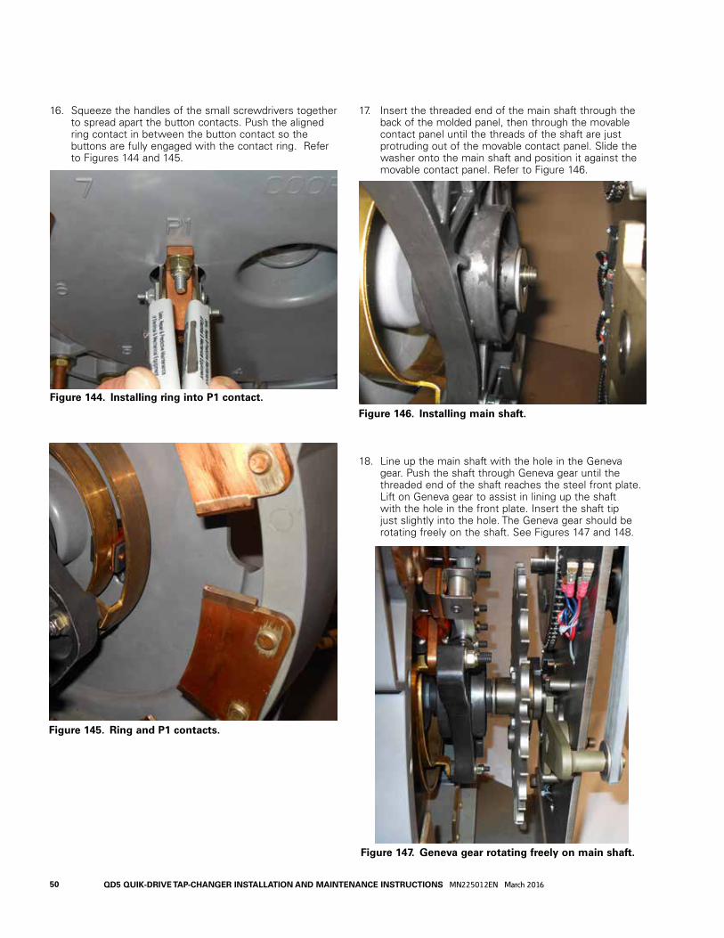
16. Squeeze the handles of the small screwdrivers together to spread apart the button contacts. Push the aligned ring contact in between the button contact so the buttons are fully engaged with the contact ring. Refer to Figures 144 and 145.
17. Insert the threaded end of the main shaft through the back of the molded panel, then through the movable contact panel until the threads of the shaft are just protruding out of the movable contact panel. Slide the washer onto the main shaft and position it against the movable contact panel. Refer to Figure 146.
18. Line up the main shaft with the hole in the Geneva gear. Push the shaft through Geneva gear until the threaded end of the shaft reaches the steel front plate. Lift on Geneva gear to assist in lining up the shaft with the hole in the front plate. Insert the shaft tip just slightly into the hole. The Geneva gear should be rotating freely on the shaft. See Figures 147 and 148.
Figure 145. Ring and P1 contacts.
Figure 144. Installing ring into P1 contact.
Figure 147. Geneva gear rotating freely on main shaft.
Figure 146. Installing main shaft.
50 QD5 QUIK-DRIVE TAP-CHANGER INSTALLATION AND MAINTENANCE INSTRUCTIONS MN225012EN March 2016
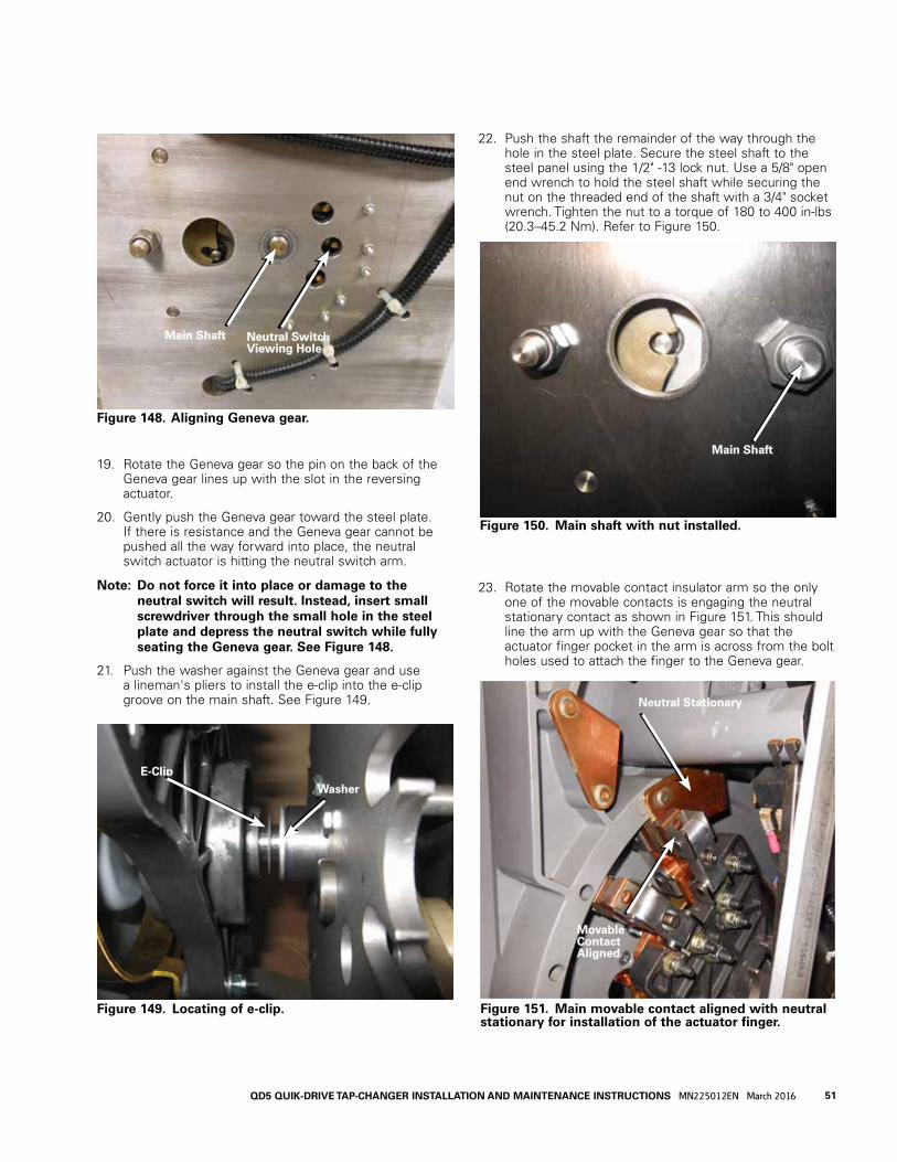
19. Rotate the Geneva gear so the pin on the back of the Geneva gear lines up with the slot in the reversing actuator.
20. Gently push the Geneva gear toward the steel plate. If there is resistance and the Geneva gear cannot be pushed all the way forward into place, the neutral switch actuator is hitting the neutral switch arm.
otee:N Do not force it into place or damage to the neutral switch will result. Instead, insert small screwdriver through the small hole in the steel plate and depress the neutral switch while fully seating the Geneva gear. See Figure 148.
21. Push the washer against the Geneva gear and use a lineman's pliers to install the e-clip into the e-clip groove on the main shaft. See Figure 149.
Figure 148. Aligning Geneva gear.
Figure 149. Locating of e-clip.
E-Clip
Washer
22. Push the shaft the remainder of the way through the hole in the steel plate. Secure the steel shaft to the steel panel using the 1/2" -13 lock nut. Use a 5/8" open end wrench to hold the steel shaft while securing the nut on the threaded end of the shaft with a 3/4" socket wrench. Tighten the nut to a torque of 180 to 400 in-lbs (20.3–45.2 Nm). Refer to Figure 150.
23. Rotate the movable contact insulator arm so the only one of the movable contacts is engaging the neutral stationary contact as shown in Figure 151. This should line the arm up with the Geneva gear so that the actuator finger pocket in the arm is across from the bolt holes used to attach the finger to the Geneva gear.
Figure 150. Main shaft with nut installed.
Main Shaft
Main Shaft Neutral Switch Viewing Hole
Figure 151. Main movable contact aligned with neutral stationary for installation of the actuator finger.
Neutral Stationary
Movable Contact Aligned
51QD5 QUIK-DRIVE TAP-CHANGER INSTALLATION AND MAINTENANCE INSTRUCTIONS MN225012EN March 2016
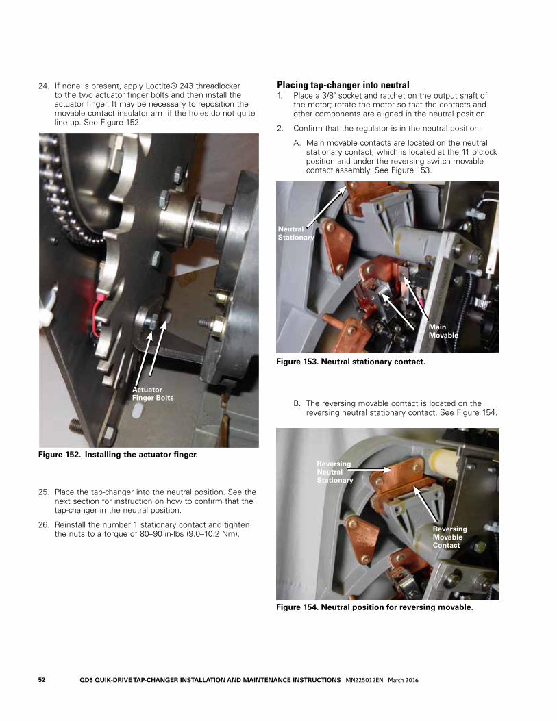
Placing tap-changer into neutral1. Place a 3/8" socket and ratchet on the output shaft of
the motor; rotate the motor so that the contacts and other components are aligned in the neutral position
2. Confirm that the regulator is in the neutral position.
A. Main movable contacts are located on the neutral stationary contact, which is located at the 11 o’clock position and under the reversing switch movable contact assembly. See Figure 153.
B. The reversing movable contact is located on the reversing neutral stationary contact. See Figure 154.
24. If none is present, apply Loctite® 243 threadlocker to the two actuator finger bolts and then install the actuator finger. It may be necessary to reposition the movable contact insulator arm if the holes do not quite line up. See Figure 152.
25. Place the tap-changer into the neutral position. See the next section for instruction on how to confirm that the tap-changer in the neutral position.
26. Reinstall the number 1 stationary contact and tighten the nuts to a torque of 80–90 in-lbs (9.0–10.2 Nm).
Figure 153. Neutral stationary contact.
Neutral Stationary
Main Movable
Figure 152. Installing the actuator finger.
Actuator Finger Bolts
Figure 154. Neutral position for reversing movable.
Reversing MovableContact
Reversing Neutral Stationary
52 QD5 QUIK-DRIVE TAP-CHANGER INSTALLATION AND MAINTENANCE INSTRUCTIONS MN225012EN March 2016

C. The pinion cam is pointing to the right over the holding switch actuator. See Figure 155.
Figure 155. Neutral position for position indicator pinion cam and holding switch.
Pinion Cam
Holding Switch Actuator
53QD5 QUIK-DRIVE TAP-CHANGER INSTALLATION AND MAINTENANCE INSTRUCTIONS MN225012EN March 2016

This page is intentionally left blank.
54 QD5 QUIK-DRIVE TAP-CHANGER INSTALLATION AND MAINTENANCE INSTRUCTIONS MN225012EN March 2016

This page is intentionally left blank.
55QD5 QUIK-DRIVE TAP-CHANGER INSTALLATION AND MAINTENANCE INSTRUCTIONS MN225012EN March 2016

Eaton1000 Eaton BoulevardCleveland, OH 44122United StatesEaton.com
Eaton’s Cooper Power Systems Division2300 Badger DriveWaukesha, WI 53188Eaton.com/cooperpowerseries
© 2016 EatonAll Rights ReservedPrinted in USAPublication No. MN2225012ENMarch 2016
!SAFETYFOR LIFE
Eaton is a registered trademark.
All trademarks are property of their respective owners.
For Eaton's Cooper Power series product information call 1-877-277-4636 or visit: www.eaton.com/cooperpowerseries.


