Do you have an your customer protocol? www.adfweb.com?Product=HD67003
Do you need to choose a device? do you want help? www.adfweb.com?Cmd=helpme
User Manual
Industrial Electronic Devices
ADFweb.com S.r.l.
User Manual Modbus Master / MQTT
Document code: MN67933_ENG Revision 1.101 Page 2 of 45
INDEX:
Page
INDEX 2
UPDATED DOCUMENTATION 2
REVISION LIST 2
WARNING 2
TRADEMARKS 2
SECURITY ALERT 3
EXAMPLE OF CONNECTION 4
CONNECTION SCHEME 5
CHARACTERISTICS 11
CONFIGURATION 11
POWER SUPPLY 12
FUNCTION MODES 13
LEDS 14
RS232 15
RS485 16
ETHERNET 17
GPRS 17
USE OF COMPOSITOR SW67933 18
NEW CONFIGURATION / OPEN CONFIGURATION 19
SOFTWARE OPTIONS 20
SET COMMUNICATION 22
MQTT SET TOPIC (Synchronous Mode) 29
MQTT SET TOPIC (Asynchronous Mode) 30
MODBUS SET ACCESS (Synchronous Mode) 33
MODBUS SET ACCESS (Asynchronous Mode) 34
UPDATE DEVICE 36
TEMPLATE STRING: DEFINITION OF MQTT PAYLOAD
38
MODBUS WRITING WITH SYNCHRONOUS MODE 40
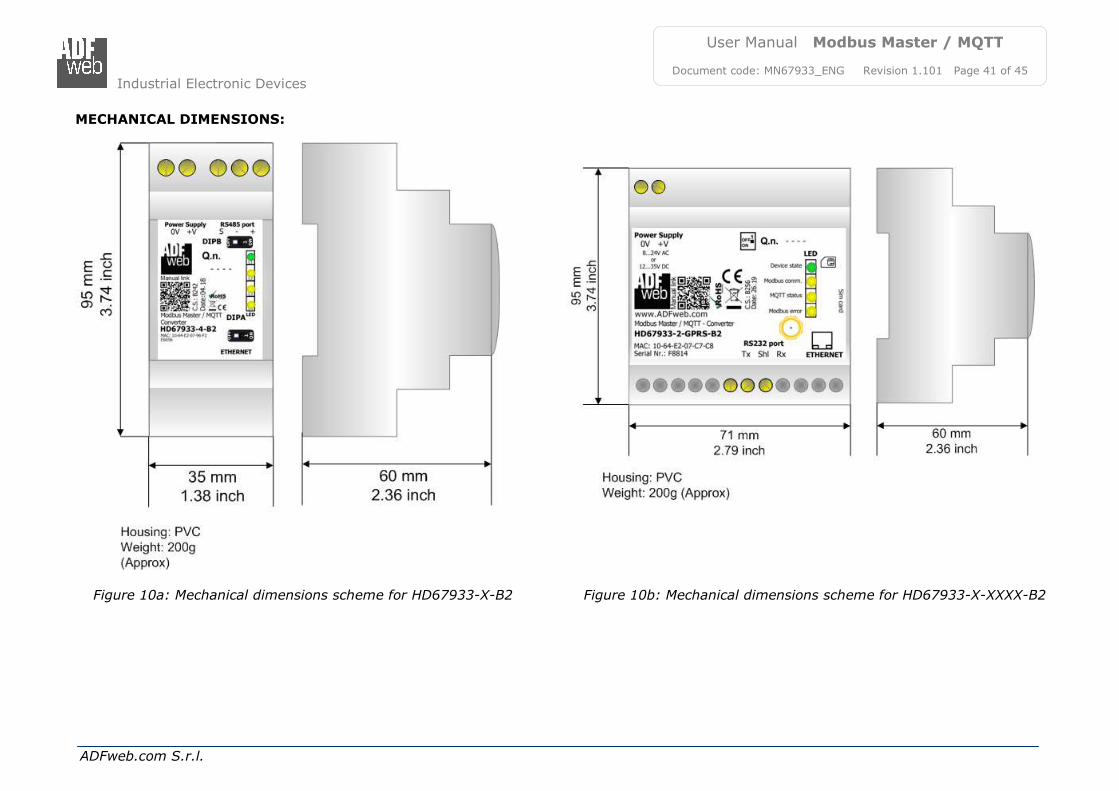
MECHANICAL DIMENSIONS 41
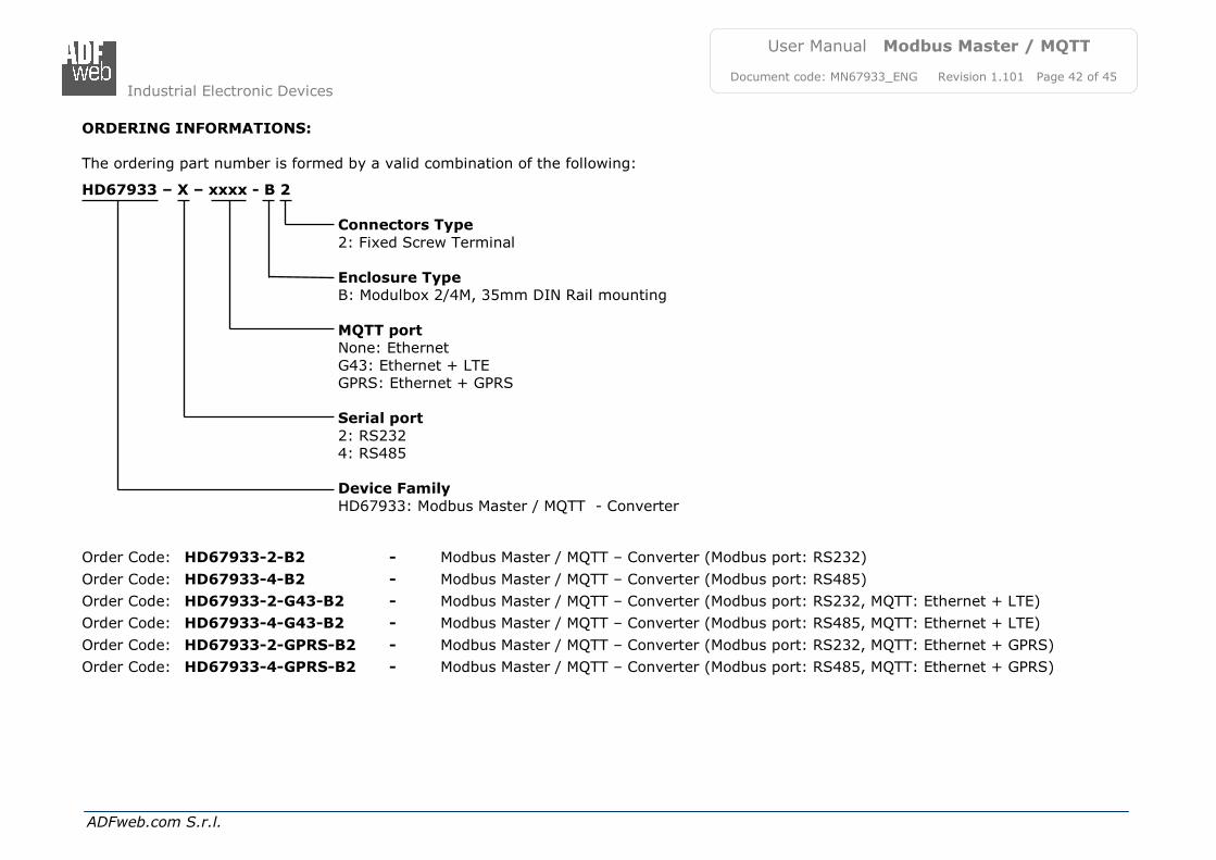
ORDERING INFORMATIONS 42
ACCESSORIES 43
DISCLAIMER 44
OTHER REGULATIONS AND STANDARDS 44
WARRANTIES AND TECHNICAL SUPPORT 45
RETURN POLICY 45
UPDATED DOCUMENTATION:
Dear customer, we thank you for your attention and we remind you that you need to check that the following document is:
Updated
Related to the product you own To obtain the most recently updated document, note the “document code” that appears at the top right-hand corner of each page of this document. With this “Document Code” go to web page www.adfweb.com/download/ and search for the corresponding code on the page. Click on the proper
“Document Code” and download the updates.
REVISION LIST:
WARNING:
ADFweb.com reserves the right to change information in this manual about our product without warning. ADFweb.com is not responsible for any error this manual may contain.
TRADEMARKS:
All trademarks mentioned in this document belong to their respective owners.
Revision Date Author Chapter Description
1.000 05/12/2017 Ff All First release version
1.001 23/03/2018 Ff All Revision
1.100 20/06/2019 Ff All Revision
1.101 28/05/2021 Ff All Revision
Industrial Electronic Devices
ADFweb.com S.r.l.
User Manual Modbus Master / MQTT
Document code: MN67933_ENG Revision 1.101 Page 3 of 45
SECURITY ALERT:
GENERAL INFORMATION
To ensure safe operation, the device must be operated according to the instructions in the manual. When using the device, legal and safety regulation are required for each individual application. The same applies also when using accessories.
INTENDED USE
Machines and systems must be designed so the faulty conditions do not lead to a dangerous situation for the operator (i.e. independent limit switches, mechanical interlocks, etc.).
QUALIFIED PERSONNEL
The device can be used only by qualified personnel, strictly in accordance with the specifications. Qualified personnel are persons who are familiar with the installation, assembly, commissioning and operation of this equipment and
who have appropriate qualifications for their job.
RESIDUAL RISKS
The device is state-of-the-art and is safe. The instruments can represent a potential hazard if they are inappropriately installed and operated by untrained personnel. These instructions refer to residual risks with the following symbol:
This symbol indicates that non-observance of the safety instructions is a danger for people that could lead to serious injury or
death and / or the possibility of damage.
CE CONFORMITY The declaration is made by our company. You can send an email to [email protected] or give us a call if you need it.
Industrial Electronic Devices
ADFweb.com S.r.l.
User Manual Modbus Master / MQTT
Document code: MN67933_ENG Revision 1.101 Page 4 of 45
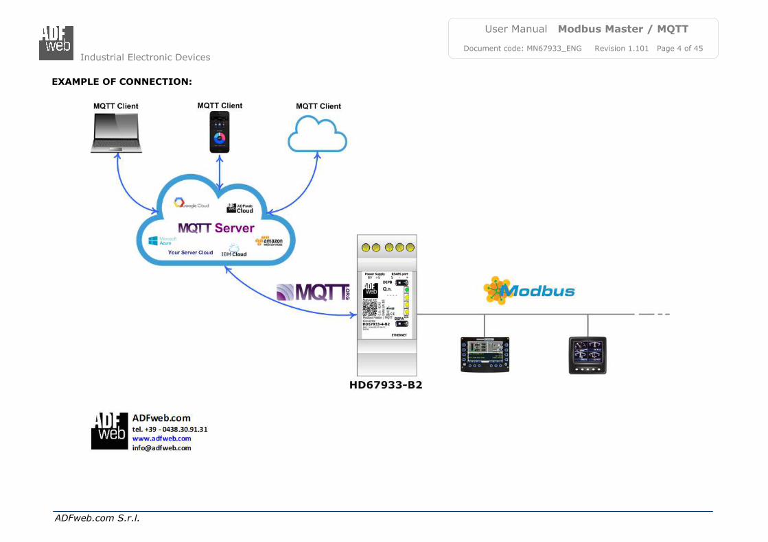
EXAMPLE OF CONNECTION:
Industrial Electronic Devices
ADFweb.com S.r.l.
User Manual Modbus Master / MQTT
Document code: MN67933_ENG Revision 1.101 Page 5 of 45
CONNECTION SCHEME:
Figure 1a: Connection scheme for HD67933-2-B2
Industrial Electronic Devices
ADFweb.com S.r.l.
User Manual Modbus Master / MQTT
Document code: MN67933_ENG Revision 1.101 Page 6 of 45
Figure 1b: Connection scheme for HD67933-4-B2
Industrial Electronic Devices
ADFweb.com S.r.l.
User Manual Modbus Master / MQTT
Document code: MN67933_ENG Revision 1.101 Page 7 of 45
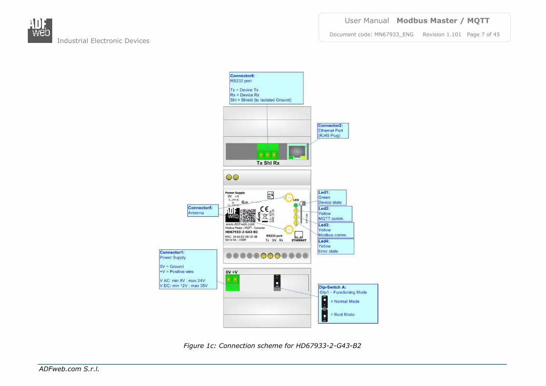
Figure 1c: Connection scheme for HD67933-2-G43-B2
Industrial Electronic Devices
ADFweb.com S.r.l.
User Manual Modbus Master / MQTT
Document code: MN67933_ENG Revision 1.101 Page 8 of 45
Figure 1d: Connection scheme for HD67933-4-G43-B2
Industrial Electronic Devices
ADFweb.com S.r.l.
User Manual Modbus Master / MQTT
Document code: MN67933_ENG Revision 1.101 Page 9 of 45
Figure 1e: Connection scheme for HD67933-2-GPRS-B2
Industrial Electronic Devices
ADFweb.com S.r.l.
User Manual Modbus Master / MQTT
Document code: MN67933_ENG Revision 1.101 Page 10 of 45
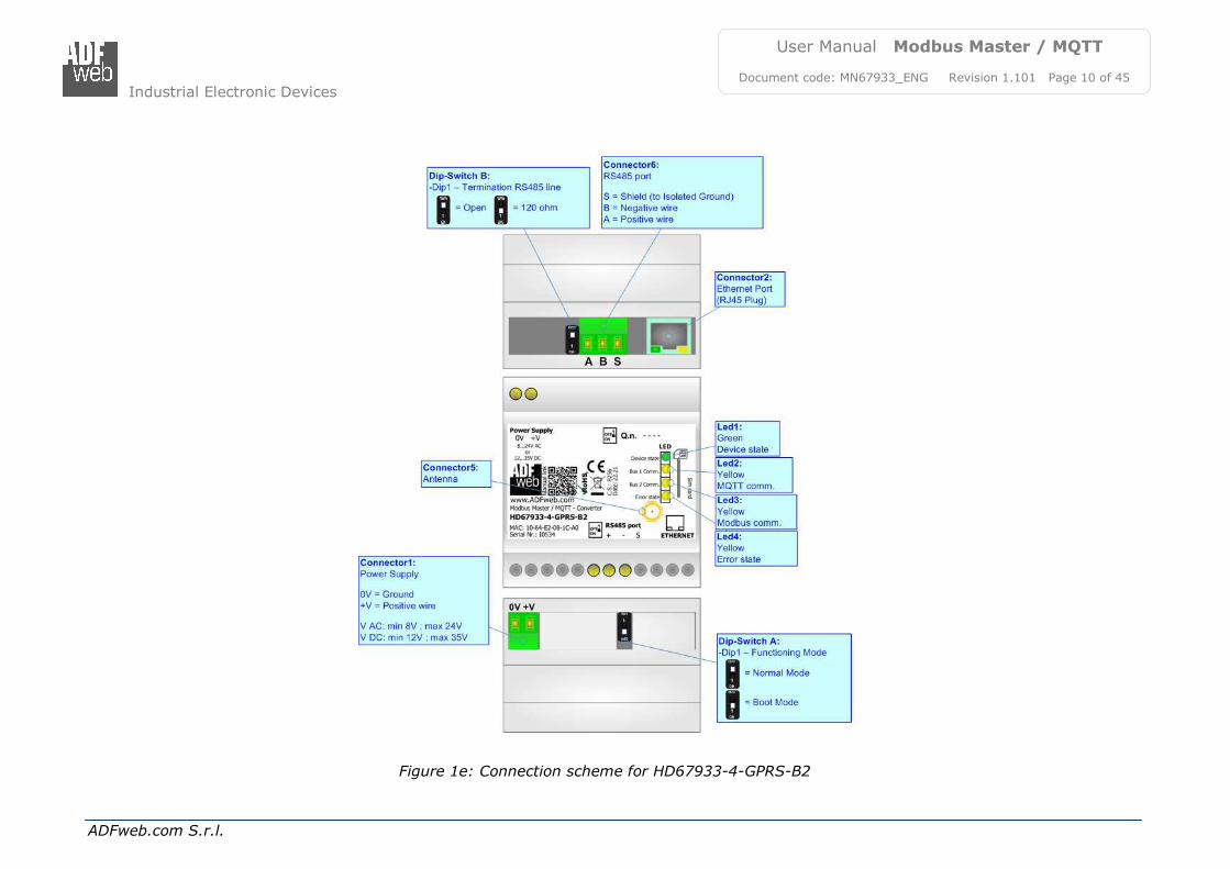
Figure 1e: Connection scheme for HD67933-4-GPRS-B2
Industrial Electronic Devices
ADFweb.com S.r.l.
User Manual Modbus Master / MQTT
Document code: MN67933_ENG Revision 1.101 Page 11 of 45
CHARACTERISTICS:
The HD67933-B2 is a Modbus Master / MQTT Converter.
It allows the following characteristics:
Electrical isolation between MQTT and Modbus;
Mountable on 35mm Rail DIN;
Wide power supply input range: 18…35V DC and 8…24V AC;
Wide temperature range: -40°C / 85°C [-40°F / +185°F].
CONFIGURATION:
You need Compositor SW67933 software on your PC in order to perform the following:
Define the parameter of MQTT;
Define the parameter of Modbus line;
Define which Modbus variables are sent to MQTT Server;
Define which Modbus variables are written by MQTT Server;
Update the device.
Industrial Electronic Devices
ADFweb.com S.r.l.
User Manual Modbus Master / MQTT
Document code: MN67933_ENG Revision 1.101 Page 12 of 45
POWER SUPPLY:
The devices can be powered at 8…24V AC and 12…35V DC. For more details see the two tables below.
VAC VDC
Vmin Vmax Vmin Vmax
8V 24V 12V 35V
Consumption at 24V DC:
Device Consumption [W/VA]
HD67933-B2 3.5
HD67933-x-B2
HD67933-x-G43-B2 HD67933-x-GPRS-B2
Caution: Not reverse the polarity power
Industrial Electronic Devices
ADFweb.com S.r.l.
User Manual Modbus Master / MQTT
Document code: MN67933_ENG Revision 1.101 Page 13 of 45
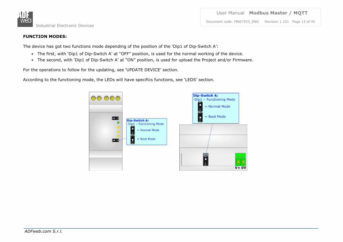
FUNCTION MODES:
The device has got two functions mode depending of the position of the ‘Dip1 of Dip-Switch A’:
The first, with ‘Dip1 of Dip-Switch A’ at “OFF” position, is used for the normal working of the device.
The second, with ‘Dip1 of Dip-Switch A’ at “ON” position, is used for upload the Project and/or Firmware.
For the operations to follow for the updating, see ‘UPDATE DEVICE’ section. According to the functioning mode, the LEDs will have specifics functions, see ‘LEDS’ section.
Industrial Electronic Devices
ADFweb.com S.r.l.
User Manual Modbus Master / MQTT
Document code: MN67933_ENG Revision 1.101 Page 14 of 45
LEDS:
The device has got five LEDs that are used to give information of the functioning status. The various meanings of the LEDs are described in the table below.
LED Normal Mode Boot Mode
1: Device State (green) Blinks slowly (~1Hz) Blinks quickly: Boot state
Blinks very slowly (~0.5Hz): update in progress
2: MQTT communication (yellow)
Blinks when MQTT communication is running Blinks quickly: Boot state
Blinks very slowly (~0.5Hz): update in progress
3: Modbus communication
(yellow) Blinks when Modbus communication is running
Blinks quickly: Boot state
Blinks very slowly (~0.5Hz): update in progress
4:Modbus error (yellow) Turns ON when an error occurs Blinks quickly: Boot state
Blinks very slowly (~0.5Hz): update in progress
5: Ethernet Link (green) ON: Ethernet cable connected
OFF: Ethernet cable disconnected
ON: Ethernet cable connected
OFF: Ethernet cable disconnected
Industrial Electronic Devices
ADFweb.com S.r.l.
User Manual Modbus Master / MQTT
Document code: MN67933_ENG Revision 1.101 Page 15 of 45
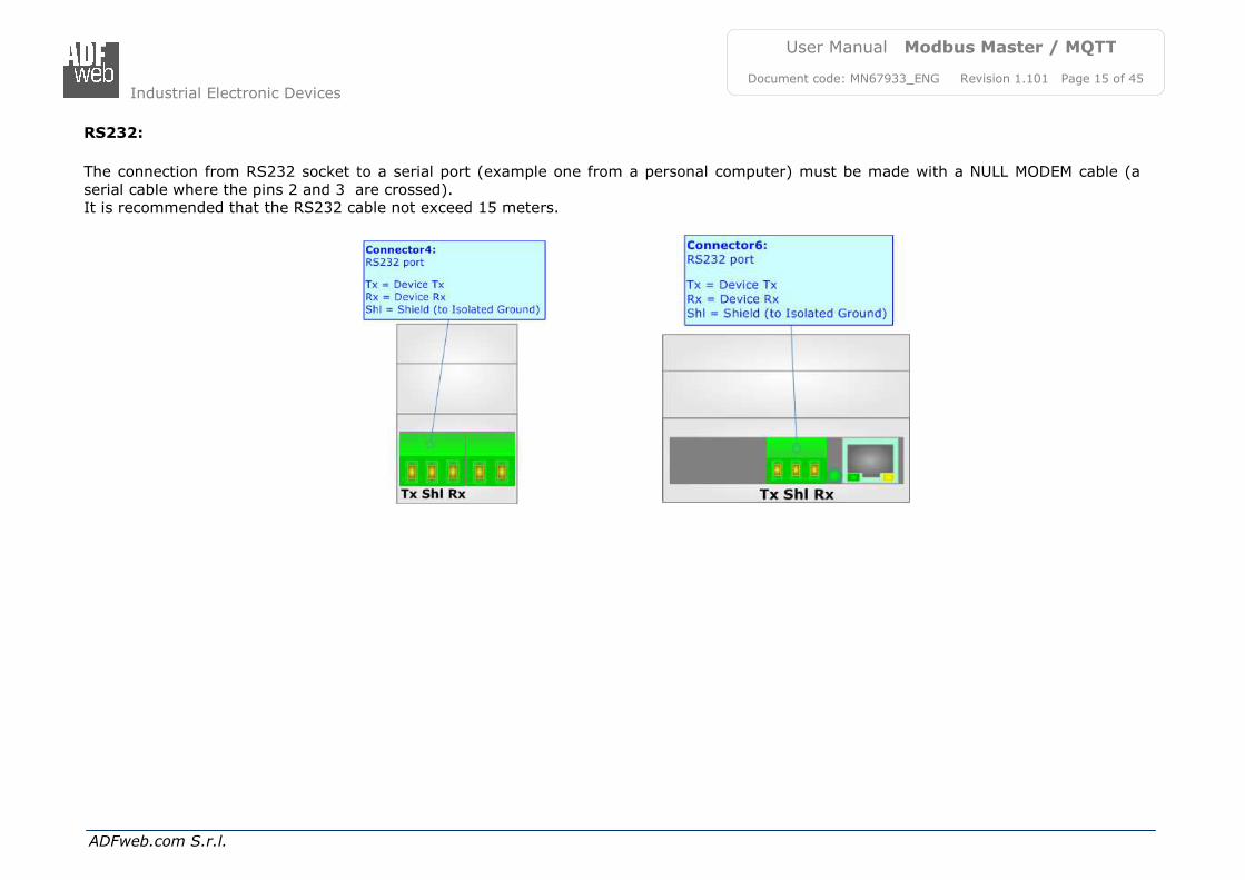
RS232:
The connection from RS232 socket to a serial port (example one from a personal computer) must be made with a NULL MODEM cable (a
serial cable where the pins 2 and 3 are crossed). It is recommended that the RS232 cable not exceed 15 meters.
Industrial Electronic Devices
ADFweb.com S.r.l.
User Manual Modbus Master / MQTT
Document code: MN67933_ENG Revision 1.101 Page 16 of 45
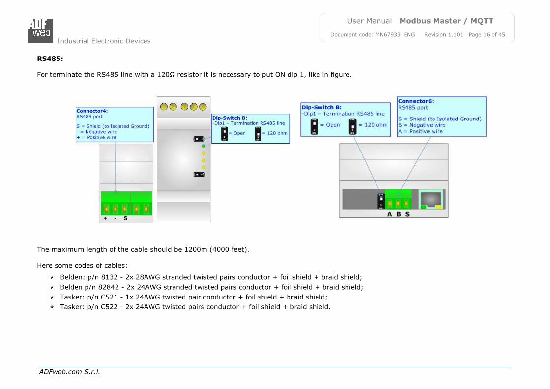
RS485:
For terminate the RS485 line with a 120Ω resistor it is necessary to put ON dip 1, like in figure.
The maximum length of the cable should be 1200m (4000 feet). Here some codes of cables:
Document code: MN67933_ENG Revision 1.101 Page 17 of 45
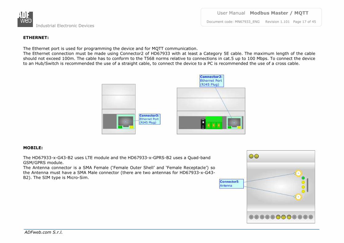
ETHERNET:
The Ethernet port is used for programming the device and for MQTT communication. The Ethernet connection must be made using Connector2 of HD67933 with at least a Category 5E cable. The maximum length of the cable
should not exceed 100m. The cable has to conform to the T568 norms relative to connections in cat.5 up to 100 Mbps. To connect the device to an Hub/Switch is recommended the use of a straight cable, to connect the device to a PC is recommended the use of a cross cable.
MOBILE:
The HD67933-x-G43-B2 uses LTE module and the HD67933-x-GPRS-B2 uses a Quad-band GSM/GPRS module.
The Antenna connector is a SMA Female (‘Female Outer Shell’ and ‘Female Receptacle’) so the Antenna must have a SMA Male connector (there are two antennas for HD67933-x-G43-B2). The SIM type is Micro-Sim.
Industrial Electronic Devices
ADFweb.com S.r.l.
User Manual Modbus Master / MQTT
Document code: MN67933_ENG Revision 1.101 Page 18 of 45
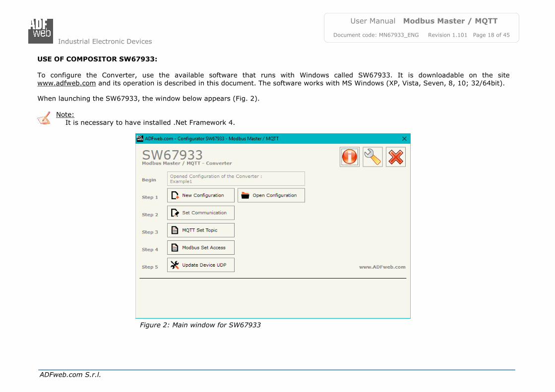
USE OF COMPOSITOR SW67933:
To configure the Converter, use the available software that runs with Windows called SW67933. It is downloadable on the site www.adfweb.com and its operation is described in this document. The software works with MS Windows (XP, Vista, Seven, 8, 10; 32/64bit).
When launching the SW67933, the window below appears (Fig. 2).
Note: It is necessary to have installed .Net Framework 4.
Figure 2: Main window for SW67933
Industrial Electronic Devices
ADFweb.com S.r.l.
User Manual Modbus Master / MQTT
Document code: MN67933_ENG Revision 1.101 Page 19 of 45
NEW CONFIGURATION / OPEN CONFIGURATION:
The “New Configuration” button creates the folder which contains the entire device’s configuration.
A device’s configuration can also be imported or exported:
To clone the configurations of a Programmable “Modbus Master / MQTT - Converter” in order to configure another device in the same manner, it is necessary to maintain the folder and all its contents;
To clone a project in order to obtain a different version of the project, it is sufficient to duplicate the project folder with another name and open the new folder with the button “Open Configuration”.
Industrial Electronic Devices
ADFweb.com S.r.l.
User Manual Modbus Master / MQTT
Document code: MN67933_ENG Revision 1.101 Page 20 of 45
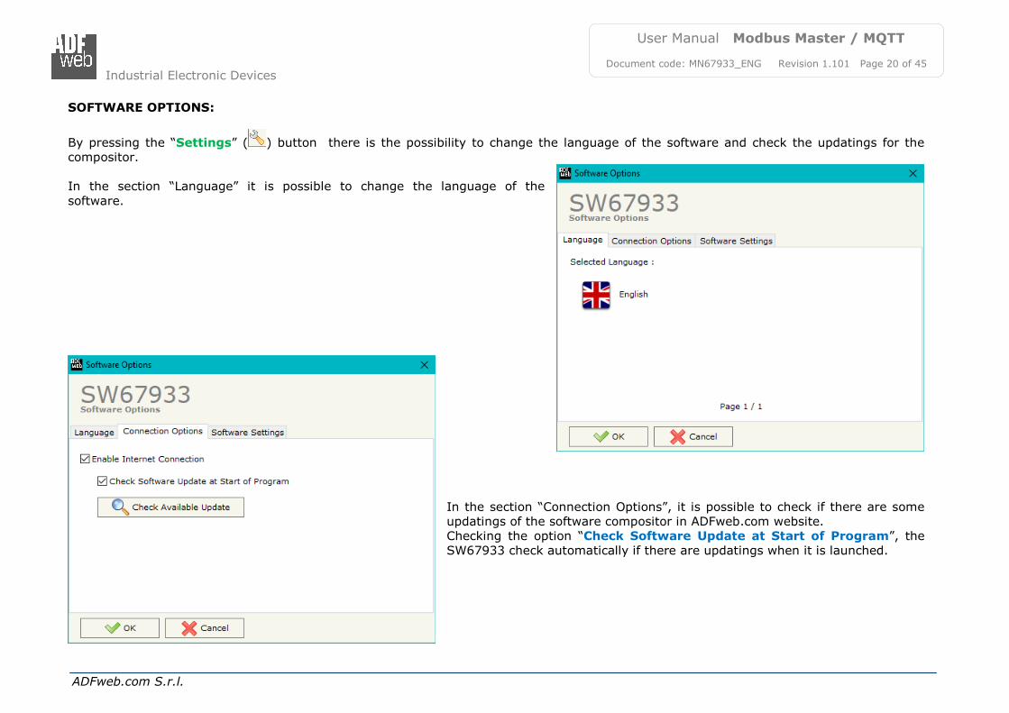
SOFTWARE OPTIONS:
By pressing the “Settings” ( ) button there is the possibility to change the language of the software and check the updatings for the compositor. In the section “Language” it is possible to change the language of the
software.
In the section “Connection Options”, it is possible to check if there are some updatings of the software compositor in ADFweb.com website. Checking the option “Check Software Update at Start of Program”, the SW67933 check automatically if there are updatings when it is launched.
Industrial Electronic Devices
ADFweb.com S.r.l.
User Manual Modbus Master / MQTT
Document code: MN67933_ENG Revision 1.101 Page 21 of 45
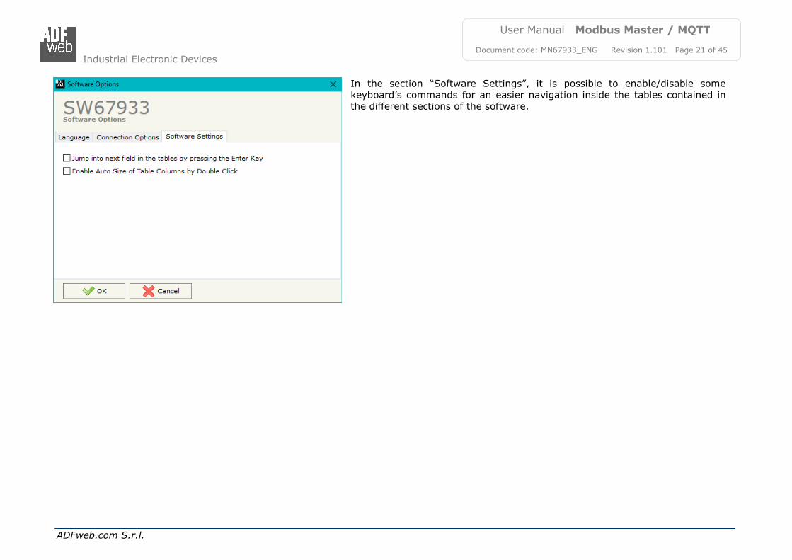
In the section “Software Settings”, it is possible to enable/disable some keyboard’s commands for an easier navigation inside the tables contained in the different sections of the software.
Industrial Electronic Devices
ADFweb.com S.r.l.
User Manual Modbus Master / MQTT
Document code: MN67933_ENG Revision 1.101 Page 22 of 45
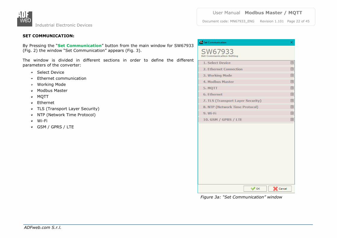
SET COMMUNICATION:
By Pressing the “Set Communication” button from the main window for SW67933 (Fig. 2) the window “Set Communication” appears (Fig. 3). The window is divided in different sections in order to define the different
parameters of the converter:
Select Device
Ethernet communication
Working Mode
Modbus Master
MQTT
Ethernet
TLS (Transport Layer Security)
NTP (Network Time Protocol)
Wi-Fi
GSM / GPRS / LTE
Figure 3a: “Set Communication” window
Industrial Electronic Devices
ADFweb.com S.r.l.
User Manual Modbus Master / MQTT
Document code: MN67933_ENG Revision 1.101 Page 23 of 45
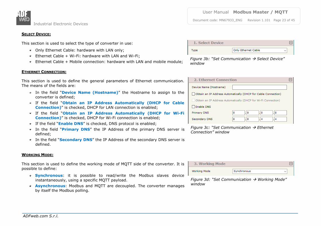
Figure 3d: “Set Communication Working Mode” window
Figure 3b: “Set Communication Select Device” window
Figure 3c: “Set Communication Ethernet Connection” window
SELECT DEVICE:
This section is used to select the type of converter in use:
Only Ethernet Cable: hardware with LAN only;
Ethernet Cable + Wi-Fi: hardware with LAN and Wi-Fi;
Ethernet Cable + Mobile connection: hardware with LAN and mobile module;
ETHERNET CONNECTION:
This section is used to define the general parameters of Ethernet communication.
The means of the fields are:
In the field “Device Name (Hostname)” the Hostname to assign to the converter is defined;
If the field “Obtain an IP Address Automatically (DHCP for Cable
Connection)” is checked, DHCP for LAN connection is enabled;
If the field “Obtain an IP Address Automatically (DHCP for Wi-Fi
Connection)” is checked, DHCP for Wi-Fi connection is enabled;
If the field “Enable DNS” is checked, DNS protocol is enabled;
In the field “Primary DNS” the IP Address of the primary DNS server is defined;
In the field “Secondary DNS” the IP Address of the secondary DNS server is
defined.
WORKING MODE:
This section is used to define the working mode of MQTT side of the converter. It is possible to define:
Synchronous: it is possible to read/write the Modbus slaves device
instantaneously, using a specific MQTT payload.
Asynchronous: Modbus and MQTT are decoupled. The converter manages by itself the Modbus polling.
Industrial Electronic Devices
ADFweb.com S.r.l.
User Manual Modbus Master / MQTT
Document code: MN67933_ENG Revision 1.101 Page 24 of 45
Figure 3e: “Set Communication Modbus Master”
window
MODBUS MASTER:
This section is used to define the main parameters of Modbus line. The means of the fields are:
In the field “Serial” the serial port to use is defined (RS232 or RS485);
In the field “Baudrate” the baudrate for the serial line is defined;
In the field “Parity” the parity of the serial line is defined;
In the field “Stop Bits” the number of Stop Bits of the serial line is defined;
In the field “TimeOut (ms)” the maximum time that the converter attends
for the answer from the Slave interrogated is defined;
In the field “Cyclic Delay (ms)” the delay (idle time) between two Modbus requests is defined.
Industrial Electronic Devices
ADFweb.com S.r.l.
User Manual Modbus Master / MQTT
Document code: MN67933_ENG Revision 1.101 Page 25 of 45
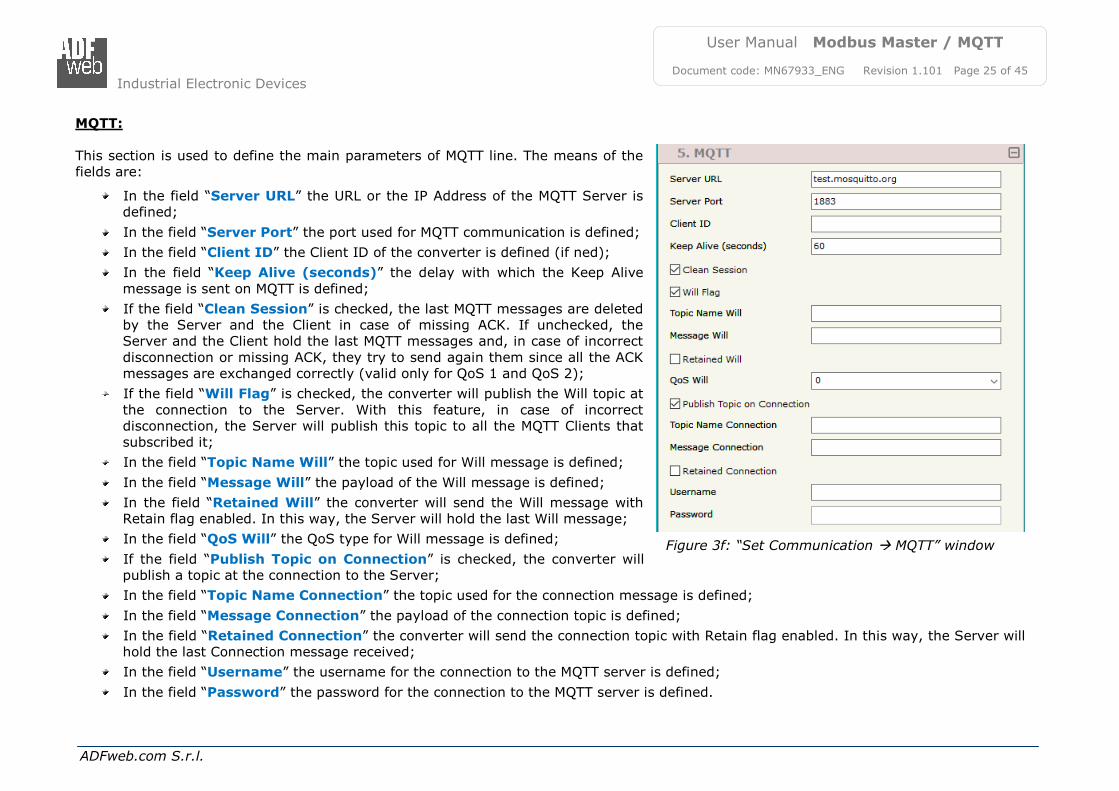
Figure 3f: “Set Communication MQTT” window
MQTT:
This section is used to define the main parameters of MQTT line. The means of the fields are:
In the field “Server URL” the URL or the IP Address of the MQTT Server is defined;
In the field “Server Port” the port used for MQTT communication is defined;
In the field “Client ID” the Client ID of the converter is defined (if ned);
In the field “Keep Alive (seconds)” the delay with which the Keep Alive
message is sent on MQTT is defined;
If the field “Clean Session” is checked, the last MQTT messages are deleted by the Server and the Client in case of missing ACK. If unchecked, the Server and the Client hold the last MQTT messages and, in case of incorrect
disconnection or missing ACK, they try to send again them since all the ACK messages are exchanged correctly (valid only for QoS 1 and QoS 2);
If the field “Will Flag” is checked, the converter will publish the Will topic at
the connection to the Server. With this feature, in case of incorrect disconnection, the Server will publish this topic to all the MQTT Clients that subscribed it;
In the field “Topic Name Will” the topic used for Will message is defined;
In the field “Message Will” the payload of the Will message is defined;
In the field “Retained Will” the converter will send the Will message with Retain flag enabled. In this way, the Server will hold the last Will message;
In the field “QoS Will” the QoS type for Will message is defined;
If the field “Publish Topic on Connection” is checked, the converter will publish a topic at the connection to the Server;
In the field “Topic Name Connection” the topic used for the connection message is defined;
In the field “Message Connection” the payload of the connection topic is defined;
In the field “Retained Connection” the converter will send the connection topic with Retain flag enabled. In this way, the Server will hold the last Connection message received;
In the field “Username” the username for the connection to the MQTT server is defined;
In the field “Password” the password for the connection to the MQTT server is defined.
Industrial Electronic Devices
ADFweb.com S.r.l.
User Manual Modbus Master / MQTT
Document code: MN67933_ENG Revision 1.101 Page 26 of 45
Figure 3g: “Set Communication Ethernet” window
Figure 3h: “Set Communication TLS” window
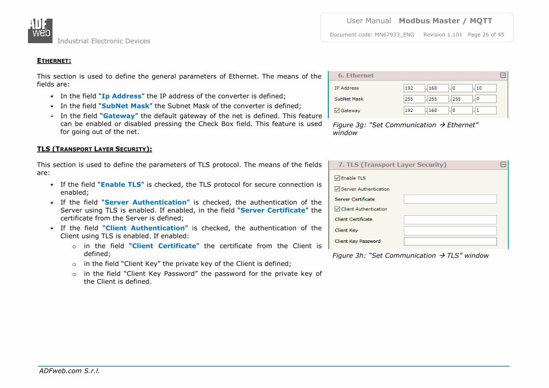
ETHERNET:
This section is used to define the general parameters of Ethernet. The means of the fields are:
In the field “Ip Address” the IP address of the converter is defined;
In the field “SubNet Mask” the Subnet Mask of the converter is defined;
In the field “Gateway” the default gateway of the net is defined. This feature can be enabled or disabled pressing the Check Box field. This feature is used for going out of the net.
TLS (TRANSPORT LAYER SECURITY):
This section is used to define the parameters of TLS protocol. The means of the fields
are:
If the field “Enable TLS” is checked, the TLS protocol for secure connection is enabled;
If the field “Server Authentication” is checked, the authentication of the
Server using TLS is enabled. If enabled, in the field “Server Certificate” the certificate from the Server is defined;
If the field “Client Authentication” is checked, the authentication of the Client using TLS is enabled. If enabled:
o in the field “Client Certificate” the certificate from the Client is defined;
o in the field “Client Key” the private key of the Client is defined;
o in the field “Client Key Password” the password for the private key of the Client is defined.
Industrial Electronic Devices
ADFweb.com S.r.l.
User Manual Modbus Master / MQTT
Document code: MN67933_ENG Revision 1.101 Page 27 of 45
Figure 3i: “Set Communication NTP” window
Figure 3j: “Set Communication Wi-Fi” window
NTP (NETWORK TIME PROTOCOL):
This section is used to define the parameters of NTP protocol. The means of the fields are:
In the field “Server URL” the URL or the IP Address of the NTP Server is defined;
In the field “Poll Time (seconds)” the polling time for the time synchronization is defined.
WI-FI:
This section is used to define the general parameters of Wi-Fi. It is possible to defined the type of Wi-Fi communication:
Access Point;
Station.
The means of the fields for Access Point configuration are:
In the field “IP Address” the IP address of the converter is defined;
In the field “Subnet Mask” the SubNet Mask of the converter is defined;
In the field “GATEWAY” the default gateway of the net is defined. This feature can be enabled or disabled pressing the Check Box field. This feature is used for going out of the net;
In the field “SSID” the name of the Wi-Fi network to create is defined;
In the field “Password” the password used for Wi-Fi connection is defined;
In the field “Secure Type” the type of security protocol used by the Wi-Fi
network is defined;
If the field “Enable DHCP” is checked, the converter acts as DHCP Server for the Clients connected. If the option is enabled, in the fields “DHCP First IP
Address” and “DHCP SUBNET Mask” the IP Addresses range used for DHCP
is defined. In the field “Lease Time (seconds)” the required time for the renewing of the IP Address assigned to the Client is defined;
In the field “Max Client” the maximum number of Wi-Fi Clients accepted is
defined;
In the field “Channel” the channel for Wi-Fi communication is defined.
Industrial Electronic Devices
ADFweb.com S.r.l.
User Manual Modbus Master / MQTT
Document code: MN67933_ENG Revision 1.101 Page 28 of 45
Figure 3k: “Set Communication Wi-Fi” window
Figure 3l: “Set Communication GSM / GPRS”
window
The means of the fields for Station configuration are:
In the field “IP Address” (OPC UA Client) the IP address for OPC UA side of
the converter is defined;
In the field “Subnet Mask” (OPC UA Client) the SubNet Mask for OPC UA side of the converter is defined;
In the field “GATEWAY” (OPC UA Client) the default gateway of the OPC UA
net is defined. This feature can be enabled or disabled pressing the Check Box field. This feature is used for going out of the net;
In the field “IP Address” (MQTT) the IP address for MQTT side of the
converter is defined;
In the field “Subnet Mask” (MQTT) the SubNet Mask for MQTT side of the converter is defined;
In the field “GATEWAY” (MQTT) the default gateway of
the MQTT net is defined. This feature can be enabled or disabled pressing the Check Box field. This feature is used for going out of the net;
In the field “SSID” the name of the Wi-Fi network to connect is defined;
In the field “Password” the password used to connect to the Wi-Fi network is defined.
GSM / GPRS / LTE:
This section is used to define the parameters of mobile connection. The means of
the fields are:
In the field “PIN” the PIN for the SIM card (if ned) is defined;
In the field “APN” the APN for the mobile operator used is defined;
In the filed “Authentication Type” the type of authentication to the mobile network is defined;
In the field “Username” the username for the authentication is defined;
In the field “Password” the password for the authentication is defined.
Industrial Electronic Devices
ADFweb.com S.r.l.
User Manual Modbus Master / MQTT
Document code: MN67933_ENG Revision 1.101 Page 29 of 45
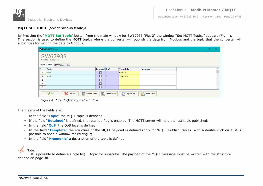
Figure 4: “Set MQTT Topics” window
MQTT SET TOPIC (Synchronous Mode):
By Pressing the “MQTT Set Topic” button from the main window for SW67933 (Fig. 2) the window “Set MQTT Topics” appears (Fig. 4). This section is used to define the MQTT topics where the converter will publish the data from Modbus and the topic that the converter will subscribes for writing the data to Modbus.
The means of the fields are:
In the field “Topic” the MQTT topic is defined;
If the field “Retained” is defined, the retained flag is enabled. The MQTT server will hold the last topic published;
In the field “QoS” the QoS level is defined;
In the field “Template” the structure of the MQTT payload is defined (only for ‘MQTT Publish’ table). With a double click on it, it is possible to open a window for editing it;
In the field “Mnemonic” a description of the topic is defined.
Note: It is possible to define a single MQTT topic for subscribe. The payload of the MQTT message must be written with the structure
defined on page 38.
Industrial Electronic Devices
ADFweb.com S.r.l.
User Manual Modbus Master / MQTT
Document code: MN67933_ENG Revision 1.101 Page 30 of 45
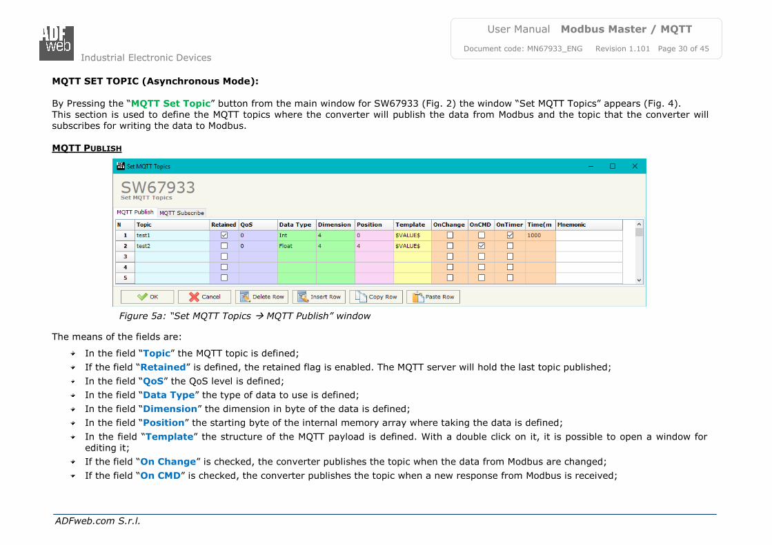
Figure 5a: “Set MQTT Topics MQTT Publish” window
MQTT SET TOPIC (Asynchronous Mode):
By Pressing the “MQTT Set Topic” button from the main window for SW67933 (Fig. 2) the window “Set MQTT Topics” appears (Fig. 4). This section is used to define the MQTT topics where the converter will publish the data from Modbus and the topic that the converter will subscribes for writing the data to Modbus.
MQTT PUBLISH
The means of the fields are:
In the field “Topic” the MQTT topic is defined;
If the field “Retained” is defined, the retained flag is enabled. The MQTT server will hold the last topic published;
In the field “QoS” the QoS level is defined;
In the field “Data Type” the type of data to use is defined;
In the field “Dimension” the dimension in byte of the data is defined;
In the field “Position” the starting byte of the internal memory array where taking the data is defined;
In the field “Template” the structure of the MQTT payload is defined. With a double click on it, it is possible to open a window for editing it;
If the field “On Change” is checked, the converter publishes the topic when the data from Modbus are changed;
If the field “On CMD” is checked, the converter publishes the topic when a new response from Modbus is received;
Industrial Electronic Devices
ADFweb.com S.r.l.
User Manual Modbus Master / MQTT
Document code: MN67933_ENG Revision 1.101 Page 31 of 45
If the field “On Timer” is checked, the converter publishes the topic cyclically with the delay defined in the field “Time (ms)”;
In the field “Mnemonic” a description of the topic is defined.
Industrial Electronic Devices
ADFweb.com S.r.l.
User Manual Modbus Master / MQTT
Document code: MN67933_ENG Revision 1.101 Page 32 of 45
If the field “Retained” is defined, the retained flag is enabled. The MQTT server will hold the last topic published;
In the field “QoS” the QoS level is defined;
In the field “Data Type” the type of data to use is defined;
In the field “Dimension” the dimension in byte of the data is defined;
In the field “Position” the starting byte of the internal memory array where placing the data is defined;
In the field “Template” the structure of the MQTT payload is defined. With a double click on it, it is possible to open a window for editing it;
In the field “Mnemonic” a description of the topic is defined.
Industrial Electronic Devices
ADFweb.com S.r.l.
User Manual Modbus Master / MQTT
Document code: MN67933_ENG Revision 1.101 Page 33 of 45
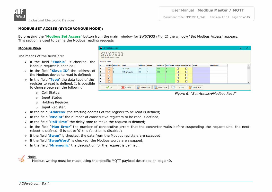
MODBUS SET ACCESS (SYNCHRONOUS MODE):
By pressing the “Modbus Set Access” button from the main window for SW67933 (Fig. 2) the window “Set Modbus Access” appears.
This section is used to define the Modbus reading requests MODBUS READ
The means of the fields are:
If the field “Enable” is checked, the Modbus request is enabled;
In the field “Slave ID” the address of the Modbus device to read is defined;
In the field “Type” the data type of the
register to read is defined. It is possible to choose between the following:
o Coil Status;
o Input Status
o Holding Register;
o Input Register.
In the field “Address” the starting address of the register to be read is defined;
In the field “NPoint” the number of consecutive registers to be read is defined;
In the field “Poll Time” the delay time to make the request is defined;
In the field “Max Error” the number of consecutive errors that the converter waits before suspending the request until the next
reboot is defined. If is set to ‘0’ this function is disabled;
If the field “Swap” is checked, the data from the Modbus registers are swapped;
If the field “SwapWord” is checked, the Modbus words are swapped;
In the field “Mnemonic” the description for the request is defined.
Note:
Modbus writing must be made using the specific MQTT payload described on page 40.
Figure 6: “Set AccessModbus Read”
window
Industrial Electronic Devices
ADFweb.com S.r.l.
User Manual Modbus Master / MQTT
Document code: MN67933_ENG Revision 1.101 Page 34 of 45
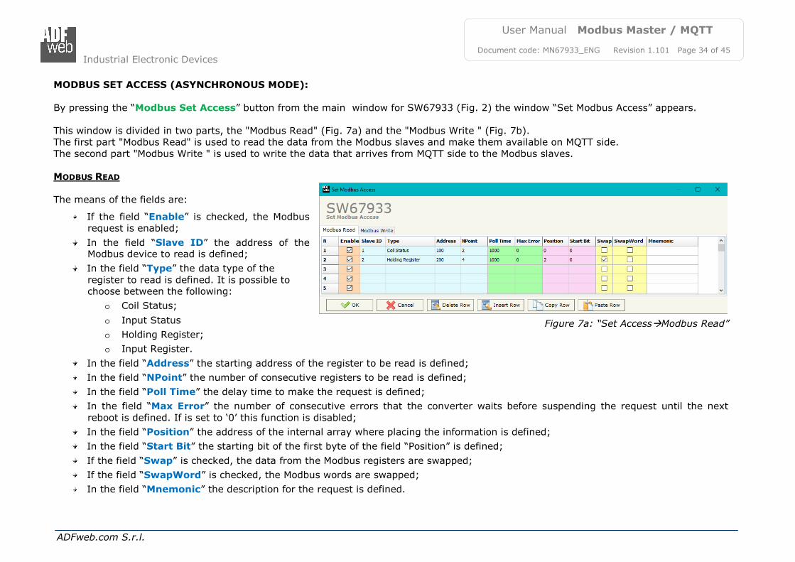
MODBUS SET ACCESS (ASYNCHRONOUS MODE):
By pressing the “Modbus Set Access” button from the main window for SW67933 (Fig. 2) the window “Set Modbus Access” appears. This window is divided in two parts, the "Modbus Read" (Fig. 7a) and the "Modbus Write " (Fig. 7b). The first part "Modbus Read" is used to read the data from the Modbus slaves and make them available on MQTT side.
The second part "Modbus Write " is used to write the data that arrives from MQTT side to the Modbus slaves. MODBUS READ
The means of the fields are:
If the field “Enable” is checked, the Modbus request is enabled;
In the field “Slave ID” the address of the Modbus device to read is defined;
In the field “Type” the data type of the
register to read is defined. It is possible to choose between the following:
o Coil Status;
o Input Status
o Holding Register;
o Input Register.
In the field “Address” the starting address of the register to be read is defined;
In the field “NPoint” the number of consecutive registers to be read is defined;
In the field “Poll Time” the delay time to make the request is defined;
In the field “Max Error” the number of consecutive errors that the converter waits before suspending the request until the next
reboot is defined. If is set to ‘0’ this function is disabled;
In the field “Position” the address of the internal array where placing the information is defined;
In the field “Start Bit” the starting bit of the first byte of the field “Position” is defined;
If the field “Swap” is checked, the data from the Modbus registers are swapped;
If the field “SwapWord” is checked, the Modbus words are swapped;
In the field “Mnemonic” the description for the request is defined.
Figure 7a: “Set AccessModbus Read”
window
Industrial Electronic Devices
ADFweb.com S.r.l.
User Manual Modbus Master / MQTT
Document code: MN67933_ENG Revision 1.101 Page 35 of 45
MODBUS WRITE
The means of the fields are:
If the field “Enable” is checked, the Modbus request is enabled;
In the field “Slave ID” the address of
the Modbus device that you have to write is defined;
In the field “Type” the data type of
the register to write is defined. It is possible to choose between the following:
o Coil Status;
o Holding Register.
In the field “Address” the start address of the register to be written is defined;
In the field “NPoint” the number of consecutive registers to be written is defined;
In the field “Poll Time” the delay time to make the request is defined;
If the field “On Change” is checked, the converter sends the writing request when the data from MQTT side change value;
If the field “On CMD” is checked, the converter sends the writing request when the data from MQTT is received;
In the field “Max Error” the number of consecutive errors that the converter waits before suspending the request until the next reboot is defined. If is set to ‘0’ this function is disabled;
In the field “Position” the address of the internal array where taking the information is defined;
In the field “Start Bit” the starting bit of the first byte of the field “Position” is defined;
If the field “Swap” is checked, the data written the Modbus registers are swapped;
If the field “SwapWord” is checked, the Modbus words are swapped;
In the field “Mnemonic” the description for the request is defined.
Figure 7b: “Set AccessModbus Write” window
Industrial Electronic Devices
ADFweb.com S.r.l.
User Manual Modbus Master / MQTT
Document code: MN67933_ENG Revision 1.101 Page 36 of 45
UPDATE DEVICE:
By pressing the “Update Device” button, it is possible to load the created Configuration into the device; and also the Firmware, if necessary. This by using the Ethernet port.
If you don’t know the actual IP address of the device you have to use this procedure:
Turn OFF the Device;
Put Dip1 of ‘Dip-Switch A’ in ON position;
Turn ON the device
Connect the Ethernet cable;
Insert the IP “192.168.2.205”;
Select which operations you want to do;
Press the “Execute update firmware” button to start the upload;
When all the operations are “OK” turn OFF the Device;
Put Dip1 of ‘Dip-Switch A’ in OFF position;
Turn ON the device. If you know the actual IP address of the device, you have to use this procedure:
Turn ON the Device with the Ethernet cable inserted;
Insert the actual IP of the Converter;
Select which operations you want to do;
Press the “Execute update firmware” button to start the upload;
When all the operations are “OK” the device automatically goes at Normal Mode.
At this point the configuration/firmware on the device is correctly updated.
Figure 8: “Update device” windows
Industrial Electronic Devices
ADFweb.com S.r.l.
User Manual Modbus Master / MQTT
Document code: MN67933_ENG Revision 1.101 Page 37 of 45
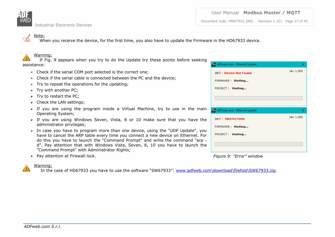
Note: When you receive the device, for the first time, you also have to update the Firmware in the HD67933 device.
Warning: If Fig. 9 appears when you try to do the Update try these points before seeking
assistance:
Check if the serial COM port selected is the correct one;
Check if the serial cable is connected between the PC and the device;
Try to repeat the operations for the updating;
Try with another PC;
Try to restart the PC;
Check the LAN settings;
If you are using the program inside a Virtual Machine, try to use in the main Operating System;
If you are using Windows Seven, Vista, 8 or 10 make sure that you have the administrator privileges;
In case you have to program more than one device, using the "UDP Update", you have to cancel the ARP table every time you connect a new device on Ethernet. For
do this you have to launch the "Command Prompt" and write the command "arp -d". Pay attention that with Windows Vista, Seven, 8, 10 you have to launch the "Command Prompt" with Administrator Rights;
Pay attention at Firewall lock.
Warning: In the case of HD67933 you have to use the software “SW67933”: www.adfweb.com\download\filefold\SW67933.zip.
Figure 9: “Error” window
Industrial Electronic Devices
ADFweb.com S.r.l.
User Manual Modbus Master / MQTT
Document code: MN67933_ENG Revision 1.101 Page 38 of 45
TEMPLATE STRING: DEFINITION OF MQTT PAYLOAD
In the section “Set Communication” of the SW67933, if “Synchronous” mode is selected, it is possible to define a Template string for the MQTT messages. The template is necessary in order to define the structure of the payload of the MQTT message and the info contained. It is possible to have a simple text format or a JSON format.
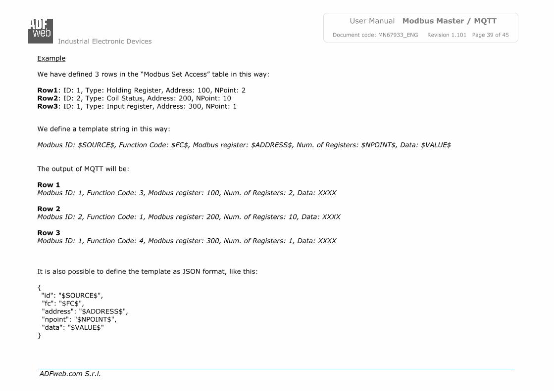
This template is valid for the Modbus requests in reading. The definition of the template can be done using Key words, used to link a specific information of the Modbus requests. The key words used and their meanings are:
SOURCE: ID of the Modbus slave
FC: Function code
ADDRESS: Modbus register
NPOINT: Number of consecutive Modbus registers
TYPE: The type of message is defined (request or response)
CRC: validation of the CRC (OK or wrong)
VALUE: value of the Modbus variable
DESC: description of the Modbus request (define in the “Modbus Set Access” table)
DATA: Modbus string (hex format)
TIME: date and time of the Modbus message
Warning: The key words must be defined between “$” chars in order to be recognized (Ex.: $DATA$).
Industrial Electronic Devices
ADFweb.com S.r.l.
User Manual Modbus Master / MQTT
Document code: MN67933_ENG Revision 1.101 Page 39 of 45
Example We have defined 3 rows in the “Modbus Set Access” table in this way:
Document code: MN67933_ENG Revision 1.101 Page 40 of 45
MODBUS WRITING WITH SYNCHRONOUS MODE
If “Synchronous” mode is selected, in order to send the Modbus writing requests it is necessary to use a specific MQTT payload. In this way, the converter can get all the info ned and compose the Modbus request. It is necessary to use a JSON format, described below: {
Document code: MN67933_ENG Revision 1.101 Page 43 of 45
ACCESSORIES:
Order Code: AC34011 - 35mm Rail DIN - Power Supply 220/240V AC 50/60Hz – 12 V DC
Order Code: AC34012 - 35mm Rail DIN - Power Supply 220/240V AC 50/60Hz – 24 V DC
Industrial Electronic Devices
ADFweb.com S.r.l.
User Manual Modbus Master / MQTT
Document code: MN67933_ENG Revision 1.101 Page 44 of 45
DISCLAIMER:
All technical content within this document can be modified without notice. The content of the document is a under continual renewal. For losses due to fire, earthquake, third party access or other accidents, or intentional or accidental abuse, misuse, or use under abnormal conditions repairs are charged to the user. ADFweb.com S.r.l. will not be liable for accidental loss of use or inability to use this product, such as loss of business income. ADFweb.com S.r.l. shall not be liable for consequences of improper use.
OTHER REGULATIONS AND STANDARDS:
WEEE INFORMATION
Disposal of old electrical and electronic equipment (as in the European Union and other European countries with separate collection systems).
This symbol on the product or on its packaging indicates that this product may not be treated as household rubbish. Instead, it should be taken to an applicable collection point for the recycling of electrical and electronic equipment. If the product is disposed correctly, you will help prevent potential negative environmental factors and impact of human health, which could otherwise be
caused by inappropriate disposal. The recycling of materials will help to conserve natural resources. For more information about recycling this product, please contact your local city office, your household waste disposal service or the shop where you purchased the product.
RESTRICTION OF HAZARDOUS SUBSTANCES DIRECTIVE
The device respects the 2002/95/EC Directive on the restriction of the use of certain hazardous substances in electrical and electronic equipment (commonly referred to as Restriction of Hazardous Substances Directive or RoHS).
CE MARKING
The product conforms with the essential requirements of the applicable EC directives.
Industrial Electronic Devices
ADFweb.com S.r.l.
User Manual Modbus Master / MQTT
Document code: MN67933_ENG Revision 1.101 Page 45 of 45
WARRANTIES AND TECHNICAL SUPPORT:
For fast and easy technical support for your ADFweb.com SRL products, consult our internet support at www.adfweb.com. Otherwise contact us at the address [email protected]
RETURN POLICY:
If while using your product you have any problem and you wish to exchange or repair it, please do the following:
Obtain a Product Return Number (PRN) from our internet support at www.adfweb.com. Together with the request, you need to
provide detailed information about the problem.
Send the product to the address provided with the PRN, having prepaid the shipping costs (shipment costs billed to us will not be accepted).
If the product is within the warranty of twelve months, it will be repaired or exchanged and returned within three weeks. If the product is no longer under warranty, you will receive a repair estimate.